a comparative study of risc vs cisc philosophies€¦ · instruction set computer (risc). in...
TRANSCRIPT


A Comparative Study of RISC vs CISC philosophiesof Implementing Mathematical Functions
by : Rupaka Mahalingaiah
Committee Chairperson : Dr. Morton Nadler
(ABSTRACT)
A comparative study of the RISC philosophy of implementing mathematical
functions vs the CISC philosophy of implementing the same functions is
undertaken. This study tries to verify wheter the RISC philosophy is suited
for the computers designed to run specicfic applications like the realtime
systems. A CISC processor is used as a platform machine and several
mathematical functions are implemented in both the philosophies. Test
programs are run on the platform machine to compare the results of the
implementation of the mathematical functions in both the philosophies.


Ill
TABLE OF CONTENTS I
Section 1
Introd«nc‘lä¥0n ................................ 11.1 Background ............................ 1
1.2 Goals ............................... 1
1.3 Means ............................... 2
1.4 Parameters of comparison .................... 3
1.5 Thesis organization........................ 3
Section 2
The Platform ................................ 4
2.1 About this chapter ........................ 4
2.2 The Architecture ......................... 4
2.3 The CPU ............................. 5
2.4 The RISC Concept ...................... 12
iv
l .-

TABLE OF CONTENTS [continued]
Section 2 The Platform [continued]
2.5 Analysis of the Micro5 for the RISC policy ........ 14
2.6 Special Microcode features in the Micro5 .......... 21
Section 3
The Comparison Means ......................... 23
3.1 The mathematical functions for comparisions ........ 23
3.2 Algorithms for the functions ................. 25
3.2.1 The Square Root Function............... 25
3.2.2 The Natural Logarithm Function ..........L 26
3.2.3 The Sine function.................... 293.3 Implementation of Functions ......;.......... 33
3.3.1 The SQRER Instruction ................ 35
3.3.2 The LOGER Function ................. 39
3.3.3 The SINER Function.................. 42
V

TABLE OF CONTENTS [continued]
Section 3 The Comparison Means [continued]
3.4 The Primitive Instructions................... 46
Section 4
Conclusions ............................... 5 1
4.1 The Test Programs ....................... 51
4.2 Results ............................. 56
4.3 Conclusions........................... 61
4.4 Further Research Work .................... 64
vi

I
TABLE OF CONTENTS [continued]
Section 5
...................................... 64
5.1 BIBLIOGRAPHY ....................... 65
5.2 Appendix A .......................... 67I
5.3 Appendix B........................... 68
5.4 Appendix C .......................... 69
5.5 Appendix D .......................... 86
5.6 VITA ..............................102
vii
I

LIST OF FIGURES
I2-1. 'I'he Micro5 Pipeline Stages ...................... 7
2-2. The Micro5 Timing ........................... 8
2-3. The Micro5 Block Diagram ..................... 10
2-4. The Execution Unit .......................... 12
2-5. The Stage3/4 Datapaths ........................ 19
2-6. The Register File 20
3-1. The Sine Function as Octants 31
3-2. The Single Precision Floating Point Format ............ 33
3-3. The Square Root Flow Chart .................... 38
3-4. The Natural Logarithmic Function Flow Chart 41
3-5. The Trignometric Sine Function Flow Chart ............ 45
viii

I
LIST OF TABLES
4-1. The Execution Results for the Square root Function ....... 57
4-2. The Execution Results for the Natural Logarithmic Function . . 58
4-3. The Execution Results for the Sine Function............ 60
ix

1. Introduction
1.1 BackgroundTraditionally, as the demand on the performance of the computer grew, more
and more hardware features were added to the computer hardware. This
resulted in added instructions to the instruction sets. At present, there are
some computer architectures that have transcendental functions in their
instruction sets. This evolution brought about some disadvantages with it. The
development time and the cost of such a processor increased considerably.
This led to a new type of architectural philosophy known as the Reduced
Instruction Set Computer (RISC). In contrast, the traditional architectures
came to be known as the Complex Instruction Set Computers (CISC).
1.2 GoalsThe aim of the research work undertaken here is to compare the CISC policy
of implementation of some mathematical functions vs. the RISC policy of
implementation of the same functions on a CISC machine. It has been argued
that for some real time applications, hard instructions implementing the
mathematical functions can outperform the RISC implementation of the samee
functions. This work intends to study both of these implementation strategies
on some mathematical functions and compare the two.
1

" P Y
1.3 MeansThe platform used to perform the analysis is the Concurrent Computer
Corporation’s 3200 series Micro5 Central Processing Unit (CPU). The
functions chosen to do the comparisons were single—precision floating—point
trigonometric sine function, single-precision floating—point square root and
single—precision floating—point natural logarithm. These functions were
microcoded in the Micro5 microcode language. The same functions were then
implemented in macrocode using simple assembly level instructions. Some
primitive functions were added to the existing instruction set as assembly
— level instructions. These primitive functions were microcoded in the Micro5
microcode language and used in the macrocode of the mathematical functions
as user-level instructions.
Several algorithms were considered for the study. The execution capabilities
of the Micro5 and the compatability of the results to the previous 3200
machines were the prime factors in deciding the algorithms for this study. The
COordinate Rotation Dlgital Computer (CORDIC) algorithms could have
been a good match, but as the Micro5 can perform multiplications as fast as
~ the additions, the subtractions and the shifts, these algorithms were not
necessary. The division operations in the Micro5 are comparatively slower,
hence the selected algorithms are optimised against the divisions.
2

II
1.4 Parameters of comparison
The parameters used to compare the two strategies are: speed of execution,
development time, memory usage.
1.5 Thesis organization
The remainder of the thesis presents the details of the implementation of the
goal. The next chapter will describe the platform machine and the salient
features of the RISC architecture. Chapter 3 will describe the mathematical
functions chosen and the algorithms used to implement them. This will be
followed by a chapter on the result analysis and conclusions.
Appendix A has the instruction map of the 3200 architecture and the
Appendix B has a brief description of the 3200 instruction formats. Appendix
C has the macrocode listing of the implementation of the functions and the
° Appendix D has the microcode listings for the same functions.
II 3

i
2. The Platform
2.1 About this chapter
The platform used to perform the analysis is the Concurrent Computer
Corporation’s 3200 series Micro5 CPU. This chapter gives a brief description
of the 3200 architecture followed by a description of the Micro5 CPU. The
next section talks about the RISC architectural features that are pertinent to
this research work. This is followed by an analysis of the platform CISC
machine for RISC policy.
2.2 The ArchitectureThe 3200 architecture is a CISC architecture which was originally developed
in the early 1970s. The architecture is specially tuned for realtime
applications as it supports a multiprocessing system with a very fast interrupt
response time. Initially, the instruction set was very similar to that of the
IBM 360 architecture’s instruction set. It has evolved over the years to
support some specific real time applications and, presently, has over two
hundred instructions?. The architecture supports eight basic types of
instruction formats? with the length of the instruction varying from two bytes
? see Appendix A for a complete instruction set map of 3200 architecture.
? see Appendix B for a brief description of instruction formats. For a detaileddescription refer to [1]
4

-. , é
Eto twelve bytes. The instructions in the memory are halfword aligned. I
The architecture supports logical, integer, character string, binary coded
decimal and floating—point formats, with the length of the data varying from
one to sixty four bits. The 3200 series of machines runs the OS32 operating
system for real—time applications. The operating system supports
multiprocessing. This multiprocessing capability gives the 3200 system large
grain parallelism.
2.3 The CPUThe Micro5 is a four—stage pipelined, single-board, 32-bit processor. It is a
horizontally microcoded machine. The microword is 96 bits long and controls
all four pipeline stages of the machine. The processor has 4k words of
instruction cache and another 4k words of data cache. It has 16
general—purpose registers, eight single-precision and eight double—precision
registers available to the user as the user register set. To increase the context
switching speed, the CPU actually has 4k words of registers out of which lk
is used as a microstack. There are eight multiples of the user register set.
Figure 2-1 shows the basic pipeline structure of the CPU. Stage 1 performs
the instruction fetching and the instruction alignment. It also has the
instruction cache. Stage 2 has the microsequencer, which controls the
{ 6

5
sequence of operations, and the address generation logic which generates the
addresses of the operands. The translation of the virtual address to the real
address takes place during this phase. Stages 3 and 4 consist of the register
files, the data cache and the execution unit. The execution unit performs the
actual execution of the instruction and sets up the status. The status is
partially used by the stage 2 in decision making. The CPU interfaces with the
system through a high—bandwidth system bus known as the SBUS?.
[ For more information on the SBUS refer to [2]
, 6

l„ _ l
STFIGE 1 STFIGE 2 STRGE 3 & L1
IIS CONTROLnasaucttna FETCH nrcacsznusacza ascxstza FILE!uastauctxau cacnz cmntact staat DHTR cacuzKNSTRUCTKGN auau LITEHRL azsxstca anuazss status Exzcuttuu urutuastauctxnu nznoat aonnsssv1ntuaL anna XLIT
S BUS INTEBFHCE
SBUS T PFITH SBUS F PHTH
Figure 2-1 The Micro5 Pipeline Stages
The basic clock cycle time of the Micro5 is 100 nanoseconds(ns). Figure 2-2
shows the basic How of the pipeline. Instructions are fetched and aligned in
the first 100ns. The operand address calculation takes place during the second
10011s. This stage also determines the sequence of flow of execution of the
instructions. The operands are fetched during the next 50ns. The actual
l 7

I
operation execution occurs during the following 100ns. This is followed by
another Süns of writing of the results.
THE MICHOS BHSIC PIPELINE TIMING
6 166 266 300 666
I ms Feten I 6666 cntc I ns66I sxscurs I HRITEI
Fig11re 2-2 The Micro5 Timing
Figure 2-3 depicts a high level block diagram of the MicroS processor. The
figure shows the pipeline stages of the processor along with the functional
blocks and their interconnections. The prefetch unit in stagel prefetches up to
8

II I
32 words of instructions ahead of the program counter. The instruction cache
is two—way interleaved and can be accessed simultaneously. The alignment
unit selects the current instruction from the output of the instruction cache.
The map—ram unit maps a user instruction to a control store address.
The microsequencer in stage2 generates the control store address for the
microcode execution. the control store is 96-bit wide and controls the
execution of most of the processor. The interrupter/cds unit controls the
interrupt handling and the interfaces to the control diagnostic system(cds)’t.
The register address unit generates the addresses for the register unit. The
address—calculation unit calculates the memory addresses for the data and the
instruction streams. lt uses the duplicate user register (dur) for indirect
address computation. The virtual address translation unit translates the virtual
address to the real address. This is implemented as a content addressableÄ
memory (CAM VAT) in the Micro5 processor.
i‘The cds is the bootup and monitor system for the 3200 system.
} 9I C

syggglI
STRGE2I
STRGES l STRGELI
·lkalßä
11-:!n!¤¤-F
Figure 2-3 The Micro5 Block Diagram
S·tage3 and ·stage4 consists of the registers, data cache and the execution unit.
The register files are implemented as two 4k word rams. The two sets are
identical at all times and effectively act as dualport rams. The data cache is
implemented as a two set associative 4k ram.
10

1
Figure 2-4 shows the block diagram of the execution unit. The equalization
gate array equalizes the floating point numbers and byte aligns the integer
numbers. The arithmetic/logic unit or the multiplier performs the actual
operation. The byte rotate realigns the integer results while the normalization
gate array normalizes and rounds the floating point results. The condition
code gate array generates the condition codes for all the operations. A 10-bit
field from the microword is used to generate 96-bit wide execution control
signals.
In the Micro5 CPU, most integer instructions execute in one cycle, while
most single—precision floating-point instructions take two cycles to execute.
On average, double—precision floating—point instructions take six cycles to
execute.
ill

1
\E
_. RBUS BBUS; U l
F
g ij CUNTHDLS) I DB aus{
-
an aus
HH29332 7LlHCT883S Cc_GHj_ ‘ ~ 3 Fl-U nuuirusÖ u¤¤¤6= ,5 _ S °°"“"°L§ sm_ · rn. ¤ fn HBUS
BTTE' ' HOTFITE
EU
HBUS
Figure 2-4 The Execution Unit
2.4 The RISC ConceptThe RISC architecture is becoming quite popular today and there are many
processors that are categorized as RISC processors. The definition of a RISC
processor is a little ambiguous. But generally, RISC processors have
hardwired control logic instead of the microcoded controls. They have smaller
12

1
instruction sets with simple instruction formats. They generally have fewer
pipelined stages than their CISC counterparts. The most common features of
the RISC processors are:
• Most operations are register—to—register only. LOAD and STORE are
the only instructions that access memory. This feature simplifies the
instruction set to a great degree.• The architectures support fewer operations and addressing modes. This
reduces the complexity in the control logic, enabling the
implementation of the control logic in hardware.• Most instructions are executed in one machine cycle time. Exceptions
to this rule are the floating—point instructions which may take multiple
cycles, necessitating a floating—point coprocessor in most present day
RISC machines.C • Instruction formats are simple and are full—word aligned. This reduces
the instruction decode logic complexity to a great extent. Also, the
virtual memory management overhead is greatly reduced as there can
be no page crossing across an instruction.• These machines use such techniques as ’delayed branching’ to avoid
pipeline penalties during branching. This implies that the next
instruction after a branch instruction will always be executed before
taking the branch.
13

I
• They use such techniques as the elimination of the data dependency
pipeline interlock by forwarding the result of one instruction to the
next if the result is the operand of the next instruction.• These architectures provide support of high—level language
programming by having some features to speed up frequent high—level
language statements, such as procedure calls, conditional branches etc.
Some of the machines use a technique called register windowing. This
technique speeds up subroutine calls. Here a procedure (or task) has a few
registers local to it and a few other registers that are global. Parameter
passing can be done through the global registers, while the local registers
reduce the register store—restore time overhead of procedure calls. Machines
that do not have this feature rely on their compilers to maximize register
usage.
2.5 Analysis of the Micro5 for the RISC policy
The Micro5 is basically a CISC machine with microcoded control unit. This
section describes the Micro5 processor as a RISC platform and defines the
constraints on the sample code used in this research to mimic the RISC
policy for implementing the mathematical functions.
I 14

[
The platform machine is not a load—store architecture machine. But, assuming
a hit in the data cache, most of the instructions are executed in one basicclock cycle time. Most of the instructions in 3200 architecture can have
register, memory or immediate operands. For the analysis of the two
philosophies in this research, only load and store instructions access the
memory. All other instructions operate on either register operands or
immediate operands. Even though an immediate operand is actually resident
in the memory, it is accessed through the instruction stream which can be
prefetched in the Micro5 processor. Hence, if the test program does not have
to page for the instruction stream'], using the immediate operands would not
result in any penalties.
The 3200 architecture has several addressing modes$. The processor is
designed in such a way that any addressing mode except the double—indexed
RX format and the RXRX§ format takes one cycle to decode. This is
achieved by having a copy of the current general user register set accessible to
iProgran1s shorter than the depth of the instruction cache (4k) can executewithout accessing the main memory after initial load. A page length is defined as 4kwords in the Micro5 processor and programs longer than the page length has toinvalidate the cache and re——access the main memoxy repeatedly.
¥Refer to [1] for the main instruction formats.
§RXRX format is used in commercial instructions only. Hence it is not a factorin this study. . 15

the address—calculation unit. This duplicate user register is accessed in the
stage2 of the pipeline whereas the actual register is located in the stage3‘l.
Coherency between the two is maintained by interlocking capability. If double
indexing mode addressing is used, the processor has to interlock for a cycle
to access the two registers for the address calculation. Hence the Micro5
processor can mimic the RISC processors addressing methodology, if double
indexing is not used in the test code.
The 3200 architecture instruction length varies from two to twelve bytes. The
Micro5 CPU has special hardware which can execute instructions of lengths
varying from one to three halfwords aligned on halfword boundaries without
any penalties. Referring to figure 2-3, the instruction cache is two-way
interleaved. But, during every access, both the odd—word and the even—word
instructions are fed into the alignment logic. The alignment logic selects the
required instruction for up to three halfwords from its input in one cycle.
3200 machines always generate instruction streams that are aligned on
halfword boundaries. Hence, there will be no decode pipeline interlock
penalty, if the instructions are from one to three halfwords in length.
Instructions longer than three halfwords will result in a pipeline interlock
penalty which is contrary to RISC philosophy. Hence the test code should
‘lRefer to figure 2-3.
16

a
use instructions of length varying from one to three halfwords to eliminate
any pipelinc penalties.
Single—precision floating—point (SPFP) instructions take two cycles to
execute. But the design of the machine is such that to execute a SPFP
instruction the operation is repeated twice. It does not use the sequencing of
two different operations to execute one SPFP instruction.
The delayed branching technique cannot be implemented in the macrocode.
Hence, there will be pipeline interlocking during the execution of conditional
branch instructions. The condition code in the Micro5 processor is set during
the stage4 and the branching decision is made in the stage2. Hence, one cycleA
interlock would be necessary on conditional branches. If, the code could
insert some instructions that would not update the condition codes before the
conditional branching, a pseudo—delayed branching could be implemented.
This would have required additional instruction formats and many more
additional instructions. This would conflict with the RISC policy of an
uniform instruction format with a few simple instructions. Hence, it was
decided not to try to implement this pseudo—delayed branching technique.
The Micro5 has a hardware feature that detects the dependencies between the
result of one instruction and the operand of the next instruction. In such a
17

case, a data forwarding technique called ’bypass' is used to forward the result
to the operand bus. Figure 2-5 shows the data flow in the stage3 and stage4
of the Micro5 processor. The input to the execution unit are the Abus and
the Bbus. Die ouput is the Wbus. The Abus can be sourced from either the
data cache or the register file. The Bbus is sourced from the register file.
Both the Abus and the Bbus can be sourced from the Wbus through the
bypass buffers ’bypass__a’ and ’bypass_b’. The register address generator in
the stage2 recognizes that the result of the previous instruction is the operand
for the current instruction and enables the bypass buffers to drive the Abus
and/or the Bbus. This enables the Micro5 processor to emulate the RISC
principle of reduction of data dependency interlocks.
18L

Sl!
STHGE3/ll DHTH PFITHS
Figure 2-5 The Stage3/4 Datapaths
Register windowing can be 1r1i1nicked on the platform machine by allocating
the lower half of the general registers and single—precision floating-point
registers as global registers and the remaining half as local registers. Figure
2-6 shows the register file structure in the Micro5 processor. There are eight
multiples of the user register set of 128-words each. During the execution of
19

I
a user task only one of these sets is visible to the macrocode. Multiple sets
are used by the processor during the context switch. The remaining 3k of the
register file consists of various system registers and a lk deep microstack.
THE HICRD5 REGISTER HRPaaa 32 BIT GENERRL REGISTERS
S2 BIT PROCESS STRTE REGS. ILSB = Il
32 BIT FLDRT REGISTER5S2 BIT SCRRTCH REGISTERS (LSB = ll
SU BIT INTEGER REGISTERS
64 BIT FLDRT REGISTERSDPF.H and DPF.L
SET 800888
SET 881188
...SET 111USD
8 SETS DF 128 32 BIT REGTRRNSIENT SCRRTCH REGS
BBB 16 SETS DF 16 L REG90*] 128 32 arr cru smra n ascgw 12a az an cru sims a ascRBB 2 SETS OF 128 SH BIT RIC REGC88
182Q DEEP HICRO—STRCK
Figure 2-6 The Register File
To emulate the register windowing technique, the first half of the user register
is used as shared registers for the parameter passing between the routines. The
20

last half is used in the macro test code as exclusive registers in a routine.
2.6 Specid Microcode features in the Micro5
The microcoded implementation of the function uses some features of the
.Micro5 which are not accessible to the user—level assembly language
instructions. This section lists some of these features that have major impact
in this study.
Even though the 3200 architecture does not support the delayed branching
technique, microcoded implementation can minimize the conditional branching
delays by using the two micro-condition-code registers. Also, micro
instructions can be easily inserted between the cycles of setting of a condition
code and using that condition code in decision making?. This would make
use of the wait cycle thus nullifying any penalty due to conditional branching.
The Micro5 processor has lk stack registers and 2k scratch registers?. These
are used extensively by the microcoded implementation ’for storing the
j*Refer to section 2.5
¥Refer to figure 2-6
21

!
constants and intermediate results: This reduces the memory access and the
system bus bandwidth requirement.
The ALU in the Micro5 is capable of performing operations on variable
width data from a 64-bit operand. This feature is used very effectively by
several mathematical computations in the microcoded implementation. For
instance, the microcode can perform a 64-bit shift in one cycle whereas it
takes about five cycles to implement the same in the macrocodet.
The microcode can also use a technique called multiway branching, which
enables the code to branch to any one of sixteen possible locations in a single
cycle. This significantly enhances the decision—making program—flow.
To have these features accessible to the user would mean an addition of many
more instructions and instruction formats. This would be against the basic
RISC philosophy. This research plans to evaluate the extent of performance
differences between the CISC implementation using these features and the
RISC implementation not using these features. I
‘l'Refer to the appendix C and the appendix D to see the actual coding of a64-bit left shift.
22

3. The Comparison Means
In this chapter, the mathematical function set of the 3200 architecture is
mentioned {oilowed by a brief description of the functions selected to perform
the comparison between the CISC policy of implementation and RISC policy
of implementation. The algorithms used to implement these functions are
described briefly followed by a description of the actual implementation in the
MicroS. The primitives used in the macro code implementation are listed with
brief descriptions of each of these functions.
3.1 The mathematical functions for comparisions
The 3200 architecture has many instructions to perform floating—point
mathematical functions. In addition to the basic operations of addition,P
subtraction, multiplication and division, the 3200 architecture has some
transcendental functions in its instruction set. The following is a list of the
sing1e—precision mathematical instructions supported by the MicroS:
• ATNER: SPFP Arctangent function ‘ ”
• COSER: SPFP Cosine function• EXPER: SPFP Exponential function• EXXER: SPFP to floating point Power function
23

6
• L10ER: SPFP Logarithm to Base 10 ·• LOGER: SPFP Natural Logarithm• SINER: SPFP Sine function• SNCER: SPFP Sine and Cosine functions• SQRER: SPFP Square root function
The above instructions are supported by the 3200 architecture as user—level
instructions. The Micro5 implements these functions in microcode.
For this study, SQRER, SINER and LOGER were the three functions
chosen to represent different kinds of functions. Square root is an algebraic
and quadratic function. Sine is a periodic trignometric function. Logarithm to
a natural base is an inverse exponential function. By using these three
functions as samples in this study, it is believed that conclusive data can be
obtained for a definitive analysis of the merits and the demerits of CISC
policy and RISC policy of implemention the mathematical functions.
These three functions are macrocoded as subroutines using the 3200
instruction set as well as some special primitive functions. The primitive
functions are microcoded in the Micro5 microassembly code and added to the
3200 instruction set as user—level instructions. Sample program loops are then
executed on the Micro5 using these subroutines. The same sample loops will
II 24

I
be executeä using the Micro5 microcoded instructions instead of the
subroutinezs. A comparative analysis will be undertaken based on the results.
3.2 Alwräms for the functions
Both the microcoded and the macrocoded functions should be based on the
same algonithnis to enable the comparison. This section briefly describes the
algorithms used by the three functions.
3.2.1 The Square Root Function
If 'x' is the input operand value and 'y’ the result, the square root is the root
of the algebraic equation:
3.2.1-1 y2 - x = 0 where 0 g x
then, y = i ·/x
note: 3200 systems generate positive y only
The Micro5 uses Newton’s iteration method to generate the square root
namely: ·
3.2.1-2 yn+1= yn — f(yn)/f’(yn)
where n is the iteration count
Here, f(y) = y2 — x
25
I .1

Substituting this in Newton’s iteration gives the Heron’s iteration for square
root:
3.2.1-3 yn+1= yn + .5 (x/yn — yn)
This iterative process converges for any positive x, and the number of
iterations required for the convergence depends upon the accuracy of the
initial approximation yo and the number of bits of accuracy desired.
In the Micro5, the initial approximation yo is calculated by a polynomial
evaluation method?. This method generates an initial approximation with
enough accuracy to require only one iteration of Newton’s approximation to
generate a single precision floating point square root.
3.2.2 The Natural Logarithm Function
The logarithmic function is defined as:
ln(x) = [ (1/x) . dx
The natural logarithm is the inverse function of the exponential function and
for any positive number x:
1n[exp(x)] = x = exp[ln(x)]
? The coefficients for the polynomial evaluation are obtained from [3].
26

The logarithmic function can be computed by a rapidly converging rational
approximation of the for1n:
3.2.2-1 ln(x) = 2 [ {[1/(2k+1)] =•= [(x-1)/(x+1)]2"*1} T
where, the summation E is for k varying from zero to infinity and
{[1/(2k+1)] # [(x-1)/(x+1)]2"*1} 2 0, for x ¢ 0
As a range reduction strategy, if B is the base of the computer floating point
arithmetic, then,
3.2.2-2 ln(x) = ln(B) »= 1ogB (x)
Using the above equation, the range of the function whose logarithm is to be
evaluated can be reduced to [1/B,1] by writing
3.2.2-3 x = f=•· B"where n is the floating-point exponent and f is the fractional part, lying
between 1/B and 1. Taking the logarithm of x to base B of equation 3.2.2-3
gives:
3.2.2-4 logB (x) = n + 1ogB (f)
By further range reduction, if f = (2‘J * g), where g lies between 1/2 and 1,
1ogB (x) = n - (j/4) + 1ogB (g) (for B=16)
1ogB (g) can be approximated similar to 3.2.2-1 as:
3-2-2-5 1<>sB(g) = Kg-1)/(s+1l] R{[(g-1)/(s+1)]2}
T for detailed explanation and derivation refer to [3]
27

The above equation is used in the Micro5 to compute the logarithmicfunction. The rational approximation is of the form:
3.2.2-6 logß (g) = z [P(z?)/Q(z? )]
where z = [(g-1)/(g+1)] and P and Q are the two polynomialst:
P(z2) = PO + Plz?+Q(z?)= Qll + Qlz?
+Forsingle precision f1oating—point evaluation of the logarithmic function, the
first two terms of the polynomials generate results with the desired accuracy.
t The coefficients required to evaluate these polynomials are taken from [3]
28

3.2.3 The Sine function
The trignometric sine function is a periodic function with a period of 2ll.
This function can be defined by the Taylor series for an operand x as:
3.2.3-1 sin(x) =[ {[(—1)k/ (2k+1)!] =•= x2"*1}
Some useful properties of sine functions are:
sin(-x) = —sinx
sin(x) = sin(x+2kH)
sin(x) = cos(ll/2-x)
This sine function can be calculated by using a polynomial approximation
with uniform convergence known as the Chebyshev series which is defined as:
3.2.3-2 sin(x) =
0.5COwhere,Tn (x) = cos(ncos‘1(x))
and the coefficient,
Cn = 2/ll _[ {sin(x)Tn(x) / 1/ (1—x2 dx‘1’
Substituting the Tn (x) polynomials into the Chebyshev series a polynomial
expansion can be obtained.
1* these coefficients are obtained from [3] in Micro5 implementation
29
an

ä
As a sine function is periodic over the range 2ll, any operand can be range
reduced to lie between 0 to 2lI. This range can be further subdivided into
eight octants of ll/4 width each as shown in figure 3-1.
There are two octants that are distinct out of the eight. The other octants are
either horizontal and/or vertical mirror images of one of the two distinctcurves. From the figure it can be seen that octant-0 and octant—2 are twodistinctive curves. Octant-1, for instance is the horizontal image of octant—2
and octant-4 is the vertical image of octa11t-0. W
V 30t r 1.-

I I
I I I I I ' Ijé I I I I II I I I I
I I I II I I I IOCTHNTG I OCTFINTI OCTFINTZI ÜCTHNT3 OCTRNTII OCTRNTS OCTHNT6 I OCTRNT7 X
I I I I I II I I I II I I I I I I II I I I I II I I I I II I I I • I
Figure 3-1 The Sine Functionias Octants
The octant—O, which lies between O and II/4, is the sine curve whereas the
octant-2 lying between II/2 to 3II/4, displays the properties of the cosine
curve. Hence two types of series are required to compute the sine fI1nction.
Depending upon which octant the operand falls into, it may either be required
to compute the sine series or the cosine series.
I31

1The following table lists the octants and their series. Here, (1-X) denotes a
horizontal imaging and ’—’ denotes the vertical imaging.
Octant Range Series
0ctant—0 0 to 11/4 SIN(X)
octant—1 11/4 to 11/2 COS(1— X)
0ctant—2 11/2 to 31]/4 COS(X)
octant-3 31]/4 to 11 SIN(1— X)
octant—4 11 to 511/4 —SIN(X)
octant-5 511/4 to 311/2 —COS(l— X)
octant—6 31]/2 to 711/4 —COS(X)
octant—7 711/4 to 211 -SIN(l—X)
The above sine and cosine series are calculated as polynomials of X2. The
simplified Chebyshev polynomial expansion for the sine series in the range 0
to 11/4 is:
3.2.3-3 SINE = SCX + Slxs + SCXS + SCX?
+andthat for the cosine series is:
3.2.3-4 COSINE = CC + CIXQ + CCX4 + CCX6
+Forsingle—precision floating—point numbers, the first four terms of either
series generate results precise enough for the 3200 architecture.
1[
32

3.3 Implementation of Functions
This section describes the instructions and their implementation strategy in the
Micro5. The instructions are of single—precision f1oating—point format, which
has a hexadecimal seven—bit exponent, twenty-four—bit signed mantissa and a
sig11 bit which is set when the mantissa is negative. The exponent is in excess
64 format.? Figure 3-2 shows the bit positioning of the single precision
floating point format data representation in 3200 architecture.
3 1 2 LL 0
ä E X P M Fl N T I S S Fl
Figure 3-2 The Single Precision Floating Point Format
i refer to [1] for a detailed description of this format
33

I EHere, bit 31 is the mantissa sign bit, bits 30 through 24 are the biased 64
exponent and bits 23 to 0 are the mantissa.
In the Micro5 implementation of the mathematical functions, the
single—precision floating—point number is split into mantissa and exponent
parts and the two are operated upon separately. This is done to increase the
accuracy of the final result by operating on a 32 bit mantissa instead of a 24
bit mantissa during the intermediate steps. The final result is generated by
combining the mantissa and the exponent parts of the result and r*rounding1'
the result to a 24 bit mantissa.
1* In a 32 bit SPFP format, we have 2 digits of exponent followed by 6digits (a digit = 4 bits) of mantissa. During the FP operation, the mantissa isextended to 8 digits (32 bits) and at the end of the operation, the result is truncatedback to 6 digits and the remaining 2 digits are used as guard digits to performrounding. The 3200 architecture defines that we perform a nonbiased roundingknown as the R*Rounding which is defined as:— if the most significant guard digit(MSGD) is hexadecimal 7 or less, no roundingis performed.— if the MSGD is hex 8, and all other guard digits are 0, then the LSB of the finalresult is forced to 1.— if the MSGD is hex 8, and any other guard digit is a nonzero; or if the MSGD isgreater than 8, final result is incremented by one. ·
34

3.3.1 The SQRER Instruction
The function SQRER generates the square root of a positive single—precisionfloating—point number. A negative operand results in a function range fault.The instruction is of the register—to—register format? and in 3200 assembly
language it appears as:
SQRER F2,F1where F2 and F1 are single precision floating point registers. F1 is thesource register containing the operand and F2 is the destination register forthe square root of the operand in F1.
The macrocoded and the microcoded implementations of this function can be
envisioned to tread through the following steps:
1. Test if the input operand is negative; if so exit as error.
2. Test if the input operand is zero; if so make the result zero and exit.3. Spilt the operand into mantissa and exponent parts. Operate on each
of them separately. _
4. Generate the normalizing factor for the result based on Whether the
mantissa is less than 1/4 and the exponent is odd/even.i
+ refer to [1] for various instruction formats of 3200 architecture.
Ä35

1
5. Convert the mantissa into a floating—point number and generate the
initial seed from the polynomial evaluation method.
6. Use this seed in Eq. 3.2.1-3 to generate the square root of the
mantissa. The exponent is divided by 2 to generate the exponent of
the square root. ” —
7. Combine the exponent and the mantissa of the result and multiply the
floating point result with the predetermined (step 4) normalizing
q factor to generate the required square root result.
About 40% of the total time of evaluating the function is spent in the initial
seed evaluation. Another 40% of the total time is spent in one iteration of
the approximation. The approximation generated here is accurate enough that
it requires only one iteration to generate a result with an accuracy of 32—bits.
It is possible to use a lookup—table to generate an initial seed. If a seed with
8—bits of accuracy was used, than two or three? iterations would be required
to generate the result. For the above algorithm$, this would be slower than
?Two iterations would give a 32-bit result, but because of the r*rounding, itwas seen that three iterations were required to generate a result compatable to other3200 machines.
¥Newton—Raphson’s algorithm without any divides in its approximation couldbe effectively used here. But, it would imply the use of some very specific hardwarefunctions which could not be used as the user—level instructions for RISCphilosophy implementation.
361- --

/
using an initial seed approximation.
The Appendix C has the macrocoded function listings and the Appendix D
has the microcoded function listings. Figure 3-3 shows the flow chart of the
implementation of the square root function.
{37

(
ENTRY
OPERRNO YESNEGRTXVE
Ä T
Y YES OPERRNOZERO
' T
' nssuu zsno srur
uv-samenNORHRLISINOFRCTOR
INITIRL SEEO
EVRLURTERPPROXIRRTION
COHBINEHRNTISSR-EXP
OENERRTEFINRL RESULT
EXIT
Figure 3-3 The Square Root Flow Chart
3.3.2 The LOGER Function
The function LOGER generates the natural logarithm (logarithm to base e) of
a positive single—precision f1oating—point operand. A negative operand results
in a function range fault. In 3200 assembly language this register—to—register
format instruction appears as:
LOGER F2,F1
where F1 and F2 are the source and the destination single precision floating
point registers respectively.
Steps for implementing this function are:
1. Test if the input operand is negative; if so exit as error.
2. Test if the input operand is zero; if so exit as error.
3. Split the operand into mantissa and exponent parts. Operate upon
them individually.
4. Generate the exponent to base two, bit normalize the mantissa and
adjust the exponent.
5. If the mantissa is less than the square root of 1/2, then compute z =
(g—.5)/(g+.5) where ’ g' is the mantissa.6. If the mantissa is greater than the square root of 1/2, then compute z
= (1-g)/(1+g), where ’g' is the mantissa.
NN 39

I
7. Compute the natural logarithmic function from the rational
approximation shown in Eq. 3.2.2-6.8. Generate the tloating-point result.
In the implementation of the above algorithm, 33% of the total time is spent
in step5/step6. 47% of the total time is spent in evaluating the rational
approximation (step7).
The Appendix C lists the actual listing of the macrocoded implementation of _
the natural logarithmic function and the Appendix D gives the microcode
listing of the same function. Figure 3-4 shows the flow chart of the
implementation of the natural logarithmic function.
40

I
ENTRY
OPERRNO YESNEGRTIVE
1
YES OPERRNOZERO
1
snnon srur
orznmauRNTISSRLESS THRN
ORT i/7
RS IN STEPS RS IN STEPS
EVRLURTEHPPROXIRRTION
CONSINEHRNTISSR·EXP
GENERRTEFINRL RESULT
EXIT
Figure 3-4 The Natural Logarithmic Function Flow Chart
41

3.3.3 The SINER Function
The function SINER generates the trignometric sine function of a
single—precision floating—point number. An input operand greater than 166
results? in a function range fault. The input value is in radians. In 3200
assembly language this register—to—register format instruction appears as:
SINER F2,F1
where F1 a11d F2 are the source and destination single precision floating point
registers respectively.
The sine function is implemented in microcode and macrocode using the
algorithm described in section 3.2.3. The steps followed are:
1. Test if the input operand is negative. If so, set a flag and complement
the operand to make it positive.
2. Check if the operand is greater than 166. If so, exit with a function
range fault.
3. Test if the operand is less than 16‘6. If so, set the sign of the
operand and exit with the operand as the result.
? Ranges are checked for hexadecimal base as the 3200 architecture’sf1oating—point format is to base 16.
42l i - -

4. Split the operand into mantissa and exponent.
5. Test if the operand is less than 16‘1. If so, perform a short range
reduction (multiply the operand by single precision [[/4). If the
operand is zero, set the octant to 0 and if the operand is not zero set
the octant to 4. Then, goto step 8.
6. If the operand is greater than 16'I, perform a long range reduction
(multiply the operand by double—precision [[/4).
7. Generate the octant of the operand. The three least significant bits of
the integer part of the operand constitute the octant.
8. Determine the type of series to be calculated based on the octant.
9. Evaluate the series based on Eqs. 3.2.3-3 or 3.2.3-4 to generate the
result.
10. Check the flag set in step 1 to see if the input operand was a negative
number. If so, complement the result and exit.
Long range reduction takes up 11% of the total execution time. Deterrnining
the octant takes 25% of the total time while determining whether the series is
sine or cosine takes up an additional 10%. The polynomial evaluation takes
about. 15% of the total execution time.
The Appendix C gives the macrocoded listing and the Appendix D gives the
microcoded listing of the actual implementation of the sine function. Figure
43

'44I ,

ENTRY
YES DPERRNDuammvc1 ~¤. XPUNEN 155am man ¤1
ND
ygg XPONENLESS THRN -
1
NU _
assuu-orsnauo srur
unsnnuuXPONEN YESLESS THRN -1
I
REDUCTION REBUCTION
GENERRTE SETOCTRNT DCTRNT
¤¤5IN[SINE SERIES CUSINE SERIES
BENERRTEFINRL RESULT
EXIT
Figure 3-5 The Trignometric Sine Function Flow Chart
45

3.4 The Primitive Instructions
For the macrocoded RISC type of implementation of the mathematicalfunctions, it is necessary to add a few basic instructions to the 3200instructions, to enable the assembly level code to have some of the benefits of
the Micro5 hardware. This section describes the philosophy behind theinstructions chosen followed by a list of the instructions used in this research.
One of the main factors that affects the performance of the Micro5 is the
memory data access time. So, it is essential that both the macrocoded
implementation and the microcoded implementation have proportional data
accesses from the memory. In the microcoded implementation, all of the
constants used by the algorithms are accessed from the microstack. Accessing
this microstack is not straightforwardi from the macrocode. Hence it was
decided to bring these constants from the instruction stream as immediate
data. As the instruction cache in Micro5 has an instruction prefetch featurei,
it is believed that this will reduce the data wait cycles.
trefer to [4]
trefer to [5]
46L

I
The 3200 architecture has immediate instructions for integer formats? only.
So single—precision floating—point immediate instructions were added to the
instruction set as primitive functions.
Originally, it was thought that instructions such as polynomial evaluation and
range reductions could be good candidates for primitive instructions. But,
upon coding, it was realized that these instructions did not have any
advantages over the simple floating·point immediate instructions as long as
the application program did not exceed the size of the instruction cache in the
Micro5. Hence, some of the more complex instructions were dropped.
The Micro5 execution unit has the capability of operating on different fields
of the operandsi. This feature can speed up the mantissa—exponent
separation, merging and bit—normalization processes considerably. Hence,
these functions were implemented as primitive instructions.
The Micro5 execution unit can perform the subtract or subtract—reverse
operations. The microcode makes use of this extensively. But the 3200
architecture does not have subtract reverse instructions. Hence,
?refer to [1]
?refer to [6]
47

subtract—reverse instructions were added as primitive functions in the
register—to—32-bit immediate data format.
As the 3200 architecture does not support an integer immediate multiply, that
instruction was also microcoded as a primitive function.
Following is a list of the primitive instructions used in this research work:
• SFPR G1,F1: split the exponent and the mantissa from the
single—precision f1oating—point register Fl. General register Gl gets
the exponent and G1+1 gets the mantissa. This is a
register—to—register format instruction.• CFPR Fl,Gl: align and merge the mantissa in general—purpose
4 register Gl and the exponent in general register Gl+1 into a
single—precision number in register Fl. This is a register—to—register
format instruction.• TNRZ G1,G2: bit—normalize the single—precision mantissa in general
register Gl and the bit exponent inlgeneral register G2. Both the
registers are modified and this is a register—to—register format
instruction.• MI G1, ’x’: integer multiply immediate instruction. Here, the value in
G1+1 is multiplied by the 32 bit immediate value ’x’ and the 64 bit
48L na

r 1
a result goes into Gl and G1+l. This is a register—to—32—bit immediate
data? format instruction.• DRS Gl, G2: short integer divide function. Divide the integer number
in register G1 by the integer number in register G2. This is a
register—to—register format instruction.• LEI F1, ’x’: load the single—precision floating—point register F1 with
the 32-bit immediate value ’x’. This is a register—to—32—bit immediate
data format instruction.• CEI F1, ’x’: compare the single precison floating point number in F1
with the 32-bit immediate value ’x’ and set the condition codes. This
is a register—to—32—bit immediate data format instruction.• AEI F1, 'x’: add the 32-bit immediate value ’x’ to the single
precision floating point number in F1. The result replaces the number
in Fl register. This is a register—to—32—bit immediate data format
instruction.• SEVI F1, ’x’: subtract the single precision number in F1 from the
32-bit immediate value ’x’( ie., subtract reverse). The result replaces
the number in Fl register. This is a register¥to—32—bit immediate data
format instruction.S
tappendix B gives a brief definition of this format and [1] has a more detaileddescription.
49

• MEI P1, 'x’: multiply the 32-bit immediate value ’x’ with the single
precision floating point number in F1. The result replaces the number
in F1 register. This is a register—to-32-bit immediate data format
instruction.• SVI Gl, ’x': subtract the integer value in G1 from the 32-bit
immediate value ’x’ ·(subtract reverse). The result replaces the number
in Gl register. This is a register—to—32—bit immediate data format
instruction. '
These instructions are added to the instruction set of the 3200 architecture.
The 3200 assembler — CAL/32 permits the user to define instruction
mnemonics within a program using the ’EQU’ statement?. Thus the above
primitives were microcoded in the Micro5 microcode language and used as
assembly level instructions in the macrocoded RISC type of implementation of
the mathematical functions. '
'frefer to [7]·
50

II
4. Conclusions
This chapter describes the test programs used to evaluate the two philosophies
of implementation of the transcendental functions and the results of running
these programs. This is followed by a section on analysis of the results. The
chapter ends with a section on suggested further research along the same line.
4.1 The Test Programs
Special programs where written to evaluate the functions. These programs are
required to run all of the three functions executing in both microcoded and
macrocoded implementation schemes. Three separate programs were written;
lt was decided to evaluate each of the functions on a set of data covering
various ranges for each function. Hence, in the begining of each each test
_ program a set of operand data was generated.i
This data is then loaded into the data cache by a loop in the test program.‘ This is done to eliminate the memory access time factor from the program
evaluation. Figure 4-1 shows a sample test program used to evaluate the
trigonometric sine function. The program is partitioned into sections and the
following explanation refers to these partitions. q
I51 .

Section one of the program generates the input operands for the test loop. At
first, the program generates exponent varying data for the entire range that the
function is valid. This is followed by a mantissa varying data for a small
range. Than the extreme cases are tested. Section two loads this data into the
data cache of the Micro5 processor. Section three initializes the data segment
and reads the real time clock. Section four executes the microcoded
functional implementation of the function. It also computes the time taken to
execute the function and this value will be stored in the general register G2
at the end of section four.
Section five reinitializes the data segment pointer and reads the real time 1
clock. Section six computes macrocoded implementation of the function and
stores the time spent in executing the function in general register G3.
Section seven stops the program and enables the examination of the registers.
Section eight has the subroutine to evaluate the macrocoded implementation
of the function.
52

x-------------------.---------..-...-.........................* SECTION ONE ‘r*
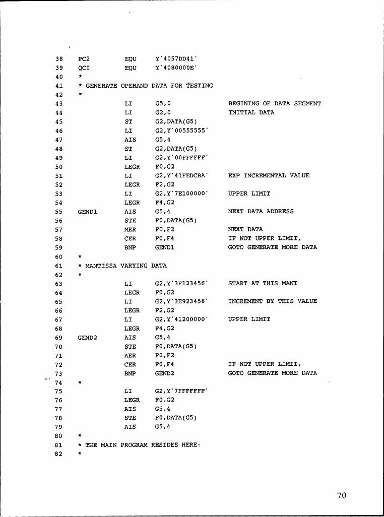
* GENERATE THE OPERAND DATA FOR TESTINGw
LI G5,0 BEGINING OF DATA SEGMENTLI G2,0 INITIAL DATAST G2,DATA(G5)AIS G5,4 NEXT ADDRESSST G2,DATA(5)LI G2,Y'OOFFFFFF° STARTING DATALEGR FO,G2LI G2,Y'4lFEDCBA” EXP INCREMENTAL VALUELEGR F2,G2LI G2,Y°47lOOO0O” UPPER LIMITLEGR F4,G2
GENDl AIS G5,4 NEXT DATA ADDRESSSTE F0,DATA(G5)MER FO,F2 NEXT DATACER FO,F4 IF NOT UPPER LIMITBNP GENDl GENERATE MORE DATA I
x
* MANTISSA VARYING DATAx
LI G2,Y'3FlOOOO0' START AT THIS VALUE. LEGR FO,G2
LI G2,Y°3E89F234' INCREMENTAL VALUELEGR F2,G2LI G2,Y'4l2000OO' UPPER LIMITLEGR F4,G2
GEND2 AIS G5,4STE FO,DATA(G5) WRITE DATAAER FO,F2 NEXT DATAM.CER FO,F4 IF LESS THAN UPPER LIMIT —
BNP GEND2 GENERATE MORE DATA*
LI G2,Y'46BFFFFF' ANOTHER DATA .LEGR FO,G2AIS G5,4STE FO,DATA(G5)AIS G5,4
*
53

- . |
*--———-—-—--—————————-—————————-———--------—-----.-...............
* SECTION TWO'k————----————-—-—--—————--———-——-——----———-------..............
1:
* LOAD THE DATA INTO DATA CACHE1:
LI G4,0GETDATA LE Fl4,DATA(G4) LOAD DATA INTO DCACHE
AI G4,4 NEXT ADDRESSCR G4,G5BNZ GETDATA
**—------—-—-—--—---——-----—---—-----------------.....-.........
* SECTION THREE~k——----—------—---—------———----—-——-------——-.................ic
* POINTER TO THE STARTING OF THE DATA SEGMENT1:
LIS G4,01:
* READ THE REAL TIME CLOCK·x
RRTC Gl,Gl1:
SECTION FOUR1-sv
* EXECUTE THE MICROCODED FUNCTIONsk
LOOPl LE Fl4,DATA(G4) GET DATABAL G0,SINE EXECUTE THE FUNCTIONSTE Fl4,0UT(G4)AIS G4,4CR G4,G5
“'BNZ LOOPl EXECUTE THE LOOP .RRTC G2,G2 READ THE REAL TIMECLOCKSR
G2,Gl TIME FOR LOOPl1:
54
L

*———--————-————-——————-———————-—————------—-—--—-—..-.........
* SECTION FIVE·k——————-—-------—-----—-——---—------—..-------—-......_........
*
* SETUP FOR MACROCODE LOOPING1:
LIS G4,0·x
* READ REAL TIME CLOCK*
RRTC G1,Gl
*·x.........-.
* SECTION SIX1:.......--...~k
* EXECUTE THE MACROCODE LOOP~x
LOOP2 LE Fl4,DATA(G4) GET THE OPERANDBAL G0,SINE EXECUTE THE FUNCTIONSTE Fl4,0UTl(G4)AIS G4,4 NEXT OPERANDCR G4,G5 DONE WITH LOOP?BNZ LOOP2 IF NOT, LOOPRRTC G3,G3 READ REAL TIME CLOCKSR G3,Gl TIME FOR LOOP2
SECTION SEVEN
STOP HERE*
BRK*1;................-„.---.--------------—-------------------------
* SECTION EIGHT hl _ —1;
SUBROUTINE TO EVALUATE THE FUNCTION ...1:
FIGURE 4-1
55

1
4.2 Results
This section gives the results of running the three test programs on the
Micro5 processor. To run the test programs, a special microcode set is used.
This microcode has the primitive functions as user level instructions in
addition to the 3200 instruction set. The test programs Were run under the
OS/32 operating system. The programs were run as user tasks from the Multi
Terminal Monitor (MTM)? mode.
As the programs were run with the operating system overhead, each program
was executed for six times to get a good sampling of the run time. In each
program, the function was evaluated in both the microcoded and macrocoded
implementations for about 4000 different data. At the time of executing these
programs, the CPU had no other user and there were no other user tasks
running.i
Table 4-1 gives the results of running the test program for the square root
function. Both the microcoded and the macrocoded implementations execute
at a similar speeds.U
? MTM is Concurrent Computer Corporation’s multi—user task monitor.
V 561 ..

1
TABLE 4-1 The Execution Results for the Square root Function
UCUDE MCODESHMPLE in 11106061:: IN HICHOSEC Hmm
1 16666 17967 E2 18523 17952 E3 18522 17951 .969L1 18521 17951 .9685 185116 17886 .9611
18565 16661 .676Nora: THE BRTI0 IS FOR MRCRUCODE/MICROCODE
The macrocoded implementation is a little faster than the microcoded
implementation. This can be attributed to some additional cycles in exception
case handling capabities that are present in the microcoded implementattion.l
Table 4-2 tabulates the results of running the test program for the natural
57L 1

logarithmic function. It can be seen that the microcoded implementation is
about 1.3 times faster than the macrocoded implementation of the same
function.
TABLE 4-2 The Execution Results for the Natural Logarithmic Function
UCODE MCODESRMPLE xu nxcnossc IN Mrcnnssc BHTIÜ
1 15711-1 21126 1.31111
2 15728 20956 1.332
3 1571-11 20907 1.328L1 1571111 20907 1.328
· 5 157111 20890 1.32919729 29999 1.329
NOTE: THE RRTIO IS FOR MFICROCOOE/MICROCOOE
The logarithmic function has many 64-bit operations. As mentioned earlier,
, 581- 1 _ _.

I
the microcode can handle these operations more effectively than the
macrocode.
Table 4-3 shows the results of running the test program for the sine function.
Here, the microcoded functional implementation is about 1.6 times faster than
the macrocoded funtional implementation.
" 59
I..

TABLE 4-3 The Execution Results for the Sine Function
SAMPLE UCODE MCODE RATIOIN NICROSEC IN MICROSEC
Il 9536 ·5339 IE2 9540 16366 E3 9543 16337 1.6074 9532 16366 1.612 °3 9641 16336 1.606
9542 16392 1.613NOTE= THE RATIO IS FOR NACROCODE/NICROCODE
In the implementation of the sine function, the microcode uses the multiway
branching technique? in some of its data-dependent decision—making.
? page 2-9 has a brief description of this technique, refer to [5] for a details.
60

4.3 Conclusions
From the results tabulated in the previous section, it can be concluded that
the microcoded implementation is of the same speed (as in square rootfunction) or faster than the macrocoded implementation of the same functionon the same CISC platform machine. In the microcoded implementation,every hardware feature is accessible and is made use of extensively. This is a
CISC philosophy of implementing the functions.
In the macrocoded implementation of the functions, the RISC philosophy isused. All the instructions used here are decoded in one cycle (with no
N pipeline delay penalty). The macrocoded implementation haspsuedo—register—windowing technique. This implies that during the subroutine
calls to evaluate the function, the user registers need not be stored and
restored. This technique not only saves time for the execution of additional
load—store instructions, but it also reduces data cache thrashing. Not all the
RISC machines have register—windowing. This implies that the result in the
previous section would be worse for the RISC implementation targetedltowards machines with no register—windowing. Hence, the CISC philosophy
of implementing the functions seems to be better than the RISC philosophy as
regards to the execution speed parameter.
i 61

The implementation time of the macrocode was considerably faster than the
microcode. This was especially true for the debugging phase of thedevelopment. Also, the macrocoded implementation can be run on any
processor running the same instruction set without much effort. But, as the
microcoded implementation uses features that are very specific to a processor,
it is not very easy to run the code even on other processors using the same
microassembler. It has to be re—coded for every processor. Thus the RISC
philosophy has an advantage over the CISC philosophy as regards to the
development time parameter.
The CISC implementation uses much less user memory than the RISC
implementation. With today’s huge memory systems, this may not be a very
significant. But, the bandwidth requirements on the system bus may be
higher in the RISC implementation (to counter this, most RISC architectures
have huge, hierarchical caching systems with write—back cache
implementations). Thus the CISC philosophy of implementation of the
functions is superior to that of the RISC philosophy as regards to the memory
usage.
If a RISC processor is designed to run at the same clock speed as the CISC
processor, the CISC processor would execute the mathematical functions
_ faster than the RISC processor. But, if the platform machine was designed to
62

•
run only the RISC—type of instructions, it would have had at least one less
stage of pipelining (which would speed—up branching). Also the cycle time
could have been shorter. Every pipeline stage has several exclusive features
which are necessary to execute the CISC instruction set. Without these
features it is possible to develop a platform machine with a faster clock cycle
using the same underlying technology.? If a RISC—type Micro5 processor was
to be developed and if the clock cycle of that processor was 62.5ns or less,
then all the mathematical functions would run faster in the RISC
implementation than it would in the CISC implementation.
Certain assumptions made in this study like the instruction and the data being
resident in the cache could be true in a uniprocessor implementation of a
system with large caches. In a multiprocessor environment it is harder to
assure the assumption that the instruction and data will reside in the cacheS
and hence the RISC philosophy of implementation could be much less
efficient than that seen in this study.
p It can be concluded from this study that the CISC philosophy of
implementing the mathematical functions is better thanwthat of the RISC
philosophy of implementing the same functions on the same platform machine.
? For instance in the Micro5 processor, if only uniform instructions were used,the stagel would not require the alignment unit.
l 63

h4.4 Further Research WorkBy coding several other functions using the technique outlined in this work, it
is possible to run some realtime application benchmarks, By running a few
interrupt driven benchmarks, a better conclusion can be drawn as to the
advantages and disadvantages of the two philosophies.
This experiment should be carried out on more than one platform machine to
compare the development time advantages.
The test programs should be run in a realtime mutitasking environment to
verify the bus traffic and memory usage parameters. By running several
realtime application benchmarks in multiprocessing environment with both
shared data and independent data segments, the memory access parameter canbe studied in detail.
i . 64ll „ .. _.

BIBLIOGRAPHY
1. "The Micro5 Instruction Set' Reference Manual", Concurrent
Computer Corporation, Tinton Falls, New Jersey.
2. Ken Yeager, "The SBUS Specification", Concurrent ComputerQ Corporation, Tinton Falls, New Jersey.
3. John F. Hart and others, "Computer Approximation", Robert E.
Krieger Publishing Company, Florida, reprint 1978.
4. Wendy Alexandar, "The Micro5 Microcode User Manual", Concurrent
Computer Corporation, Tinton Falls, New Jersey.
5. "The Micro5 Hardware Manual", Concurrent Computer Corporation,
Tinton Falls, New Jersey.
6. "The Micro5 Execution Unit", Concurrent Computer Corporation,
Tinton Falls, New Jersey.
7. "Com1non Assembly Language/32 (CAL/32) Reference Manual",
Concurrent Computer Corporation.
8. Daniel P. Siewiorek, Gordon C. Bell and Allen Newell, "Computer
Structures: Principles and Examples", McGraw—Hill, Inc., 1982.L
9. David A. Patterson, "Reduced Instruction Set Computers",
Communications of the ACM, January 1985, volume 28, number 1.
10. Robert P. Colwell, Charles Y. Hitchcock III, E. Douglas Jensen,
H.M.Brinkley Sprunt and Charles P. Kollar, "Computers,
L 65
L n

Complexity, and Controversy", IEEE Computer, September 1985
11. David Quong, Advanced Micro Devices, "Floating Point uP
Implements High-speed Math Functions", EDN, Reed Publishing
USA, Febraury 6,1986.
12. "Am29C300/29300 Data Book", Advanced Micro Devices, Sunnyvale,
California.
13. D. Patterson, "RISC Watch" Computer Architecture News, Volume
12, Number 1, March 1984.
66

Ü1

Ä Ä Ä 11
Appendix B
Thc 3200 Instruction formats:
REG1ST_ER·TD-REG1STER (RR) · -Ä I Ä H
° 0 ° 7 11 15OP R1
R2SHORTFORMAT (SF) ·O 7 11.15OP
R1 N N
. REG1STER AND INDEXEOSTDRAGE (RX1) 1 ' , _0 7 11. 15 . 18 31
”OP R1 X2 0 0 I A2 °
REG1STER AND 1NDEXED STORAGE 2 (RX2)O Ä 7 . 11 . 15. .17 . 31Ä. GP R1 X2 1 O2
REG1STER AND INDEXED STORAGE 3 (RX3) ·01 ‘· 7_ 11. · ·1S 17. . 20- _24 · 47
I OP R1 IFX2H' SÄX2 I A2 I
REG1STER AND 1MMED1ATE STORAGE 1 (R11)Ä Ä
0 7 11. 15 31
REG1STER AND IMMEDIATE STORAGE 2 (R12)0 '7 . 11 ° 15. ° 47§K ¤=» ¤ · Ä -1
REGISTER AND INDEXED STORAGE, REGISTER AND INOEXED STORAGE (RXRX1 ·0 7 _ 11.12 31/47 _39/E5 43/59 63/79/95
L1 I ADD1 OPMOD L2 ADD2 I
68

1 T
· 1
Appendix C
Macrocode source-code listing for the Square root functionc:
1 SQ.RT PROG2 TARGT 323 ORG X”100°4 SFPR EQU X'B0O8' SPLITS SPFP5 CFPR EQU X'B108' COMBINE SPFP
I 6 MEI EQU X'F201' MULTIPLY SPFP IMMEDIATE7 LEI EQU X'FCO1” LOAD SPFP IMMEDIATE8 CEI EQU X'FD01” COMPARE SPFP IMEDIATE9 AEI EQU X'FE01' ADD SPFP IMEDIATE
10 GO EQU 011 G1 EQU 112 G2 EQU 213 G3 EQU 314 G4 EQU 415 G5 EQU 516 G6 EQU 617 G7 EQU 718 G8 EQU 819 G9 EQU 920 G10 EQU 1021 G11 EQU 1122 G12 EQU 1223 G13 EQU 1324 G14 EQU 1425 G15 EQU 1526 FO EQU 027 F2 EQU 228 F4 EQU 4
i
29 F8 EQU 8 —30 F10 EQU 1031 F11 EQU 1132 F12 EQU 1233 F13 EQU 1334 F14 EQU 14
_ 35 Fl5 EQU 1536 PC0 EQU Y'4015F755”37 PC1 EQU Y'4111240C'
I69
1
1- -
55
38 PC2 EQU Y'4057DD41°39 QCO EQU Y'4080000E'40 * _41 * GENERATE OPERAND DATA FOR TESTING42 *43 LI G5,0 BEGINING OF DATA SEGMENT44 LI G2,0 INITIAL DATA45 ST G2,DATA(G5)46 LI G2,Y”00555555°47 AIS G5,448 ST G2,DATA(G5)49 LI G2,Y'00FFFFFF'50 LEGR F0,G251 LI G2,Y'4lFEDCBA” EXP INCREMENTAL VALUE52 LEGR F2,G253 LI G2,Y'7El00000' UPPER LIMIT54 LEGR F4,G255 GENDl AIS G5,4 NEXT DATA ADDRESS56 STE F0,DATA(G5)57 MER F0,F2 NEXT DATA58 CER FO,F4 IF NOT UPPER LIMIT,59 BNP GENDl GOTO GENERATE MORE DATA60 *61 * MANTISSA VARYING DATA62 *63 LI G2,Y'3F123456” START AT THIS MANT64 LEGR F0,G265 LI G2,Y”3E923456” INCREMENT BY THIS VALUE66 LEGR F2,G267 LI G2,Y°41200000' UPPER LIMIT68 LEGR F4,G269 GEND2 AIS G5,470 STE F0,DATA(G5)71 AER F0,F272 CER FO,F4 IF NOT UPPER LIMIT,73 BNP GEND2 GOTO GENERATE MORE DATA
75 LI G2 ,Y' 7FFFFFFF'76 LEGR FO,G277 AIS G5,478 STE F0,DATA(G5)79 AIS G5,480 *81 * THE MAIN PROGRAM RESIDES HERE:82 *
70

LI1
83 LIS G4,0 h84 GETDATA LE F14,DATA(G4) l
85 AI G4,486 CR G4,G587 BNZ GETDATA88 *89 * POINTER TO THE STARTING OF THE DATA SEGMENT90 *91 LIS G4,092 *93 * READ REAL TIME CLOCK94 *95 RRTC G1,G196 *97 * EXECUTE THE MICROCODED FUNCTION
' 98 *99 LOOP1 LE F14,DATA(G4) GET DATA
100 SQRER F14,F14 EXECUTE THE FUNCTION101 * STE F14,0UT(G4) WRITE FOR TESTING102 AIS G4,4 NEXT DATA103 CR G4,G5 DONE WITH LOOP?104 BNZ LOOPl IF NOT, GOTO LOOP1105 RRTC G2,G2 . IF DONE, READ THE TIME106 SR G2,G1 G2 HAS THE TIME107 *108 * SET UP FOR MACROCODE LOOPING109 *110 LIS G4,0111 * -112 * READ REAL TIME CLOCK113 *114RRTC115
*116 * THE LOOP FOR TESTING THE MACROCODE117 *118 LOOP2 LE F14,DATA(G4) GET THE OPERAND119 BAL G0,SQRT an .120 * STE F14,0UT1(G4)121 AIS G4,4 NEXT OPERAND122 CR G4,G5 DONE WITH LOOP123 BNZ LOOP2 IF NOT, GOTO LOOP2124 _ RRTC G3,G3 READ REAL TIME CLOCK125 SR G3,G1 G3 HAS TIME FOR LOOP2126 BRK127 *
71
L.,
I
I
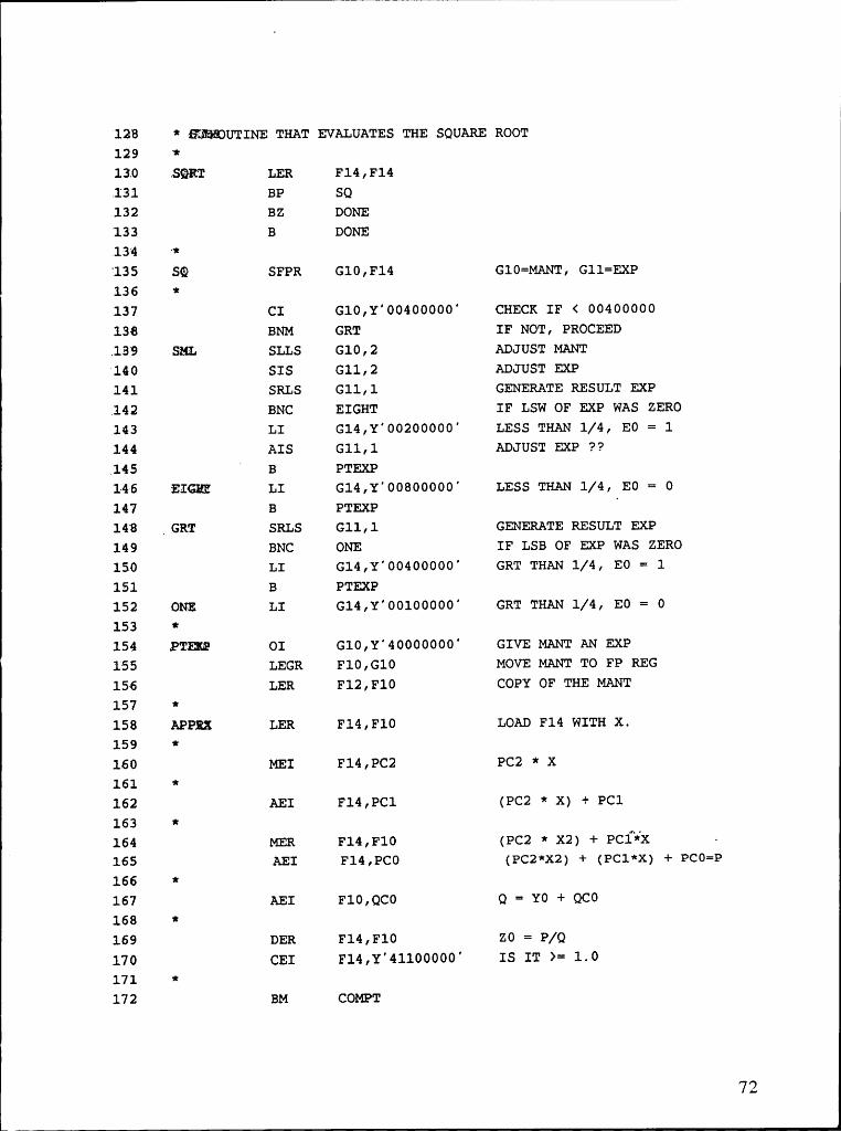
°128 * EEWEUTINE THAT EVALUATES THE SQUARE ROOT129 *130 .3QRT LER F14,F14.131 BP SQ132 BZ DONE133 B DONE,134 ·*135 SQ SFPR G10,F14 G10=MANT, G11=EXP136 *137 CI G10,Y'004000OO' CHECK IF < 00400000138 BNM GRT IF NOT, PROCEED.139 SML SLLS G10,2 ADJUST MANT‘l40 SIS Gll,2 ADJUST EXP141 SRLS G11,1 GENERATE RESULT EXP
,142 BNC EIGHT IF LSW OF EXP WAS ZERO143 LI G14,Y'00200000' LESS THAN 1/4, EO = 1144 AIS G11,1 ADJUST EXP ??.145 O B PTEXP°146 EIGHE LI G14,Y'OO800000' LESS THAN 1/4, EO = 0147 B PTEXP
I
148 _GRT SRLS G11,1 GENERATE RESULT EXP149 BNC ONE IF LSB OF EXP WAS ZERO150 LI G14,Y'O0400000' GRT THAN 1/4, EO = 1151 B PTEXP152 ONE LI G14,Y'00100000' GRT THAN 1/4, E0 = 0153 *154 PTEXP OI Gl0,Y'4000O00O' GIVE MANT AN EXP155 LEGR Fl0,G1O MOVE MANT TO FP REG156 LER F12,F10 COPY OF THE MANT157 *158 APPRX LER F14,F10 LOAD F14 WITH X.159 *160 MEI F14,PC2 PC2 * X161 *162 AEI F14,PC1 (PC2 * X) + PC1163 *164 MER F14,F1O (PC2 * X2) + PC1¥X —
O 165 AEI F14,PC0 (PC2*X2) + (PCl*X) + PCO=P
166 *167 AEI F10,QC0 Q = Y0 + QCO168 *169 DER F14,F1O ZO = P/Q170 CEI Fl4,Y°41100000' IS IT >= 1.0171 *172 BM COMPT
72
I
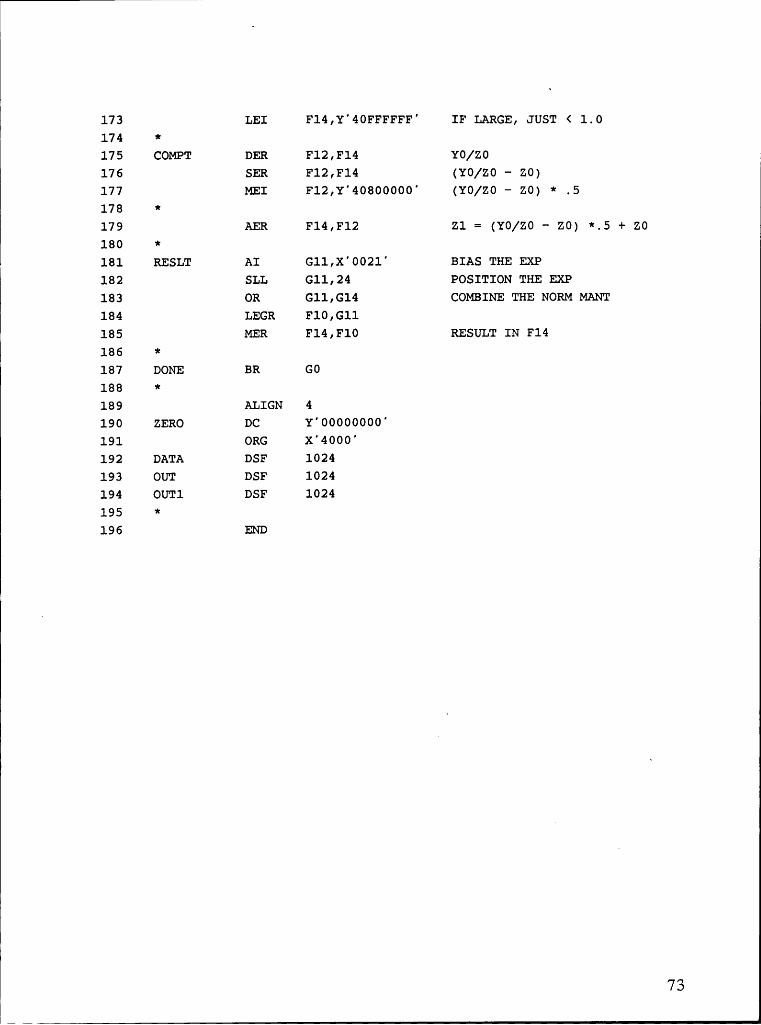
173 LEI Fl4,Y'4OFFFFFF' IF LARGE, JUST < 1.0174 *175 COMPT DER F12,F14 YO/ZO176 SER F12,F14 (YO/ZO — ZO)177 MEI F12,Y'4080000O' (YO/Z0 — ZO) * .5178 *179 AER F14,F12 Z1 = (YO/Z0 — ZO) *.5 + ZO180 *181 RESLT AI G11,X'OO21° BIAS THE EXP182 SLL G11,24 POSITION THE EXP183 OR G11,G14 COMBINE THE NORM MANT184 LEGR F10,G11185 MER F14,F10 RESULT IN F14186 *187 DONE BR GO188 *189 ALIGN 4190 ZERO DC Y°OO000OO0'191 ORG X'4000'192 DATA DSF 1024193 OUT DSF 1024194 OUTl DSF 1024195 *196 END
73

I
Macrocode source—code listing for the Natural logarithm function:
1 LOG.E PROG LOGE2 TARGT 323 ORG X'100'4 SFPR EQU X'B008' SPLITS SPFP5 CFPR EQU X'B108' COMPINE SPFP6 TNRZ EQU X'B408' BIT NORM MANT—G1,EXP—G28 SEVI EQU X'F001' SPFP SUBTRACT REV IMMD.9 MI EQU X°F101' MULTIPLY INTEGER IMMEDIATE
10 MEI EQU X'F201' MULTIPLY SPFP IMMEDIATE11 LEI EQU X'FC01' LOAD SPFP IMMEDIATE12 CEI EQU X'FD01' COMPARE SPFP IMMEDIATE13 AEI EQU X'FE0l' ADD SPFP IMEDIATE14 SVI EQU X'FF01' SUBTRACT REVERSE IMMEDIATE15 GO EQU 016 G1 EQU 117 G2 EQU 218 G3 EQU 319 G4 EQU 420 G5 EQU 521 G6 EQU 622 G7 EQU 723 G8 EQU 824 G9 EQU 925 G10 EQU 1026 G11 EQU 1127 G12 EQU 1228 G13 EQU 13
I
29 G14 EQU 1430 G15 EQU 1531 F0 EQU· 032 F2 EQU 2
_ 33 F4 EQU 4{E4 F6 EQU 6 —35 F8 EQU 836 F10 EQU 1037 F11 EQU 1138 F12 EQU 1239 F13 EQU 1340 F14 EQU 1441 F15 EQU 1542 O EQU Y'00000O00'
i74

—» I
43 ALOG2 EQU Y'40B17218°44 HALF EQU Y'00800000°45 SQRT5 EQU Y'00B504F4'46 PC0 EQU Y'F2BEEB21'47 PCl EQU Y'O3950899'48 OC0 EQU Y”95F75980'49 *50 * GENERATE OPERAND DATA FOR TESTING51 *52 LI G5,0 BEGINING OF DATA SEGMNT53 LI G2,Y°O0lO0000' INITIAL DATA54 ST G2,DATA(G5)55 LI G2,Y'O0555555'
I56 AIS G5,457 ST G2,DATA(G5)58 LI G2,Y'O0FFFFFF'59 LEGR FO,G260 LI G2,Y'41FEDCBA° EXP INCREMENTAL VALUE61 LEGR F2,G262 LI G2,Y'7ElO0000' UPPER LIMIT63 LEGR F4,G264 GEND1 AIS G5,4 NEXT DATA ADDRESS65 STE F0,DATA(G5)66 MER FO,F2 NEXT DATA67 CER FO,F4 IF NOT UPPER LIMIT,68 BNP GEND1 GOTO GENERATE MORE DATA69 *70 * MANTISSA VARYING VALUES71 *72 LI G2,Y'3F123456' START AT THIS MANTISSA73 LEGR FO,G274 LI G2,Y'3E923456' INCREMENT BY THIS VALUE75 LEGR F2,G276 LI G2,Y'4120000O' UPPER LIMIT77 LEGR F4,G278 GEND2 AIS G5,479 STE FO,DATA(G5)
hl ‘ -80 AER FO,F2 NEXT DATA81 CER FO,F4 IF NOT UPPER LIMIT,82 BNP GEND2 GENERATE MORE DATA83 *84 LI G2,Y°7FFFFFFF' MAX POSITIVE NUMBER85 AIS G5,486 ST G2,DATA(G5)87 AIS G5,4
75

88 *89 *‘THE TEST LOOP90 *91 LIS G4,092 GETDATA LE F14,DATA(G4)93 AI G4,494 CR G4,G595 BNZ GETDATA96 *97 * PQINTER TO THE STARTING OF THE DATA SEGMENT98 *99 LIS G4,0
100 *101 * READ REAL TIME CLOCK102 *103 RRTC G1,Gl104 *105 * EXECUTED THE MICROCODED FUNCTION106 *107 LOOP1 LE F14,DATA(G4) GET DATA108 LOGER F14,F14 EXECUTE THE FUNCTION109 STE F14,0UT(G4)110 AIS G4,4 NEXT DATA ·111 CR G4,G5 DONE WITH THE LOOP?112 BNZ LOOP1113 RRTC G2,G2 IF DONE, READ THE TIME
114 SR G2,Gl TIME TAKEN BY THE LOOP115 *116 * SET UP FOR MARCOCODE LOOPING ·117 *118 LIS G4,0119 *120 * READ REAL TIME CLOCK121 *122 RRTC G1,G1123 *124 * THE LOOP FOR MACROCODE TESTING
Ü.·
125 *126 LOOP2 LE F14,DATA(G4) GET THE OPERAND127 BAL G0,LOGE EXECUTE MACRO FUNCTION128 STE Fl4,0UTl(G4)129 AIS G4,4 NEXT OPERAND130 CR G4,G5 DONE WITH THE LOOP?131 BNZ LOOP2 IF NOT, GOTO LOOP2132 RRTC G3,G3 READ REAL TIM CLOCK
76L1

I
133 SR G3,G1 G3 HAS THE TIME FOR LOOP2134 *135 * STOP THE PROGRAM HERE TO EXAMINE THE REGISTERS136 *137 BRK138 *139 * SUBROUTINE TO EVALUATE THE LOGE FUNCTION140 *141 LOGE LER F14,F14142 BP LGE143 BZ EXIT144 B EXIT145 *146 LGE SFPR G13,F14 G13=MANT, G14=EXP147 *148 SI G14,X'0040' EXP—40H149 SLLS G14,2 EXP * 4150 TNRZ G13,G14 BIT NORM MANT 8 ADJUST EXP151 *152 GRT2 LI G11,0153 CLI G13,SQRT5 MANT < SQRT(.5)154 BNC CASEB155 CASEA SIS G14,1 EXP = EXP-1156 LI G12,Y'00080000° ”FLOOR”157 LR G10,G13158 SI G10,HALF (G - K)159 BZ UZERO IF H=0, U=0160 AI G13,HALF (G + K)161 LI G15,Y'400000O0' SIGN AND EXP OF U162 B FRAC163 CASEB LI G10,Y'01000000'164 SR G10,G13165 LI G12,Y'001000O0' 'FLOOR° _166 LI G15,Y'C0000O00' SIGN AND EXP OF U167 AI G13,Y'01000000' (1. + G)168 FRAC LIS G9,0 SHFCNT INIT
Ü.169 LR G14,G14 TEST EXP -170 BNZ COVF NO SCALING FOR NONZERO EXP171 SCALE CLR G10,G12172 BNC COVF173 SLA G10,4 IF LESS, IHA * 16174 SI G15,Y'01000000° EXP = EXP -1175 AIS G9,4 SHFCNT = SHFCNT+4176 B SCALE177 COVF CLI G10,Y'00F00000° OVERFLOW POSSIBLE?
77

1
178 BC NOOVF179 SLA G13,4 SHIFT DENOMRNATOR180 AI G15,Y'01000000' EXP = EXP + 1181 SIS G9,4 SHFCNT = SHFCNT — 4182 NOOVF DR G10,G13 H = (IHA/IHB)183 *184 LR Gl3,G11185 APPRX MR G10,G13 [G11,G10] = H*H186 SRA G10,0(G9) RESCALE187 SRA G10,0(G9) TWICE FOR H*H188 LR G9,G10 COPY H*H189 MI G8,PC1 PC1*(H2)190 *191 AI G8,PC0 PC1*(H2) + PC0192 SRA G10,2 IRK/4193 AI G10,QC0 IRK/4 + QC0194 LR G9,G8 .195 MR G8,Gl3 IH * IRN IN [G8,G9]196 DR G8,G10 IU IN G9197 *198 CLI G9,Y'01000000' IS IU < 1.199 BNC CONT200 SI G15,Y'01000000' LOWER THE EXP201 SLA G9,4 IU = IU *16202 CONT AI G9,8 ROUNDUP LAST DIGIT203 SRA G9,4 SHIFT DOWN204 OR G9,G15 PUT EXP205 RESULT FLR F14,G14
— 206 MRI’ F14,ALOG2 N*ALOG2207 *208 LEGR F12,G9209 AER F14,F12 N*ALOG2 + U210 EXIT BR G0211 UZERO LI G9,0212 B RESULT '
213 *214 8 DATA SEGMENT ·215 *216 ALIGN 4217 TEMP DSF 1218 ORG X'4000'219 DATA DSF 1024220 OUT DSF 1024221 OUT1 DSF 1024222 END
78

1
Macrocode source—code listing for the Sine function:
1 SINER PROG SINER2 TARGT 323 ORG X'100'4 SFPR EQU X°BO08° SPLITS SPFP5 CFPR EQU X'B108' COMBINE SPFP6 TNRZ EQU X'B408' BIT NORM MANT—G1,EXP—G27 DRS EQU X”B508' INTEGER DIVIDE SHORT8 SEVI EQU X'F0O1° SPFP SUBTRACT REV IMD.9 MI EQU X'F101' MULTIPLY INTEGER IMMEDIATE
10 MEI EQU X'F201' MULTIPLY SPFP IMMEDIATE11 LEI EQU X'FC01° LOAD SPFP IMMEDIATE12 CEI EQU X'FD01' COMPARE SPFP IMMEDIATE13 AEI EQU X'FE01' ADD SPFP IMMEDIATE14 SVI EQU X'FFO1' SUBTRACT REVERSE IMMEDIATE15 GO EQU 0
U 16 G1 EQU 117 G2 EQU 218 G3 EQU 319 G4 EQU 420 G5 EQU 521 G6 EQU 622 G7 EQU 723 G8 EQU 824 G9 EQU 9 _25 G10 EQU 1026 G11 EQU 1127 G12 EQU 1228 G13 EQU 1329 G14 EQU 1430 G15 EQU 1531 FO EQU 0 _32 F2 EQU 233 F4 EQU 4
hl~
34 F6 EQU 635 F8 EQU 836 F10 F EQU 1037 F11 EQU ll38 F12 EQU 1239 F13 EQU 1340 F14 EQU 1441 F15 EQU 15
79

_ n
42 O EQU Y'00O0O000'43 SC EQU Y'41145F30°44 SC1 EQU Y°5l7CClB7‘45 SC2 EQU Y”27220B00°46 C0 EQU Y'40FFFFFF'47 C2 EQU Y°C04EF4E3'48 C4 EQU Y”3F40EB99'49 C6 EQU Y°BEl4E35E'50 Sl EQU Y'40C90FDB'51 S3 EQU Y”C0l4ABBC” -52 S5 EQU Y'3EA32F49'53 S7 EQU Y”BD25AD0l'54 C1 EQU Y'40100000'55 *” 56 * GENERATE THE OPERAND DATA FOR TESTING57 *58 LI G5,0 BEGINING OF THE DATA SEGMENT59 LI G2,0 INITIAL DATA60 ST G2,DATA(G5)61 AIS G5,4 NEXT ADDRESS62 ST G2,DATA(5)63 LI G2,Y'0OFFFFFF' STARTING DATA64 ‘ LEGR F0,G265 LI G2,Y'41FEDCBA' EXP INCREMENTAL VALUE66 LEGR F2,G267 LI G2,Y'47l0000O' UPPER LIMIT68 LEGR F4,G269 GENDl AIS G5,4 NEXT DATA ADDRESS70 STE F0,DATA(G5)71 MER F0,F2 NEXT DATA72 CER FO,F4 IF NOT UPPER LIMIT73 BNP GEND1 GENERATE MORE DATA74 *75 * MANTISSA VARYING DATA76 *77 LI G2,Y'3F10000O' START AT THIS VALUE78 LEGR F0,G2 '" .
79 LI G2,Y'3E89F234' INCREMENTAL VALUE80 LEGR F2,G281 LI G2,Y'41200000” UPPER LIMIT82 LEGR F4,G283 GEND2 AIS G5,484 STE F0,DATA(G5) WRITE DATA
85 AER F0,F2 NEXT DATA86 CER FO,F4 IF LESS THAN UPPER LIMIT
Ä80

I -- ~ I
I
I87 BNP GEND2 GENERATE MORE DATA88 *89 LI G2,Y'46BFFFFF' ANOTHER DATA90 LEGR F0,G291 AIS G5,492 STE F0,DATA(G5)93 AIS G5,494 *95 * THE MAIN PROGRAM RESIDES HERE:96 *97 LI G4,098 GETDATA LE F14,DATA(G4) LOAD DATA INTO DCACHE99 AI G4,4 NEXT ADDRESS
100 CR G4,G5101 BNZ GETDATA102 *103 * POINTER TO THE STARTING OF THE DATA SEGMENT104 *105 LIS G4,0106 *
‘107 * READ THE REAL TIME CLOCK108 *109 RRTC G1,G1110 *111 * EXECUTE THE MICROCODED FUNCTION112 *113 LOOP1 LE Fl4,DATA(G4) GET DATA114 SINER F14,F14 EXECUTE THE FUNCTION115 STE F14,0UT(G4) ·116 AIS G4,4117 CR G4,G5118 ' BNZ LOOP1I EXECUTE THE LOOP119 RRTC G2,G2 READ THE REAL TIME CLOCK120 SR G2,G1 TIME FOR LOOP1121 *122 * SETUP FOR MACROCODE LOOPINGh,123 * —124 LIS G4,0125 *126 * READ REAL TIME CLOCK127 *128 RRTC G1,G1129 *130 * EXECUTE THE MACROCODE LOOP131 *
,81

II
I132 LOOP2 LE F14,DATA(G4) GET THE OPERAND133 BAL G0,SINE EXECUTE THE FUNCTION134 STE F14,0UT1(G4)135 AIS G4,4 NEXT OPERAND136 CR G4,G5 DONE WITH LOOP?137 BNZ LOOP2 IF NOT, LOOP
I
138 RRTC G3,G3 READ REAL TIME CLOCK139 SR G3,Gl TIME FOR LOOP2140 *141 * STOP HERE142 *143 BRK
I 144 *I 145 * SUBROUTINE TO EVALUATE THE SINE FUNCTION
146 *147 SINE LI G7,X'0'148 LER F14,F14149 BNM PLUS IF NEGATIVE,CHANGE SIGN150 LI G7,X'1'151 SEVI Fl4,X'0' MAKE POSITIVE152 *153 PLUS CEI F14,Y'471000O0' OUT OF RANGE?154 *155 BNM EXIT EXIT,IF OUT OF RANGE156 CEI F14,Y'3El00000' SMALL NUMBER?157 *158 BP SN IF NOT GOTO SINE ROUTINE159 LR G7,G7 CHECK SIGN160 BZ EXIT IF SMALL AND POSITIVE EXIT161 SEVI F14,X'O' IF NEGATIVE, CHANGE SIGN162 *163 LER F14,F14 SET CC164 B EXIT165 *166 SN SFPR G13,Fl4 G13=MANT, G14=EXP167 *168
M.CEI F14,Cl' IS IT < .1? .
169 *170 BNP SHORT IFSO,GOTO SHORT ROUTINE171 LR G11,G13 IF NOT, A 64 BIT MULT
172 MI G10,SC1 RANGE REDUCTION; MSW
I 173 *174 MI G12,SC2 RANGE REDUCTION;LS175 *176 AR G11,G12
I
82

11I
177 BNC SLL64 CARRY INTO THE LSB?178 AIS G10,1 IF YES,INCREMNT IT179 *180 SLL64 SLLS G10,6 64 BIT SHIFT FOR THE181 LR Gl3,G11 64 BIT MULTIPLY182 SLLS Gll,6183 SRL G13,26184 OR G10,G13 G10,G11 LEFT SHIFTED185 AIS G14,1 RANGE REDUCED MANTISSA186 *187 GETOCT LI Gl3,X'48' FIND THE OCTANT:188 SR G13,G14 SUB REVERSE?189 LR Gl2,Gl4190 SI G12,X'40' Gl2= EXP—40191 SLLS G13,2 Gl3= 4*(48—EXP)192 LR G9,G10193 SRL G9,0(G13) G9 = OCTANT194 NI G9,7 PKEEP LAST 3 LSB ONLY195 LI G8,X'20' BY G13196 SR G8,G13 G8,Gl5 = WORKREG
. 197 SLL G10,0(G8) SHIFT G10,G11198 LR G15,G11199 SRL G15,0(G13)200 OR G10,G15201 SLL G11,0(G8)202 LER F14,F14 OP = G10,G1l203 BP POS204 AIS G9,4 IF NEGATIVE OP,ALT OCT
‘ 205 *206 POS TI G9,1 ODD OCTANT?207 BZ NFLAG IF EVEN GOTO NFLAG
U208 SVI G11,0 IF ODD,NEGATE THE OP209 *210 BNC CONT1211 AIS G10,1 IF CARRY212 CONT1 SVI G10,0213 *
h' —
214 NFLAG SLLS G12,2215 LR G8,Gl0 SHIFT G10,G11 RIGHT BY G12216 SRL G11,0(G12) SHIFT LSW217 LI G15,X'20° G8,G15=WORK REG218 SR G15,G12 SHFCNT G15=32—G12219 SLL G8,0(G15) SHIFT MSW220 OR G11,G8 GENERATE LSW221 SRL G10,0(G12) FOR MSW
8 3

SS
222 BNZ NZMSW IS MSW=0?223 SI G14,8 IF SO ADJ HEX EXP224 LR Gl3,G1l LSW IS THE MANT225 CFPR F12,Gl3 GENERATE FP NUM226 *227 B SERIES GOTO SERIES228 *229 NZMSW LR Gl3,GlO MSW IS THE MANT230 * CFPR F12,G13 GENERATE FP OP231 NORM2 LR G8,G13232 NI G8,Y'F0000000” IS MSN NON ZERO?233 BNZ ADJM1 IF SO, NO NORM234 SLL Gl3,4 SHIFT MS BY A NIBBLE235 SI G14,1 EXP = EXP — 1236 LR G12,G1l LSW237 SRL G12,28 MSN OF LSW TO LSN238 OR Gl3,Gl2 APPEND IT TO MSW239 SLL Gll,4 SHIFT LSW BY A NIBBLE240 B NORM2241 ADJM1 SRL G13,8 POSITION MANTISSA242 SLL G14,X'18' POSITION EXP243 OR G13,Gl4 COMINE THEM244 LEGR F12,G13245 *246 SERIES LER F8,F12 COPY X247 MER F8,F8 GENERATE X*X248 LR G8,G9 WHICH OCTANT?249 NI G8,3 IF OCT = X00,250 BZ SINS SINE SERIES251 CLI G9,3 IF OCT=3252 BE SINS SINE SERIES253 CLI G9,7 IF OCT=7,254 BE - SINS SINE SERIES255 *256 COSS LER F14,F8 COPY X*X257 MEI Fl4,C6 X*X * C6; Z=X*X258 AEI Fl4,C4 C4 + Z*C6 ~‘H259 *260 MER F14,F8 Z*C4 + Z*Z*C6261 AEI Fl4,C2 C2 + Z*C4 + Z*Z*C6262 *263 MER F14,F8 C2*Z + Z*Z*C4 + Z*Z*Z*C6264 AEI F14,C0 C0+C2*Z+Z*Z*C4+Z*Z*Z*C6
265 *266 STE F14,TEMP STORE RESULT
8 4

l :
267 TSIGN NI G9,X'4' WAS OP NEGATIVE?268 BZ EXIT IF NOT DONE269 LCER FI4,F14 IF SO,COMPLEMENT RESULT270 B EXIT DONE271 *272 SINS LER F14,F8 X*X = Z273 MEI F14,S7 Z*S7274 AEI Fl4,S5 S5 + Z*S7275 *276 MER F14,F8 Z*S5 + Z*Z*S7277 AEI F14,S3 S3 + Z*S5 + Z*Z*S7278 *279 MER F14,F8 S3*z + Z*Z*S5 + Z*Z*Z*S7280 AEI F14,S1 S1+S3*Z+Z*Z*S5 + Z*Z*Z*S7281 *282 MER F14,F12 X*(...283 B TSIGN TEST FOR SIGN284 SHORT MEI Fl4,SC RANGE REDUCTION285 *286 LER F12,F14 OPERAND287 LIS G9,0 OCTANT = 0288 LR G7,G7289 BZ SERIES IF ZERO GOTO SERIES290 LIS G9,4 IF NOT OCTANT=4291 B SERIES292 EXIT BR G0293 *294 * DATA SEGMENT295 *-296 ALIGN 4297 TEMP DSF 1298 ORG X'4000'299 DATA DSF 1024300 OUT DSF 1024301 OUTl DSF 1024302 *
•M,
303 END ‘
8 5

l
Appendix D
Microcode source-code listing for the Square root function:
; Single precison SQUARE ROOT routine .with RTL compatability.; Input = User SP Floating Point. Register pointed. to by' S.l field.
Y
; Output = User SP Floating Pont Register pointed to by DF field.
Y; Come here if unormalized.
ISQRER.U: ZXTB & SPF.B SF & W.AOF.STK ;go fix it, trap ifIunderflow/ & CALLD.U SPNORM
; Isolate exponent & mantissa. STK= mantissa, STK.l = exponent.; Also enter here if we are being used by RXXR.
SQROOT: GOTOD.C .N,U.CC,RGEFLT & DUNE ;forget it all if X < 0RXXR: EXTFB D#7,D#24— & B.STK & W.AOF.STK.l ;get 7 bits of exponent.
;entry for EXXEREXTFB D#24,D#0 & B.STK & W.AOF.STK ;isolate mant & maintain pos.
; Fract = fract * 4 if X < 00400000. STK = final FP fraction.
COMPuns & A.STK & B.STK.LIT SQK4 ;is frac < 00400000 ?
/ & SCC U.CC ;DECZB & B.STK.1 & W.WRT.STK.1 ;exp -2 if .N is set
/ & TST.SEL .N ;SHFNOA D#2 & A.STK & W.WRT.STK ;fract * 4 if .N is set
/ & TST.SEL .N & CCR.SEL U.CC ;AORB & A.STK & B.CPB.LIT FORTY :or it with 40000000
/ & W.AOF.STK & CCR.SEL U.CC .final fraction & exponent.
; First approximation, STK = X, STK.M1 = accumulator.
XSPFPl & A.STK & B.STK.LIT SQPC8 ;X * PC8/ & DUNE ;unorm fault disabled
XSPFP2 & A.STK & B.STK.LIT SQPC8 ;
/ & W.AOF.STK.Ml & DUNEI ;accumulate
ADABSF & A.STK.M1 & B.STK.LIT SQPC4 ;+ PC4
86l_.

/ 8 DUNE ;unorm fault disabledADABSF 8 A.STK.M1 8 B.STK.LIT SQPC4 ;
/ 8 W.AOF.STK.Ml 8 DUNE ;accumulate
XSPFPl 8 A.STK.Ml 8 B.STK ;* X
/ & DUNE ;XSPFP2 8 A.STK.M1 8 B STK ;
/ 8 W.AOF.STK.Ml 8 DUNE ;accumulate
ADABSF 8 A.STK.Ml 8 B.STK.LIT SQPCO ;+ PCO/ 8 DUNE ;unoxm fault disabled
ADABSF 8 A.STK.M1 8 B.STK.LIT SQPCO ;/ 8 SCR.W.AOF DF 8 DUNE ;save numexator
ADABSF 8 A.STK 8 B.STK.LIT SQCO ;X + QCO/ 8 DUNE ;unoxm fault disabled
ADABSF 8 A.STK 8 B.STK.LIT SOC0 ;/ 8 SCR.W.AOF S.1 8 DUNE 8 ISP ;save denominator
CALLD.U SUBDE 8 ISP ;go divide DF = DF/S.1
; Check numerator and load SCR's for next divide
COMPfp 8 SCR.A DF 8 B.CPB.LIT MIN.FP N ;is X < 41100000 (1.0) ?4
/ 8 SCC Ml.CC 8 TYPE SCR 8 DUNE ;ZXTB 8 SCR.B DF 8 SCR.W.AOF S.1 ;denominator
’ZXTB 8 B.STK.LIT CO 8 SCR.W.WRT S.1 ;if X<l.0, then X = .99999
/ 8 TST.SEL .N ; - (4OFFFFFF)1 ZXTB 8 B.STK 8 SCR.W.AOF DF 8 ISP ;numerator
/ 8 CCR.SEL M1.CCCALLD.U SUBDE 8 ISP ;go divide DF = DF/S.1
SUBABS 8 SCR.A DF 8 SCR.B S.1 8 DUNE ;quotient — S.1/ 8 TYPE SCR
SUBABS 8 SCR.A DF 8 SCR.B S.l 8 DUNE ; '
/ 8 SCR.W.AOF DF
XSPFP1 8 SCR.A DF 8 B.STK.LIT SQHALF ; *0.SN
-/ 8 DUNE 8 TYPE SCR ;unorm fault disabled
XSPFP2 8 SCR.A DF 8 B.STK.LIT SQHALF ;/ 8 SCR.W.AOF DF 8 DUNE ;
ADABSF 8 SCR.A DF 8 SCR.B 5.1 ;
/ 8 DUNE 8 TYPE SCR ;unorm fault disabledADABSF 8 SCR A DF 8 SCR.B S.l ;
/ 8 SCR.W.AOF S.l 8 DUNE ;
87

l
1 l
; Normalize, SCR S.l = X, STK.l = exp data STK = fraction .
SRZB 8 B.STK.l 8 W.AOF.STK.1 ;shift exp lsb 8 set carry/ 8 SCC M2.CC
ADDAB 8 A.STK.l 8 ULIT.Z H#21 ;adjust bias/ 8 W.AOF.STK.1
ZXTB 8 ULIT.Z D#2 8 W.WRT.STK ;if .N set=2 (frac< 00400000)
/ 8 TST.SEL .N _
GOTOD.N .N,U.CC,SQR002 ;or branch if .N is clearSHFNOB D#2 8 B.STK 8 W.WRF.STK ;* 4 if C is clear
/ 8 TST.SEL .C ;INCB 8 B.STK.l 8 W.WRT.STK.l ;inc exponent if C is set
/ 8 TST.SEL .C 8 CCR.SEL M2.CCSHFNOB D#20 8 B.STK 8 W.AOF.STK ;left justify mantissa
/ 8 CCR.SEL M2.CC ;PASFLD D#8,D#24 8 A.STK.l 8 B.STK ;merge exp 8 fraction/ 8 W.AOF.STK ;GOTOD.U SQR003 ;final mutiply
SQR002: ZXTB 8 ULIT.Z D#1 8 W.AOF.STK ;fract = 1 (frac >= 00400000)SHFNOB D#2 8 B.STK 8 W.WRT.STK ;* 4 if C is set
/ 8 TST.SEL .C ;SHFNOB D#20 8 B.STK 8 W.AOF.STK ;left justify mantissa
/ 8 CCR.SEL M2.CC ;PASFLD D#8,D#24 8 A.STK.l 8 B.STK ;merge exp 8 fraction
/ 8 W.AOF.STK ;
SQROOB: XSPFP1 8 SCR.A S.1 8 B.STK ;X * normalizing factor° / 8 DUNE 8 TYPE SCR ;unorm fault disabled
XSPFP2 8 SCR.A S.l 8 B.STK ;/ 8 W.AOF.STK 8 TYPE SCR ;result/ 8 GOTOD.C FLl,,RXRSQ ;return to RXXR if FL1 set.
; Check if we are being used by RXXR. ‘
; FLl set = return back to RXXR with result in STK, JV
; else exit to next user inst.
ZXTB 8 B.STK 8 SPF.W.AOF DF ;write user Freg if FL1 clear
/ 8 GOTOI.U 8 SCC U.CC zall done.
; end sqrt -
l8 8

Microcode source—code listing for the natural Logarithmic function:
; Single precison LOG10/LOGN routine with RTL compatability; Input. = User SP Floating Point. Register pointed ·to by' S.1 field.; Output = User SP Floating Pont Register pointed to by DF field.
; Come here if unormalized.
L1OER.U: CONTL CLR.FL2 ;incase we fault outZXTB & SPF.B SF & W.AOF.STK
/ & CALLD.U SPNORM ;normalize itCONTL SET.FL2 & GOTOD.U LOG ;reset if all is well
LOGER.U: ZXTB & SPF.B SF & W.AOF.STK ;go fix, trap if underflow/ & CALLD.U SPNORM
; Isolate exponent and mantissa xp = 4 * (exp — 64).; STK.1 = mantissa, STK.M1 = exp zent.
LOG: EXTFB D#24,D#O & B.STK & W.AOF.STK.l;isolate mant & maintain pos.EXTFB D#8,D#24— & B.STK ;get 8 bits of exp & sign.
/ & W.AOF.STK.Ml ;isolated exponentGOTOD.C NXVOZ,U.CC,LOGERR ;branch if X<=0(G bit clear)SUBAB & A.STK.Ml & ULIT.Z D#64 ;exp — 64
/ & W.AOF.STK.Ml ;SHFNOB D#2 & B.STK.M1 & W.AOF.STK.Ml ;exp*4 makes it bit norm
/ & SCC U.CC ;
; Normalize the fractional part.
COMPuns & A.STK.1 & B.STK.LIT LGIV.25 ;is X < 00400000 (.25)?/ & SCC Ml.CC
SHFNOB D#2 & B.STK.l & W.WRT.STK.l ;fraction * 4 (denominator)h'/ & TST.SEL .C : —
COMPuns & A.STK.1 & B.STK.LIT LGIV.5 ;is X < 00800000 (.5)?/ & SCC M2.CC & CCR.SEL Ml.CC
DEC2B & B.STK.Ml & W.WRT.STK.Ml :-2 only if Carry set/ & TST.SEL .C & SCC U.CC ;or branch if Carry clear
DECB & B.STK.Ml & W.WRT.STK.M1 ;—l only if Carry set
/ & TST.SEL .C & CCR.SEL Ml.CC ;or branch if Carry clear/ & SCC U.CC :
SHFNOB D#1 & B.STK.l & W.WRT.STK.1 ;fraction * 2 (denominator)
89

II
/ 8 CCR.SEL M2.CC 8 TST.SEL .C
; Fractional transformation of argument.; STK.M1=bit normalized old exponent,SCR S.1=exponent,STK.l= denominator; SCR DF = 'floor', STK = numerator
LOG002: COMPuns 8 A.STK.l 8 B.STK.LIT LGIVSQ.5 ;is X<00B504F4 (sqrt(.E§+1)/ 8 SCC Ml.CC 8 CCR.SEL M2.CC ;case A
ZXTB 8 B.CPB.LIT FORTY 8 SCR.W.AOF S.1 ;exponent = 40DECB 8 B.STK.Ml 8 W.WRT.STK.M1 ;old bit—norm exp—l if C set
/ 8 SCC U.CC ;test for zero/ 8 GOTOD.N .C,M1.CC,LOG003 ;or branch if Carry clear
SUBAB 8 A.STK.l 8 B.STK.LIT LGIV.5 ;fraction — 00800000 case A/ 8 W.AOF.STK 8 SCC Ml.CC 8 CCR.SEL Ml.CC ;numerator
ZXTB 8 B.STK.LIT LGFLR12 ;floor for compare = 80000/ 8 SPF.W.AOF S.l ;
ZXTB 8 B.STK.Ml 8 SCR.W.WRT DF ;move exp if Z is set and/ 8 GOTOD.C Z,M1.CC,LOGZERO 8 SCC U.CC ;branch if Z is set.
ADDAB 8 A.STK.l 8 B.STK.LIT LGIV.5 ;denominator + 00800000/ 8 W.AOF.STK.l 8 CCR.SEL Ml.CC ;
GOTOD.U LOGOO4 ;
LOG003: SETB D#3l 8 SCR.B S.1 8 SCR.W.AOF S.1 ;exponent = C0 case B/ 8 CCR.SEL Ml.CC
ZXTB 8 B.STK.LIT LGFLR11 ;floor for compare = 100000/ 8 SPF.W.AOF S.1 ;
SUBBA 8 A.STK.l 8 B.STK.LIT LGONE ;01000000 — fraction/ 8 WLAOF.STK ;numerator
ADDAB 8 A.STK.l 8 B.STK.LIT LGONE ;denominator=frac + 1000000/ 8 W.AOF.STK.l ;
; Rescale numerator if old bit—normalized exp is = 0 and numerator; is < floor.; STK = numerator, STK.1 = denominator, STK.M1 = old bit-normed exponent; SCR S.1 = exponent, SCR DF = floor, SCR.L.CNT = shift count.
LOGOO4: ZERO 8 W.AOF.SCR.L.CNT ;shift count starts at 0/ 8 GOTOD.N Z,U.CC,LOG005 ;skip if old bitnorm exp<>0LOG004A: COMPuns 8 A.STK 8 SPF.B S.l ;is numerator < floor ?/ 8 SCC Ml.CC ; ·
PUSHD LOG004A ;push top of loop — waitingINC4B 8 B.SCR.L.CNT 8 W.WRT.SCR.L.CNT ;shift count+4 if carry set
/ 8 GOTOD.N .C,Ml.CC,LOG005A ;or skip if num < floor.SUBAB 8 SCR.A 5.1 8 B.STK.LIT LGONE ;exp - 01000000
{ 90

/ 8 SCR.W.AOF S.1 8 CCR.SEL Ml.CC ;SHFNOA D#4 8 A.STK 8 W.AOF.STK ;fract * 16
/ 8 RETUN.U ;do it again from LOG0O4A
; Check for possible overflow, adjust if needed, then divide; STK.l = STK / STK.1, STK gets clobbered.
LOGOOSA: POPD ;clear stack after loopLOGOO5: COMPuns 8 A.STK 8 B.STK.LIT LGOVFL ;is numerator >= OOFOOOOO/ 8 SCC Ml.CC 8 CCR.SEL M1 CC ;check if overflow
DEC4B 8 B.SCR.L.CNT 8 W.WRF.SCR.L.CMT ;shift_cnt -4 if ¤Ot .C or/ 8 GOTOD.C .C,M1.CC,LOGO5A ;branch if .C is true
SHFNOA D#4 8 A.STK.l 8 W.AOF.STK.1 ;denominator * 16/ 8 CCR.SEL Ml.CC
ADDAB 8 SCR.A S.l 8 B.STK.LIT LGONE ;exp = exp + 01000000/ 8 SCR.W.AOF S.1
LOGOSA: LDQA 8 A.CPB.LIT ZERO 8 CCR.SEL Ml.CC ;qreg=zero=numerator lswUDVIST 8 A.STK.l 8 B.STK 8 W.AOF.STK ;Statt div
/ 8 FORD D#31 ;UDVSTP 8 A.STK.l 8 B.STK 8 W.AOF.STK ;div iteration
/ 8 ENDFORU ;UDVLST 8 A.STK.l 8 B.STK ;output remainder dont savePSQR 8 W,AOF.STK.l ;quotient
; Evaluate Rational Approximation.
XSPBMS 8 A.STK.l 8 B.STK.1 8 W.AOF.STK ;square itSHFNOA D#l 8 A.SCR.L.CNT ;shift_cnt * 2SHFNOA.NBBUS 8 BWB 8 A.STK ;scale it down
/ 8 W.AOF.STK 8 GOTOD.C FL2,,LOG006 ;L1OER OI LOGER ?
; LOGER
XSPBMS 8 A.STK 8 B.STK.LIT LGP1E ; * Pl/ 8 W.AOF.SCR.L.CNT
ADDAB 8 A.SCR.L.CNT 8 B.STK.LIT LGPOE ; + üb/ 8 W.AOF.SCR.L.CNT
GOTOD.U LOGOO7
; L10ER
LOG006: XSPBMS 8 A.STK 8 B.STK.LIT LGP1 i * Pl/ 8 W.AOF.SCR.L.CNT
ADDAB 8 A.SCR.L.CNT S B.STK.LIT LGP0 ; + P0
91

2••
/ & W.AOF.SCR.L.CNT
LOG007: SHFNOA D#2— & A.STK & W.AOF.STK ; / 4ADDAB & A.STK & B.STK.LIT LGQO ; + Q0 is the denominator
/ & W.AOF.STK & SCC M2.CC ;check for negative denominator
ZXTB & B.STK.M1 & SCR.W.AOF DF ;save bit normed exponentXSPBMS & A.STK.l & B.SCR.L.CNT ;msw is the numerator
/ & W.AOF.STK.M1 & SCC Ml.CC ;test for —ve numeratorXSPBLS & A.STK.1 & B.SCR.L.CNT ;
/ & W.AOF.STK.1 ;lswAXORB & B.STK & A.STK.M1 & SCC U.CC ;Set sign of quotientNEGB & B.STK & W.WRT.STK ;2's comp of denm if neg
/ & CALLD.C .N,M1.CC,LOGTWS ;gen 2'scomp of 64 bit num
LDQB & B.STK.1 & CCR.SEL M2.CC ;qreg = lswUDVlST & A.STK & B.STK.M1 & W.AOF.STK.M1 ;start div
/ & FORD D#31 ; ‘
UDVSTP & A.STK & B.STK.M1 & W.AOF.STK.Ml ;div iteration/ & ENDFORU ;
UDVLST & A.STK & B.STK.M1 ;output remainder dont savePSQR & W.AOF.STK ;quotientNEGB & B.STK & W.WRT.STK & TST.SEL .N ;set sign of quotientZXTB & SCR.B DF & SCC U.CC ;re set sign bit for exp
/ & CCR.SEL U.CC ;
COMPuns & A.STK & B.STK.LIT LGONE ;is it < 01000000 ?/ & SCC Ml.CC ;
ZXTB & SCR.B DF & SCC M2.CC ;test sign bit for later/ & GOTOD.N .C,M1.CC,LOG008 ;skip if Carry is clear
SUBAB & SCR.A S.l & B.STK.LIT LGONE ;exp — 01000000/ & SCR.W.AOF S.1
SHFNOA D#4 & A.STK & W.AOF.STK ; * 16
LOGO08: ADDAB & A.STK & ULIT.Z D#8 & W.AOF.STK ;round last digit upSHFNOA D#4— & A.STK & W.AOF.STK ;Shift down JH 4
LOGOO9: AORB & A.STK & SCR.B S.1 & W.AOF.STK ;merge exponent and mant/ & GOTOD.U LOGOOA
LOGZERO: ZERO & W.AOF.STK & CCR.SEL Ml.CC ;zero it.
LOGOOA: NEGB s scR.B DF s scR.w.wR£¤ DF ;2's comp if its neg/ & TST.SEL .N ;
I 4 . 92

I
FLTRNDB 8 SCR.B DF 8 CCR.SEL U.CC ;make a FP numberFLTRNDB 8 SCR.B DF 8 W.AOF.STK.l ;out of the bit—norm expSETB D#3l 8 BWB 8 W.WRT.STK.l ;return sign bit to neg
/ 8 TST.SEL .N ;CCR.SEL U.CC ;GOTOD.C FL2,,LOGOOB ;Ll0ER OR LOGER ?
; LOGER
XSPFPl 8 A.STK.l 8 B.STK.LIT LGCE 8 DUNE ;X * CXSPFP2 8 A.STK.l 8 B.STK.LIT LGCE 8 DUNE ;
/ 8 W.AOF.STK.1
ADABSF 8 A.STK.l 8 B.STK 8 DUNE ;ADABSF 8 A.STK.l 8 B.STK 8 DUNE ;
/ 8 SPF.W.AOF DF 8 SCC U.CC 8 GOTOI.U ;all done
; LlOER
LOGOOB: XSPFP1 8 A.STK.l 8 B.STK.LIT LGC 8 DUNE ;X * CXSPFP2 8 A.STK.l 8 B.STK.LIT LGC 8 DUNE ;
/ 8 W.AOF.STK.l
ADABSF 8 A.STK.1 8 B.STK 8 DUNE ;ADABSF 8 A.STK.l 8 B.STK 8 DUNE ;
/ 8 SPF.W.AOF DF 8 SCC U.CC ;final result 8 set CCCONTL CLR.FL2 8 GOTOI.U ;all done
· LOGERR: CONTL CLR.FL2 8 GOTOD.U RGEFLT ;clean up 8 take rangefault
LOGTWS: NEGA 8 A.STK.1 8 W.AOF.STK.1 ;2's comp of lsw/ 8 CCR.SEL M2.CC
INVA 8 A.STK.Ml 8 W.AOF.STK.Ml ;complement mswADCAB 8 A.STK.Ml 8 ULIT.Z D#O ;add carry to msw
/ 8 W.AOF.STK.Ml 8 RETUN.U
;end alog
93

22•
Microcode source—code listing for the Sine function:
; Make all comparisons for range fault and special cases; STK = X
SINCOS: RSTB D#3l & B.STK & W.AOF.STK ;zero sign bit for comparesCOMPfp & B.STK & A.STK.LIT SCMAXARG ;x >= 47100000 ?
/ & SCC Ml.CC & DUNE ;.N clear if x is <= maxCOMPfp & B.STK & A.STK.LIT SCMINARG ;x < 3E100000 ?
/ & SCC U.CC & DUNE ;.N set if x is < minCOMPfp & B.STK & A.STK.LIT SCMINRNG ;x < 40100000 ?
/ & SCC M2.CC & DUNE ;.N set if x is < minZERO & SCR.W.AOF S.1 ;zero for mult later on
/ & GOTOD.N .N,M1.CC,SCMAXFLT ;range fault if .N is clear
; Split exponent and mantissa into seperate units.; STK = mantissa, STK.Ml = exponent.
EXTFB D#24,D#0 & B.STK & SCR.W.AOF DF ;isolate mant & maintain pos.EXTFB D#7,D#24— & B.STK ;get 7bits of exp,ignore sign
/ & W.AOF.STK.M1 ;isolated exponent
; Multiply mantissa of X by 64 bit mantissa part of (4/pi)*2**6; because this is what the RTL does.; SCR DF = mantissa of x (OOXXXXXX), exp becomes exp of X + 1; SCR S.l= 00000000; Product words overwrite STK,STK.1 (msw/lsw)
XDPBU1 & SCR.A S.l & B.STK.LIT FOURBYPIL ;lsw of x = 0/ & TYPE SCR & DUNE ;
XDPBU2 & SCR.A DF & B.STK.LIT FOURBYPIH ;mswe
/ & TYPE SCR & DUNE ;XDPBU3 ;/ & GOTOD.C NXVOZ,U.CC,SC001 ;X too small if°G'is clear~XDPBU4 ;/ & GOTOD.C .N,M2.CC,SCO02 ;quick range redn if N set
XDPBU5 ;XDPBU6 ;XDPBU7 & W.AOF.STK.1 ;product bits 95:64 lswXDPBU8 & W.AOF.STK ;product bits 127:96 msw
;Left shift all 64b by 6 because thats what the RTL does to gain accuracy
94

; SEXTFAB D#0,D#26— & A.STK & B.STK.l ;grab msw shifted 6 left S
/ & W.AOF.STK ;new mswSHFNOA D#6 & A.STK.l & W.AOF.STK.l ;left shift 6 new lswINCB & B.STK.Ml & W.AOF.STK,M1 ;exp = exp + lZXTB & SPF.B SF & SCC U.CC ;check sig: bit for later
/ & GOTOD.U SC003
; Short multiply by 4/pi and skip range reduction since there is only; the fraction to deal with.; STK = fraction, STK.Ml = octant = 0 if sin or = 2 if cos
SCOO2: ZXTB & SPF.B DF & SCC U.CC ;test sign bit of XXSPFPl & A.STK & B.STK.LIT FOURBYPI ;single precision X*4/pi
/ & DUNE ;unorm fault disabledXSPFP2 & A.STK & B.STK.LIT FOURBYPI ;
/ & W.AOF.STK & DUNE ;msw .ZXTB & BzSTK & W.AOF.AIC.LIT SCSAVE1 ;save this for its SNCERZERO & W.AOF.STK.Ml ;integer part=O if sine
/ & GOTOD.C FLl,,SC0l5 ;skip if FLl set- cosINC4B & B.STK.Ml & W.WRT.STK.Ml ;oct=4 if X is neg & sine
/ & TST.SEL .N ;ZXTB & B.STK.Ml & SCC U.CC,W3O ;
/ & GOTOD.U SC008 & CCR.SEL U.CC ;load CC & go calculateSC015: INC2B & B.STK.Ml & W.AOF.STK.M1 ;integer part = 2 if cos/ & SCC U.CC,W3O & GOTOD.U SC008 ;load CC and go calculate
; Extract the integer part and normalize the 64 bit fraction.; STK = msw, STK.l = lsw, STK.Ml = exponent; SCR DF recieves the integer part. Exponent of fraction = 40.
SC003: SUBBA & A.STK.Ml & ULIT.Z H#48 ;shift_cnt = 48 — exp/ & SCR.W.AOF S.l ;
SUBAB & A.STK.Ml & ULIT.Z H#40 ;exp—40 = correction shift „/ & W.AOF.SCR.L.CNT ;
SHFNOB D#2 & SCR.B S.1 & SCR.W.AOF S.1 ;make a bit shift_cnt (*4)SHFNOA.NBBUS & A.STK & BWB ;right shift int to lsbs -
/ & SCR.W.AOF DF ;store int part—octant
ZXTB & SCR.B DF & W.AOF.AIC.LIT SCSAVE3 ;save integer for SNCERNEGB .1BY & SCR.B S.l ;make negative shift_cntLDSB .2BY & BWB ;status w=0,p--shift_cntEXTFAB.INT & A.STK & B.STK.1 ;extract 32 msb's
/ & W.AOF.STK ;¤€W mswZXTB & B.STK & W.AOF.AIC.LIT SCSAVE2 ;save msb incase its SNCER
95

V EXTFAB.INT & A.STK.l & B.STK.LIT TZERO ;extract 32 lsb's/ & W.AOF.STK.1 ;new lsb
ZXTB & B.STK.1 & W.AOF.AIC.LIT SCSAVE4 ;save lsb incase its SNCER
; Adjust the octant as required. If sin function and X is negative then; octant = octant + 4. If cosine function then octant = octant + 2.
SC005: INC2B & SCR.B DF & SCR.W.WRT DF ;oct = oct +2/ & GOTOD.C FLl,,SCOO6 ;and branch if cos
INC4B & SCR.B DF & SCR.W.WRT DF ;oct = oct +4 if x is neg/ & TST.SEL .N ;and if sin onlySC006: AANDB & SCR.A DF & ULIT.Z H#7 ;clobber all but 3 lsb's/ & SCC U.CC,W3O & CCR.SEL U.CC & TYPE SCR ;of integer to form octant
V ;U.CC = octant
; Do 1.0 — X if the octant is odd. The exponent remains = 40
GOTOD.N .N,U.CC,SC007 ;.N clear — even octantSUBBA & A.STK.l & B.STK.LIT TZERO ;000O0000 — lsw = new lsw
/ & W.AOF.STK.1 ;SBCBA & A.STK & B.STK.LIT TZERO ;0O000000 — msw — borrow
/ & W.AOF.STK ;new msw
} Normalize round/truncate down to 24 bits & build SPFP value.; Rounding is only done when msw must be right shifted to make room for; the exp. Truncation is performed when the msw needs no shifting at all; or if bits from lsw are merged into msw when normalization has occured.‘; Right shift the mant to loose signifigance(for F7 RTL compatability) if; we gained extra when we extracted after X*4/pi but undo it if we need to; merge bits from the lsw.
SC007: SHFNOA D#2 & A.SCR.L.CNT ;make a bit shift count/ & W.AOF.SCR.L.CNT ;
. NEGB .1BY & B.SCR.L.CNT ;neg for right shift „LDSB & BWB ;w=0, p= —shift_cnt
— EXTFAB.INT & A.STK & B.STK.1 ;lsw bits/ & W.AOF.STK.l ‘;lsw
”‘ —SHFNOA.NBBUS & A.STK & B.SCR.L.CNT ;proper position for msw
/ & W.AOF.STK & SCC Ml.CC ;msw, check for = 0
SHFNOA D#24 & A.STK.M1 ;put it in the exp pos/ & W.AOF.SCR.L.CNT ;
; Do this if the msw=O and all significance is in the lsw.
96

1SUBAB & A.STK.Ml & ULIT.Z D#8 ;exp — 8
/ & W.WRT.STK.Ml & TST.SEL Z ;if msw = OSHFNOA D#24 & A.STK.M1 ;put it in the exp pos
/ & W.WRT.SCR.L.CNT & CCR.SEL Ml.CC ;if msw = 0/ & TST.SEL Z
LDEXPR & A.SCR.L.CNT & B.SCR.;.CNT ;load X * 4/pi exponent/ & GOTOD.N Z,Ml.CC,SCO07A ;br if msw <> O
SNRMRND & A.STK.1 ;norm the lswSNRMRND & A.STK.l & W.AOF.STK ;new fraction.
/ & GOTOD.U SCOOB ;begin series
; Process when signifigance is either all msw or in both msw and lsw.
SCO07A: SNRMRND & A.STK ;norm & rnd if right shift‘ SNRMRND & A.STK & W.AOF.STK ;new fraction so far
EXTFB D#7,D#24— & BWB & SCR.W.AOF S.1 ;get 7 bits of exponentSUBAB & A.STK.Ml & SCR.B S.1 ;shift_cnt= oldexp—newexp
/ & SCR.W.AOF S.l ;if normalization was doneDEC2B & SCR.B S.l & SCR.W.AOF S.l ;make space for exponent
/ & SCC Ml.CC ;SHFNOB D#1O & SCR.B S.l & SCR.W.AOF DF ;*4 & shift left Sbits (w)GOTOD.C NXVOZ,M1.CC,SC008 ;branch if<=O, ignore lsw
SHFNOB D#2 & SCR.B S.l & SCR.W.AOF S.l ;*4 to make bit shift_cnt/ & CCR.SEL Ml.CC ;
ADDAB .1BY & SCR.A S.l & ULIT.Z H#E0 ;shift_cnt + (-32) (-p)/ & TYPE SCR ;
AORB & SCR.A DF & BWB & TYPE SCR ;merge w and pLDSB .2BY & BWB ;status w,pPASFLD.INT & A.STK.1 & B.STK ;get bits from lsw
/ & W.AOF.STK ;merge them into msw
; Generate X^2
SCOO8: XSPFPl & A.STK & B.STK & DUNE ;X * X _/ & CCR.SEL M1 CC ;
XSPFP2 & A.;IK & B.STK & W.AOF.STK.Ml ;X^2 _M,/ & DUNE & GOTOM.U SCMWAY & MAC.CC ;multiway for series .
; Decide which power series to do based on the 3 lsb's of the octant; which are loaded into U.CC. (Bit 3, the msb, was zeroed); Remaining 8_multiway vectors are not defined. We should never go there.
ALIGN D#16 ;
97

_ _ ¤
SCMWAY: GOTOD.U SCSIN ;sin series, oct = 000GOTOD.U SCCOS ;cos series, oct = 001GOTOD.U SCCOS ;cos series, oct = 010GOTOD.U SCSIN ;sin series, oct = 011GOTOD.U SCSIN ;sin series, oct = 100GOTOD.U SCCOS ;cos series, oct = 101GOTOD.U SCCOS ;cos series, oct = 110GOTOD.U SCSIN ;sin series, oct = lll
; Power series for the sin part of the function; STK = X, STK.M1 = X^2, STK.1 = accumulator.
ISCSIN: XSPFP1 & A.STK.M1 & B.STK.LIT S7 ;X^2 * S7/ & DUNE ;unorm fault disabled
XSPFP2 & A.STK.M1 & B.STK.LIT S7 ;/ & W.AOF.STK.1 & DUNE ;accumulate
ADABSF & A.STK.l & B.STK,LIT S5 ;+ S5/ & DUNE ;unorm fault disabled
ADABSF & A.STK.l & B.STK.LIT S5 ;/ & W.AOF.STK.1 & DUNE ;accumulate
XSPFP1 & A.STK.l & B.STK.M1 ;*X“2
/ & DUNE ;unorm fault disabled.XSPFP2 & A.STK.l & B.STK.M1 ;
/ & W.AOF.STK.1 & DUNE ;accumulate
ADABSF & A.STK.l & B.STK.LIT S3 ;+ S3/ & DUNE ;unorm fault disabled
ADABSF & A.STK.l & B.STK.LIT S3 ;/ & W.AOF.STK.1 & DUNE ;accumulate
XSPFP1 & A.STK.l & B.STK.M1 ;* X^2/ & DUNE ;unorm fault disabled
l
XSPFP2 & A.STK.l & B.STK.M1 ;‘
/ & WÄÄÖF.STK.l & DUNE ;accumulate .
ADABSF & A.STK.l & B.STK.LIT S1 ;+ Sl */ & DUNE ;unorm fault disabled
ADABSF & A.STK.l & B.STK.LIT S1 ;/ & W.AOF.STK.1 & DUNE ;accumulate
XSPFP1 & A.STK.l & B.STK ;* X/ 5 DUNE ;unorm fault disabled
‘ 98

1111
XSPFP2 & A.STK.l & B.STK ;/ & W.AOF.STK.1 & DUNE ;accumulate/ & GOTOD.N V,U.CC,SCEXIT ;V bit set means negate result
SETB D#31 & B.STK.l & W.AOF.STK.1 ;set sign & load user F-regGOTOD.U SCEXIT ;common exit
; Power series for the cosine part of the function; STK = X, STK.Ml = X^2, STK.1 = accumulator.
SCCOS: XSPFP1 & A.STK.M1 & B.STK.LIT C6 ;X“2 * C6/ & DUNE ;unorm fault disabled
XSPFP2 & A.STK.M1 & B.STK.LIT C6 ;
( / & W.AOF.STK.l & DUNE ;accumulate
ADABSF & A.STK.l & B.STK.LIT C4 ;+ C4/ & DUNE ;unorm fault disabled
ADABSF & A.STK.l & B.STK.LIT C4 ;/ & W.AOF.STK.1 & DUNE ;accumulate
XSPFP1 & A.STK.l & B.STK.M1 ;* X^2/ & DUNE ;unorm fault disabled
XSPFP2 & A.STK.l & B.STK.Ml ;/ & W.AOF.STK.l & DUNE ;accumulate
ADABSF & A.STK.l & B.STK.LIT C2 ;+ C2/ & DUNE ;unorm fault disabled
ADABSF & A.STK.l & B.STK.LIT C2 ;/ & W.AOF.STK.l & DUNE ;accumulate
XSPFP1 & A.STK.l & B.STK.M1 ;* X^2
/ & DUNE ;unorm fault disabledXSPFP2 & A.STK.l & B.STK.M1 ;
/ & W.AOF.STK.1 & DUNE ;accumulate
ADABSF & A.STK.l & B.STK.LIT CO ;+ CO
/ & DUNE ;unorm fault disabledADABSF & A.STK.l & B.STK.LIT CO ;
””. X
/ & W.AOF.STK.l & DUNE ;accumulateSETB D#3l & B.STK.l & W.WRT.STK.1 ;set sign & load user F-reg
/ & TST.SEL V ;load user CC & next user instructionGOTOD.U SCEXIT & CCR.SEL U.CC ;common exit
; Come here if X<3E1000O0 or X=0. If sine function, sin(X)=X (or zero); If cosine function, cos(X) = 41100000 (1.0).
,99

‘I
I
; Do both if SNCER and exit.
SC001: PSFLDA D#1,D#31 8 SPF.A SF 8 B.STK ;pass the sign from S.1 to X/ 8 SPF.W.WRF DF 8 SCC U.CC ;use X for pre—norm was done/ 8 TST.SEL FLl · ;write user F—reg only if sin
ZXTB 8 B.CPB.LIT MIN.FP.N ;user F—reg = 1.0 if cosine/ 8 SPF.W.WRT DF 8 SCC U.CC ;/ 8 TST.SEL FL1 ;
ZXTB 8 B.CPB.LIT MIN.FP.N ;write cosine if SNCER to DF+2/ 8 SPF.W.WRT D.2 8 SCC U.CC ;/ 8 TST.SEL FL2 ;
y CONTL CLR.FL2 ;cant exit with this setSC0l1: CONTL CLR.FLl 8 GOTOI.U ;clear FL1 8 done
; Common exit point for SINER,COSER,SNCER
; Write DF = cos(x) or sin(x) and set CC if FL1 clear and FL2 clear.
SCEXIT: ZXTB 8 B.STK.1 8 SPF.W.WRF DF ;if not FL2 all done/ 8 SCC U.CC ;SINER or COSER/ 8 GOTOD.N FL2,,SCRESUME ;exit (scresume clears FL1)
; Write DF = sin(X) and go do cosine if FL2 is set and FL1 is clear
ZXTB 8 B.STK.1 8 SPF.W.WRF DF ;write sin(x) and
/ 8 GOTOD.N FL1,,SC0l2 ;cos for SNCER if FL1 is clear
; Write D.2 = cos(x), set CC, clear FL2 and exit.
ZXTB 8 B.STK.1 8 SPF.W.AOF D.2 ;write cos(x)ZXTB 8 SPF.B DF 8 SPF.W.AOF DF ;set CC based on sin(x)
/ & SCC U.CC ;GOTOD.U SCRESUME 8 CONTL CLR.FL2 ;all done (clear FL1)
; Set FL1, and go do cos for SNCER
SC0l2: GO‘TOD.C .N,M2.CC,SC014 ; .N set, short range red.ZXTB 8 B.AIC.LIT SCSAVE2 ;load saved Xmsw
/ 8 W.AOF.STK _ ;ZXTB 8 B.AIC.LIT SCSAVE4 ;load saved Xlsw
/ 8 W.AOF.STK.1 ;ZXTB 8 B.AIC.LIT SCSAVE3 ;load saved integer
/ 8 SCR.W.AOF DFGOTOD.U SCO13 8 CONTL SET.FL1 ;go calculate cos
Ä 100

.. . II5. ~ 5 5II
SCO14: ZXTB & B.AIC.LIT SCSAVEl ;load saved X/ & W.AOF.STK ;
ZXTB & ULIT.Z D#2 & SCC U.CC,W3O ;U.CC = 2GOTOD.U SC008 & CCR.SEL M2.CC ;go calculate cos
SCMAXFLT: CONTL CLR.FLl & GOTOD.U RGEFLT ;clean house & range fault.SCRESUME: CONTL CLR.FLl & GOTOI.U ;conditional exitSCO13: GOTOI . U ;
I ;
t
; end sincos
I
101
