a comparison of a two-hinged arch with a three
TRANSCRIPT
A COMPARISON OF A TWO-HINGED ARCH WITH A
THREE HINGED ARCH
By
Clyde Fraser Cameron
Graduate
Royal Military College
of Canada
Submitted in partial fulfillment of the
requirements for the degree of
MASTER OF SCIENCE
from the
Massachusetts Institute of Technology
1936
Signature of Atthor.
Department of Civil Engineering............
Signature of Professorin charge of Research .......
Signature of Chairman of DepartmentCommittee on Graduate Studynts...........
OgOCOOg 0*e C*
* ...... *0
0/

38INDEX
Part I - Two-hinged Arch
Specifications Page 1
Loading 1 -4
Design (procedure) " 5
Layout of Arch 5 -6
Design of Roof 6 - 9
Rafter Design " 10 - 13
Design of Purlins " 13 - 18
Design of Lateral Bracing " 19 - 24
Calculation of Panel Loads " 24 - 27
Design of Arch:
Influence Tables - s/A = 1 " 30 - 31
Horizontal reactions (snow, dead) " 31 - 32
- wind " 33
Maximum Stresses " 34 - 36
Temperature Stresses " 37 - 35
Total Stresses " 39 - 41
Design of Members " 42 - 55
Strains in Members due to Xa = -l " 55 - 57
Influence Tables " 57 - 60
Consideration of Results: " 60 - 63Xa by Algebraic Summation 4 64 - 66
Summation of Sas, SaSos " 67 - 65
Comparison of Approximations " 69
Calculation of Actual Weight of Truss " 70 - 72
212800

Part II. - Design of Three-Hinged Arch
General
Loads
Stress Analysis
Dead Load
Snow All Over
Snow Right
Wind Right
Calculation of Maximum Stresses
Design of Members
Calculation of Weight of Truss
Conclusion
Page 73
"1 73
It 76
"I 77
"I 77" 78
'' 79
"I 79
"82
", 94
" 96
- 76
- S1
-94
- 95

I.
DESIGN OF TWO-HINGED ARCH
I. Specifications:
The general design is in accordance with the spec-
ifications of the American Institute of Steel Construction
(1932). The allowable fibre stress is taken as l8ooo# per
sq. in.
II. Loading:
1. - Weight of Truss
The weight of the truss will be assumed
equal to 48,OOO#. This figure was arrived at af-
ter comparing weights of two-hinged arches and by
the use of different formulae for the calculation
of the weight of trusses, also a rough calculation
was made by assuming sizes of members.
2. - Dead Load
This was arrived at after the design of
the roof.
3. - Snow Load
The snow load is taken at 25# per sq. ft.
of horizontal projection for slopes up to 20 degs.,
with a reduction of 1# per sq. ft. for each addi-
tional degree. It is assumed that it is possible
for an ice or crusted snow load of 10# per sq. ft.
may be on the roof at any slope.

4- Wind Load
The wind load is taken as 30# per sq. ft.
on a vertical surface and applied to the roof using
Duchemin's formulae. Studies made in Europe and
more recently wind tunnel tests made for the air-
ship dock at Akron have proved the importance of
suction forces on the leeward side, but in this
case the standard practice was followed and all
wind applied to windward side.
5. - Combination of Loads
Roof Loads
For the purpose of the roof design the
following combinations are considered:
1. Dead plus full snow plus .1 wind
2. Dead plus full ice plus wind
Truss Loads
The following possible combinations were
considered in the design of the truss:
1. Dead
2. Dead plus snow all over
3. Dead plus snow, right or left
4. Dead plus wind, right or left
5. Dead plus snow right plus wind left
6. Dead plus snow left plus wind right

Uno080
di
Am.
L3I
/60'- 0"
Fc I
ay 1
1~
'o'6
o,
.2# /floxv7
45' I"d
L, ~O/Ii
a,L(1
61P
'I, "
I',
top

III. Arch Design - Procedure:
The arch will be designed by making use of a Williot
diagram to obtain deflections and then influence lines drawn
for the redundant due to vertical and horizontal loads.
ECg~l -,
Xa is the horizontal reaction and Saa will be. the deflection
of Xa due to a 1# load at "a" acting in the opposite direc-
tion to Xa. Soa is the deflection of any panel point due to
the 1# load at "a"l and is equal to Sao. All these deflec-
tions may be obtained from the Williot Diagram drawn for the
1# load acting at "a" in the opposite direction to the as-
sumed direction of the redundant force.
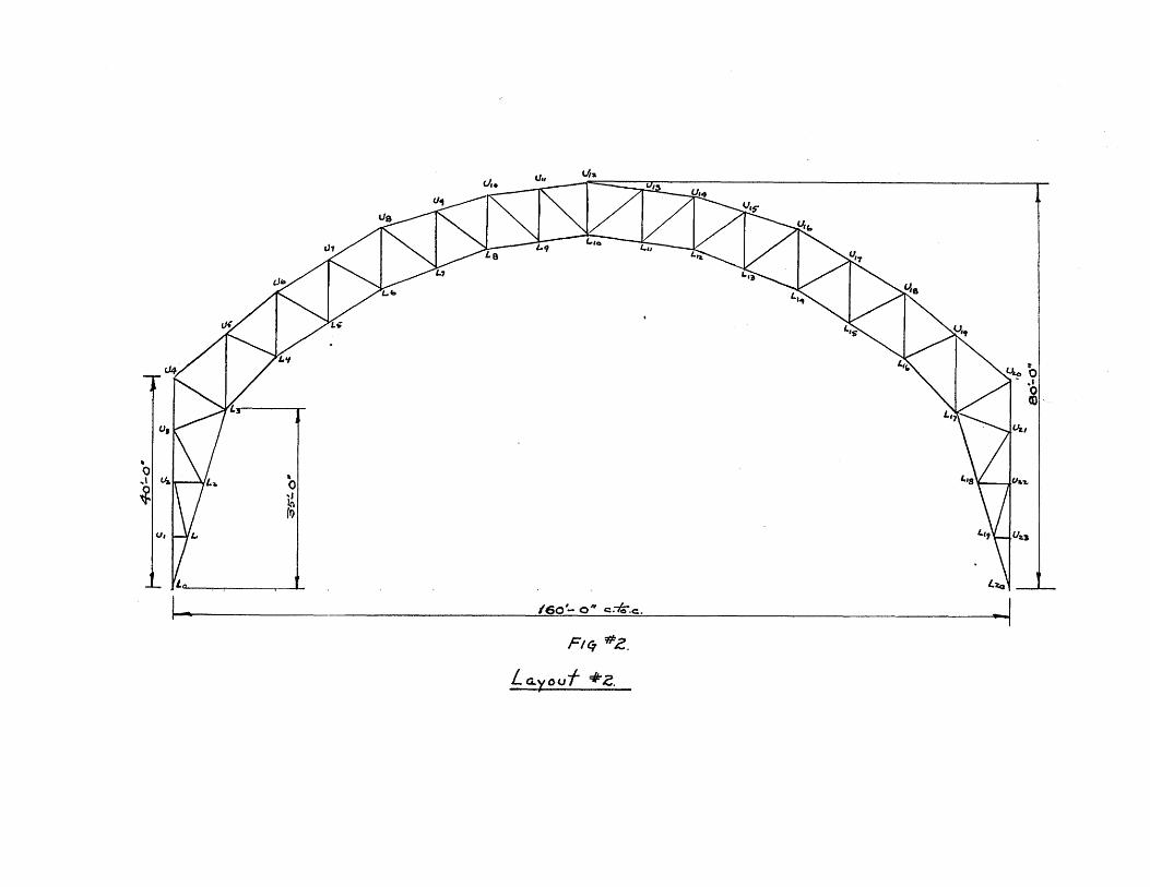
IV. Layout of Arch:
The layout of the truss was governed by the given
span (1601) and by clearance requirements, it being required
to get the maximum height inside the building for the great-
est possible width. This led to the adoption of a truss
shallower at U4 - L3 than called for by consideration of
economy.
The arches will be spaced at 4o'-O". This figure
was taken after a consideration of roof arches which already
have been built.
The layout first considered was as shown in Fig.
#1 and this was eliminated in favor of the layout shown in
Fig. #2. In the second layout it will be noticed that the
chords are run straight for two panels thus eliminating

splices and requiring only one half the number of trussed
purlins. Also, it will be noticed that the arch was con-
siderably deepened by making the bottom chord a parabola
from L3 to L10. This deepening of the arch made it a great
deal stiffer and was shown up in Williot diagrams drawn for
the two cases.
V. Design of Roof;
1. - _Tye of Roof
A roof for this structure should have as
many of the following requirements as possible:
1. Long life
2. Economical
3. Ease of construction
4. Light in weight
5. Satisfactory on steep slope
6. Fireproof
7. Good insulator
5. Allowances for expansion and contrac-
tion
The type of roofing which meets these re-
quirements in a satisfactory manner is steel plate
roofing and is suppli'ed by various manufacturers.
That manufactured by the Truscon people weighs 5#
per sq. ft. of roofing surface, which includes in-
sulation and waterproofing. This type of roofing
was used in the building of the Maple Leaf Gardens,
Toronto, Ont. (The Engineering Journal, March 1932).

The following information is supplied re-
garding the Truscon roof:
Live load - # per sq. ft; Spans18 ga. 20 ga.
45 61-7"1 5'-1
4o 7'-01" 6'-o"
35 7'-61 61-4"
30 .'-O" 6'-lo"
25 8'-5'' 7'-61
20 9'-6" 8'-2"
Note: Dead load is provided for.
2. - Roof loads
Ice and show loads are vertical loads and
the wind load is perpendicular to the roof surface.
In order to find the load perpendicular to the roof
surface, per sq. ft., so that we may be able to de-
cide on the proper gauge and span of roofing to use,
it will be necessary for the snow and ice loads to
be resolved in a direction perpendicular to the roof
surface. This can be done by multiplying these loads
by the cos a, where "a" is the inclination of the
roof at the section under consideration.
3. - Selection of Roofing
Section U4-u6:
Slope 41.50 deg.
Ice Load = 10# per sq. ft. = 10 x .7492. = 5.60
Wind Load = 27.90
Total 33.10# per sq. ft.

e8
Section U6-Ug:
Slope-32.0O deg.
Ice load - 10# per sq. ft. = 10 x .848 = 7.20
Wind load = 24.50
Total 31.70# per sq. ft.
Section U8-U1o:
Slope-20.50 deg.
Snow load = 25# per sq. ft. = 25 x .936 21.9
Wind load 9.2
31.1# per sq.ft.
Section UlO-U12
Slope-70.0O deg.
Snow load 25# per sq. ft. = 25 x .99j- 24.5
Wind load=
28.0# per sq.ft.
Therefore, use 18 guage roofing, maximum spacing 7'-6".

-S.4A4 -o b uI ->
A-9 9_ J
1o
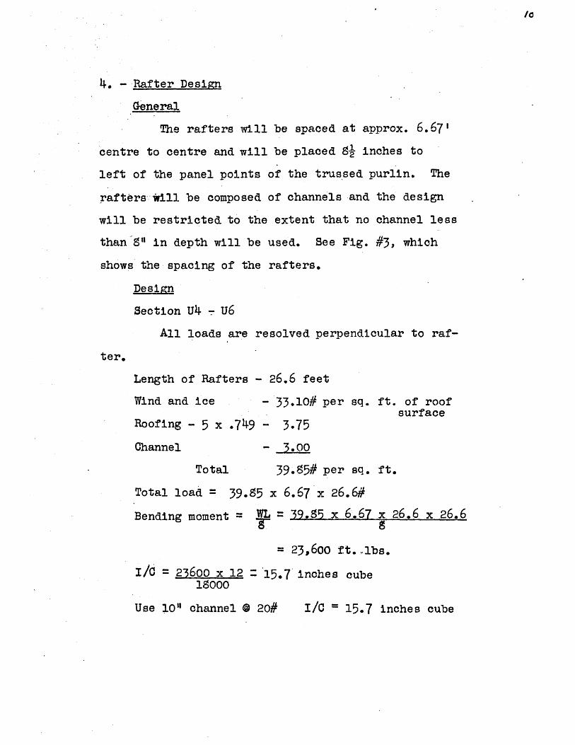
4. - Rafter Design
General
The rafters will be spaced at approx. 6.67'
centre to centre and will be placed 8} inches to
left of the panel points of the trussed purlin. The
rafters *ill be composed of channels and the design
will be restricted to the extent that no channel less
than 8" in depth will be used. See Fig. #3, which
shows the spacing of the rafters.
Design
Section U4 - U6
All loads are resolved perpendicular to raf-
ter.
Length of Rafters 26.6 feet
Wind and ice - 33.10# per sq. ft. of roofsurface
Roofing - 5 x .749 - 3.75
Channel -300
Total 39.5# per sq. ft.
Total load 39.5 x 6.67 x 26.6#
Bending moment = WL = 39.895 x 6.67 x 26.6 x 26.6
= 23,600 ft. .lbs.
I/ 23600 x 12 15.7 inches cube18000
Use 10" channel @ 20# I/C = 15.7 inches cube
If
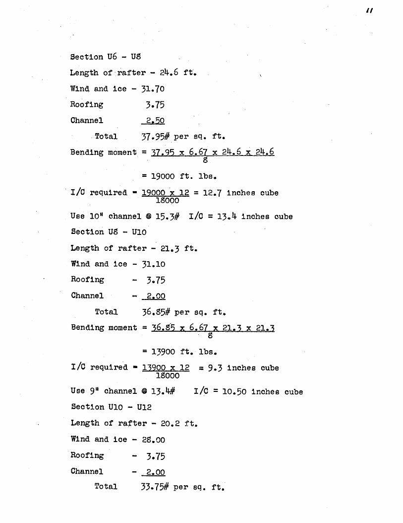
Section U6 - U8
Length of -rafter - 24.6 ft.
Wind and ice - 31.70
Roofing 3.75
Channel 2,70
Total 37.95# per sq. ft.
Bending moment = 37.95 x 6.67 x 24.6 x 24.6S
19000 ft. lbs.
I/C required - 19000 x 12 = 12.7 inches cube18000
Use 10" channel @ 15.3# I/C = 13.4 inches cube
Section U8 - U10
Length of rafter - 21.3 ft.
Wind and ice - 31.10
Roofing - 3.75
Channel 2.00
Total 36.85# per sq. ft.
Bending moment = 36.S5 x 6.67 x 21.3 x 21.38
= 13900 ft. lbs.
I/C required - 13900 x 12 = 9.3 inches cube18000
Use 9" channel @ 13.4# I/C = 10.50 inches cube
Section U10 - U12
Length of rafter - 20.2 ft.
Wind and ice - 28.00
Roofing - 3.75
Channel - 2.00
Total 33.75# per sq. ft.

"C.
~23
070
~
IC)
N
p
'I' N

Bending moment 33.75 x 6.67 x 20.2 x 20.2
11500 ft. lbs.
I/C required 11500 x 12 7.65 inches cube18000
Use 8" channel @ 11.5# I/C = 8.1 inches cube
VI. Design of Trussed Purlins.
The purlin at US will be designed and the remain-
der of the purlins will be composed of the same sections.
The reason for this is that little difference would result
in the design anyway and furthermore the design of the
bottom and top chords are limited by slenderness ratios,
and also this is the worst case.
Loads See Fig. #4.
Load on purlin from bay U6 - U8, per panel
Snow ,- S.45# per sq. ft. = 8.48 x 6.67 x 20 = 1030
Dead - 5.00# " " " = 5.00 x 6.67 x 23.6- 78
Wind - 24.50# " " " =24.50 x 6.67 x 23.6= 3850
Purlins- 24.6 x 15.3
Total 6045#
per panel
Load on purlin from bay U8 - U10, per panel
Snow - 23.4# per sq. ft. = 23.4 x 6.67 x 20 = 3160
Dead - 5.0# " " " 5.0 x 6.67 x 21.3= 709
Wind - 9.2# " " " = 9.2 x 6.67 x 21.3= 1305
Purlins- 13.4 x 21.3 286
Total 5460#
per panel

. . Panel load = 5460 plus 6045 = 5720#2
dead (assumed) = 6oo#
Bracing (at centre) = 1500#
The Stress Analysis is shown in Fig. #4,
Design of Members
Bottom Chord
The bottom chord is unsupported laterally for
401-O" and although this is a tension member, it
also acts as a strut between the trusses. 2 angles
6 x 3-1/2 x 5/16 0 9.S#, area 5.74 sq. in., with the
short legs back to back give a slenderness ratio of
4o x 122.90 165, which is reasonable.
Top Chord
The top chord while it is supported laterally
when the building is completed, acts as an unbraced
strut during erection. Also we need a fair size to
have a good seat for the rafters. Use 2 angles,
5 x 3'x 5/16, 0 S.2#, area 4.80 sq. in.
L 40 x 12 198R2.42
Verticals
Max. Stress -23070#
L- must be less than 120
Try 2 angles, 3-1/2 x 3 x 5/16
L = 11.4 x-12 = 124 greater than 120R 1.11

/6s
// -5
4u~
t
0
i

/6
Try 2 angles, 3-1/2 x 3-1/2 x 5/16
R 3r1.09 126, greater than 120
Try 2 angles, 4 x 3-1/2 x 5/16 @ 7.7#
L 1 x 12R .1.26 * 109, less than 120
Therefore, use 2 angles, 4 x 3-1/2 x 5/16 @ 7.7#,
area = 4.50 sq. in., for the verticals throughout.
Fig. #5 shows the section and areas used.
Note: The rafters were put gi" off centre for pur-
poses of spacing. The load however will come into
the joint as it will be over the gussett plate and
will not cause bending of any magnitude.
Diagonals
Max. Stress = (plus) 19,500
Net area required - 19800= 1.10 6q. in1S000 =11 q n
Rivet holes = 7/9 x 5/16 . " "
Total 1.37 " "
Use 1 angle, 3 x 3 x 5/16 @ 6.1#, area - 1.78 sq. in.

5 bpys e 40'.zoo'-.-
ic 4r7 6.
C'e-riev-a./ of bra.c-rn a-r-d yfS

/s
Calculation of Weight of Purlin
Member
Ul - U2
- U3
- L2
- L3
-L2
-.L3
-L4
-L2
U3 - L3
Description
2 an
2
2
2
2
2
1
1
1
2
2
an
gles 5 x 3 x 5/16
5 x 3 x 5/16
" 5 x 3 x 5/16
6 x 3-1/2x 5/16
6 x 3-1/2x 5/16
6 x 3-1/2x 5/16
gle 3 x 3 x 5/16
3 x 3 x 5/16
3 x 3 x 5/16
" 4 x 3-1/2x 5/16
0 8.2
0 8.2
o 8.2
a 9.8
o 9.8
0 9.8
o 6.1
@ 6.1
a 6-1
@ 7.7
x
x
x
x
x
x
x
x
x
x
6.67'
6.67'
6.67'
6.67'
6.67'
6.67'
13.2'
13.2'
13.2'
11.4'
Weight
109.5
109.5
109*5
12.5
128.5
128.5
80.5
so.5
0.5
176.o
" 4 x 3-1/2x 5/16 0 7.7 # x 11.4' 176.0
1307.5x 2
2615.00
U4 - L4 2 " 4 x 3-1/2 x 5/160 7.7 # x 11.4' _;1 6 ,200Total 2791.00Details - 20% 560.oo
Total 3351.00
Assumed weight = 3600#, which is satisfactory.
VII. Design of Lateral Bracing:
The lateral bracing will be designed to carry the
the wind load on end of building and the diagonals will be
tension members only. One expansion unit will consist of
five bays, 5 x 40 = 200 feet, of which two are braced bays.
For general layout of bracing system, see Fig. #6.
U2
U3
Li
L2
L3
Ul
U2
U3
U2

Fie '7
-e v~a. 4 e's. c 77 - -Io - /71-r7j ecI :L-- A7.
~0
£4 U 4 ,'(4T
0=10
L~J
-i i;J~
Design
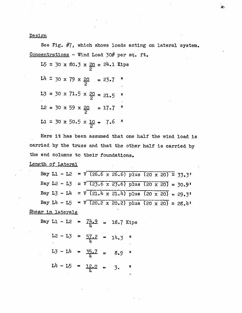
See Fig. #7, which shows loads acting on lateral system.
Concentrations - Wind Load 30# per sq. ft.
L5 = 30 x 80.3 x 20 = 24.1 Kips2
L4 ~ 30 x 79 x L.Q2
= 23.7 "
L3 = 30 x 71.5 x 2 1 "2
L2 = 30 x 59 x 202
= 17.7 "
L1 30 x 50.5 x 10u 7.6 "2
Here it has been assumed that one half the wind load is
carried by the truss and that the other half is carried by
the end columns to their foundations.
Length of Lateral
Bay Ll - L2
Bay L2 - L3
Bay L3 -L4 =
Bay L4 -L5
Shear in laterals
Bay Ll - L2 =
L2 - L3 =
L3 - L4 =
L4 - L5 -
V (26.6 x
V (23. 6 x
V (21.4 x
V (20.2 x
26.6) plus (20 x 20) 33.3'
23.6) plus (-20x- 20) =30.9'21.4) plus (20 x 20) 29.3*
20.2) plus (20 x 20) =28.4'
SS.7 Kips
. 14.3 n
= S.9 "I
3.."12.04
Stress in Laterals
Bay Ll - L2 19.7 x 33.30-20
L2 - L3 = 14.3 x 309=20
L3 - L4 = 8
L4 - L5 = 3
.9 x 29.3 =20
x20
31.2 Kips
22.0 "
13.0 "
4.25 "
Areas Reauired
Rivet Holes
Bay Li - L2
Bay L2 - L3
Bay L3 - L4
Bay L4 - L5
2 x x 1 -n
31.2 plus
220 plus
i3.0 plus18
15 plus
.625 sq.
.625=2.36
.625=1.55
.625=1.35
.625= .56
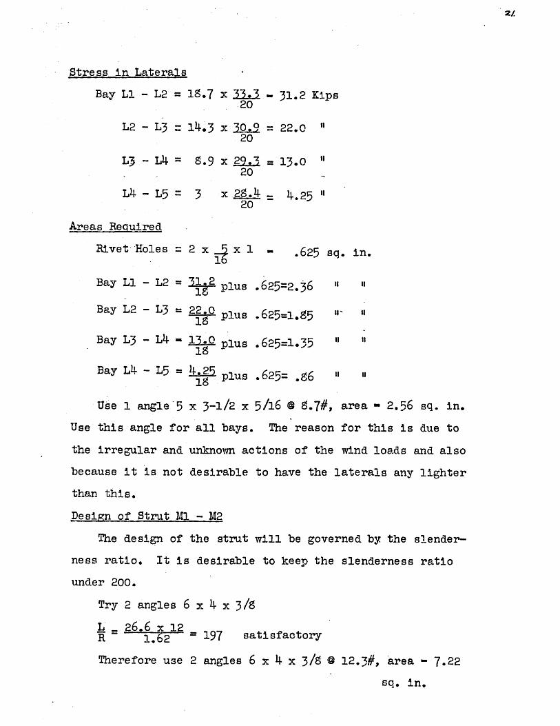
Use 1 angle'5 x 3-1/2 x 5/16 @ 8.7#, area - 2.56 sq. in.
Use this angle for all bays. The reason for this is due to
the irregular and unknown actions of the wind loads and also
because it is not desirable to have the laterals any lighter
than this.
Design of Strut M1_ - M2
The design of the strut will be governed by the slender-
ness ratio. It is desirable to keep the slenderness ratio
under 200.
Try 2 angles 6 x 4 x 3/8
L - 26 .6 x 12R 1.62 197 satisfactory
Therefore use 2 angles 6 x 4 x 3/5 @ 12.3#, area - 7.22
sq. in.
2z
in.
II ii
II- Ii
II II
I, II

22.
Calculation of Weight of Bracing
No. of feet of diagonals = 8(33.3 plus 30.9 plus 29.3plus 28.4) = 975.2 ft.
Weight per foot = 8.7#
Weight of diagonals 8.7 x 975.2 = 8500#
No. of feet of strut 2(26.6 plus 23.6 plus 21.4 plus
20.2) = 183.6 ft.
Weight per foot 12.#
Weight of struts 12.3 x 183.6 = 2260#
Total weight = 8500 plus 2260 - 10760#
Details, 15%,(including tie rods) 1610
Total 12370
Design of Sway Bracing
Shear in laterals -2.5 - 41.25 Kips2
Req'd net area 41.25= 2.30 sq. in.18. 00
Rivet holes= 2 x 3/8 x 1 . "
3.05 "
Use 1 angle 5 x 3-1/2 x 3/S i- 10.4#, area = 3.05 sq. in.
Weight of sway bracing = 4 x 10.4 x 50 = 2090#Details, 15% lo00#
Total 2180#
Design of Girts
The girts will be channels and will be spaced at 7.51
down the sides centre to centre. They will be held at
9' intervals by sag rods which are suspended from the end
trussed purlin. The chanhels will have their edges perpen-
dicular to the ground.

23.
Length of girt =40'-O"
Uniform load (parallel to ground) 7.5 x 40 x 30
9000#
Uniform load (perpendicular to ground)
Weight of covering - 7.5 x 40 x 5 1500#
Dead-load= 35 x 40 - 1400#
Total 2900#
B. M. parallel to ground 2000 x 40 = 45,000 ft. lbs.
I/C required = 45000 x-12 = 3018000
Use 1 12" channel @ 40# I/C 32.5 Axis 1 - 1
S due to M = Mc. = 45000 12 x 6 = 16,500# per sq. ft.I 196.5
Tie rods will take the load perpendicular to the ground.
Use }" round rods, spaced at 5' centre to centre.
Weight of girts 6 x 40 x 4o = 9600#
Rods -42x7.5x. 668 = _210#
Total 9510#
Calculation of total weight of bracing and girts per bay
Weight of lateral bracing = 12370#
sway " 2150#
" girts -g910#
24360#
.*. Weight per truss = 12180#, call 12000#
This weight will be added to the dead weight of the
truss for the purposes of stress analysis and will be as-
sumed to act uniformly over the truss.

Calculatibn ofvight of roof without purlins and bracing
Area of roof, one side = (26.6 plus 23.6 plus 21.4
plus 20.2) 40 = 3680 sq. ft.
Weight of covering = 3680 x 5 = 18400#
Purlins 6 x 26.6 x 20 = 3220
6 x 23.6 x 15.3 = 2260
6 x 21.3 x 13.4 - 1720
6 x 20.2 x 11.5 1390
26990#
Weight per so. ft. of roof = 269903680 7.35# per sq. ft.
VIII. Calculation of Panel Loads:
Weight of truss - 48006#
The loads due to the weight of the truss and brac-
ing, together with the roof, will be distributed as shown
in Drawing #4.
Purlins.
The weight of purlins will be taken as 3400#.
Roof
The weight of the roof will be taken as calculated;
i.e., 7.35# per sq. ft. of roofing surface. The weight of
the roof and purlins on combination with weight of truss
and bracing are shown in Drawing #4.
Roof Loads at tanel points
At U4-
7.35 x 13.3 x 40 3920#
purlin = 3400
Total 7320#

25
At U6
7.35 x (13.3 plus 11.9) 4o = 7350#
purlin
Total
= 3400#
10750#
At U8-
7.35 x (11. plus 10.7) 40 = 3050#
Purlin
Total
= 3500#6550#
At U10-
7.35 x (10.7 plus 10.1) 4o = 2600#
purlin -0#
Total 6loo#
At U12-
7.35 x (10.7 plus 10.1) 40 = 2600#
purlin
Total
3500#
61oo#
Snow Loads - 25# per sq. ft horizontal projection.
At u4 - Slope - 41.50 degs.
Snow load = 10# per sq. ft. horizontal projection
. . load = 10 x 40 x 1o = 4ooo#
At U6 - Slope 41.50 degs. and 32 degs.
Snow load 11.5# per sq. ft horizontal projection
. * load = 11.5 x 40 x 20,= 9200#At US - Slope - 32 deg. and 20.50 deg.
Snow load 19# per sq. ft. horizontal projection
. . load = 19 x 40 x 20 ~- 15200#
At U10 - Slope 20.50 deg. and 7 deg.
Snow load = 25# per sq. ft. horizontal projection
- 25 x 40 x 20 m 20,000#.'. load

At U12 - load = 20,000#
Snow loads are shown in Divg. # 5.
Wind Loads
The wind load is applied to
formulae and then it is resolved
vertical components for purposes
also for ease
are drawn for
Panel Anglepoint
U1 -
U2 -
U3 -
U4 -41.50
u6 41.5032.00
U8 32.0020.50
Ulo 2.507900
U12 7. 00
deg.
"t
"
"
"
"
"
"
the roof using Duchemin's
into its horizontal and
of stress analysis, and
in applying it to the influe.nce lines which
horizontal and vertical loads.
Loadlbs. perscq. ft.
30
30
30
3027.5
27.524.5
24.18.: &
18.47.00
7.oo
Areasq. ft.
4oo
400
400
200532
70
470424
4244oo
Total loadperp toroof (lbs.)
12000
12000
12000
6ooo146oo
146oo11500
1150078oo
7002S00
2800
horizontal verticalcomponent component
12000
12000
12000
6ooo(9650
(965061oo
6100(2720
2720(2340
340
10,900
(10,9009,750
9,750(7,.300
7,30o(2,780
2,790

Total horizontal and vertical loads at the panel points
due to wind.
Panel Horizontal Verticalpoint load in lbs. load in lbs.
U1 12000 0
U2 12000 0
U3 12000 0
U4 15650 10900
U6 15750 20650
U8 $820 17050
U10 3060 10080
U12 340 2780
Wind loads are shown on DIVg. # 7.
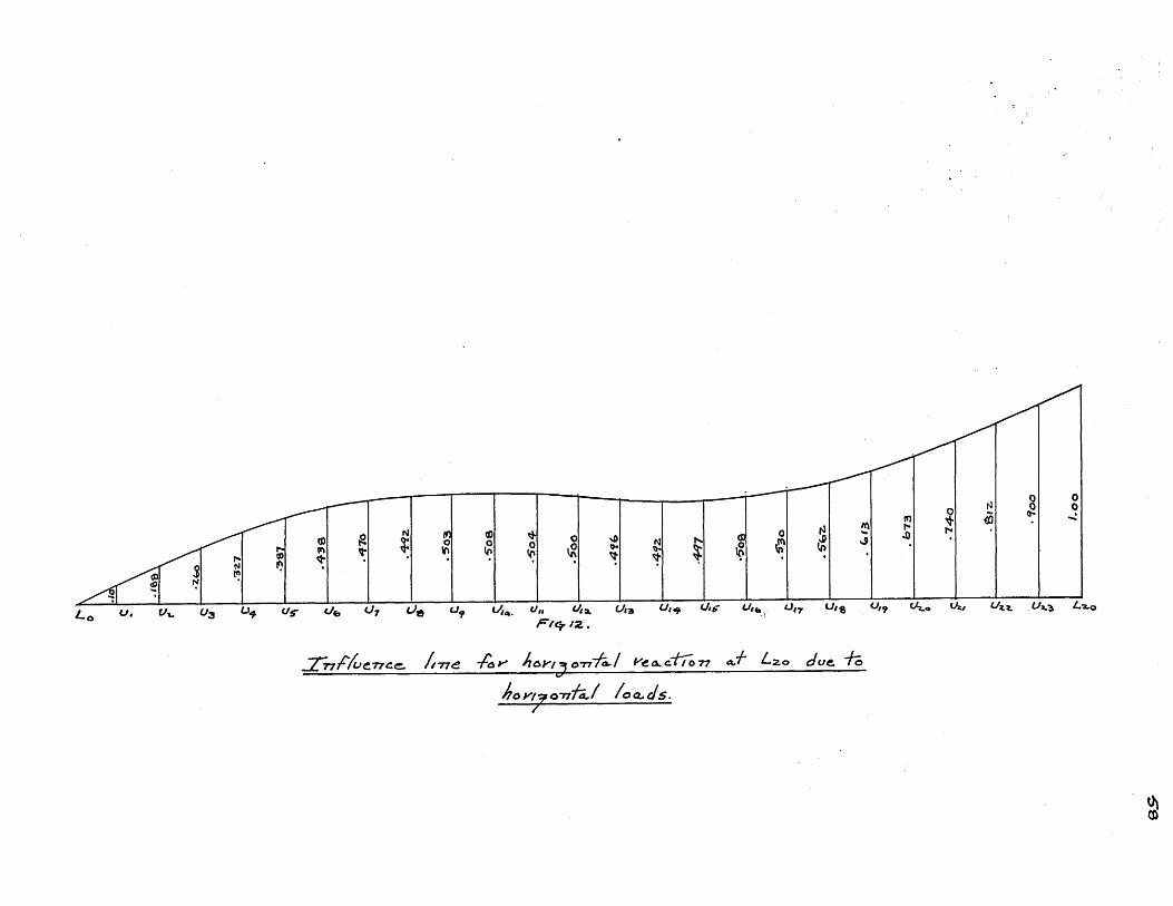
IX. Design of-Arch:
1. General
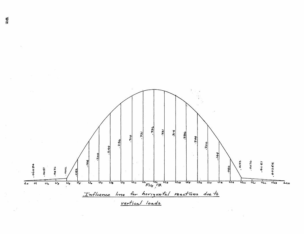
First the influence lines were drawn (Figs. #12
and #13) for the redundant horizontal reaction as
previously explained. Then the horizontal reactions
were calculated from these influence lines for the
following different loadings; Dead load, snow all
over, snow right, wind right. Of course, snow left
for example and snow right will give the same re-
sults as the arch is symmetrical in all respects.
After the horizontal reactions were calculated for
the above conditions of loading a stress analysis
was done for each case. These drawings are marked
4, 5, 6, and 7, respectively. Drawing #1 shows the
00
6o~4
006T
I
0Io
-z~ .
(Oz-
.0076
.00
26
4t
a p ~aI
28
.
H :1 -'I 0 ~Jh
C' 0 P
f%.

:Z
NNl6
ab
a'
S Z
dimensions and lengths of the various members.
Drawing #2 is a stress analysis for condition
Xa =. -1, the results of which were used in the
drawing of the Williot diagram (Drawing #3).
Drawing #8 is a stress analysis for condition
Xa 0, for the snow loading. This was done to
check the graphical work of the Williot diagram.
Drawing #9 is the Williot diagram using the de-
signed areas. Drawing #10 shows an outline of the
truss with the final sections marked on it, and
their areas.
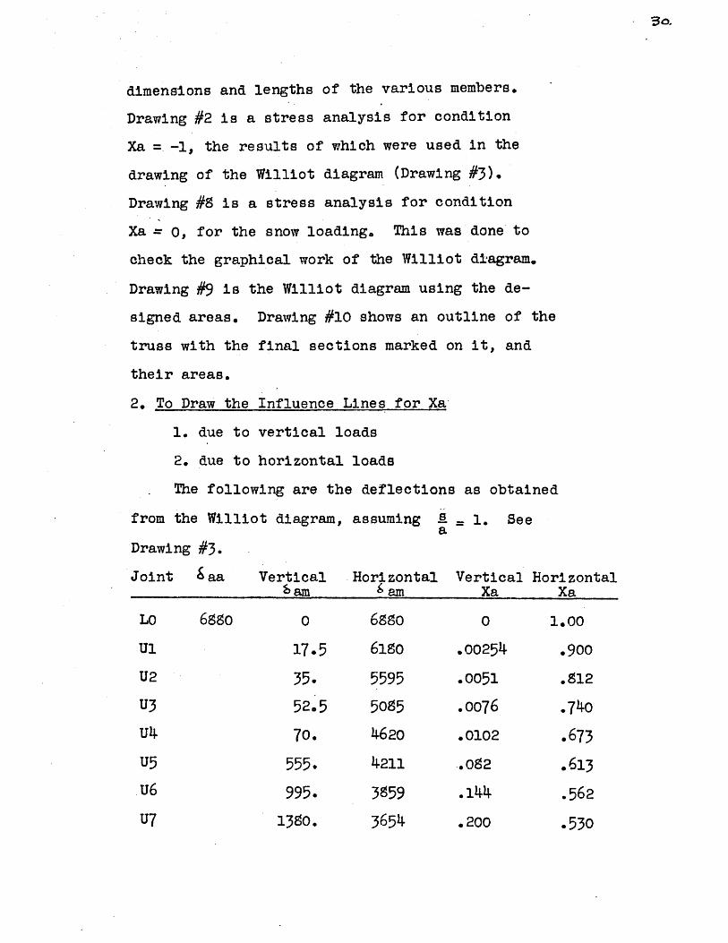
2. To Draw the Influence Lines for Xa
1. due to vertical loads
2. due to horizontal loads
The following are the deflections as obtained
from the Williot diagram, assuming A 1. Seea
Drawing #3.
Joint Saa Vertical Horizontal Vertical Hor
68oLO
U1
U2
U3
U4
U5
U6
U7
am
0
17.5
35.
52.5
70.
555.
995.
13o.0
6 am
6980
618o
5595
5085
4620
4211
3859
3654
Xa
0
.00254
.0051
.0076
.0102
.02
.144
.200
izontalXa
1.00
. 900
.812
.740
.673
.613
.562
.530

Joint Saa
U8
U9
Ulo
Ull
U12
U13
U14
U15
u16
U17
U18
U19
U20
U21
U22
U23
L20
VerticalSam
1715.
1970.
2160.
2280.
2310.
2280.
2160.
1970.
1715.
1380.
995.
555.
70.
52.5
35.
17.5
0
3. To calculate the horizontal reactions due to the
following vertical loads:
1. Snow
2. Dead (weight of truss and roof, and bracing).
3/
Hor zontall am
3484
3414
3384
3409
3440
3475
3500
3460
3380
3240
3020
266o
2250
1790
1290
688
0
VerticalXa
.249
.286
.314
.331
.336
.331
.314
.286
.249
.200
.144
.082
.0102
.0076
.0051
.00254
0
HorizontalXa
.,508
o497
.492
.496
.500
.504
*508
.503
.492
.470
.438
.327
.260
.188
* 100
0

Point VerticalCoeff'.
Dead ReactionLoad due to
dead load
Snow ReactionLoad due to
snow load
Lo 0
Ul .00254
U2 .0051
U3 -. 0076
U4 .0102
U5 .082
U6 .144
U7 .200
US .249
U9 .286
Ulo
Ull
U12
.314
- 331
*336
0
6ooo
66oo
66oo
10520
26oo
13350
26oo
9150
26oo
8700
26oo
4!350
0
15
34
50
107
213
1925
0
0
0
0
4ooo
0
9200
520 0
2250 15200
745 0
2730 20000
861 0
146 10000
75670# 109402
21880#
0
0
0
.0
0
1325
0
3755
0
6290
0
3360
5840o# 147902
29580#
Horizontal reaction for snow one side = 14,790#
"3Z

4. To calculate the horizontal reactions due to wind one
Horz. Reaction Vert.load due to load
Horz. Load Coeff.
side:
Point Horz.LoadCoeff.
1.000
.900
*812
*74o0
.673
.613
.562
.530
* 508
.497
.492
.496
*500
0
.00254
.0051
.0076
.0102
-082
.144
.200
.249
.286
.314
.331
.336
Vert. Reactionload due to
Vert. Load
0
0
0
0
10900
0
20650
0
17050
0
10080
0
2780
0
0
0
0
111
0
2980
0
4240
0
3140
114o6#
Consider wind blowing from the right, then right re-
action will be opposite to the wind and equal to 54,990 -
11,406 43,584#, and the left reaction = 11,406 plus
(79,620 - 54,990) = 36,036#.
0
10800
9750
10550
0
8850
0
4480
0
1510
0
170,
54990#
LO
Ul
U2
U3
U4
U5
U6
U7
U8
U9
Ulo
Ull
U12
0
12000
12000
12000
15650
0
15750
0
8820
0
3060
0
340
79620#

5. Calculation of Maximum Stresses (All figures are plus except those marked - )
Member Dead Snow All Snow WindRight Left Right Left
LO - Ul
U1 - U2
U2 -.U3
U3 -U4
u4 - U5
U5 - U6
u6 - U7
U7 - U8
U8 - U9
U9 -lo
Ulo-Ull
Ull-U12
LO - L1
L1 - L2
L2 - L3
L3 - L4
L4 - L5
.91
6.91
13.51
20.11
29.60
7.66
- 6.44
-19.20
-26.90
-34.8o
-37.10
-39.00
-79.70
-79.70
-79.70
-60.30
-34.oo
45.13
45.13
45.13
45.13
47.50
22.4o
- 1.79
-26.8o
-42. 4o
-62.50
-65.80
-72.17
-107.50
-107.50
-107.50
- 89.10
- 57.10
34.31
34.31
34.31
34.31
33.15
30.80.
22.75
17.35-
5.62
- 5.58
-20.60
-36.40
-54.oo
-54.0
-54.0
-54.20
-46.70
10.81
10.81
10.81
10.81
14.35
- 8.45
-24.50
-44.20
-48.oo
,57 .10
-45.30
-36.40
Maximum(plus)
106.26
112.26
118.86
125.46
135.35
104.66
8o.16
68*30
40.50
19.40
94.54
94.54
94.54
94.54
91.40
97.00
86.6o
87.50
67.4o
54.20
25.80
.50
-182.39
-182.39
-161.39
-128.39
91.14
-103.54
-112.74
-105.17
- 89.56
- 62.58
- 33.47- 16
158.50
137.00
115.O0
113.20
117.20
- - -t"
78.80
57.30
35.30'
52.90
83.20
-54.0 -131.00
-54.0 -131.00
-54.o -131.00
-34.9 -142.50
-10.35-134.20
vi
Maximum(minus)
s 181.48
. 175.48
s 147.88
a 10.28
a 61.54
95.88
119.18
124.37
116.46
102.96
102.90 s
111.17 8
264.70 s
264.70 s
264.70 s
237.70 s
178.55 S

Snow All
L5
L6
L7
L9
L9
U1
U2
U2
U3
U3
U4
U5
U5
U6
U6
U7
U7
- L6
- L7
- L8
- L9
-L10
- Li
- Li
- L2
- L2
- L3
- L3
- L3
- L4
-L4
-L5
-L5
-L6
Member
-20.15
- 6.14
3.57
10.25
15.20
0
0
0
0
0
-25.60
-24.4.1
18.10
-28.65
13.15
-14.7
12.10
Dead Maximum(Olus)_
-34.50
- 7.46
11.00
29.10
35.90
0
0
0
0
0
-4o.o
-24.95
20.60
-36.02
21 * 50
-24.21
23.80
Right
-41.0
-32.CC
-21.7c
- 9.7c
5.74
0
0
0
0
0
-28.00
- 2.37
1. 9
-10.6
4.*5
- 5.1
5.0
Maximum(minus)
SnowLef t
7.35
24.60
32.0
38.90
30.30
0
0
0
0
0
-12.15
-22.62
5 18.65
2 -25.37
5 16.,85
T -19.04
7 18.75
Right
-134.7
-120*C
-107.5
- 97.6
- 62.2
0
0
0
0
0
- 77.5.
- 17r
- .4
.4
- .
WindLeft
0 109.20
0 68.20
61.6o
0 30.20
0 - 2.25
-12.00
21.90
-19.00
23.40
-26.90
00 94.50
6o -16.39
61 13.50
61 3.46
61 - 7.69
64 g .65
69 - 9.52
34.65 s
39.08 S
35.90 s
99.05
62.06
65.17
49.15
51.10
21.90
23w4o
58.90- -" -
39.70- - -ft
154.85
126.14
103.93
77.35
s 47.00
12.00
0- - -
18.00
26.90
114.75 S
49.36 s
- - -m
s
71.63 8
- - -M
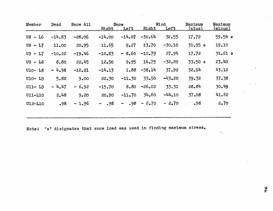
Snow All
U8 -L6
U9 -L7
U9 -L7
U9- L8
Ulo- L9
UlO- L9
Ul- L9
Ull-Lio
U12-Llo
Right
-14.83
11.00
-10.22
980.
- 4.9S
5.82
- 4.47
20.48
.98
SnowLeft
-28.06
20.95
-19.46
22.45
-12.21
9.00
- 6.92
9.20
- 1.96
RightWind
-14.0oo
11.65
-10.83
12.50
-14.1320.30
-15.70
20.90
- 0.8
Left
-14.o7
9027
- 8.6o
9.95
-11.30
8*8o
-11.70
- .98
Maximum(Dlus)
-30.64
13.70
-12.o79
14.75
-38.14
33.50
-26.02
34.60
- 2.70
Maximum(minus)
32.55
-30.10
27.94
-32.20
37.92O-43. 20
33.31
-44.1 o
- 2.70
Note. "Is" disignates that snow load was used in finding maximum stress.
W
Member
17.72
31.95
17.72
33.50
32.94
39.32
37.09
.95
Dead
59.54
8 19.10
31.61
s 23.40
43.12
37*38
30.49
41.62
2070
s
S

~-7j
6. Temperature Stresses in Arch
The arch will be considered subjected to an increase
of 60 deg. F. or a decrease of 80 deg. F. An increase in
temperature will cause the reactions to act inwards or in
the opposite direction to assumed direction of Xa -1,
while a decrease in temperature will cause the reactions
to act in the same direction as Xa = -1.
We have Xa -7.. -tL
The following constants will be assumed:
E - 30 x 10 # per sq. in.
e = 6.5 x lCF
For an increase of 6o deg. F.
gat = etl = 6.5 x 10'x 6o x 160 x 12
Saa = 68.80 x 2-x-10 x 1230,000,000
Xa = 6.5 x 10 x 6o x 16o x 12 x 30,000,00068.80 x 2 x 10 x 12
= 1358#
For a decrease of 80 deg. F.
6 at - 6 .5 x l0~x g0 x 160 x 12
Saa - 68.90 x 2-7, 10 x 1230,000,000
Xa = 6. x 10~ x 80 x 160 x 12 x 30,000,0006:8.80 x 2 x 10 x 12 86
Note6 The deflection -aa from the Williot Diagram was
68.60" and the scale was 1/10" = 2 c 12 ". Therefore30,000,000
Saa -- 10 x 2 - 12 x 68.80 inches.30,000,000

-38
To arrive at the temperature stresses in the various
members, the stress in that member due to Xa = -1 is mul-
tiplied by the horizontal reaction due to temperature, the
sign being changed in the case of an increase in temper-
ature.
Temperature stresses were not added to the maximum
stresses in the various members when the temperature stress
to be added was due to an increase in temperature and the
maximum stress in the member was partly due to snow load.
In the calculation of Xa by algebraic summation due
to snow there appears the summation Saa, which equals
1375.67.
Calculating the reactions due to temperature by this
method, we get
For increase-of 60 deg,
Xa = 6.5 l 10~ 6o x 160 x 12 x 30,000,000 = 1360#1375.67 x 12
For decrease of 80 de&.
Xa = 6.3 x lO x 80 x 160 x 12 x 30,000,000 = 1815#1375.67 x 12
As can be seen this gives a perfect check with the
Xa as found by the Williot diagram.

7. Calculation of temperature stresses and total stresses. (All figures are
plus except those marked -
Member Increase DecDlus 6o Min
Lo -
U1 -
U2 -
U3-
U4 -
U5 -
u6 -
U7 -U8 .
U9 -
Ulo-U11-
LO -
L1 -
L2 -
U1
U2
U3
U4
U5
U6
U7
U8
U9
UlO
Ull
U12
L1
L2
L3
4.76
4.,76
4.76
4.76
4.6o
6.05
6.70
8.25
8.40
9.42
9.15
- 9.52
4.95
- 4.95- 4.95
)
rease.s 80
6.35
- 6.35- 6.35
- 6.35
-6 63
- 8.07
8.92
- 11.05
- 11.20
- 12.57
- 12.30
- 12.73
6. 6o
6. 6o
6. 6o
Maximum(nlus)
106.26
112.26
118.86
125.46
135.35
104.66
80.16
68.30
40.50
19.,0
78.80
57.30
35.30
:-0
Maximum(minus)
S 181.48
s 175.48
s 147.s8
S 108;28
5 61.54
95.s8
119.18
124.37
116.46
102.96
102.90
111.17
264.70
264.70
264.70
Total
106.26
112.26
118.86
125.o46
135.35
110.71
86.86
76.55
4 .io
28.82
5 9.15
5 9.52
s 85.40
s 63.90
s 41.90
Total(minus-)
187.83
181.83
154.23
114.63
67.67
103.95
128.10
135.41
127.66
115.53
115.20
123.90
264.70
264.70
264.70

Member
L3
L4
L5
L6
L7
L8
L9
U1
U2
U2
U3
U3
U4
U5
U5
u6
U6
U7
- L4
- L5
-L6
- L7
- L8
-L9
- L10
- L1
-Li
-L2
-L2
-L3
-L3
-L3
-L4
-L4
-L5
-L5
Increaseplus 60
6.56
- 7.27
- 8.65
-9.05
10.00
-10.20
10.55
0
0
0
0
0
3.86
1.45
1.19
.24
- 1.30
1.50
Decreaseminus g0
9.75
9.70
11.55
12. 6o
13.35
13.60
14.05
0
0
0
0
0
5.15
- 1.94
1.59
.32
1.74
2.00
Maximumeplus)
52.90
83.20
89.05
62.06
65.17
49.15
51.10
21.90
23.40
- -
55.90
18.00
26.90
114-75
49-36
71.63
- - -.
39.08
S
23.40
B 64.05
8 1.4-5
40.29
s .24
36.39
5 . 1.50
26.90
114.75
51.30
- 1.19
71.95
1.30
41.05
38.70 6- - -.
34.65-m -M -m
Maximum(minus)
237.70
178.55
154.85
126.14
103.93
77.35
47.00
12.00
Total(Plus)
S 60.65
S 92.90
100.60
74.66
78.52
68.75
65.15
- -" -m
Totalinugs
237.70
175.55
163.50
135.19
113.93
57.55
57.55
12.00
21.90

Member
U7 - L6
U8 - L6
U8 - L7
U9 - L7
U9 - L8
U10-L8
Ulo-L9
U11-L9
Ull-L10
U12-L1O
Increaseplus 6o
- 1.47
- .50
- 1.08
1.01
- 1.15
- .49
.34
.45
- 2.37
Maximum(minus)
Decreaseminus 80
1.96
1.07
1.43
- 1.34
1.54
2.45
.65
- .45.6o
3.17
Maximum(plus)-
35.90 s
17.72
31.95 s
17.72
33.50 s
32.94
39.32
.28.84
37.05-
.98
59.54
19.10
31.61
23.40
43.12
37.39
30.49
41.62
2.70
Total(plus)
37.6
s 15.79
32.35
s 17.72
35.04
35.39
39.97
29.18
37.68
4.15
Total(minus)
1.47
59.54
20.18
32.95
24.55
44.96
37.87
30.94
42.07
5.07
42.
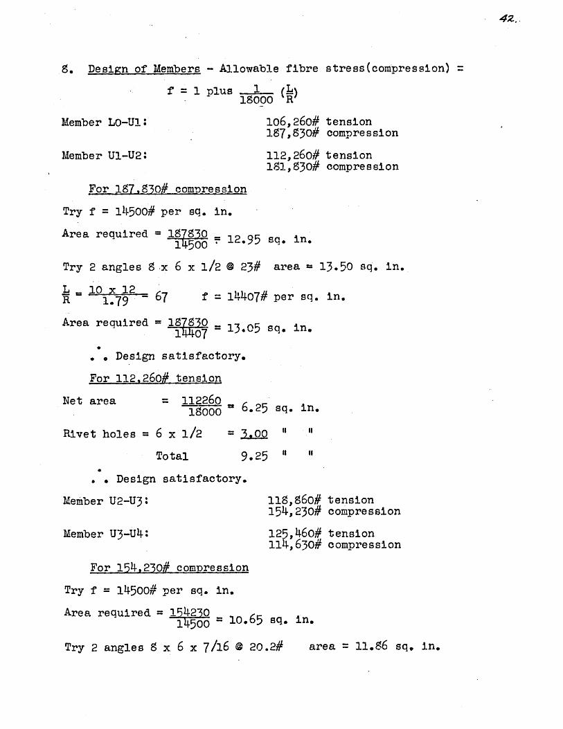
S. Design of Members - Allowable fibre stress(compression)
f'1 plus 1 (!!)18000 R
Member LO-UlI
Member U1-U2:
106,260# tension187,530# compression
112,260# tension181,930# compression
For 187,30# compression
Try f = 14500# per sq. in.
Area required = 1780 12.95 sq. in.
Try 2 angles 9 .x 6 x 1/2 @ 23# area = 13.50 sq. in.
L 10 x 12R 1.79 -67 f = 14407# per sq. in.
Area required = 180 = 13.05 sq. in.
Design satisfactory.
For 112,260# tension
Net area = 112260 6.25 sq. in.18000
Rivet holes = 6 x 1/2
Total
= 00
9.25 "
* . Design satisfactory.
Member U2-U3:
Member U3-U4:
118,860# tension154,230# compression
125,460# tension114,630# compression
For 154,230# compression
Try f = 14500# per sq. in.
Area required = 154230145T a = 71.65 sq. in.
Try 2 angles 8 x 6 x 7/16 @ 20.2# area = 11.86 sq. in.
"1
"

I~ 10 x12 = 66 .6R 1,00 . . f = 14450# per sq. in.
Area required - 14 100sq.n14,450 ~ 10.70 sq- in.
. Design satisfactory.
For 12;5460# tension.
Net area required = 12546018000 6.97 sq. in.
Rivet holes - 6 x 7/16 = 2.62 "
Total 9.59 "
Design satisfactory.
",
"I
Member U4-U5:
Member U5-U6:
135, 350#67,670#
110,710#103, 950#
tensioncompres sion
tensioncompression
For 135,350# tension.
Net area required = 135,35 71',000 = 7.53
Rivet holes = 6 x 1/2
Total
=- 3.00
10.53
Try 2 angles 8 x 6 x 7/16 @ 20.2# area = 11.6 sq. in.
For 103.950# compression
L = 13,3 x 12R 1.80 . . f = 12,500# per sq. in.
L = 26.6 x 12. 86R 3.73
Area required - 103950 _12500 - 8.35 sq. in.
. . Design satisfactory.
sq. in.
"I "
"t "

Member U6 - U7:
Member U7 - U8:
86,86o# tension128,100# compression
76,550# tension135, 410# compression
For 135,410# compression:
Try f = 13,500# per sq. in.
Area required = 135010.05 sq. in13500
Try 2 angles, 8 x 6 x 7/16 0 20.2# area - 11.86 sq. in.
L 11,8 x; 12.R 1.80 787 * . = 13392# per sq. in.
L - 23.6 x 12 =R 3,7 6.
Area required = 13541013392 *10.15 sq. in.
Design satisfa.ctory.
Design satisfactory for 96,860# tension.
Member U8 - U9;
Member U9 - U10:
49,100# tension127,660# compression
28,820# tension115,530# compression
For 127.660# compression:
Try f - 12000# per sq. in.
Area required = 127660 .12000 x1.6 sq. in.
Try 2 angles, 8 x 6 x 7/16 @ 20.2# area-- 11.86 sq. in.
L = 10.2 x 12R 1.80 71.3
L 21,4 x 12R 3.73
f = 14036# per sq. in.
68.8
Area required; = 12766o _14036 ~ 9-15 sq. in.
Design satisfactory.
44%.
4E6
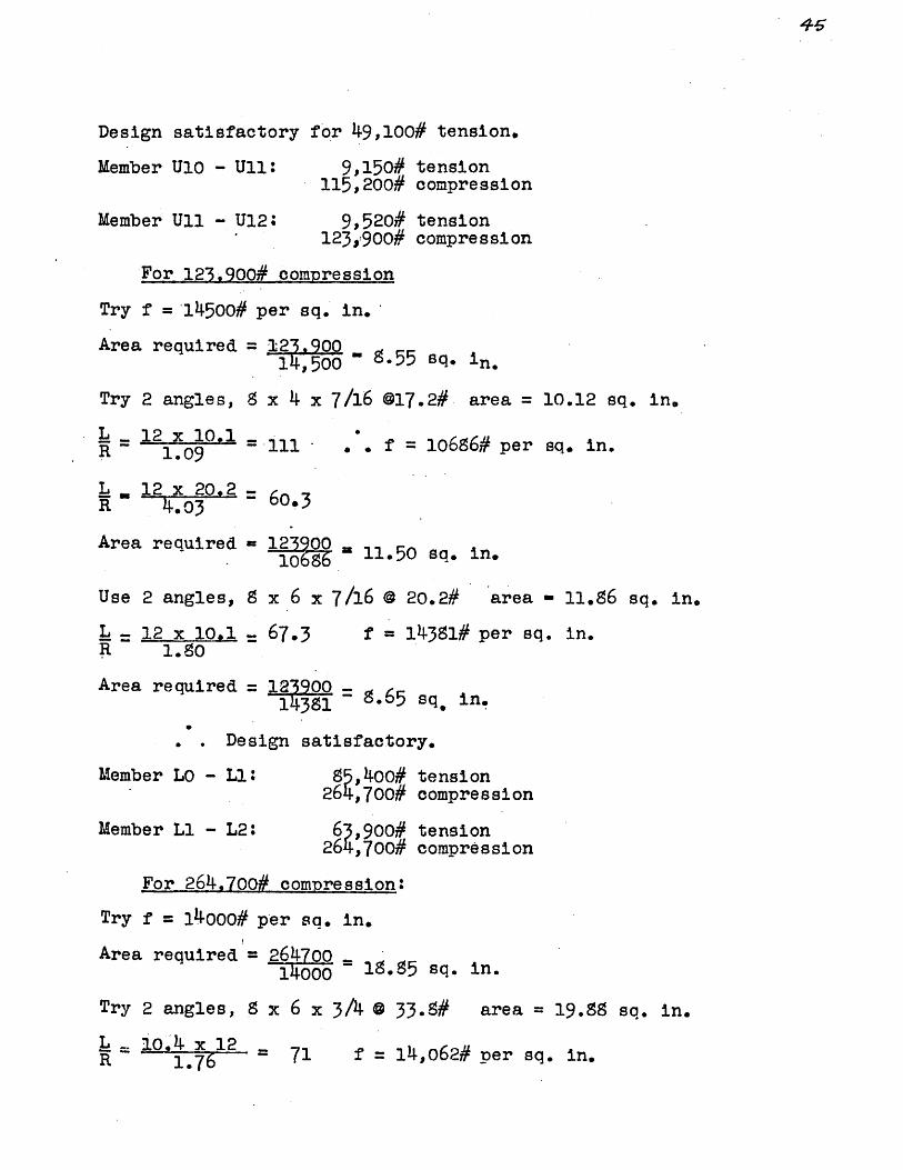
Design satisfactory for 49,100# tension.
Member U10 - Ull:
Member Ull - U12:
9,150# tension115,200# compression
9,520# tension123,900# compression
For 123.,900# compression
Try f = 14500# per sq. in.
Area required = 123.90014, 500 - 8.55 sq. in.
Try 2 angles, 8 x 4 x 7/16 @17.2# area = 10.12 sq. in.
L = 12 x 10.1 1 -R 1.09 . -. f = 1o6S6# per sq. in.
L .12 x 20,*2 -o.R 4.03 -6.3
Area required 123900 50 sq. in- 1686-115sqin
Use 2 angles, 8 x 6 x 7/16 @ 20.2#
L = 12 x 10.1 67.3R 1.80
area - 11.86 sq. in.
f = 14351# per sq. in.
Area required =123900 = .65 sq, in14381- .65sfa.tin.
.Design satisfactory.
Member LO - Li:
Member L1 - L2:
55,400# tension264,700# compression
63,900# tension264,700# compression
For 264,700# compression:
Try f = 140oo# per sq, in.
Area required = 264700 -14000 ~ 18.55 sq. in.
Try 2 angles, S x 6 x 3/4 0 33.9#
L=10. 1 x12 -
R 1.76--- 71 f 1l4,o6
area = 19.55 sq. in.
2# per sq. in.

Area required = 26470014-062 18*80 sq. in.
Design satisfactory.
Design satisfactory for 85,400# tension.
Member L2 - L3: 41,900# tension264,700# compression
For 264,700# compression:
Try f - ll,000# per sq. in.
Area required = 26470011000 = 24 sq. in.
Try 2 angles, 8 x 6 x 15/16 @ 41.7# area = 24.50 sq. in.
L s156 2 12R 1.74 - 107 f = 1102
Area required - 26470011002 = 24 sq. in.
Design satisfactory.
Member L3 - L4: 6o,650# tension237,700# compression
For 237,700# comoression:
Try f = 12000# per sq. in.
Area required = 23770012000 19* sq* in.
Try 2 angles 8 x 6 x 3/4 @ 33.S#
L =3.5 2 = 93.R 1.76 =9*
area = 19.55 sq. in.
f= 12124# per sq. in.
Area required = 237 02= 19.55 sq. in.12121.
Design satsifactory*

Member L4-L5:
Member L5-L6:
92,900# tension178,550# compression
100,600# tension163,500# compression
For 178,550# compression
Try f = 13000# per sq. in.
Area required -178550 -13000 - 13.70 sq. In.
Try 2 angles 8 x 6 x 9/16 @ 25.7#
L = 12,3 x 12 = 93R 1.78
area = 15.12 sq. in.
f = 13019# per sq. in.
L - 24.6 x 12 7R'~ 3.76 -78.5
Area required= 17855013018 = 13.70 sq. in.
Design satisfactory.
Member L6-L7:
Member L7-L8:
74,660# tension135,190# compression
75,520# tension113,930# compression
For 135,190# compression:
Try f = 14000# per sq. in.
Area required = 135190= 9.65 sq. in1400 =965s. n
Try 2 angles 6 x 6 x 1/2 @ 19.6#
L 10, 95 x 12R 1.87 70
L 21.70 x 122.67 97*5
area = 11.50 sq. in.
f = 11779# per sq. in.
Area required = 1~35190211779' a 11.50 sq. in.
Design satisfactory.
Design satisfactory for 75,520# tension.
47.

46.
Member L8 - L9: 62,750# tension97,550# compression
Member L9 - L10: 65,150# tension57,550# compression
For 87,550# compression:
Try f = 12500# per sq. in.
Area required - 8755012500 ~ 7.00 sq- in.
Try 2 angles, 6 x 6 x 3/S @ 14.9# area 5.72 sq. in.
L 10.1 x 12 .R 1 41.88 65
= 20.2Z 12 =91. f w 12328# per sq. in.
Area required -. 77.08 sq. in.
Design satisfactory.
Design satisf'actory for 65,150# tension.
Member Ul - L1: 12,000# compression
Member U2 - L1 21,900# tension
Member U2 - L2: 19,000# compiession
Member U3 - L2: 23,400# tension
Member U3 - L3: 26,900# compression
Use 2 angles, 4 x 4 x 5/16 @ 8.2#. area = 4.8o sq. in.
Design satisfactory.
'Member U4 - L3: 64,050# tension114,750# compression
For 114,750# compression:
Try f w 14000# per sq* in.
Area required - 114750 8.20 sq In1400 -o 20s. n

Try 2 angles, 6 x 6 x 3/9 @ 14.9#
L = 11.2 x 12 715~ 1.88 = 7
area = 9.72 sq. in.
f = 14019# per sq. in.
Area required = 1470 = 8.20 sq. in.
Design satisfactory.
Member U5 - L3: 1,450# tension51,300# compression
For 51.300# comoression
Try f w 11000#
Area required = 51300 4.66 sq. in.11000
Try 2 angles, 6 x 4 x 3/8 0 12.3# area = 7.22 sq. in.
L 13.75 x 12R = 1.50 - 110.5 f = 10725# per sq. in.
Area required 51300 4.78 sq. in.10725 De ig sa i f c o y
Design satisfactory*
Member U5 - L4: 40,290# tension1,190# compression
For 40.290# tension:
Net area required 40290 = 2.24 sq. in.18000
Rivet holes = 6 x 3/8
Total
= 225
4.49
"I
"I
Use 2 angles, 4 x 4 x 5/16 @ .2# area = 4,80 sq. in.
which: is aatisfactory for compression.
Member U6 - L4: 240# tension71,950# compression
447

For 71,950# compression:
Try f = 12,000# per sq. in.
Area required - 71950 = 6.oo sq. in.12000
Try 2 angles, 5 x 3-1/2 x 3/8 0 10.4# area - 6.10 sq. in.
L = 13.21 x 12 - 105R 1.51 f - 11163# per sq. in.
Area required - 6.47 sq. in.Design unsatisfactory.
Try 2 angles 5 x 3-1/2 x 7/16 a 12.o# area = 7.06 sq. in.Area required = 719s50
11163 = 6.47 sq. in.
Design satisfactory.
Member U6 - L5: 36,390# tension1,300# compression
For 36,390# tension:
Net area required = 3639018000 = 2.02 sq. in.
Rivet holes = 6 x 5/16 = 1.SS "
Total 3.90 "
",
"I
Use 2 angles, 4 x 4 x 5/16 e 9.2# area 4.8o sq.-in.
S 1*274 = 112
Design satisfactory.
Member U7 - L59* 1,500# tension41,o8o# compression
For 41,080# compression:
Try f - 12000# per sq. in.
Area req'd - 4120012000 = 3.43 sq. in.
Try 2 angles, 5 x 3-1/2 x 5/16 @ 9.7# area = 5.12 sq. in.

L = 12,31 x 12 = 99R 1.50 f = 11654# per sq. in.
Area required = = 3.52 sq. in.
Design satisfactory.
Member U7 - L6: 37,860#1,470#
tensioncompression
For 37.860# tension
Net area required = 37860 = 2.10 sq.18000=2.0s. in.
Rivet holes = 6 x 5/16
Total
SI i"
3.98 " "1
Use 2 angles, 4 x 4 x 5/16 @ 8.2#
L Ds1125 x 12 sttatqR - 1.24 10.
Design satisfactory.
Member U8 - L6
area = 4.9o sq. in.
18,790# tension59,540# compression
For 59540# compression:
Try f = 13000# per sq. in.
Area required -.504O
13000 1 5/ sq. in.Try 2 angles, 5 x 3-1/2 x 5/16 @ 9-7# area -5.12 sq. in.
L = 11,428 x 12 = 91.7R 1.50 f - 12303# per sq. in.
Area required = 49 = 4.2 sq. in.
Member U8 - L7: 32,350# tension20,180# compression
6/

For 32,380# tension:
Net area required = 28018000 "1.79 sq. in.
Rivet holes = 6 x 5/16
Total 3.67 "
Use 2 angles, '4 x 4 x 5/16 a 8.2#
L = 12 3 12 11R 1.117
area = 4.8 sq. in.
f = 10,300# per sq. in.
Area required = 20180(comp.) 10300 = 1.96 sq. in.
Design satisfactory.
17,720# tension32,950# compression
For 32,950# compression:
Try f = 10,000# per sq. in.
Area required 3.29 sq. in.
Try 2 angles, 3-1/2 x 3 x 5/16 @6.6#
L = 10.892 x 12 =R 1.10 =19
area - 3.86 sq. in.
f = 10074# per sq. in.
Area required = 90 3jo74= 3.29 sq. in. . . Design satisfactory.
Member U9 - Us: 35,040# tension24,550# compression
For 35,040# tension:
Net area required = 35040 = 1.94 sq. in.18000
Rivet holes = 6 x 5/16
Total 3.81 "
H
"
Use 2 angles, 3-1/2 x 3 x 5/16 @ 6.6#
L 11,9 -1.2 130 (too high)
area = 3.86 sq.in.
"
".
Member U9 - U7:

53.
Try 2 angles 4 x 3-1/2 x 5/16 @ 7.7# area = 4.50 sq. in.
_L = 11, 95 xZ 12 =31R 1.26
Design satisfactory.
Member U10 - L8: S,390# tension,960# compression
For 44,960# compression:
Try f = 12000# per sq. in.
Area required = 4496012000 3.74 sq. in.
Try 2 angles, 4 x 3-1/2 x 5/16 @ 7.7# area = 4.50 sq. in.
L 10357 x1g 98.8R lo 268,
Area required = 44960 4.26 sq.11671
. f = 11671
in.
For 35,390# tension:
Net area required = 3539Q = 1.9718000
Rivet holes = 6 x 5/10
Total
- 1.87
3.84
sq.
"
"
Design satisfactory.
Member U10 - L91 39,970# tsnsion37,870# compression
For 37.970# compression:
Try f - 11000# per sq. in.
Area required = 37s70q in11000
Try 2 angles, 5 x 3-1/2 x 5/16 @ 8.7# area - 5.12 sq. in.
= 13.4 1- = 100 f = 11571# per sq. in.
Area required = 37870 327 sq in.11571 =32 q n
design satisfactory.
in.
",
"I

Member Ull - L90" 29,180# tension30,940# compression
For 30,940# compression:
Try f - 11500# per sq. in.
Area required = 300 = 2.68 sq. in.11500
Try 2 angles, 4 x 3-1/2 x 5/16 @ 7.7# area = 4.50.sq. in.
. 1.7 x12 -97.
Area required = 30940 262 sq11779
f = 11779# per sq. in.
in.
For 29.180# tension:
Net area required = 29190 a 1.6211779
Rivet holes = 6 x 5/16
Total
"
3.4.9 "
Design satisfactory.
Member 111 - L10: 37,50#42,070#
Fbr 42,070# compression:
Try f = 11500# per sq. in.
Area required - 42070 - 3.66 sq. in.
Try 2 angles, 5 x 3 x 5/16 @ 8.2#
L = 13*3 12 =.599.5R 1.61
tensioncompression
area = 4.8o sq. in.
T = 11613
Area required = 4207011613 " 3*62 sq. in.
For 37.680# tension:
Net area required = 37680 - 209 sq in.
Rivet holes = 6 x 5/16 -- I._ " "
sq. in.
i
I- 1.87
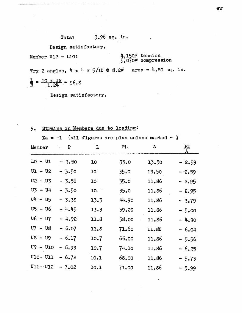
Total 3.96 sq. in.
Design satisfactory.
Member U12 - Llo: 4,150# tension5,070# compression
Try 2 angles, 4 x 4 x 5/16 0 S.2# area - 4.9o sq. in.
L 10 xt 12,= 96.5
Design .satisfactory.
9. Strains in Members due to loading
Xa = -1 (all figures are
Member P L
plus unless marked -
PL A
LO - U1 -3.50
U1 - U2 -3.50
U2 -. U3 -3.50
U3 - U4 - 3.50
U4 - U5 - 3.39
U5 - U6 - 4.45
U6 - U7
U7 - US
- 4.92
- 6.07
U8 - U9 - 6.17
U9 -U10
U10- Uli
U11-- U12
- 6.93
- 6.72
- 7.02
10
10
10
10.
13*3
13.3
11.8
11.8
10.7
10.7
10.1
35.0
35.0
35.0
35.0
59.20
58.00
71.6o
66.oo
13.50
13.50
11.86
68.oo
10.1 71.00
- 2.59
- 2.59
- 2.95
- 2.95
- 3.79
- 5.00
- 4.90
- 6.o4
- 5.56
- 6.25
- 5.7311.86 - 5.99
PLA

Membe P L L A A
LO -
L1 -
L2 -
L3 -
L4 -
L5 -
L6 -
L7 -
L9 -
U1 -
U2 -
U2 -
U3 -
U3 -
U4 -
U5 -
U5 -
U6 -
U6 -
U7 -
U7 -
Us -
Ug -
Li
L2
L3
L4
L5
L6
L7
L8
L9
L10
Li
Li
L2
L2
L3
L3
L3
L4
L4
L5
L5
L6
L6
L7
3.64
3.64
3.,64
4.83
5.356.36
6.66
7.35
7.50
7.75
0
1o.4
10.4
15.6
13.65
12.3
12.3
10.85
10.85
10.1
10.1
37.9
37.9
56.70
66.oo
65.90
78.40
72.50
79*0
75.80
78.30
0
0
0
0
2.84
- 1.07
.18
.96
1.10
1.05
.59
.79
11.2
13.75
10.9
13.21
11.7
12.319
11.25
11.429
12.3
31.60
14.70
9. 6o
2.38
11.20
13.50
12.15
6.76
9.73
19.88
19.58
24.50
19.88
15.12
15-12
10.12
10.12
8.72
8.72
4.80
4.80
4.80
4.50
4.8 o
8.72
7.22
4.50
7.o6
4. o
5.12
4.0
5.12
4.0
1*90
1.090
2.31
3*32
4.35
5.16
7.15
7.85
5.70
5.98
0
0
0
0
0
3.62
- 2.05
2.00
.37
2.34
- 2.64
2.53
1.32
2.02
Member B L PL A PL

Member P L PL A PLA
U9 - L7 - .74 10.892 8.12 3.86 - 2.10
U9 - L8 .85 11.95 10.10 3.86 2.63
U10- L8 1.35 10.357 14.oo 4.50 3.12
U10- L9 .36 13.4 4.83 5.12 .94
Ull- L9 - .25 10.173 2.54 4.50 - .56
Ul1-L1O ..33 13.3 4.4o 4.8o .92
U12-L10 1.75 10. 17.50 4.8o 3.65
Drawing #9 shows the Williot diagram drawn for these strains.
10. To draw influence line for Xa using areas we row have
instead of assuming S/A = 1. (Deflections from Drawing #9).
Joint Saa Vertical Vertical Horizontal Horz.def. 6 Xa def. Sam Xa
LO 6780 0 0 6780 1.
Ul 11.60 .0017 6110 .902
U2 23.20 .0034 5562 .821
U3 34.8o .0051 5057 .748U4 46.4o .oo67 46oo .678
U5 5410. .0795 W19 .617U6 963. .142 3838 .555U7 1355. .200 3626 .534U8 1690. .249 3466 .510U9 1965. .289 3386 .498
'L U UL6 U~3Ujf,, VV Ut i
Z-n/Xence. l e +'r ca-n/ vegtst-'on 47 L. a due. o
/17d nda/ /04.ds.
*3 L2.oci ? L/4. till

Nll
0 Ic.00:7
.o0
54
.0051
-0067
C'
.00
.007
CP-
.
03
C 1~ U,
.0017
.3(
6
7

Joint 8 aa
Ulo
Ull
U12
U13
U14
U15
u16
U17
U18
U19
U20
U21
U22
U23
L20
Note: See Figs. #14 and#15 for influence lines.
X. Consideration of Results;
After drawing the second influence line for the re-
dundant, we notice that is is almost exactly similar to the
first. For instance, due to the snow load over the entire
rodf in the first case, we find that from our first influence
line we get a horizontal reaction of 29580# and calculating
Verticalde f, em
2145.
2265.
2290.
2265
2145
1965
1690
1355
957
540
46.40
34.80
23.20
1, 6o
0
VerticalXa
.316
*334
.o338
. 334
.316
*289
.249
0200
.141
*0795
.0067
.0051
.0034
.0017
0
Horizontaldef. cm.
3346
3356
3390.
3420
3430
3400
3320
3160
3020
2620
2110
1710
1210
664
0
Horz.Xa
.494
.495
*500
.505
.506
.502
.490
*467
.445
*387
* 312
*252
*179
.098
0

46/
this horizontal reaction for the full snow by the second
influence line we get as follows
.oo67 x 4ooo = 27
.142 x 9200 1305
.249 x 15200 3780
.316 x 20000 6320
.335 x 10000 = 3380
14812x 2
29624#
This seems very close for the first attempt and so
as to check the work, "H" was then calculated for full snow,
the work for which is shown on a later page, by means of
algebraic summation, then it was found that the "H" obtained
by these means was 29,592#, which checks the "H" as found by
means of the Williot diagram. Therefore, it would seem as
if the first attempt is satisfactory, because it was assumed
equal to 29580# and it was found to be 29,592# by algebrAic
summation or 29,624# by using the Williot diagram for the
deflections, and using the designed areas. In a previous
first attempt an error was made in the drawing of the in-
fluence line which threw "H" out approx. 4%. The error was
not caught until the sections were designed and while it was
noticed that this difference in "H" made considerable differ-
ence in the individual stresses of the members, but that
when totals were taken and the members designed only a few

varied from this design and then only slightly.
It seems very strange that the influence line for
the redundant should be the same to all practical purposes
when drawn for 1 = and theft drawn considering A and L.A
I.have already checked my second infludnce line by means
of algebraic summation and found that it has checked-now I
can check my first influence line by algebraic summation
also by simply adding up the columns Sa and SaSo and divid-
ing the latter by the former. Doing this for the full snow
load, I find that my redundant comes to 29,410#, while the
value I found by the influence line, considering = 1, was
29,580#. This explains why I have come practically exact
on my first try, there evidently being a small error in my
first Williot diagram in the correct direction. On the other
hand, it also shows that for this truss, when we consider
A = 1, we come extremely near the truth when solving for our
redundant.
Professor Albert Haertlein, of the Dept. of Civil
Engineering, Harvard, and Lee S. Johnson, have made a study
of the difference in the following equations. They have con-
sidered several different structures in their comparison. An
article on their work appears in the Engineering News Record
for June, 1936. The equations are.
:g-;. - /FIE

CAC
66 U
The results of their investigation were that all
equations came very near the truth. In their investi-
gation they make no mention of assuming = 1, and IA
believe . = 1 is as good an assumption as any. I in-A
vestigated some arches worked out by Ketchum and Johnson
and found that sometimes q = 1 gave a better approx.A
while sometimes A = 1 gave a better assumption, and that
assuming 9 1 usually gave poorer results. For the
case of the arch I am showing by means of algebraic sum-
mation the difference between these different assumptions.

to snow all over by algebraic summation:
Bar
LO-Ul
U1-U2
U2-U3
U3-U4
U4-U5
U5-U6
u6-U7
U7-Us
US-U9
U9-U1O
Ulo-Ull
Ull-U12
Lo-L1
L1-L2
L2-L3
L3-L4
L4-L5
3
10
10
10
10
13.3
13.3
11.8
11.5
10.7
10.7
10.1
10.1
10.4
10.4
15.6.
13.65 19.5
12.3 15.12
12.3 15.12
A
13.50
13.50
11.56
11.86
11.56
11.86
11.56
11.86
11.6
11.56
11.56
11.86
19.85
19.5 5
24.50
.813 6.36 153.5L5./L6 4o.5
S/A
.740o
.74
.544
.544
1.12
1*12
1.00
1. 00
.902
.902
.os45
.545
.525
.525
*636
.688
.513
Sa
- 3.50
- 3.50
- 3.50
- 3.50
- 3.38
- 4.45
- 4.92
- 6.07
- 6.17
- 6.93
- 6.77
- 7.02
3.64
3.64
3.64
4.3
5.35
0'.
9. To find Xa due
So
- 55.4
- 5.4
- 58.4
- 58.4
- 52.60
-109.5
-147.5
-206.
-225.5
-265.o
-267.5
.- 292.0
0
0
0
54.o
101.2..
Sa'
12.2
12.2
12.2
12.2
11.14
19.8
24.2
36.9
38.0
48.o
45.8
49.2
13.3
13.3
13.3
23.3
28.6
Sa. So
204.0
204.0
204.0
204.0
17.0
486.0
725.
1250.
1391.
1857.
1911;
1980.
0
0
0
261.0
541.o
978.0
Sa- S/A
9.00
9.0
10.3
10.3
12.
22.2
24.2
36.
34.3
43.3
35.7
41.6
7.0
7.0
5.5
16.1
23.2
10.
44o.
795.
SaSos /A
154.o
154.o
172.00
172.0
199.0
545.0
7250o
1250.
1254.
1675.
1530.
1673.
33.0

Bar
L6-L7
L7-L8
L8-L9
L9-L1O
Ul-Li
U2-L1
U2-L2
U3-L2
U3--L3
U4-L3
U5-L3
U5-L4
U6-L4
u6-L5
U7-L5
U7-L6
US-L6
US-L7
U9-L7
8.72
7.22
4. o
7.o6
4. 0
5.12
4.50
5.12
4.8o
3.86
1.255
1.90
2.27
2.17
2-44
2.40
2.35
2.24
1.87
2.51
s
10.5
10.85
10.1
10*1
-0
0
0
0
1A SA
10.12 1.07
10.12 1.07
8.72 1.16
8.72 1.16
Sa
6.66
7.35
7.50
7.750
2. - 44.0411.2
13.75
10.9
13.21
11.7
12. 319
11.25
11.428
12.30
10.892
-1.07
.88
- .18
-96
-1.10
108
.59
.79
.74
- 56.3
46.7
- 41.16
49.9
-56.34
55.5
- 10.97
44.4
- 41.13
1.15
.77
.03
.92
1*21
1.17
.35
.62
.55
- 128.0
6o.3
41.1
7.4
47.5
62.*0
6o.o
- 6.5
35.0
32.6
2.2
1.*
0.1
2.2
2.9
2.7
0.9
1.2
1.5
- 164.5
114.5
93.5
16.0
117.0
149.0
141.0
- 14.6
65.5
91.o6
5))
So
189.5
228.5
253.0
267.0
0
0
0
0
0
Sa
44.3
54.0
56.0
6o.0
0
0
Sa. So
1265.0
1680.o
1900.0
2070.0
0
aS /A
47.4-
57. 9
65.0
69.6
0
0
0
0
0
0
0
.SaSos /A
1355.0
1800 * 0
2204.0
2400.0

Bar 8
U9-L8 11.95
Ulo-L8 10.357
U10-L9 13.4
Ull-L9 -10.173
Uil-LlO 13.3
U12-Llo 10.
Sa
So
Sa -
SaSo -
Sa''S/A -
SaSoS/A-
261.35
7057.62
1375.67
39078.68
1326.40
39251.00
Note: All figures are plus unless marked - .
A S/A
3.86
4.5o
5.12
4.50
4. 8o
4.50o
3 .10
2.30
2.62
2.26
2.77
2.08
SaS/A-Sa
.85
1.35
.36
-. 25
.33
1.75
Totals:
So
47.60
27.87
19.20
- 14.59
19.40
49.80g
Sa'
.72
1.82
.13
.o6
.11
3.05
Sa. So
40.5
37.6
6.9
3.64
6.4
87.2
2.2
4.2
0.3
0.1
0.3
6.4
SaSos/A
125,O
86.5
18.1
8.2
17.7.
181.0

*. Summ
Member
LO-U1l
U1-U2
U2-U3
U3-U4
U4-U5
U5-U6
U6-U7
U7-U8
US-U9
U9-U1O
Ulo-Ull
U11-U12
LO-L1
L1-L2
L2-L3
L3-L4
L4-L5
L5-L6
L6-L7
L7-L8
L8-L9
L9rL1o
ations of Sa-S and SaSoS.
S
10
10
10
10
13.3
13.3
11. 0
11.8
10.7
10.7
10.1 1
10.1
10.4
10.4
15.6
13.65
12.3
12.3
10.85
101685
10.1
10.1
Sa
12.20
12.20
12.20
12.20
11.4A
19-8
24.2
36.5
3.0
48.0
45.8
49 . 2
13.3
13.3
13.3
23*3
28.6
410.5
44.3
54.0
56.0
6o.o
SaSo
204.0
204.0
204.0
2041.0
178.0
486.0
725.0
1250.0
1391.0
1857.0
1811.0
1980.0
0
0
0
261.0
541.0o
978.0
1265.0
1680.o
1900.0
2070.0
Sa S
122.0
122.0
122.0
122.0
152.0
264.0
286.0
434.0
407.0
513.0
462.0
497.0
13. 8 *
138.5
207.5
318.0
352.0
498.0o
480.0
585.0
566.o
607.0
SaSoS
1220.0
1220.0
1220.0
1220.0
2370..0
3520.0
8550.0
14750.0
14900.0
19950.0
18300.0
20000.0
0
0
0
3560.0
6650.0
12000.0
13700.0
18200.0
19200.0
20900.0

M nSemu er
Ul-L1
U2-L1
U2-L2
U3-L2
U3-L3
U4-L3
U5-L3
U5-L4
u6-L4
U6-L5
U7-L5
U7-L6
US-L6
U8-L7
U9-L7
U9-L8
U10-L8
U10-L9
U1l-L9
U11-L1O
U12-LlO
Sa'.ao
0
0
0
0
11.2
13.75
10.9
13.21
11.7
12.319
11.25
11.428
12.30
10.892
11.95
10.357
130 4
10.173
13.3
10.
0
8.1
1.15
.77
.03
.92
1.21
1.17
.35
.62
.55
.72
1.82
.13
.o6
.11
3.05
0
0
0
0
0-128.0
6o.3
41.1
7.4
47.8
62.0
6o. o6.,
35.0
32.6
40.5
37.6
6.9
3.64
6.4
87.2
Totals: Sas
SaSoS
- 15,216.10
- 411,220.20
Note: All figures are plus unless marked - .
SSaSoS
90.68
15.8
8.4
*4.
10-7
14.9
13*2
4.0
7.6
6.o
8.6
18.9
1.7-
.6
1.3
30.5
-1432.0
830.0
448*0
97.8
560.0
765.0
676.0
- 74.4
431.0
355.0
484.c
389.0
92.5
37.0
85.2
872.0

69.
4. Comparison of Approximations
-, - = =- QC- 43 v'V-e- C-I-
.. 1 ., --N441-477-1-tO =
XZ#£1
-z C,
= zzIW
From the above, it would appear at least for this case,
the approximation S/A = 1 is better than either of the other
two. In the summation So and Sa, the signs were taken as
they were in SaSo and Sa , otherwise the result would be
incorrect, because if we assume a quantity equal to unity
we still keep the same sign.
CO,
'S -1. (6 2- 0 0 %C.
-z- 6 1

To
XI. Calculation of Actual Weight of Truss:
Member
Lo-U1
U1-U2
U2-U3
U3-U4
U4-U5
U5-U6
U6-U7
U7-U8
U8-U9
U9-U10
UlO-Ull
Ul1-U12
LO-L1
L1-L2
L2-L3
L3-L4
L4-L5
L5-L6
L6-L7
L7-LS
L8-L9
L9-Llo
2 angle s
2 "
2 "
2 '
2
2
2 "
2
2
2 "
2 "
2 "
2
2 "
2
2
2 "
2
2 "
2 "
2 "
scription
2 " 6 x 6 x 3/8 @ 14.9# x lo.1' 301
De
8
6
6
6
8
S
S
S
S
S
8
5
8
8
S
5
6
x 6 x 1/2 @ 23# x 10'
x 6 x 1/2 @ 23# x 10'
x 6 x 7/16 @ 20.2# x 10'
x 6 x 7/16 0 20.2# x 10'
x 6 x 7/16 @ 20.2# x 13.3'
x 6 x 7/16 @ 20.2# x 13.3'
x 6 x 7/16 @ 20.2# x 11.8'
x 6 x 7/16 @ 20.2# x 11.5'
x 6 x 7/16 @20.2# x 10.7'
x 6 x 7/16 @ 20.2# x 10.7'
x 6 x 7/16 @ 20.2# x 10.1'
x 6 x 7/16 @ 20.2# x 10.1'
x 6 x 3/4 @ 33.9# x 10.4'
x 6 x 3/4 @ 33.9# x 10.4'
x 6 x 15/16 @ 41.7# x 15.6'
x 6 x 3/4 @ 33.8# x 13.65'
x 6 x 9/16 @ 25.7# x 12.3'
x 6 x 9/16 @ 25.7# x 12.3'
x 6 x 7/16 @ 17.2# x 10.85'
x 6 x 7/16 @ 17.2# x 10.85'
x 6 x 3/ @ 14.9# x 10.1'
Weight
46o
46o
404
404
54o
540
476
476
432
432
405
4o
704
7o4
1300
925
633
633
373
373
301

De scrit~tion
2 angles 4 x 4 x 5/16 @ 8.2# x 2.86'
2 " 4 x 4 x 5/6 @ .2# x 10. 4'
2 " 4 x 4 x 5/16 @ S.2# x 5.7'
Weight
47
171
94
Ul-Li
U2-Li
U2-L2
U3-L2
U3-L3
u4-L3
U5-L3
U5-L4
U6-L4
u6-L5
U7-L5
U7-L6
U8-L6
U8-L7
U9-L7
U9-L9
Ui0-L8
Ulo-L9
Uli-L9
Uil-L10
U12-L10
2
29
39
79
74
92
14
85
.9
02
" 3-1/2 x 3 x 5/16 @ 6.6# x 10.9'
2 " 4 x 3-1/2 x 5/16 @ 7.7# x 11.95'154
2 " 4 x 3-1/2 x 5/16 @ 7.7# x 10.36'159
2 " 5 x 3-1/2 x 5/16 @ 8.7# x 13.4.'2
2 4 x 3-1/2 x 5/16 @ 7.7# x 10.17'
2 " 5 x 3 x 5/16 @ 8.2#-x 13.3'
2 " 4 x 4 x 5/16 @ 8.2# x 10'
33
156
218
16415742#
231484
Member
7/.,,
2 " 4 x 4 x 5/16 @8. 2# x 11.5'; 1
2 "4 x 4 x 5/16 @ 8.2# x 11.2' i
2 " 6 x 6 x 3/8 @"14.7# x 11.2' 3
2 " 6 x 4 x 3/8 @ 12.3#-x 13.75' 3
2 " 4 x 4 x5/16 @ S.2# x 10.9' 1
2 5 x 3-1/2 x 3/8 @ 10.4# x 13.21'2
2 " 4 x 4 x 5/16 @ 8.2# x 11.7' 1
2 5. x 3/1/2 x 5/16 @ S.2# x 12.31'2
2 " 4 x 4 x 5/16 @ 8.2# x 11.25' 1
2 " 5 x 3 x 5/16 @ s.7# x 11.43' 1
2 " 4 x 4 x 5/16 @ 8.2# x 12.3' 2
Member Des riD tion

Details 30%
Total
31484#164
31320#
40720
This comes close enough to the assumed weight of
4Sooo# so that another stress analysis is not neces-
sary.
72

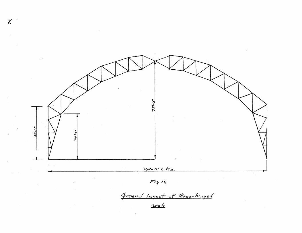
DESIGN OF THREE-HINGED ARCH
XII. General
The dimensions of the three-hinged arch have been
kept as near as possible the same as those for the two-
hinged arch. The only changes being made are those that are
required to change the two-hinged arch into a three-hinged
arch. For the layout see Fig. #16. The same sections will
be used for the bracing and girts, but of course the detailE
would vary somewhat. Fig. #17 shows a plan view of the brac-
ing system.
XIII. Loads
The loading will be the same as in the case of the
two-hinged arch with the exception that the loads will come
into the truss a little different than in the former case,
near the centre pin due to the different arrangement of the
purlins at this section. The dead weight of the truss will
be assumed as 48,000# and will be distributed at the panel
points as snown in Drawing #11 in combination with the roof
loads. The panel loads up to and including panel point #U10
will be the same as in the previous truss. The following
are the panel loads for panel points U10 and Ull.
Dead Load:
At Ulo:
7-35 (10.7 plus 5.0) 40 =4615#
purlin 00#
Total S115#
P11
07C 7/7

U(.
F'C7 -#f7
/L a4Z-eo- ./ b 4rA.<.-m1-7 -- At,-te. J .4L P-Ce

At Ull:
7.35 (5 plus 10.1) 40 = 4439#
purlin = 3500#
total 7939#
Snow Load:
At Ul0
Snow 25# per sq. ft. horizontal projection.
Load - 25 x 40 x 15 = 15000#
At Ul:
Load = 25 x 40 x 15 = 15000#
Wind Load:
At Ulo:
Horizontal = 2720 plus 170 = 2890#
Vertical = 7300 plus 1390 = 8690#
At Ull:
Horizontal - 170 plus 340 = 510#
Vertical = 1390 plus 2780 =4170#
Note: Drawings #12 and. #13 and #14 show respectively the
loadings for snow all over, snow right, wind right.
XIV. Stress Analysis for the various loadings:
l. General.
The three-hinged arch is statically determined and
the horizontal reactions may be found by taking moments about
the centre hinge,

2. Dead Load.
The stress analysis for dead load is shown on
Drawing #11.
Calculation of Horizontal Reaction.
Moments about Hinge
H x 75 - 82.57 x SO plus (10.54 x 10) plus(lo.71 x 20)
plus(2.6 x 30) plus(9.15 x 40) plus(2.60 x 50) plus
(2967 x 9o) plus(13.35 x 60) plus(2.6o x 70) = 0
H = (plus) 31.51 kips
The horizontal components of the striess in the
top chord were now found by taking moments and the stres-
ses in the remainder of the members were found by writ-
ing V = 0 and H = 0 for each joint. This procedure has
been followed in all the stress analysis. It was found
that in calculating the horizontal components in the top
chord that it was not good enough to use the slide rule
as the error resulting was sometimes of considerable mag-
nitude.
3. Snow Load all over.
The stress analysis for snow all over is shown
in. Drawing #12.
Calculation of horizontal reaction
H x 75 - (54.4 x So) plus (9i2 x 60) plus(15.20 x 40)
plus (15.00 x 20) plus (15.00 x 10) = 0
. . H = (plus) 36.56 kips

76.
4., Snow Right. - Stress analysis for snow right is shown
in Drawing #13.
Calculation of left vertical - moments about
right reaction.
v x 16o =(15 x 70) plus(15 x 60) plus(15.20 x 40)plus(9.20 x 20)
V = 17.14 kips
V - 58.40 - 17.14 = 41.26 kips
Calculation of horisontal reaction--moments
about centre nin
H x 75 17.14 x 800
. . H 18.28 kips
5. Wind Right,
Stress analysis for wind right is shown in Drawing
#14.
Calculation of left vertical reaction
V x 160 (4.17 x 70) plus (8.69 x 60) plus (17.05 x 40)
plus(20.65 x 20) plus(12 x 10) plus(12 x 20)
.plus(12 x 30) plus(15.65 x 40) plus(15.75 x 57.50)
plus(8.92 x 70) plus(2.89 x 77.5) plus(.510 x 78.5)
. . V = (plus) 31.51 kips
V = 61.46 - 31.51 = 29.95 kips
Calculation of left horizontal reaction
H x 75 31.51 x 800
9*. H 33.61 kips
H = 79.62 - 33.61 = 46.01 kips

XV. Calculation of Maicimum Stresses:
Member SnowRight
LO-Ul
U1-U2
U2-U3
U3-U4
u4-U5
U5-U6
U6-U7
U7-US
US-U9
U9-UiO
U1o-Ull
U11-LlO
LO-LI
L1-L2
L2-L3
L3-L4
L4-L5
L5-L6
LeftDead Wind
Right
27.72
33,72
4o.32
46.92
55.50
36.75
21.15
10.60
- 1.36
-10.70
-17.60
-18.65
-114.9o
-114.so
-114.9 o
-100.00
- 72.60
- 60.30
LeftSnow all
over
69.56
69.56
69.56
69.56
71.20
53.40
32.60
15.35
.6o
-14.15
-23.15
-24.70
-133.00
-133.00
-133.00
-123.00
- 94.30
- 79.00
46.84
46.84
46.4
46.84
45.30
47.oo
40.o80
39.80
28.70
20.70
5.36
5.67
-66.6o
-66.6o
-66.60
-71.50
-66.oo
-65.o00
22.72
22.72
22.72
22.72
25.s0
6.48
- 8.20
-24.35
-28.10
-34.0
-28.60
-30.40
-66.6o
-66.6o
-66. 6o
-51.50
-28.45
-13.95
86.12
86.12
86.12
86.12
83.30
86.50
75010
73.20
52. 0
37-0o
9.85
1o.40
-122.30
-122.30
-122.30
-131.50
-121.20
-119.50
-190.98
-190.98
-169.98
-136.98
-129.20
-148.20
-145.50
-139.25
-111.00
- 84.40
- 52.20
-'55.80
167.50
140.03
119.03
125.00
130.50
124.oo
Maximum(plus.)
136.56
142.56
149.36
155.76
164.60
129.73
96.25
83.80
51.44
27.10
- - -
52.70
25.23
4.23
25.00
57,90
63070
Maximum(minus)
163.26
157.26
129.66
90.06
73.70
111.45
124.35
128.65
112.36
95.10
69.8o
74045
303.70
303.70
303.70
283.00
222.25
193.75

Snow allovr.
L6-L7
L7-L8
L8-L9
L9-LlO
Ul-L1
U2-L1
U2-L2
U3-L2
U3-L3
U4-L3
U5-L3
U5-L4
U6-L4
U6-L5
U7-L5
U7-L6
U8-L6
Ug-L7
Snow,Rigoht
- 43.90
- 32.0
- 21.70
- 16.6o
0
0
0
0
0
- 46.70
- 21.32
15.43
- 32.20
11-35
- 12.80
10.05
- 22.56
12.60
- 54.00
- 40.30
- 23.50
15.95
0
0
0
0
0
6o.oo
- 17.53
14.147
- 34.7514.70
- 16.64
16.37
- 32.09
15. 4o
a
0
0
- 38.10
1*68
- 1.37
- 96.7-89
- 1.02
-99
- 15.93
8.48
Lef't
- 56.50
- 48.90
- 37.90
- 27.85
0
0
0
0
0
-21.s0
-19.21
15.85
-24.99
13.80
-15.63
15.35
-16.17
6.93
WindRigrht
2.54
8.65
14.30
11,86
0
0
Member
-103.50
- 90.00
- 69.60
- 51.40
0
0
0
0
0
- 70.30
3.08
- 2.53
- 17.0
1;64
- 2.01
1.1
- 29.26
15.55
Dead
0
Lef~t
105.00
79.70
49.10
22.00
-12.00
21*90
-18.00
23.00
-26.90
91.50
-19.14
15.80
2.90
- 5.14
5.86
- 5.80
34.42
-28.25
Maximum(pius)
61,.10
46.90
27.140
5.40
21.90
23.00
44.8o
31.28
26.79
- - 0-
27.21
11-86
35.08
Maximum(minus)
TP-rt. Right L f
18.00
26.90
138.40
140.53
74.99
30.44
- -m -
67.99
15.65
(0
147.4o
122.80
91.30
68.oo
12.00

Member Dead Snow all Snow Wind Maximum Maximumover Right Left Right Left (plus) (minus)
U9-L7 - 11.71 14.29 7.85 - 6.43 - 14.47 25.75 14.04 32.61
U9-L8 10.50 16.50 9.09 7.40 16.70 -29.70 34.60 19.20
Ul0-L - 15.70 21.70 -18.99 - 2.73 - 34.8 41.24 25.54 53.31
Ulo-L9 9.90 13.20 18.70 - 5.47 34.30 -40.30 44.20 30.40
U11-L9 - 1.82 3.47 - 2.64 - .72 - 4. 21.86 20.04 7.42
Note: All signs are plus unless marked

8z
XVI. Design of Members:
Member LO-Ul:
Member U1-U2t
136,560# tension163,26o# compression
142,56o# tension157,260# compression
For 163,260# compression;
Try 'f = 14,000# per sq. in.
Area required - 16326014ooo 170 sq. In.
Try 2 angles 8 x 6 x 7/16 @ 20.2#
L 10 x 12R 1.0 '5
area = 11.86 sq. in.
. . f = 14450# per sq. in,
Area required = 16326014450 = 11.30 sq. in.
Design satisfactory.
-For 142,560# tension:
Net area required = 14256018000 = 7*93 sq. in.
Rivet holes = 6 x 7/16Total
= 2,63 "
10.56 "
Design satisfactory
Member U2-U3:
Member U3-U4:
149,360# tension129,660# compression
155,760# tension90,060# compression
- For 155,760# tension:
Net area required = 155760 .65 sq. in18000
Rivet holes = 6 x 7/16
Total
= 2,63 "
11.28 "
Use 2 angles 8 x 6 x 7/16 0 20.2#
",
"I
area = 11.96 sq. in.
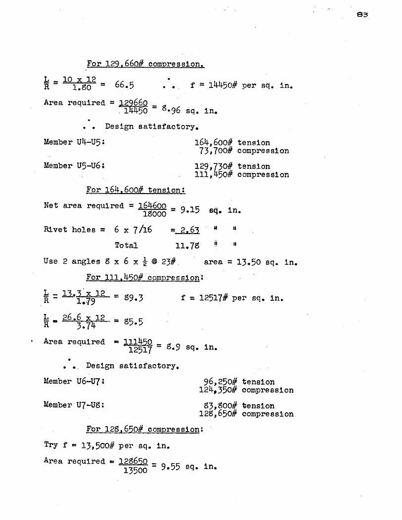
83
For 129,66o# compression.
L = 10 x 12R 1.80 = . * f = 14450# per sq. in.
Area required = 12966014450 ~ -96 sq. in.
Design satisfactory.
Member u4-U5:
Member U5-U6:
164,600# tension73,700# compression
129,730# tension111,450# compression
For 164,600# tension:
Net area required = 1646oo = 9.15 sq. in.19000 =91 4 n
Rivet holes = 6 x 7/16
Total 11.75 i-",
Use 2 angles 8 x 6 x @23#.
For 111.-,45o# compressionI
area = 13.50 sq. in.
L - 13. 12 = 89.3R ~1.79 9, f = 12517# per sq. in,
L . 26.6 x 12 = 55R - 3.74 8*5
Area required 111450 812517 ~.9 sq. in.
. .Design satisfactory.
Member U6-U7;
Member U7-U8:
96,250#124,350#
83,800#128,650#
tensioncompression
tensioncompression
For 128,650# compression:
Try f = 13,500# per sq. in.
Area required = 128650 955 sq. in.13500

Try 2 angles S x 6 x 7/16 @ 20.2#
L 11,91.X012 _ 7 7R 10
Area = 118.6 sq. in.
.. f = 13,392# per sq. in.
L 6 x 12 6R 3.73 7.*
Area required = 12565013392 ' 9.70 sq. in.
Design satisfactory.
Design satisfactory for 96,250# tension.
Member US-U9:
Member U9-U1O:
51,440# tension112,360# compression
27,100# tension95,100# compression
For 112,360# compression
Try f = 13,000# per sq. in.
Area required = 11236013000 - 8,66 sq. in.
Try 2 angles 9 x 4 x 7/16 @ 17.2#
R 10.1 12 =118R 1.09 -
area = 10.12 sq. in.
f = 10149# per sq. in.
L 21,4 12_= 63*8R 4*.03
Area required = 112360 1110 sq in10149 '1sqin
Use 2 angles 9 x 4 x 1/2 0 19.6# area = 11.50 sq. in.
. Design satisfactory.
Design satisfactory for 51,440# tension.
Member Ulo-Ull:
Member Ul1-L10
For 74,450# compression:
Try 2 angles 8 x 4 x 7/16 @ 17.2#
69,oo# compression
74,450# compression
area = 10.12 sq. in.
8+

L= 12 x 0.7 = 1R 1.09 f - 10144# per sq. in.
Area required = 74450101D4 7*37 sq. in.
Design satisfactory.
Member LO-L1:
Member L1-L2:
52,700# tension303,700# compression
25,230# tension303,700# compression
For 303,700# compression;
Try f = 14,000# per sq. in.
Area required = 30370014000 = 21.6 sq. in.
Try 2 angles 8 x 6 x 7/8 @ 39.1# area = 22.96 sq. in.
L=-, 04 x 12R ~1.714 - 72 f = 13,975# per sq. in.
Area reqaired - 30370013975 u 21.55 sq. in.
Design satisfactory.,
Member L2-L3: 4,230# tension303,700# compression
For 303,700# compression
Try f.= 11000# pep sq. in.
Area required = 30370011000 = 27.55 sq. in.
Try 2 angles 8 x 6 x 1-1/8 0 49.3 pounds, area = 28.96 sq. in.
L 15,6 x 12R 1,74 = 07 f = l02# per sq. in.
Area required = 303700 -11002 - 27.55 sq. in.
Design satisfactory.
85-

Member L3 - L4: 25,000# tension293,000# compression
For 293,000# compression
Try f - 12000# per sq. in.
Area required = 28300012000 23.60 sq. in.
Try 2 angles 8 x 6 x 15/16 @ 41.7#
1365 x 12 .R - 1.74 =945
area = 24.50 sq. in.
f = 12031# per sq. in.
Area required 25300012031 - 23.60 sq. in.
Design satisfactory.
Member L4 - L5:
Member L5 - L6:
57,900# tension222,250# compression
63,700# tension193,750# compression
For 222.,250# compression
Try f = 13000# per sq. in.
Area required = 22225013000 = 17.20 sq. in.
Try 2 angles 8 x 6 x 11/16 @ 31.2#
L 12,3 x 12R = 1.7 -3
L -24,6 x 12R '3.76 -795
area = 18.30sq. in.
f = 13018# per sq. in.
Area required =22225013018 = 17.20 sq. in.
Design satisfactory.
Member L6-L7:
Member L7-L9:
61,100# tension147,400# compression
46,9oo# tension122,800# compression
86

For 147,400# compression
Try f = 14,000# per sq. in.
Area required = 14~0400 .14000 -10.50 sq. in.
Try 2 angles 8 x 4 x 1/2 @ 19.6#
L 10,85 x 121.09 =
L= 2170 x 12=R 4.0r3
Area required =
119
area = 11.50 sq. in.
f = 10074# per sq. in.
65
14 4010074 =14-65 sq. in'.
Try 2 angles 6 x 6 xl/2 @ 19.6# area = 11.50 sq. in.
L - 10,85 x 12R ~ 1.87 70
L 21.70 x 12R 2.67 97*5 f= 11779# per sq. in.
Try 2 angles 8 x 6 x 7/16 @ 20.2# area = 11.86 sq. in.
L 10.85 x 121.80 =
L .21.70 x 12R 3.73 '
Area required
72.5 f = 13932# per sq. in.
69.
14740 o13932 * 1060o
Design sAtisfactory.
Member L8-L9:
Member L9-L1O:
27,400# tension91,300# compression
5,400# tension68,ooo# compression
For 91,300# compression
Try f = 12,500# per sq. in.
area required = 9130012500 7.30 sq. in.
sq. in.

Try 2 angles 6 x 6 x 3/S @ 19.9# ar
R 1.- 6F.5L =02x12 =64
R 20,2 12 = 91 f = 1232# p
Area required -91300-12328 - 7.40 sq. in,
design satisfactory.
Member Ul-Li: 12,0
Member U2-Ll 21,9
Member U2-L2 18,0
Member U3-L2 23,O
Member U3-L3* 26, 4
Use 2 angles 4 x 4'x 5/16 @ S.2# ar
Member U4-L3: 44,138,5
For 135,00# compression
Try f = 14000# per sq. in.
area required =138800 = 9.9 sq. in.
Try 2 angles 6 x 6 x 7/6 @ 17.2# a
L = 11*2 x12.R 1 2 72 . . f 13975#'
Area required = 195s0013975 9.95 sq. in.
Design satisfactory.
Member U5-L3 40,5
For 40,530# compression
Try f 10,000# per sq. in.
ea = 8.72 sq. in.
er sq. in.
0o# compression
0# tension
0# compression
00# tensioh
0# compression
ea = 4.So sq. in.
00# tension00# c ompre s si an
rea - 10.16 sq. in.
per sq. in.
30# compression
Ge

Area required = 140530 =405 sq. in.looo00.00s. n
Try 2 angles 6 x 4 x 3/9 @ 12.3# area = 7.22 sq. in.
L 3$75x 12R 110.5 f= 10,725# per sq. in.
Area required = 4*8 sq. in10725
Design satisfactory.
Member U5-L4: 31,280# tension
For 31,280# tension
Net area required = 312.018000 -1.74 sq. in.
Rivet holes = 6 x 3/8
Total
2 225
3.99 "
"I
It
Use 2 angles 4 x 4 x 5/16 @ S.2#
Design satisfactory.
Member U6-L4:
area = 4.8o sq. in.
74,990# compression
For 74,990# compression
Try f - 12,000# per sq. in.
Area required = 714990-12000 - 6.25 sq. in.
Try 2 angles 5 x 3-1/2 x 7/16 0 12.0#
L 13.21 i 12 -
R 1.51 105
area = 7.06 sq. in.
..f = 11163# per sq. in.
Area required = 74990 s i11163 6.s75 sq. in.
.. Design satisfactory.
Member U6-L5: 26,790# tension
For 26,790# tension
Net area required = 2679o 115000 -1.9 sq. in.
Rivet holes = 6 x 5/16
Total
= 1.5 "3
3.37 "
'I
"t

Use 2 angles 4 x 4 x 5/16 @ S.2#
Design satisfactory.
Member U7-L5:
area = 4.80 sq. in.
30,440# compre-ssion
For 30,'440# compression
Try f = 11,500# per sq. in.
Area required = 30,440 = 2.64 sq.11,500-2.4s. in.
Try 2 angles 4 x 4 x 5/16 @ $.2#
L .. 12.314 x 12- 112 =119
Area required = 3044010074= 3.00 sq.
area = 4.90 sq. in.
10074# per sq. in.
in.
Design satisfactory.
Member U7-L6: 27,210# tension
For 27,210# tension
Net area required = 27210 -10OO -.
Rivet Holes = 6 x 5/16
Total
= 1.S
3.39
sq. in.
"t
"
Use 2 angles 4 x 4 x 5/16 @ 9.2# area = 4.0 sq. in.
Design satisfactory.
Member U8-L6: 11,860#67,990#
tensioncompression
For 67,99o# compression
Try f 12,000# per sq. in.
Area required =- 6799012000 = 5.65 sq. in.
Try 2 angles 5 x 3-1/2 x 3/9 @ 10.4# area = 6.10 sq. in.
90
"I
"t

L 11.428 x 12 =R . 1.50 ' 91.7 f = 12303# per sq. in.
Area required 67990 -12303 5.51 sq. in.
Design satisfactory.
Member US-L7: 35,080# tension15,650# compression
For 35,080# tension.
Net area required = 3500= 1.95 sq. in.18000
Rivet holes 6 x 5/16
Total
= 1.8 "
3.S3 "Use 2 angles 4. x 4 x 5/16 @ 9.2# area = 4.80 sq. in.
f = 10300# per sq. in.
For 15,650# compression.
Area required = 15650 =10300 - 1.51 sq. in.
Design satisfactory.
Member U9-L7: 14,040# tension32,610# compression
For 32,610# compression
Try f = 10,000# per sq. in.
Area required =3261010000 = 3.26 sq. in.
Try 2 angles 3-1/2 x 3 x 5/16 @ 6.6#
L 10.892 x 12 119R 1.10
area = 3.86 sq. in.
f - 10074# per sq. in.
Area required = 326101007T - 3.24 sq. in.
Design satisfactory.
9,
"I
"I
L 12,3 x 12 -R - 1.26 - 117

Member U9-L8: 34,600# tension19,200# compression
For 34.600# tension.
Net area required = 314600 - 1.92 sq.18000-1.2s. in.
Rivet holes = 6 x 5/16
Total
= 1 "
3.79 "
Use 2 angles 3-1/2 x 3 x 5/16 @ 6.6#
L 9 115, 12=3R 1410 =13
area = 3.86 sq. in.
(too high)
Use 2 angles 4 x 3-1/2 x 5/16 7.7# area = 4.50 sq. in.
L 1 .95 xc 12- -1R 1.26 14
Design satisfactory.
Member Ul0-L8: 25,540# tension53,310# compression
For 53,310# compression
Try f = 12000# per sq. in.
Area required = 53310 ...12000 = 145 sq. in.
Try 2 angles 4 x 3-1/2 x 5/16 @ 7.7# area = 4.50 sq. in.
L 10,35 x 12 98.R 1.26 f = 11,671# per sq. in.
Area required =53310 = 4.56 sq. in.11671
Try 2 angles 4 x 3-1/2 x 3/8 @ 9.1#
Design satisfactory.
Member U10-L9:
For 44,200# tension.
Net area required = 4420018000 =
area = 5.34 sq. in.
444,200# tension30,400# compression
2.46 sq. in.
172
"o
I

Rivet holes = 6 x 5/16
Total
= 1. 7- sq. in.
4.33 " "1
Use 2 angles 4 x 3-1/2 x 5/16 @ 7.7# area = 4.50 sq. in.
For 30,400# compression
1.4x2 - 128 (too high)
Try 2 angles 5 x 3-1/2 x 5/16 @ 8.7#
L . 13.4 x 12R 1.61 100
area = 5.12 sq. in.
f = 11571# per sq. in.
Area required = 30400 = 264 sq. in.11571
Design satisfactory.
Member Ul1-L9: 20,040# tension7,420# compression
For 7,420# compression
Try 2 angles 4 x 3-1/2 x 5/16 @ 7.7# area = 4.50 sq. in.
L -o 10173 x 12R1.26 97.5
Area required = 7420 -
11779
f = 11779# per sq. in.
.63- sq. in.
For 20,040# tension
Net area required = 2004018000 1.15 sq.
Rivet holes = 6 x 5/16
Total 3.02 "
in.
"'
Design satisfactory.
973.

94.
XVII. Calculation of Weight of Truss:
De scrip tionMember
LO-Ul
U1-U2
U2-U3
U3-U4
U4-U5
U5-U6
u6-U7
U7-U8
U8-U9
U9-Ulo
Ulo-Ull
Ull-L1o
LO-L1
L1-L2
L2-L3
L3-L4
L4-L5
L5-L6
L6-L7
L7-L8
L8-L9
L9-L1o
angles 8
8
I8
" 8
If
"I 8
"88
"' 8
" 85
"i 8
" 6
'' 6
x 6
x 6
x 6
x 6
x 6
x, 6
x 6
x 6
x 4
x 4
x 4
x 4
x 6
x 6
x 6
x 6
x 6
x 60
x 6
x 6
x 6
x 6
We ight
x 7/16 @ 20.2# x 10'
x 7/16 @ 20.2# x 10'
x 7/16 @ 20.2# x 10
x 7/16 @ 20.2# x 10'
x 1/2 @ 23.0# x 13.3'
x 1/2'@ 23.0# x 13.3'
x 7/16 @ 20.2# x 11.8'
x 7/16 @ 20.2# x 11.8'
x 7/16 @ 17..2# x 10.7'
x 7/16 @ 17.2# x 10.7'
x 7/16 @ 17.2# x 10.1'
x 7/16 @ 17.2# x 10.7'
x 7/8 @ 39.1# x 10.41
x 7/8 @ 39.1# x 10.41
x 1-1/8 @ 49.3# x 15.6'
x 15/16 @ 41.7# x 13.65'
x 11/16 @ 31.2# x 12.3'
x 11/16 @ 31.2# x 12.3'
x 7/16 G 20.2# x 10.85'
x 7/16 @ 20.2# x 10.85'
x 3/8 @ 14.9# x 10.1'
x 3/8 @ 14.9# x 11.7'
404
404
404
404
614
614
477
477
368
368
352
368
813
813
1535
1140
770
770
44o
44o
301
349
Des ri-otion We i t

Member DescriDtion We i~ht
Ui-Li
U2-L1
U2-L2
U3-L2
U3-L3
U4-L3
U5-L3
U5-L4
U6-L4
U6-L5
U7-L5
U7-L6
U8-L6
U8-L7
U9-L7
U9-L9
U1O-L 8
UlO-L9
U11-L9
2 angles 4 x 4 x 5/16 @ 8.2#.x 2.86'
2 " 4 x 4 x 5/16 @ S.2# x o.41
2 " 4x x 5/16 @ S.2#.x 5.7'
2 4 x 4 x 5/16 @8.2#x 11.5'
2 4 x 4 x 5/16 @ 8.2# x 11.2'
2 6x6x 7/16 @ 17.2# x 11.21
2 6 x 4 x 3/ @ 12.3# x 13.751
2 4 X 4 x 5/168.2# x 10.9
2 " 5 x 3-1/2 x 7/16 0 12.0# x 13.21'
2 " 4 x 4 x 5/16 @0.82# x 11,71
2 " x 4 x /16'@ 8.2# x 12.3t
2 " 4 x 4 x 5/16 @S.2#x 11.25'
2 5 x 3-1/2 x 3/8 @ 10.4# x 11.4',
2 " 4 x 4 x 5/16 @ 8.2# x 12.3'
2 " 3-1/2 x 3 x 5/16 @ 6.6# x 10.9w
2 " 4 x 3-1/2 x 5/16 @ 7.7# x 11.5'
2 4 x 3-1/2 x 5/16 @ 7.7# x 10.40
2 4 x 3-1/2 x 5/16 @ 7.7# x 13.4'
2 4 x 3-1/2 x'5/16 0 7.7# x 10.21
Details - 30%
47
171
94
189
184
385
339
179
317
192
202
185
237
202
144
177
16o
206
157,
16392. 00x 2
5274. 00
9950,00
42634.oo#
Member Descriotion Weizht

976.
*XVIII. Conclusion;
A comparison of the two-hinged and three-hinged
arches leads to the selection of the two-hinged type in
this case.
In addition to a saving in weight of about 5%,the two-hinged arch has the advantages of greater rigidity
and smaller deflections.
In the case of the three-hinged arch, rotations and
deflections at the crown pin, including those due to temper-
ature changes, are objectionable--particularly with the type
of steel plate roofing used in this case.
The principal disadvantages usually associated with
the two-hinged type, that of high temperature stresses, does
not apply in this case due to the flexibility of the shallow
truss, which results in very small temperature stresses.

4 A
oo
kz 04
O ()
It-
40-r
~j
4Q.
I

U4
(ho 11.j
U9
-2.1
-3../
U-7
I6
Utz.
+1-73
.t#7 .4 S
4-5r-7
13.10
'i.
AvZy.s'5 - CowvAp',rotv
-2.93
A.
13
a
-2.22.
04
U'
f 1--
IC+
F /a
xa -A
+(o-77
I
I
L 1-
# 0


8.70 -
2.60 k-
6.10k-
Z.4.0C.
9.15 .
-- 2 .
-I(.32-bok.
I3."5g -- 5-
0
IJ'
('I
-,%Z /3
-- /S.o S
* /a . (
.2 .43
11.7/
. .75
- -7.r. 4
4/-03
'S
-- /.-88
D",/cV OF TWo - ///NQED ,RCY/
57ffE3 'N'AZy5.S
I OgIV No, 4
N
VN-4.
4l
0
N
7 .f7 '-
I
+ 65.- o
2 /- S -V

-72.11f
4/o
--zt.94
C/o
-. 14.19
Ch
q.zo -
dia
+14.73
'4
V'4
4.00K
*'1.
I.1
OiZ.
+.35.73
.-. 8.o(6
t/
4..8 *tzes.92.
.,,C to -14
U.-
- 6.88
....4 .4Z.
Ls
9IP
i .58
a
0i
Loo
58.40'
f-Z9.59
D9E/Q' OF IvO -- ///VE) .1-R CH
5A/okvZLo
II I
I'
20.00
Ltz
*,5.807 / 1
A/-I ovz&?
1 9kVq Ao. 5
-156.5'0
.. I.6TZ
4.4

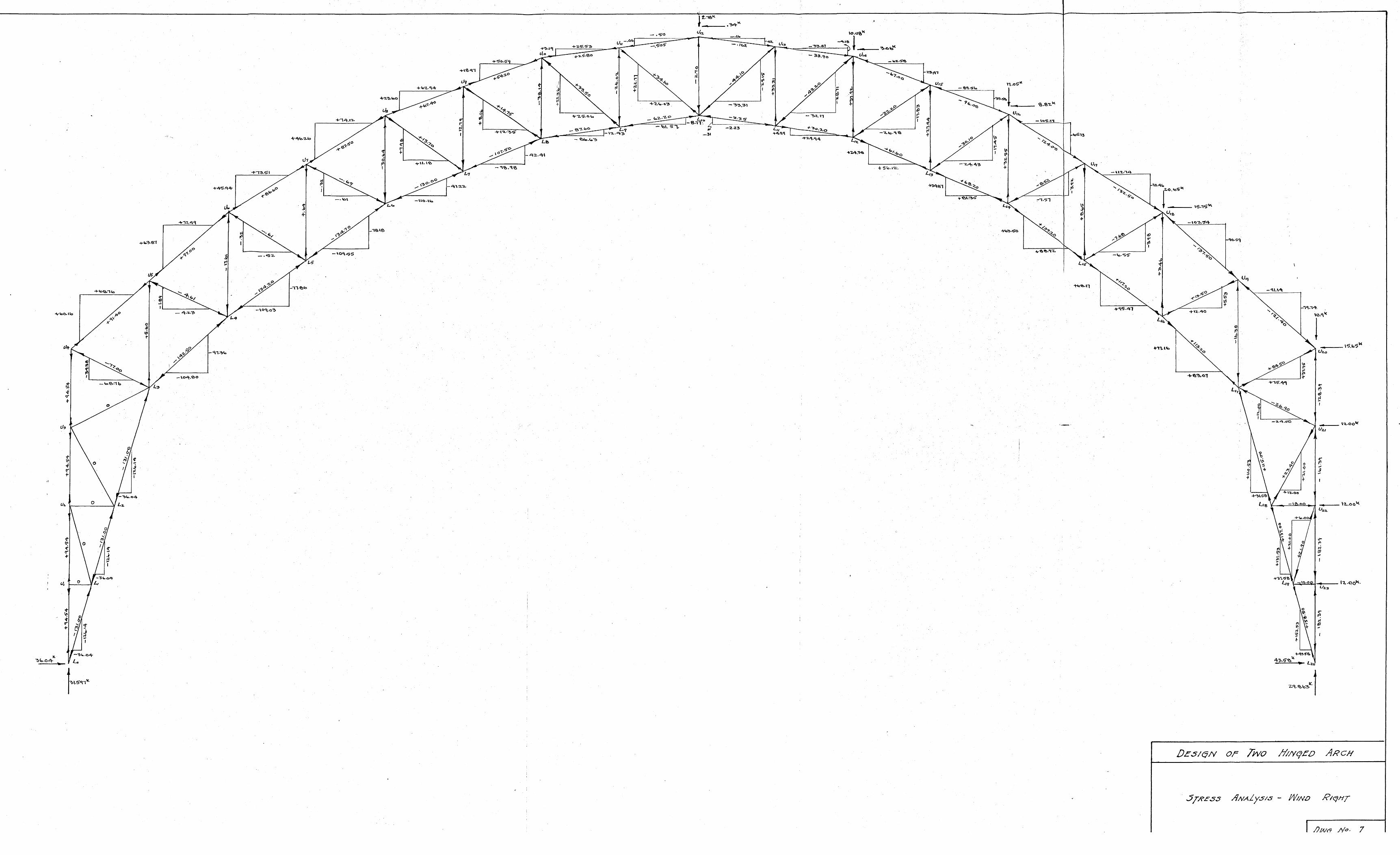

ez 1
040
(4
-- 'ak.k
04*
lyalk1
.. 2.o
-2 -7 -
-4 -
'-
4-4-2-
-1
6(4k
a3
OE/9 OF O TiVOI - /NCD RCH
5 ANt/A/yJ/3 - Sivo loAo AZ! Oy tl~e
C0o oI/oivN x =0
Il .


2
4xq e.e
s
sen.
A u
s-
/e-
%9
A..
js
406UA
77/
6
M,,
40
4
101
--7
Ot
2 x 3
di)(-r.*1- aft4
9?
Io.50444-1
-t
Z C
2 toxxh2
5 7.zz
4sit
--11) M.
-
4 Z
)9
1tto
Ns
$2
L9
~

:a.62.
4 774
$1.11 -2---4
I!..Nr.jI
~
1*
-31.67
- lb
2~5/c.~N 0f
NH /- .EAD OAD
1 vil
J40
7.
.018

1 6 's 0 A.
.. 3.3 4a
,6.94
-37,1 / .
-2/.30
.r.
- 46-. . 5
54.e 6
-7G~.77
'10
L -
0
-9
e
4!(.
vAZ/.5-5/ - Swoii ALzL4 OVER
.. 13.z.4
N
r -A '3
4.604C
02-
73 (31(
.-- 7...,.s.3 o
-- 47- .o3
I
... o .4-1 ?i
- lo-OG,
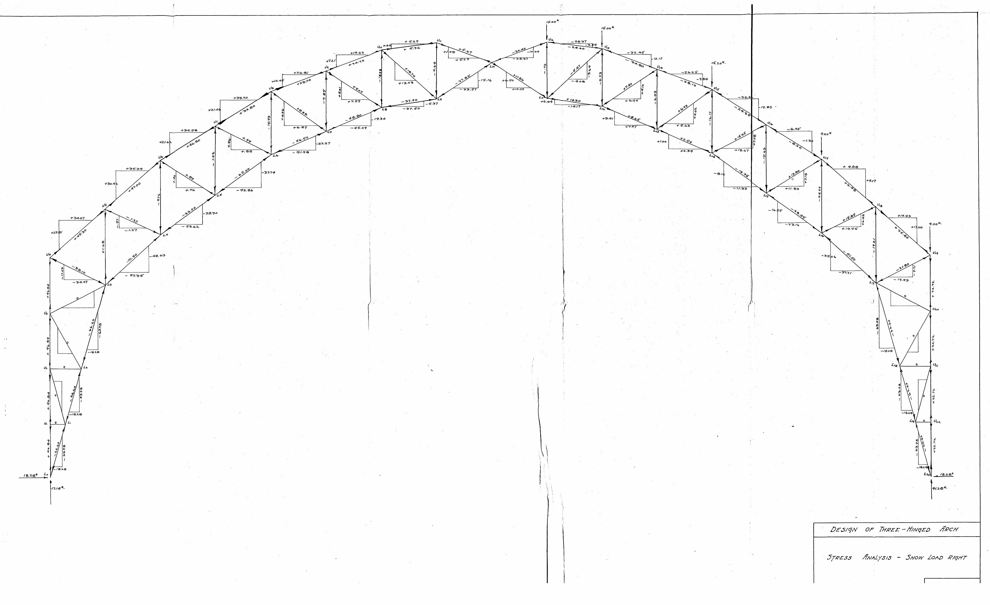
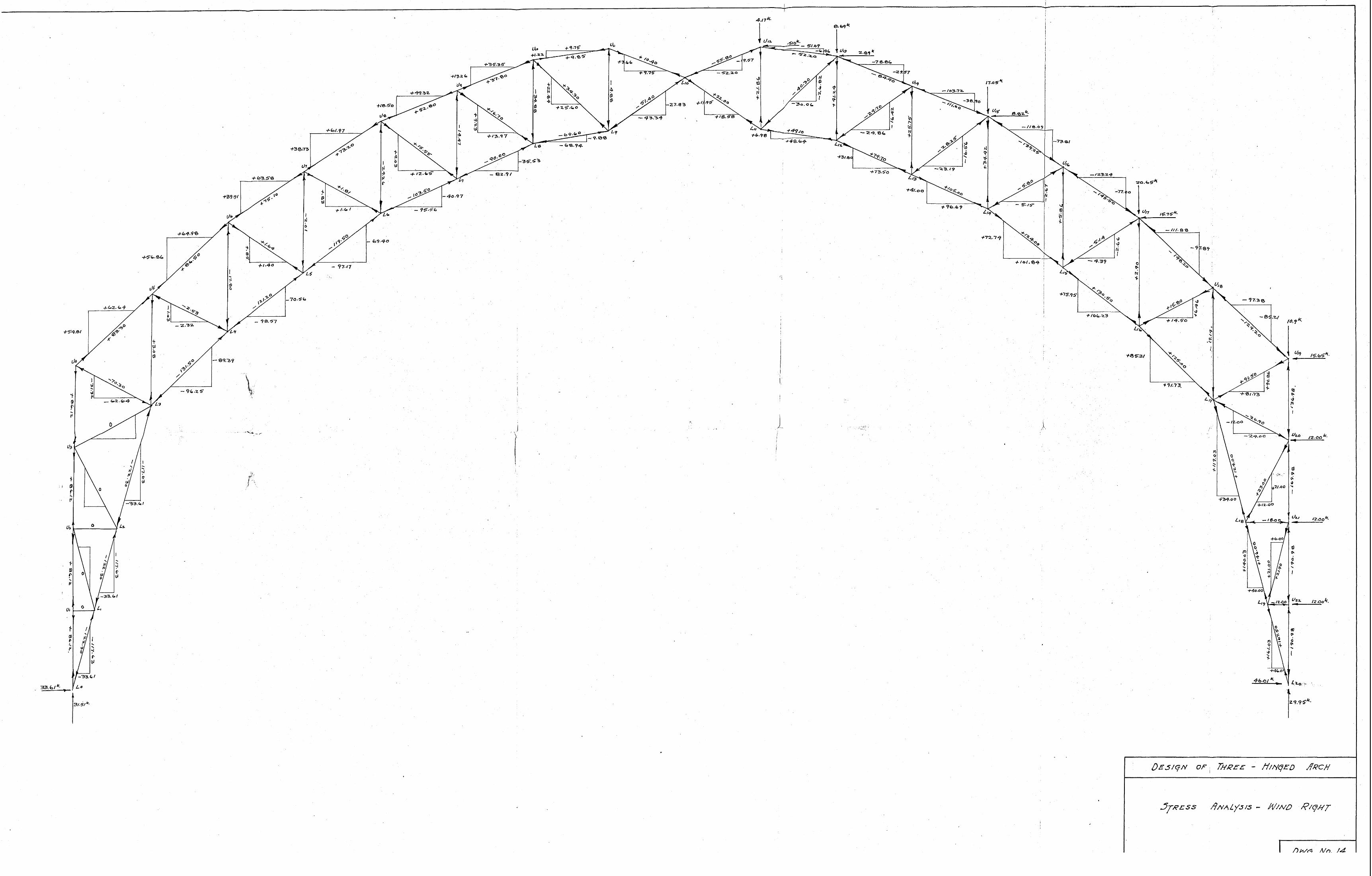
> 0
4173-
+4732
+te.~J5
7-5, 0C5
10 -40. 90
+140971
~4to
4a.a
41x 4
v 43
CL.. . ~
4-2 - (v 4
0
IV.N
tv
41
(
V
I
U,

0s
ee. ,J.
'i
4 \*9
'CV
a, %
X
2- C
V
aalb
---
F-14-
4/7- X/ 7/at:
-0
3C
+ S
0.1*
lis
eoo -
-m
-
r o
I,)~rz"40KI~4
If)
-02
ik