a comparison of micro-mechanical modeling of asphalt ...pages.mtu.edu/~qingdai/mom_2005.pdf ·...
TRANSCRIPT

A comparison of micro-mechanical modeling ofasphalt materials using finite elements and doublet mechanics
Martin H. Sadd *, Qingli Dai
Department of Mechanical Engineering and Applied Mechanics, University of Rhode Island, 92 Upper College Road,
Kingston, RI 02881, USA
Received 11 July 2003; received in revised form 27 May 2004
Abstract
A comparative study is given between two micro-mechanical models that have been developed to simulate the behav-
ior of cemented particulate materials. The first model is a discrete analytical approach called doublet mechanics that
represents a solid as an array of particles. This scheme develops analytical expressions for the micro-deformation
and stress fields between particle pairs (a doublet). The second approach is a numerical finite element method that
establishes a network of elements between neighboring cemented particles. Each element has been developed to model
the local load transfer between particles. While the two modeling schemes come from very different beginnings, they
have a fundamental similarity. However, they also have some basic differences. In order to pursue these similarities
and differences, three example problems are investigated using each modeling approach. Even with the differences,
the two model predictions of the micro-stress distributions for each example compared quite closely. These results also
indicated significant micro-structural effects that differ from continuum elasticity theory and could lead to better expla-
nations of observed failures of these types of materials.
� 2004 Elsevier Ltd. All rights reserved.
Keywords: Finite element modeling; Doublet mechanics; Asphalt concrete; Micro-mechanical modeling; Cemented particulate mate-
rials; Material micro-structure
1. Introduction
The mechanical behavior of heterogeneous sol-
ids is commonly approached from two general
viewpoints depending on whether the material
phases are distributed as either continuous or dis-crete. Under continuous distribution, theories are
0167-6636/$ - see front matter � 2004 Elsevier Ltd. All rights reserved.
doi:10.1016/j.mechmat.2004.06.004
* Corresponding author. Tel.: +1 401 874 2425; fax: +1 401
874 2355.
E-mail address: [email protected] (M.H. Sadd).
Mechanics of Materials 37 (2005) 641–662
www.elsevier.com/locate/mechmat
based on continuum mechanics and have provided
many useful solutions to problems of engineering
interest. However, these theories generally develop
models that do not contain scaling effects and this
is normally regarded as a limitation to predictingmicro-mechanical material behavior. In order to
overcome this limitation, various elegant modifica-
tions to continuum mechanics have been made to
incorporate scale and micro-structural features
into the theory. On the other hand, discrete mode-
ling develops particular micro-force–deformation
relations between the various material phases
within the solid. Thus the micro-forces are distrib-uted at specific points and along directions inher-
ently connected to the discrete micro-structural
geometry. From a fundamental point of view, such
distributions are not directly representable by
traditional tensor variables used in continuum
mechanics. Discrete models normally lead to theo-
ries with one or more length scales resulting in
non-local behavior where the stress at a point willdepend on the deformation in a neighborhood
about the point. These length scales may represent
the sizes and/or separations of particles, dimen-
sions of internal cells, characteristic ranges of
particle or phase interactions, etc.
The particular material of interest in the current
work is asphalt concrete, a complex heterogeneous
material generally composed of aggregates, binder/cement, and void space. Because of these features,
the material has particular micro-structures that
affect the load carrying behavior. Typically these
micro-structures are related to aggregate geometry
such as particle size or spacing and occur at length
scales in the range 0.1–20mm. Recently a consider-
able amount of research has been conducted on
developing micro-mechanics models to predictthe behavior of asphalt, concrete, ceramics, rock
and other cemented granular materials. This previ-
ous work can be divided into analytical and com-
putational modeling.
Past analytical work has incorporated several
types of micro-mechanical continuum mechanics
theories. Examples include Cosserat/micro-polar
theories which introduce an additional kinematicrotational degree of freedom; see review articles
by Eringen (1968, 1999) and Kunin (1983). These
theories have been applied to granular materials
by Chang and Liao (1990) and Chang and Ma
(1991, 1992). Continuum theories using higher
order displacement gradients have also been used
to develop micro-mechanical models; Bardenha-
gen and Trianfyllidis (1994) for elastic latticemodels, and Chang and Gao (1995) for granular
materials. A large volume of work has used fabric
tensor theories to characterize the material micro-
structure and relate particular fabric tensors to
the material�s constitutive stress–strain response;
e.g. Nemat-Nasser and Mehrabadi (1983), Konshi
and Naruse (1988) and Bathurst and Rothenburg
(1988). Another area of analytical modeling hasused distributed body theory whereby porous/
multiphase micro-structure is accounted for using
an additional independent volume distribution
function. The general theory for elastic materials
was established by Cowin and Nunziato (1983),
and this was followed by many application papers;
e.g. Cowin (1984). Some work has approached the
problem using statistical methods to developmodels with random variation in micro-mechani-
cal properties; e.g. Ostoja-Starzewski and Wang
(1989).
One particular theory that has recently been ap-
plied to granular and asphalt materials is the dou-
blet mechanics model. This approach originally
developed by Granik (1978), has been applied to
granular materials by Granik and Ferrari (1993)and Ferrari et al. (1997). Recently Wang et al.
(2003) presented a micro-mechanical study of
top–down cracking of asphalt materials using
some results from this theory. Doublet mechanics
is a micro-mechanical discrete model whereby sol-
ids are represented as arrays of points, particles or
nodes at finite distances. A particle pair is referred
to as a doublet, and the particle spacing introduceslength scales into the micro-structural theory. The
model develops micro-stress–strain constitutive
laws for the extensional (axial), shear and torsional
deformations between the particles in each dou-
blet. The theory has shown promise is predicting
observed behaviors that are not predictable using
continuum mechanics. These behaviors include
the so-called Flamant paradox (Ferrari et al.,1997), where in a half-space under compressive
boundary loading, continuum theory predicts a
completely compressive stress field but observa-
642 M.H. Sadd, Q. Dai / Mechanics of Materials 37 (2005) 641–662

tions indicate regions of tensile stress. Other
anomalous behaviors include dispersive wave
propagation.
Another general area of micro-mechanical
modeling has taken the numerical computationapproach using finite element (FEM), boundary
element (BEM) and discrete element (DEM) meth-
ods. Examples of finite element modeling include
Liao and Chang (1992) for granular materials,
Stankowski (1990) on cemented particulate com-
posites, and Sepehr et al. (1994) for a study on as-
phalt pavement layers. Soares et al. (2003) used
cohesive zone elements to develop micro-mechani-cal fracture model of asphalt materials. A common
FEM approach to simulate particulate and hetero-
geneous materials has used an equivalent lattice
network system to represent the inter-particle load
transfer behavior. This type of micro-structural
modeling has been used previously; Bazant et al.
(1990), Mora (1992), Sadd and Gao (1998) and
Budhu et al. (1997). Along similar lines, Guddatiet al. (2002) recently presented a random truss lat-
tice model to simulate micro-damage in asphalt
concrete, and Chang et al. (2002) used a lattice
micro-structure to develop a FEM model for
concrete failure. Bahia et al. (1999) have also used
finite elements to model the aggregate-binder re-
sponse of asphalt materials. Boundary element
applications for asphalt modeling have beenpresented by Birgisson et al. (2002). Discrete
element methods simulate particulate systems by
modeling the translational and rotational behav-
iors of each particle using Newton�s laws. DEM
studies on cemented particulate materials include
the work by Rothenburg et al. (1992), Chang
and Meegoda (1993), Trent and Margolin (1994),
Sadd et al. (1992), Sadd and Gao (1997), Buttlarand You (2001), and Ullidtz (2001).
Of special interest with respect to the current
study is the micro-mechanical finite element model
previously developed by the authors, Sadd et al.
(2004a,b). Similar to the doublet mechanics ap-
proach this computational model uses basic load
transfer mechanics between particles to establish
a numerical scheme to simulate asphalt materialbehavior. This is accomplished by first developing
a frame-type element to simulate the micro-load
carrying response between cemented aggregates.
The overall asphalt behavior is then modeled by
a network of these micro-finite elements. This
scheme has shown good success in several applica-
tions and has compared reasonably well with
experimental results.The purpose of this work is to present a com-
parison of modeling results from doublet mechan-
ics and the above mentioned finite element model.
We pursue such a comparison because of the inter-
esting similarities and differences between doublet
mechanics and the finite element approach. Each
model comes from very different beginnings, dou-
blet mechanics from a discrete analytical scheme,and finite elements based on the usual numerical
element equation model. Both schemes are based
on fundamental micro-mechanics between particle
pairs that make up the media, and each theory will
lead to the inclusion of one or more length scales.
However, there are also some important differ-
ences in each approach that warrant investigation.
After briefly reviewing the basics of the two mod-els, we apply each method to solve three basic
example problems. The first two examples will
incorporate a simplified doublet mechanics solu-
tion that has no length scale, while the final exam-
ple will use a more complete solution with a single
length scale. Each of these doublet mechanics solu-
tions is compared with a corresponding finite ele-
ment simulation of the equivalent problem.
2. Doublet mechanics
Originally developed by Granik (1978), doublet
mechanics (DM) is a micro-mechanical theory
based on a discrete material model whereby solids
are represented as arrays of points or nodes atfinite distances. A pair of such nodes is referred
to as a doublet, and the nodal spacing distances
introduce length scales into the micro-structural
theory. Current applications of the theory have
normally used regular arrays of nodal spacing thus
generating a Bravais lattice geometry. Each node
in the array is allowed to have a translation and
rotation, and increments of these variables are ex-panded in a Taylor series about the nodal point.
The order at which the series is truncated defines
the degree of approximation employed. The lowest
M.H. Sadd, Q. Dai / Mechanics of Materials 37 (2005) 641–662 643

order case using only a single term in the series will
not contain any length scales, while using more
than one term will produce a multilength scale the-
ory. This allowable kinematics develops micro-
strains of elongation, shear and torsion (aboutthe doublet axis). Through appropriate constitu-
tive assumptions, these micro-strains can be re-
lated to corresponding elongational, shear and
torsional micro-stresses.
Applications of this theory to geomechanics
problems have been given by Granik and Ferrari
(1993) and Ferrari et al. (1997). For these applica-
tions, a granular interpretation of doublet mechan-ics has been employed, in which the material is
viewed as an assembly of circular or spherical par-
ticles. A pair of such particles represents a doublet
as shown in Fig. 1. Corresponding to the doublet
(A,B) there exists a doublet or branch vector faconnecting the adjacent particle centers and defin-
ing the doublet axis a. The magnitude of this vec-
tor ga = jfaj is simply the particle diameter forparticles in contact. However, in general the parti-
cles need not be in contact, and for this case the
length scale ga could be used to represent a more
general micro-structural feature. As mentioned
the kinematics allow relative elongational, shear-
ing and torsional motions between the particles,
and this is used to develop an elongational
micro-stress pa, shear micro-stress ta, and torsionalmicro-stress ma as shown in Fig. 1. It should be
pointed out that these micro-stresses are not sec-
ond order tensors in the usual continuum mechan-
ics sense. Rather, they are vector quantities that
represent the elastic micro-forces and micro-cou-
ples of interaction between doublet particles. Their
directions are dependent on the doublet axes
which are determined by the material micro-struc-
ture. These micro-stresses are not continuously
distributed but rather exist only at particular
points in the medium being simulated by DM
theory.If u(x, t) is the displacement field coinciding
with a particle displacement, then the increment
function at x = xA (xA is the position vector of
the particle A) is written as
Dua ¼ uðxþ fa; tÞ � uðx; tÞ ð1ÞHere, a = 1, . . .,n, while n is referred to as the
valence of the Bravais lattice. Under the assump-
tion that the doublet interactions are symmetric,
the shear and torsional micro-deformations and
micro-stresses vanish, and thus only extensional
strains and stresses will exist. The extensional
micro-strain scalar measure ea, representing the
axial deformation of the doublet vector, is defined
ea ¼qa � Dua
gað2Þ
where qa = fa/ga is the unit vector in the a-direc-tion. The increment function (1) can be expanded
in a Taylor series as
Dua ¼XMm¼1
ðgaÞm
m!ðqa � rÞmuðx; tÞ þO jgaj
Mþ1� �
ð3Þ
Using this result into relation (2) develops theseries expansion for the extensional or axial
micro-strain
ea ¼ qaiXMm¼1
ðgaÞm�1
m!qak1 . . . qakm
omuioxk1 . . . oxkm
ð4Þ
where qak are the cosines of the angles between the
directions of micro-stress and the coordinates.
Fig. 1. Basic doublet geometry and micro-stress definitions.
644 M.H. Sadd, Q. Dai / Mechanics of Materials 37 (2005) 641–662

As mentioned, the number of terms used in the
series expansion of the local deformation field
determines the order of the approximation in
DM theory. For the first order case (m = 1), it
has been shown that the scaling parameter ga willdrop from the formulation, and the axial micro-
strain is reduced to
ea ¼ qaiqajeij ð5Þ
where eij is the usual continuum strain tensor given
by eij = 1/2(ui,j + uj,i).
For this case, the elastic DM solution can be
calculated directly from the corresponding iso-
tropic continuum elasticity solution through therelation
rij ¼Xna¼1
qaiqajpa ð6Þ
and this can be expressed in matrix form
frg ¼ ½Q�fpg ) fpg ¼ ½Q��1frg ð7Þ
where {r} is the continuum elastic stress vector in
rectangular Cartesian coordinates, {p} is the
micro-stress vector, and [Q] is a transformation
matrix. For plane problems, this transformation
matrix can be written as
½Q� ¼ðq11Þ
2 ðq21Þ2 ðq31Þ
2
ðq12Þ2 ðq22Þ
2 ðq32Þ2
q11q12 q21q22 q31q32
264
375 ð8Þ
where qij are the cosines of the angles between the
micro-stresses and Cartesian coordinates. This re-
sult allows a straightforward development of firstorder DM solutions for many problems of engi-
neering interest, and will be used to generate DM
solutions for comparative example problems.
Specific applications of doublet mechanics have
been developed for two-dimensional problems
with regular particle packing micro-structures.
One case that has been studied is the two-dimen-
sional hexagonal packing as shown in Fig. 2. Thisgeometrical micro-structure establishes three
Fig. 2. Two-dimensional hexagonal particle packing geometry.
M.H. Sadd, Q. Dai / Mechanics of Materials 37 (2005) 641–662 645
doublet axes at 60� angles as shown. For this caseusing only the first order approximation, the shear
and torsional micro-stresses vanish, leaving only
the elongational micro-stress components
(p1,p2,p3) as shown. Positive elongational compo-nents correspond to tensile forces between
particles.
For the second order approximation (m = 2)
case, the axial micro-strain term is now given by
ea ¼ qaiqaj ui;j þga2!qakui;jk
� �ð9Þ
Choose the simplifying case that all doublets
originating from a common node have the same
magnitudes; i.e. ga = g (a = 1, . . .,n), and alsoassume that the interactions are purely axial
(no shear or torsional micro-stresses). For
homogeneous interaction, there will be only one
micro-modulus C0, and the constitutive
relationship between elongation micro-stress and
micro-strain is expressed by pa = C0ea. The
displacement field for the second order approxi-
mation can be written
u ¼ vþ gzþ g2w ð10Þ
where v represents the solution without the lengthscale, and corresponds to the classical elasticity
solution, z and w are first order and second order
displacement fields, respectively. By applying dis-
placement equilibrium equations and length-scale
independent boundary conditions, it follows that
z � 0. The governing equation for the second
order displacement field w has been previously
given as
Xna¼1
qaiqajqakqalwj;kl ¼1
12
Xna¼1
qaiqajqakqalqapqaqvj;klpq
ð11ÞThe solutions of w can be found by using Pap-
kovich–Neuber displacement potentials. Having
determined the displacements v and w, the micro-stress can then be evaluated by
pa ¼ C0qajqak vj;k þg2qalvj;kl þ g2wj;k
� �ð12Þ
This second order theory will be used later in a
particular application/comparison problem.
3. Micro-mechanical finite element model
The basics of our micro-mechanical finite ele-
ment model have been presented in previous stud-
ies (Sadd and Dai, 2001; Sadd et al., 2004a,b).
Here we will only briefly review some of the basic
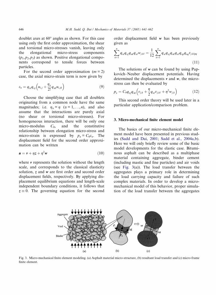
model developments for the elastic case. Bitumi-
nous asphalt can be described as a multiphase
material containing aggregate, binder cement(including mastic and fine particles) and air voids
(see Fig. 3(a)). The load transfer between the
aggregates plays a primary role in determining
the load carrying capacity and failure of such
complex materials. In order to develop a micro-
mechanical model of this behavior, proper simula-
tion of the load transfer between the aggregates
Fig. 3. Micro-mechanical finite element modeling. (a) Asphalt material micro-structure, (b) resultant load transfer and (c) micro-frame
finite element.
646 M.H. Sadd, Q. Dai / Mechanics of Materials 37 (2005) 641–662
must be accomplished. The aggregate material is
normally much stiffer than the binder, and thus
aggregates are taken as rigid particles. On the
other hand, the binder cement is a compliant mate-
rial with elastic, inelastic, and time-dependentbehaviors. In order to properly account for the
load transfer between aggregates, it is assumed
that there is an effective binder zone between
neighboring particles. It is through this zone that
the micro-mechanical load transfer occurs between
each aggregate pair. For the two-dimensional case,
this loading can be reduced to resultant normal
and tangential forces and a moment as shown inFig. 3(b). The similarities and differences in the
inter-particle load transfer for doublet mechanics
(Fig. 1) and the micro-finite element model (Fig.
3(b)) should be noted. While the normal and tan-
gential micro-forces are similar, the moment loa-
dings are not. DM theory formulates a torsional
loading about the in-plane doublet axis, while the
FEM model postulates a moment loading alongthe out-of-plane direction.
In order to model the inter-particle load trans-
fer behavior, some simplifying assumptions must
be made about allowable aggregate shape and bin-
der geometry. Aggregate geometry is commonly
quantified in terms of particle size, shape, angular-
ity and texture. However, for the present modeling
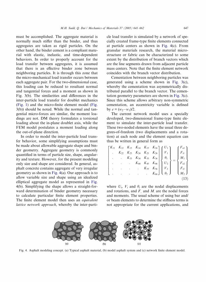
only size and shape are considered. In general, as-phalt concrete contains aggregate of very irregular
geometry as shown in Fig. 4(a). Our approach is to
allow variable size and shape using an idealized
elliptical aggregate model as represented in Fig.
4(b). Simplifying the shape allows a straight-for-
ward determination of binder geometry necessary
to calculate particular finite element properties.
The finite element model then uses an equivalent
lattice network approach, whereby the inter-parti-
cle load transfer is simulated by a network of spe-
cially created frame-type finite elements connected
at particle centers as shown in Fig. 4(c). From
granular materials research, the material micro-
structure or fabric can be characterized to someextent by the distribution of branch vectors which
are the line segments drawn from adjacent particle
mass centers. Note that the finite element network
coincides with the branch vector distribution.
Cementation between neighboring particles was
generated using a scheme shown in Fig. 3(c),
whereby the cementation was asymmetrically dis-
tributed parallel to the branch vector. The cemen-tation geometry parameters are shown in Fig. 3(c).
Since this scheme allows arbitrary non-symmetric
cementation, an eccentricity variable is defined
by e = (w2�w1)/2.
The current network model uses a specially
developed, two-dimensional frame-type finite ele-
ment to simulate the inter-particle load transfer.
These two-noded elements have the usual three de-grees-of-freedom (two displacements and a rota-
tion) at each node and the element equation can
thus be written in general form as
K11 K12 K13 K14 K15 K16
: K22 K23 K24 K25 K26
: : K33 K34 K35 K36
: : : K44 K45 K46
: : : : K55 K56
: : : : : K66
2666666664
3777777775
U 1
V 1
h1U 2
V 2
h2
8>>>>>>>><>>>>>>>>:
9>>>>>>>>=>>>>>>>>;
¼
F n1
F t1
M1
F n2
F t2
M2
8>>>>>>>><>>>>>>>>:
9>>>>>>>>=>>>>>>>>;
ð13Þ
where Ui, Vi and hi are the nodal displacements
and rotations, and F.. and M. are the nodal forces
and moments. The usual scheme of using bar and/
or beam elements to determine the stiffness terms is
not appropriate for the current applications, and
Fig. 4. Asphalt modeling concept. (a) Typical asphalt material, (b) model asphalt system and (c) network finite element model.
M.H. Sadd, Q. Dai / Mechanics of Materials 37 (2005) 641–662 647
therefore these terms were determined using an
approximate elasticity solution from Dvorkin
et al. (1994) for the stress distribution in a cement
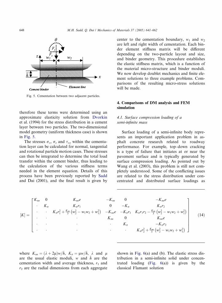
layer between two particles. The two-dimensional
model geometry (uniform thickness case) is shown
in Fig. 5.The stresses rx, rz and sxz within the cementa-
tion layer can be calculated for normal, tangential
and rotational particle motion cases. These stresses
can then be integrated to determine the total load
transfer within the cement binder, thus leading to
the calculation of the various stiffness terms
needed in the element equation. Details of this
process have been previously reported by Saddand Dai (2001), and the final result is given by
where Knn ¼ ðkþ 2lÞw=�h, Ktt ¼ lw=�h, k and lare the usual elastic moduli, w and �h are the
cementation width and average thickness, r1 and
r2 are the radial dimensions from each aggregate
center to the cementation boundary, w1 and w2
are left and right width of cementation. Each bin-
der element stiffness matrix will be different
depending on the two-particle layout and size,
and binder geometry. This procedure establishesthe elastic stiffness matrix, which is a function of
the material micro-structure and binder moduli.
We now develop doublet mechanics and finite ele-
ment solutions to three example problems. Com-
parisons of the resulting micro-stress solutions
will be made.
4. Comparisons of DM analysis and FEM
simulation
4.1. Surface compression loading of a
semi-infinite mass
Surface loading of a semi-infinite body repre-
sents an important application problem in as-phalt concrete research related to roadway
performance. For example, top–down cracking
is a type of failure that initiates at or near the
pavement surface and is typically generated by
surface compression loading. As pointed out by
Wang et al. (2003), this problem is still not com-
pletely understood. Some of the conflicting issues
are related to the stress distribution under con-centrated and distributed surface loadings as
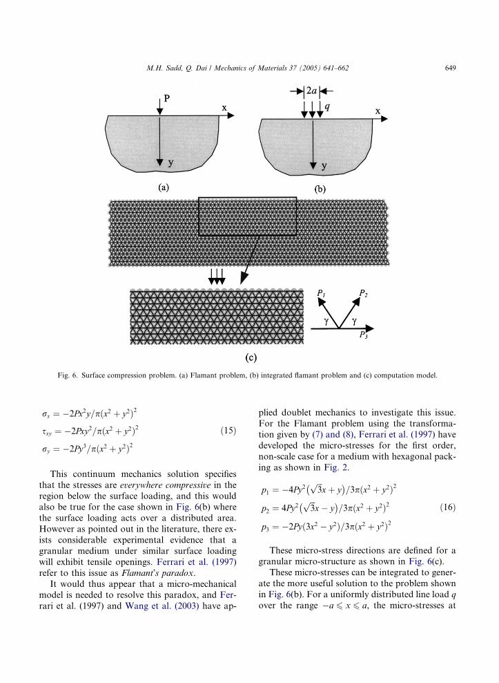
shown in Fig. 6(a) and (b). The elastic stress dis-
tribution in a semi-infinite solid under concen-
trated loading (Fig. 6(a)) is given by the
classical Flamant solution
½K� ¼
Knn 0 Knne �Knn 0 �Knne
� Ktt Kttr1 0 �Ktt Kttr2� � Kttr21 þ Knn
3w2
2 � w1w2 þ w21
� ��Knne �Kttr1 Kttr1r2 � Knn
3w2
2 � w1w2 þ w21
� �
� � � Knn 0 Knne
� � � � Ktt �Kttr2� � � � � Kttr22 þ Knn
3w2
2 � w1w2 þ w21
� �
2666666664
3777777775
ð14Þ
Fig. 5. Cementation between two adjacent particles.
648 M.H. Sadd, Q. Dai / Mechanics of Materials 37 (2005) 641–662
rx ¼ �2Px2y=pðx2 þ y2Þ2
sxy ¼ �2Pxy2=pðx2 þ y2Þ2
ry ¼ �2Py3=pðx2 þ y2Þ2ð15Þ
This continuum mechanics solution specifies
that the stresses are everywhere compressive in the
region below the surface loading, and this wouldalso be true for the case shown in Fig. 6(b) where
the surface loading acts over a distributed area.
However as pointed out in the literature, there ex-
ists considerable experimental evidence that a
granular medium under similar surface loading
will exhibit tensile openings. Ferrari et al. (1997)
refer to this issue as Flamant�s paradox.It would thus appear that a micro-mechanical
model is needed to resolve this paradox, and Fer-
rari et al. (1997) and Wang et al. (2003) have ap-
plied doublet mechanics to investigate this issue.
For the Flamant problem using the transforma-tion given by (7) and (8), Ferrari et al. (1997) have
developed the micro-stresses for the first order,
non-scale case for a medium with hexagonal pack-
ing as shown in Fig. 2.
p1 ¼ �4Py2ffiffiffi3
pxþ y
� �=3pðx2 þ y2Þ2
p2 ¼ 4Py2ffiffiffi3
px� y
� �=3pðx2 þ y2Þ2
p3 ¼ �2Pyð3x2 � y2Þ=3pðx2 þ y2Þ2ð16Þ
These micro-stress directions are defined for a
granular micro-structure as shown in Fig. 6(c).These micro-stresses can be integrated to gener-
ate the more useful solution to the problem shown
in Fig. 6(b). For a uniformly distributed line load q
over the range �a 6 x 6 a, the micro-stresses at
Fig. 6. Surface compression problem. (a) Flamant problem, (b) integrated flamant problem and (c) computation model.
M.H. Sadd, Q. Dai / Mechanics of Materials 37 (2005) 641–662 649

location (x,y) can be obtained by integration over
the coordinate origin variable u as
Although these DM micro-stresses actually ex-
ist only at discrete points and directions in the do-
main, we will use these results to make continuous
contour and x–y plots over the domain under
study. A similar statement would also apply for
the finite element micro-forces to be developed
next.
In order to generate a similar model for finiteelement simulation, a 2D-hexagonal Bravais lat-
tice structure was generated using a MATLAB
Material Generator Code. This model had 1296
circular particles and 3709 micro-frame elements
as shown in Fig. 6(c). Chosen model parameters
include: k = 0.58 MPa, l = 0.38 MPa, w1 = w2 =
4mm, h0 = 1mm, and particle size D = 10mm.
For the integrated Flamant problem, three centralparticles on the boundary had prescribed verti-
cal compressive loading and zero horizontal dis-
placement. Particles on the bottom layer were
supported with a very stiff vertical spring founda-
tion (compared with the asphalt binder stiffness).
Boundary particles on the vertical sides were un-
loaded and not constrained. To avoid boundary
effects present in the FEM model, only the centralportion of the domain (indicated by box in Fig.
6(c)) was used to compare with the doublet
mechanics results.
Micro-structural finite element simulation was
then conducted on this model, and the elastic nor-
mal axial force of each micro-frame element was
computed from the code. In order to compare fi-
nite element results with the corresponding dou-
blet mechanics predictions, the DM micro-
stresses from Eq. (17) were calculated at the
mid-point of each element. It should be noted
that the directions of these micro-stresses coincide
with the element axial forces. Fig. 7 shows com-
parisons between DM micro-stress contours and
FEM micro-force distributions for this problem.Plus and minus signs indicate regions of tensile
and compressive micro-stresses. It is observed that
the DM micro-stress and FEM micro-force con-
tours are quite similar. Comparable tensile zones
exist for each micro-stress–force distribution, thus
indicating possible regions of tensile or mode I
fracture behavior. Tensile zones for the P1 and
P2 distributions are located adjacent to the sur-face loading, and these have been observed re-
gions of surface or top–down cracking behavior.
It is also evident that a significant zone of hori-
zontal tensile micro-stress (P3), is located directly
below the loading. According to each theory, the
maximum value of this tensile field appears to be
located at a somewhat different location below the
loading surface. Clearly this location would bedependent on the fact that the DM solution is
for a semi-infinite half space, while the FEM
model has used particular dimensions and bound-
ary conditions for the asphalt domain. Since the
continuum elasticity case predicts only a compres-
P 1 ¼Z a
�ap1ðx� uÞdu ¼
Z a
�a�4qy2
ffiffiffi3
pðx� uÞ þ y
� �3p ðx� uÞ2 þ y2� �2� ��1
du
¼ 2qy3p
ffiffi3
py�x�a
ðxþaÞ2þy2�
ffiffi3
py�xþa
ðx�aÞ2þy2� 1
y tan�1 xþa
y
� �þ 1
y tan�1 x�a
y
� �h i
P 2 ¼Z a
�ap2ðx� uÞdu ¼
Z a
�a4qy2
ffiffiffi3
pðx� uÞ � y
� �3p ðx� uÞ2 þ y2� �2� ��1
du
¼ � 2qy3p
ffiffi3
pyþxþa
ðxþaÞ2þy2�
ffiffi3
pyþx�a
ðx�aÞ2þy2þ 1
y tan�1 xþa
y
� �� 1
y tan�1 x�a
y
� �h i
P 3 ¼Z a
�ap3ðx� uÞdu ¼
Z a
�a�2qyð3ðx� uÞ2 � y2Þ 3p ðx� uÞ2 þ y2
� �2� ��1
du
¼ 2qy3p
2xþ2aðxþaÞ2þy2
� 2x�2aðx�aÞ2þy2
� 1y tan
�1 xþay
� �þ 1
y tan�1 x�a
y
� �h i
ð17Þ
650 M.H. Sadd, Q. Dai / Mechanics of Materials 37 (2005) 641–662

sive stress field, these tensile stress regions are
attributable to the micro-mechanical modeling
through the inter-particle mechanics based oneither doublet mechanics or finite element simula-
tion. Of course material failure could also occur
via shearing or mode II fracture at other locations
in the model.
4.2. Void under uniform compression
The existence of voids in asphalt pavementsresulting from improper compaction or entrap-
ment of spurious material is another important
issue related to roadway failure. Voids can raise
the local stress field and produce fatigue or frac-
ture failures emanating from the void boundary.
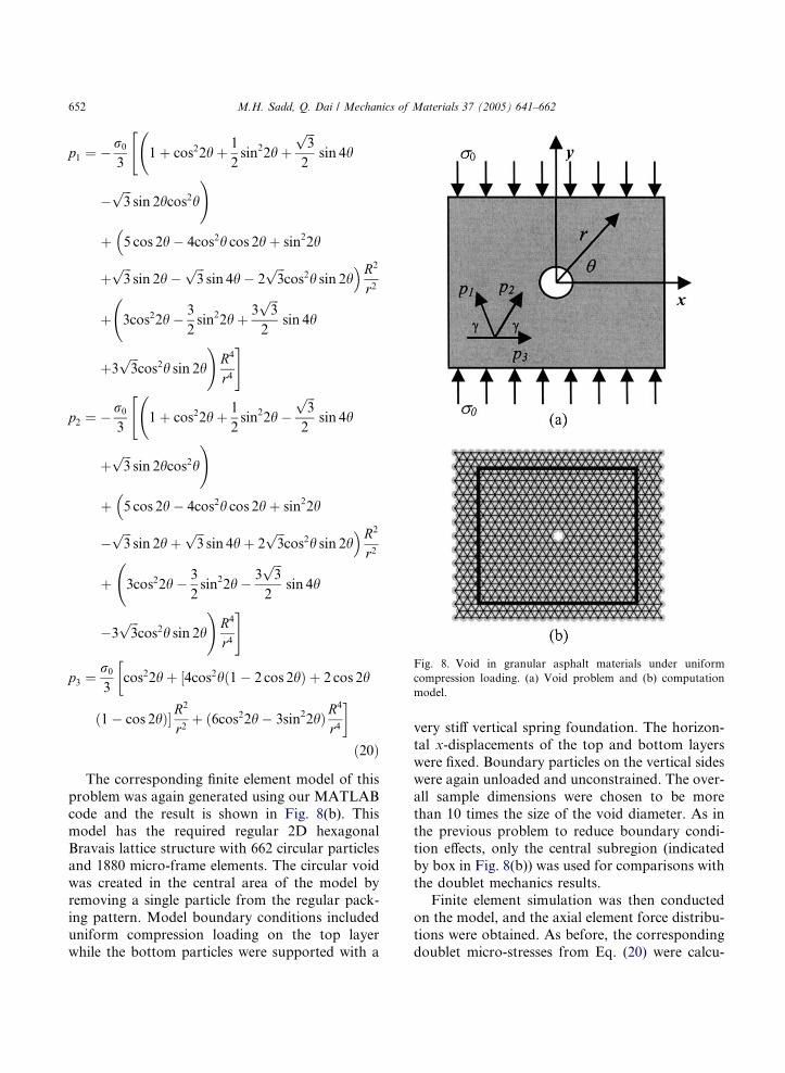
We wish to consider the problem of a circular
void in an asphalt material under uniform far-
field compression loading as shown in Fig. 8(a).The primary goal of this example is to investi-
gate the elevation of micro-stresses around the
void, and to look for zones of possible tensile
behavior.
The continuum elastic stress distribution
around a circular hole under uniform far-field
compression r0 as shown in Fig. 8(a) may be found
in any standard elasticity text and is given in polar
coordinates as
rr ¼ � r02
1� R2
r2
� �þ r0
21þ 3R4
r4 � 4R2
r2
� �cos 2h
rh ¼ � r02
1þ R2
r2
� �� r0
21þ 3R4
r4
� �cos 2h
srh ¼ � r02
1� 3R4
r4 þ 2R2
r2
� �sin 2h ð18Þ
where R is the radius of the hole and r and h are
the usual polar coordinates.
To obtain the DM micro-stresses from the con-tinuum field using transformation relation (7), the
polar coordinate stresses need to be first trans-
formed to Cartesian components. The micro-stress
directions for the problem (hexagonal Bravais lat-
tice) are shown in Fig. 8(a), and thus the transfor-
mation matrix Q can be expressed as
½Q� ¼cos2c cos2c 1
sin2c sin2c 0
� cos c sin c cos c sin c 0
264
375 ð19Þ
where the doublet structure angle c = 60� for this
case. Applying these appropriate transformations,
the DM micro-stresses become
Fig. 7. Comparison of DM analysis and FEM results for integrated flamant problem.
M.H. Sadd, Q. Dai / Mechanics of Materials 37 (2005) 641–662 651
p1 ¼ � r0
3
" 1þ cos22hþ 1
2sin22hþ
ffiffiffi3
p
2sin 4h
�ffiffiffi3
psin 2hcos2h
!
þ�5 cos 2h� 4cos2h cos 2hþ sin22h
þffiffiffi3
psin 2h�
ffiffiffi3
psin 4h� 2
ffiffiffi3
pcos2h sin 2h
�R2
r2
þ 3cos22h� 3
2sin22hþ 3
ffiffiffi3
p
2sin 4h
þ3ffiffiffi3
pcos2h sin 2h
!R4
r4
#
p2 ¼ � r0
31þ cos22hþ 1
2sin22h�
ffiffiffi3
p
2sin 4h
"
þffiffiffi3
psin 2hcos2h
!
þ�5 cos 2h� 4cos2h cos 2hþ sin22h
�ffiffiffi3
psin 2hþ
ffiffiffi3
psin 4hþ 2
ffiffiffi3
pcos2h sin 2h
�R2
r2
þ 3cos22h� 3
2sin22h� 3
ffiffiffi3
p
2sin 4h
�3ffiffiffi3
pcos2h sin 2h
!R4
r4
#
p3 ¼r0
3
�cos22hþ ½4cos2hð1� 2 cos 2hÞ þ 2 cos 2h
ð1� cos 2hÞ�R2
r2þ ð6cos22h� 3sin22hÞR
4
r4
�
ð20Þ
The corresponding finite element model of this
problem was again generated using our MATLAB
code and the result is shown in Fig. 8(b). This
model has the required regular 2D hexagonal
Bravais lattice structure with 662 circular particlesand 1880 micro-frame elements. The circular void
was created in the central area of the model by
removing a single particle from the regular pack-
ing pattern. Model boundary conditions included
uniform compression loading on the top layer
while the bottom particles were supported with a
very stiff vertical spring foundation. The horizon-
tal x-displacements of the top and bottom layers
were fixed. Boundary particles on the vertical sides
were again unloaded and unconstrained. The over-
all sample dimensions were chosen to be more
than 10 times the size of the void diameter. As in
the previous problem to reduce boundary condi-tion effects, only the central subregion (indicated
by box in Fig. 8(b)) was used for comparisons with
the doublet mechanics results.
Finite element simulation was then conducted
on the model, and the axial element force distribu-
tions were obtained. As before, the corresponding
doublet micro-stresses from Eq. (20) were calcu-
Fig. 8. Void in granular asphalt materials under uniform
compression loading. (a) Void problem and (b) computation
model.
652 M.H. Sadd, Q. Dai / Mechanics of Materials 37 (2005) 641–662
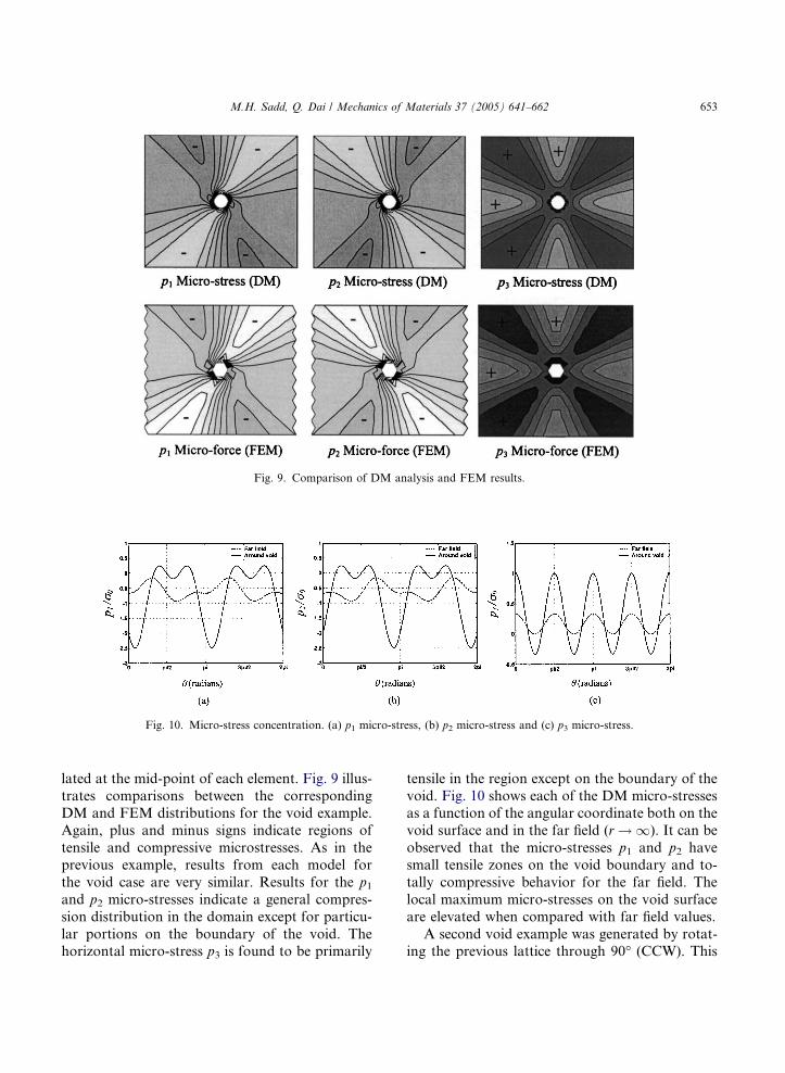
lated at the mid-point of each element. Fig. 9 illus-
trates comparisons between the correspondingDM and FEM distributions for the void example.
Again, plus and minus signs indicate regions of
tensile and compressive microstresses. As in the
previous example, results from each model for
the void case are very similar. Results for the p1and p2 micro-stresses indicate a general compres-
sion distribution in the domain except for particu-
lar portions on the boundary of the void. Thehorizontal micro-stress p3 is found to be primarily
tensile in the region except on the boundary of the
void. Fig. 10 shows each of the DM micro-stressesas a function of the angular coordinate both on the
void surface and in the far field (r ! 1). It can be
observed that the micro-stresses p1 and p2 have
small tensile zones on the void boundary and to-
tally compressive behavior for the far field. The
local maximum micro-stresses on the void surface
are elevated when compared with far field values.
A second void example was generated by rotat-ing the previous lattice through 90� (CCW). This
Fig. 9. Comparison of DM analysis and FEM results.
Fig. 10. Micro-stress concentration. (a) p1 micro-stress, (b) p2 micro-stress and (c) p3 micro-stress.
M.H. Sadd, Q. Dai / Mechanics of Materials 37 (2005) 641–662 653
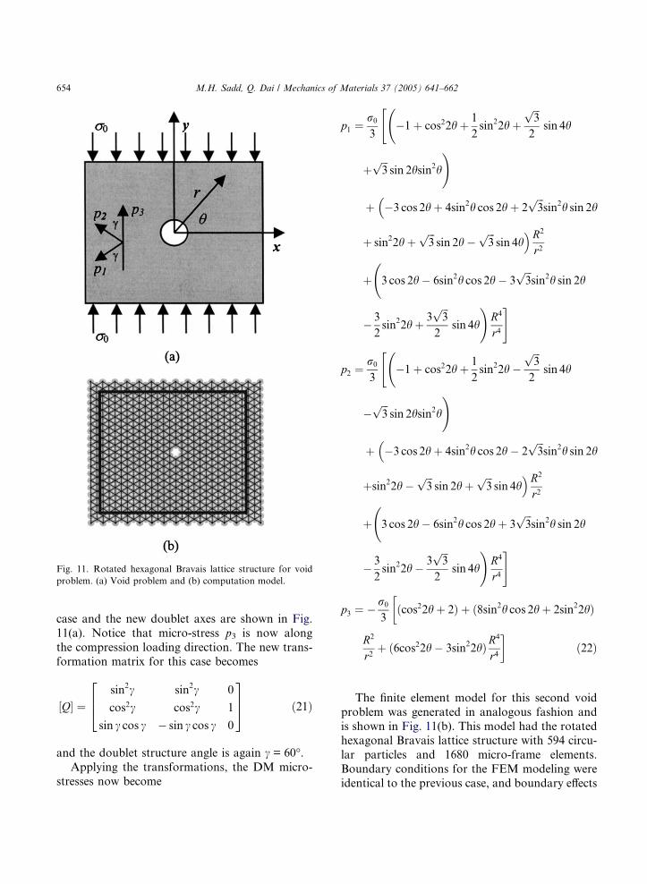
case and the new doublet axes are shown in Fig.
11(a). Notice that micro-stress p3 is now along
the compression loading direction. The new trans-
formation matrix for this case becomes
½Q� ¼sin2c sin2c 0
cos2c cos2c 1
sin c cos c � sin c cos c 0
264
375 ð21Þ
and the doublet structure angle is again c = 60�.Applying the transformations, the DM micro-
stresses now become
p1 ¼r0
3�1þ cos22hþ 1
2sin22hþ
ffiffiffi3
p
2sin 4h
"
þffiffiffi3
psin 2hsin2h
!
þ �3 cos 2hþ 4sin2h cos 2hþ 2ffiffiffi3
psin2h sin 2h
�
þ sin22hþffiffiffi3
psin 2h�
ffiffiffi3
psin 4h
�R2
r2
þ 3 cos 2h� 6sin2h cos 2h� 3
ffiffiffi3
psin2h sin 2h
� 3
2sin22hþ 3
ffiffiffi3
p
2sin 4h
!R4
r4
#
p2 ¼r0
3�1þ cos22hþ 1
2sin22h�
ffiffiffi3
p
2sin 4h
"
�ffiffiffi3
psin 2hsin2h
!
þ �3 cos 2hþ 4sin2h cos 2h� 2ffiffiffi3
psin2h sin 2h
�
þsin22h�ffiffiffi3
psin 2hþ
ffiffiffi3
psin 4h
�R2
r2
þ 3 cos 2h� 6sin2h cos 2hþ 3
ffiffiffi3
psin2h sin 2h
� 3
2sin22h� 3
ffiffiffi3
p
2sin 4h
!R4
r4
#
p3 ¼ � r0
3
�ðcos22hþ 2Þ þ ð8sin2h cos 2hþ 2sin22hÞ
R2
r2þ ð6cos22h� 3sin22hÞR
4
r4
�ð22Þ
The finite element model for this second void
problem was generated in analogous fashion and
is shown in Fig. 11(b). This model had the rotatedhexagonal Bravais lattice structure with 594 circu-
lar particles and 1680 micro-frame elements.
Boundary conditions for the FEM modeling were
identical to the previous case, and boundary effects
Fig. 11. Rotated hexagonal Bravais lattice structure for void
problem. (a) Void problem and (b) computation model.
654 M.H. Sadd, Q. Dai / Mechanics of Materials 37 (2005) 641–662

were minimized by only considering the domain
interior to the box shown in Fig. 11(b). Fig. 12
shows the comparisons between DM and FEM dis-
tributions for the rotated void example. As in the
previous cases, results from each model are similar.
It is observed from the p1 and/or p2 contours that
each model generates tensile micro-stress domainsunder the uniform compressional loading. These
tension domains are caused by the presence of the
void. If the void is removed, the tension zones dis-
appear and the p1 and p2 fields are totally compres-
sive. It appears that the zone of maximum tensile
micro-stress p1 or p2 lies approximately along the
direction of the corresponding doublet axis. Since
the micro-stress p3 lies along the compressional
loading direction, it has only compression action
within model domain. Along a horizontal line(h = 0), p3 increases significantly as one approaches
the void. As shown in Fig. 13, the micro-stress dis-
tributions were again investigated as a function of
Fig. 12. Comparison of DM and FEM analysis for rotated lattice structure.
Fig. 13. Micro-stresses concentration. (a) p1 micro-stress, (b) p2 micro-stress and (c) p3 micro-stress.
M.H. Sadd, Q. Dai / Mechanics of Materials 37 (2005) 641–662 655
the angular coordinate on the void boundary and
at far field. It can be observed that the micro-stres-
ses p1 and p2 have tensile zones on the void bound-
ary while p3 exhibits totally compressive behavior
on the void and at far-field.For the void problem shown in Fig. 8, the p3
micro-stress distribution around the void shown
in Fig. 10(c) indicates a range of �r0/3 6 p3 6 r0,while the far-field variation is given by 0 6 p3 6 r0/3. Thus in the horizontal direction (h = 0), the
local value of this micro-stress is three times higher
than the far-field value. Likewise, for the void
problem of Fig. 11, the ranges of p3 are shown inFig. 13(c) and would be �3r0 6 p3 6 0 around
the void and �r0 6 p3 6 2r0/3 for the far-field.
For this case, the stress concentration factor for
the vertical p3 micro-stress is three which matches
with classical continuum elasticity result.
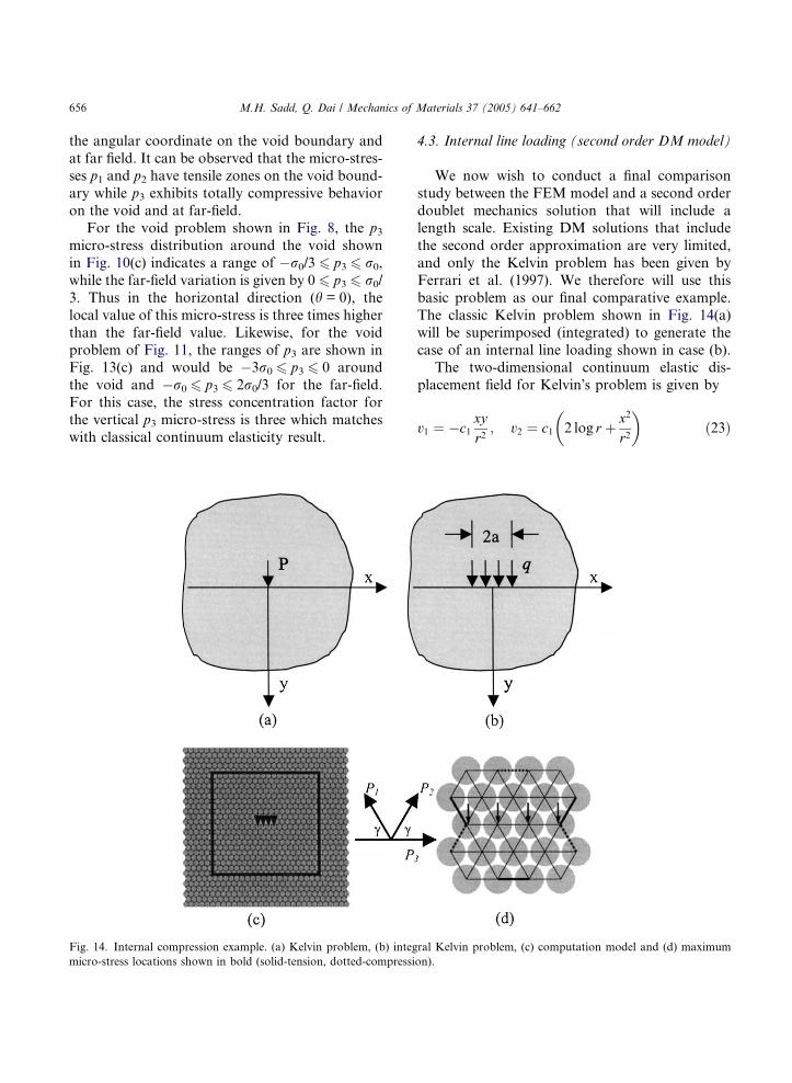
4.3. Internal line loading (second order DM model)
We now wish to conduct a final comparison
study between the FEM model and a second order
doublet mechanics solution that will include alength scale. Existing DM solutions that include
the second order approximation are very limited,
and only the Kelvin problem has been given by
Ferrari et al. (1997). We therefore will use this
basic problem as our final comparative example.
The classic Kelvin problem shown in Fig. 14(a)
will be superimposed (integrated) to generate the
case of an internal line loading shown in case (b).The two-dimensional continuum elastic dis-
placement field for Kelvin�s problem is given by
v1 ¼ �c1xyr2
; v2 ¼ c1 2 log r þ x2
r2
� ð23Þ
Fig. 14. Internal compression example. (a) Kelvin problem, (b) integral Kelvin problem, (c) computation model and (d) maximum
micro-stress locations shown in bold (solid-tension, dotted-compression).
656 M.H. Sadd, Q. Dai / Mechanics of Materials 37 (2005) 641–662
where r2 = x2 + y2, c1 ¼ 4P=9Ep, and E is the
modulus of elasticity. The second order displace-
ment field was formulated by Ferrari et al. (1997)
w1 ¼ c19y 64 x7
r10 � 96 x5
r8 þ 32 x3
r6 þ xr4
� �
w2 ¼ � c118
128 x8
r10 � 352 x6
r8 þ 320 x4
r6 � 100 x2
r4 þ 5r2
� �
ð24Þ
Thus from relation (10) with z = 0, the second
order displacement field for the Kelvin problem
can be expressed as
u1 ¼ v1 þ g2w1; u2 ¼ v2 þ g2w2 ð25ÞThe micro-stresses for the second order case of
the structure angle c = 60� can be developed from
Eq. (12) with C0 = E,
p1 ¼P
81pðx2 þ y2Þ6hg2�12x8y þ 444x2y7 � 780x4y5
þ 52x6y3 � 504ffiffiffi3
px5y4 þ 84
ffiffiffi3
px7y2 � 102
ffiffiffi3
pxy8
þ 588ffiffiffi3
px3y6 � 2
ffiffiffi3
px9 � 16y9
�
þ g 108xy9 þ 288x3y7 þ 216x5y5 � 36x9y� �
� 9ffiffiffi3
px11 þ 45y11 þ 189x2y9 þ 306x4y7
�
þ 234x6y5 þ 81x8y3 þ 9x10y þ 306ffiffiffi3
px5y6
þ 189ffiffiffi3
px3y8 þ 45
ffiffiffi3
pxy10 þ 234
ffiffiffi3
px7y4
þ 81ffiffiffi3
px9y2
�ið26Þ
p2 ¼P
81pðx2 þ y2Þ6hg2�12x8y þ 444x2y7 � 780x4y5
þ 52x6y3 þ 504ffiffiffi3
px5y4 � 84
ffiffiffi3
px7y2 þ 102
ffiffiffi3
pxy8
� 588ffiffiffi3
px3y6 þ 2
ffiffiffi3
px9 � 16y9
�
þ g �108xy9 � 288x3y7 � 216x5y5 þ 36x9y� �
þ 9ffiffiffi3
px11 � 45y11 � 189x2y9 � 306x4y7
�
� 234x6y5 � 81x8y3 � 9x10y þ 306ffiffiffi3
px5y6
þ 189ffiffiffi3
px3y8 þ 45
ffiffiffi3
pxy10 þ 234
ffiffiffi3
px7y4
þ 81ffiffiffi3
px9y2
�ið27Þ
p3 ¼4Py
81pðx2 þ y2Þ6g2 3x8 � 152x6y2 þ 390x4y4�
�96x2y6 � y8�þ g �9x9 þ 54x5y4�
þ72x3y6 þ 27xy8�þ �9x10 � 27x8y2�
þ18x4y6 � 18x6y4 þ 27x2y8 þ 9y10��
ð28Þ
where the micro-stress directions are defined inFig. 14(c).
We now wish to develop the solution for a uni-
formly distributed line load q over the range
�a 6 x 6 a (at y = 0) as shown in Fig. 14(b). This
can be accomplished as before by integrating the
micro-stresses at location (x,y) over the coordinate
origin variable u as
P 1 ¼Z a
�ap1ðx� uÞdu
¼ q
324p ðxþ aÞ2 þ y2� �5 g2 12y8 þ 6ðxþ aÞ8
��
þ64ðxþ aÞy7 � 400ðxþ aÞ3y5 þ 64ðxþ aÞ5y3
�246ðxþ aÞ2y6 þ 390ðxþ aÞ4y4 � 114ðxþ aÞ6y2
þ16ðxþ aÞ7y�þ g �144ðxþ aÞ2y7�
þ144ðxþ aÞ6y3 þ 72ðxþ aÞ8y � 72y9�
þ 108y10 þ 108ðxþ aÞ8y2 þ 432ðxþ aÞ6y4
þ 648ðxþ aÞ4y6 þ 432ðxþ aÞ2y8 þ 72ðxþ aÞ9y
þ 288ðxþ aÞ7y3 þ 432ðxþ aÞ5y5 þ 288ðxþ aÞ3y7
þ 72ðxþ aÞy9 þ 108tan�1 xþ ay
� y10
� 27 ln ðxþ aÞ2 þ y2� �
ðxþ aÞ10
� 27 ln ðxþ aÞ2 þ y2� �
y10 þ 108tan�1 xþ ay
�
� ðxþ aÞ10 � 135 ln ðxþ aÞ2 þ y2� �
ðxþ aÞ2y8
þ 540tan�1 xþ ay
� ðxþ aÞ2y8
� 135 ln ðxþ aÞ2 þ y2� �
ðxþ aÞ8y2
þ 1080tan�1 xþ ay
� ðxþ aÞ6y4
M.H. Sadd, Q. Dai / Mechanics of Materials 37 (2005) 641–662 657

þ 540tan�1 xþ ay
� ðxþ aÞ8y2
� 270 ln ðxþ aÞ2 þ y2� �
ðxþ aÞ6y4
� 270 ln ðxþ aÞ2 þ y2� �
ðxþ aÞ4y6
þ1080tan�1 xþ ay
� ðxþ aÞ4y6
�
� q
324p ðx� aÞ2 þ y2� �5 g2 12y8 þ 6ðx� aÞ8
��
þ64ðx� aÞy7 � 400ðx� aÞ3y5 þ 64ðx� aÞ5y3
�246ðx� aÞ2y6 þ 390ðx� aÞ4y4 � 114ðx� aÞ6y2
þ16ðx� aÞ7y�þ g �144ðx� aÞ2y7�
þ144ðx� aÞ6y3 þ 72ðx� aÞ8y � 72y9�þ 108y10
þ108ðx� aÞ8y2 þ 432ðx� aÞ6y4 þ 648ðx� aÞ4y6
þ 432ðx� aÞ2y8 þ 72ðx� aÞ9y þ 288ðx� aÞ7y3
þ 432ðx� aÞ5y5 þ 288ðx� aÞ3y7 þ 72ðx� aÞy9
þ 108tan�1 x� ay
� y10 � 27 ln ðx� aÞ2 þ y2
� �
� ðx� aÞ10 � 27 ln ðx� aÞ2 þ y2� �
y10
þ 108tan�1 x� ay
� ðx� aÞ10 � 135 ln ðx� aÞ2
�
þy2�ðx� aÞ2y8 þ 540tan�1 x� a
y
� ðx� aÞ2y8
� 135 ln ðx� aÞ2 þ y2� �
ðx� aÞ8y2
þ 1080tan�1 x� ay
� ðx� aÞ6y4
þ 540tan�1 x� ay
� ðx� aÞ8y2
� 270 ln ðx� aÞ2 þ y2� �
ðx� aÞ6y4
� 270 ln ðx� aÞ2 þ y2� �
ðx� aÞ4y6
þ1080tan�1 x� ay
� ðx� aÞ4y6
�ð29Þ
P 3 ¼Z a
�ap3ðx� uÞdu
¼ � 2qy
81p ðxþ aÞ2 þ y2� �5 g2 58ðxþ aÞ5y2
�h
�70ðxþ aÞ3y4 � 2ðxþ aÞy6 � 2ðxþ aÞ7�
þ g 9y8 þ 18ðxþ aÞ2y6 � 18ðxþ aÞ6y2�
�9ðxþ aÞ8�þ 18ðxþ aÞ9 þ 72ðxþ aÞ7y2
þ108ðxþ aÞ5y4 þ 72ðxþ aÞ3y6 þ 18ðxþ aÞy8i
þ 2qy
81p ðx� aÞ2 þ y2� �5 g2 58ðx� aÞ5y2
�h
�70ðx� aÞ3y4 � 2ðx� aÞy6 � 2ðx� aÞ7�
þ g 9y8 þ 18ðx� aÞ2y6 � 18ðx� aÞ6y2�
�9ðx� aÞ8�þ 18ðx� aÞ9 þ 72ðx� aÞ7y2
þ108ðx� aÞ5y4 þ 72ðx� aÞ3y6 þ 18ðx� aÞy8i
ð30Þ
Note that micro-stress P2 can be simply ob-
tained from P1 by replacing x with �x.
To compare a numerical simulation with these
DM results, a similar finite element model was
generated with a 2D-hexagonal Bravais lattice
structure shown in Fig. 14(c). The model had 946
particles and 2715 micro-frame elements, andneighboring particles all had the same separation
(diameter plus cement spacing) of 1.1cm. To sim-
ulate the integrated Kelvin problem, four central
particles on the mid-line had vertical loading and
zero horizontal displacement. Particles on the top
and bottom layers were connected to a stiff vertical
spring foundation. Boundary particles on the ver-
tical sides were left unconstrained. To avoidboundary effects, a central portion of the model
(indicated by box in Fig. 14(c)) was again used.
The box had a horizontal dimension of 22cm
and a vertical height of 19cm. The loading line size
2a = 3.3cm and this gives a dimensionless length
scale (particle separation/a) of 0.67.
Fig. 15 shows the comparisons between DM and
FEM micro-stress distributions for the integratedKelvin problem. For the DM analysis, the length
658 M.H. Sadd, Q. Dai / Mechanics of Materials 37 (2005) 641–662
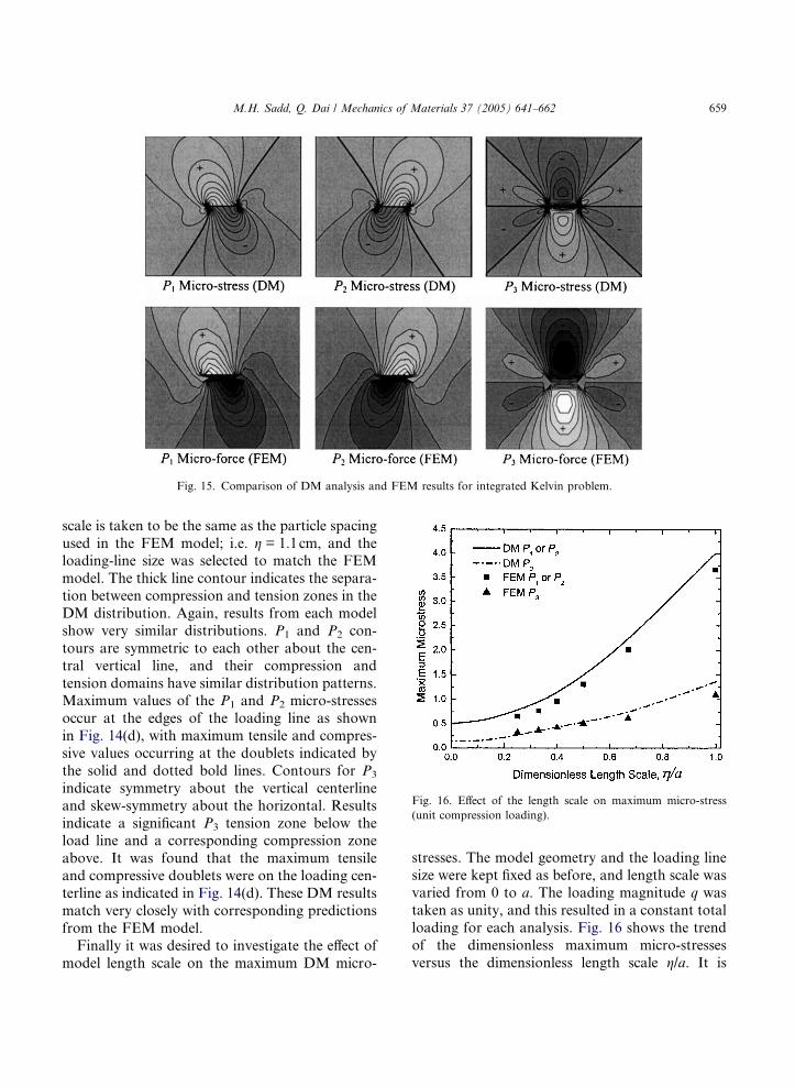
scale is taken to be the same as the particle spacing
used in the FEM model; i.e. g = 1.1cm, and theloading-line size was selected to match the FEM
model. The thick line contour indicates the separa-
tion between compression and tension zones in the
DM distribution. Again, results from each model
show very similar distributions. P1 and P2 con-
tours are symmetric to each other about the cen-
tral vertical line, and their compression and
tension domains have similar distribution patterns.Maximum values of the P1 and P2 micro-stresses
occur at the edges of the loading line as shown
in Fig. 14(d), with maximum tensile and compres-
sive values occurring at the doublets indicated by
the solid and dotted bold lines. Contours for P3
indicate symmetry about the vertical centerline
and skew-symmetry about the horizontal. Results
indicate a significant P3 tension zone below theload line and a corresponding compression zone
above. It was found that the maximum tensile
and compressive doublets were on the loading cen-
terline as indicated in Fig. 14(d). These DM results
match very closely with corresponding predictions
from the FEM model.
Finally it was desired to investigate the effect of
model length scale on the maximum DM micro-
stresses. The model geometry and the loading line
size were kept fixed as before, and length scale was
varied from 0 to a. The loading magnitude q was
taken as unity, and this resulted in a constant total
loading for each analysis. Fig. 16 shows the trend
of the dimensionless maximum micro-stresses
versus the dimensionless length scale g/a. It is
Fig. 16. Effect of the length scale on maximum micro-stress
(unit compression loading).
Fig. 15. Comparison of DM analysis and FEM results for integrated Kelvin problem.
M.H. Sadd, Q. Dai / Mechanics of Materials 37 (2005) 641–662 659
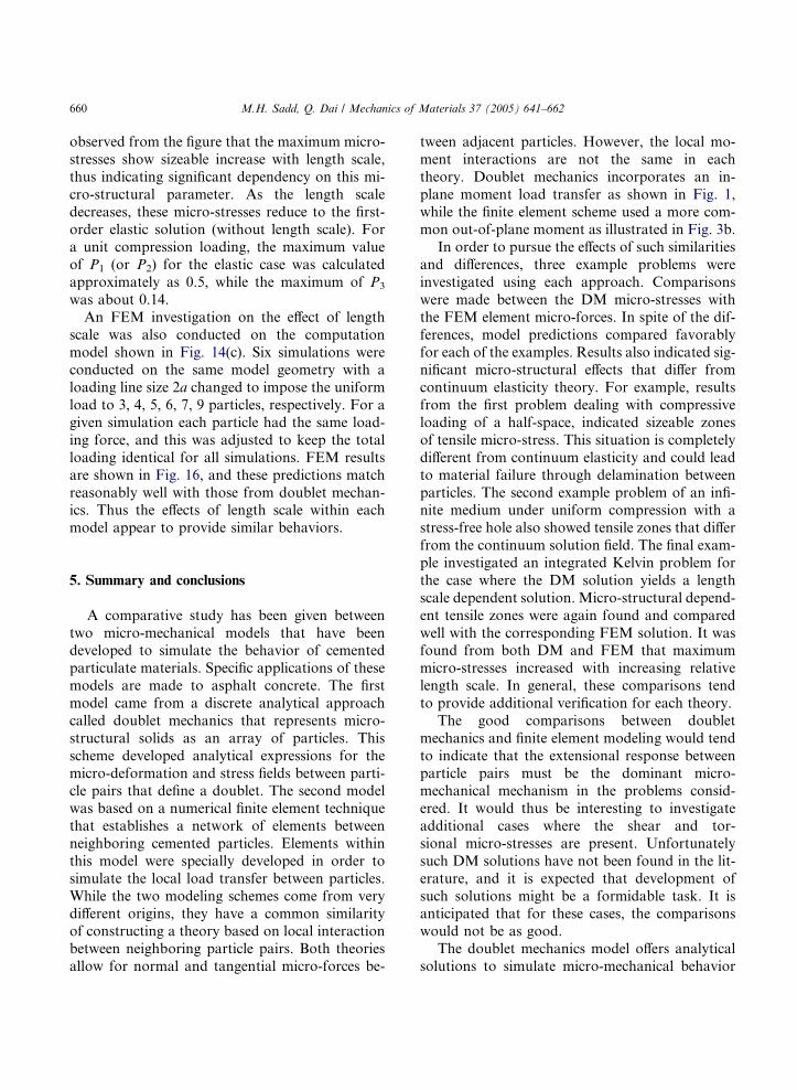
observed from the figure that the maximum micro-
stresses show sizeable increase with length scale,
thus indicating significant dependency on this mi-
cro-structural parameter. As the length scale
decreases, these micro-stresses reduce to the first-order elastic solution (without length scale). For
a unit compression loading, the maximum value
of P1 (or P2) for the elastic case was calculated
approximately as 0.5, while the maximum of P3
was about 0.14.
An FEM investigation on the effect of length
scale was also conducted on the computation
model shown in Fig. 14(c). Six simulations wereconducted on the same model geometry with a
loading line size 2a changed to impose the uniform
load to 3, 4, 5, 6, 7, 9 particles, respectively. For a
given simulation each particle had the same load-
ing force, and this was adjusted to keep the total
loading identical for all simulations. FEM results
are shown in Fig. 16, and these predictions match
reasonably well with those from doublet mechan-ics. Thus the effects of length scale within each
model appear to provide similar behaviors.
5. Summary and conclusions
A comparative study has been given between
two micro-mechanical models that have beendeveloped to simulate the behavior of cemented
particulate materials. Specific applications of these
models are made to asphalt concrete. The first
model came from a discrete analytical approach
called doublet mechanics that represents micro-
structural solids as an array of particles. This
scheme developed analytical expressions for the
micro-deformation and stress fields between parti-cle pairs that define a doublet. The second model
was based on a numerical finite element technique
that establishes a network of elements between
neighboring cemented particles. Elements within
this model were specially developed in order to
simulate the local load transfer between particles.
While the two modeling schemes come from very
different origins, they have a common similarityof constructing a theory based on local interaction
between neighboring particle pairs. Both theories
allow for normal and tangential micro-forces be-
tween adjacent particles. However, the local mo-
ment interactions are not the same in each
theory. Doublet mechanics incorporates an in-
plane moment load transfer as shown in Fig. 1,
while the finite element scheme used a more com-mon out-of-plane moment as illustrated in Fig. 3b.
In order to pursue the effects of such similarities
and differences, three example problems were
investigated using each approach. Comparisons
were made between the DM micro-stresses with
the FEM element micro-forces. In spite of the dif-
ferences, model predictions compared favorably
for each of the examples. Results also indicated sig-nificant micro-structural effects that differ from
continuum elasticity theory. For example, results
from the first problem dealing with compressive
loading of a half-space, indicated sizeable zones
of tensile micro-stress. This situation is completely
different from continuum elasticity and could lead
to material failure through delamination between
particles. The second example problem of an infi-nite medium under uniform compression with a
stress-free hole also showed tensile zones that differ
from the continuum solution field. The final exam-
ple investigated an integrated Kelvin problem for
the case where the DM solution yields a length
scale dependent solution. Micro-structural depend-
ent tensile zones were again found and compared
well with the corresponding FEM solution. It wasfound from both DM and FEM that maximum
micro-stresses increased with increasing relative
length scale. In general, these comparisons tend
to provide additional verification for each theory.
The good comparisons between doublet
mechanics and finite element modeling would tend
to indicate that the extensional response between
particle pairs must be the dominant micro-mechanical mechanism in the problems consid-
ered. It would thus be interesting to investigate
additional cases where the shear and tor-
sional micro-stresses are present. Unfortunately
such DM solutions have not been found in the lit-
erature, and it is expected that development of
such solutions might be a formidable task. It is
anticipated that for these cases, the comparisonswould not be as good.
The doublet mechanics model offers analytical
solutions to simulate micro-mechanical behavior
660 M.H. Sadd, Q. Dai / Mechanics of Materials 37 (2005) 641–662

of particular mechanics problems. However, for
more realistic problems involving irregular particle
sizes and packing geometries, it is unlikely that
such analytical DM solutions can be found. Of
course the finite element model can be used forsuch problems, and would therefore be the recom-
mended approach.
The presented comparisons have been limited to
only the elastic response. However, our finite ele-
ment model has incorporated damage mechanics
concepts in order to simulate inelastic and failure
of cemented particulate materials (Sadd et al.,
2004a,b). Likewise, doublet mechanics theory hasalso been extended to describe inelastic behavior,
and some specific failure criteria have been devel-
oped (Ferrari and Granik, 1995). Thus compari-
sons of the inelastic predictions between the two
theories appear to be workable and would be an
interesting future study.
Since most real particulate materials are three-
dimensional in nature, two-dimensional modelingis always subject to concern. Two-dimensional
limitations on material micro-structure (fabric)
and on out-of-plane degrees of freedom will nor-
mally not capture all of the micro-mechanics in
the particulate system. The usual simple uniform
scaling through the thickness can only approxi-
mate the actual behavior. In regard to three-
dimensional modeling, the additional degrees offreedom will add considerable complexity to both
the doublet mechanics and micro-mechanical fi-
nite element models. It would be expected that
constructing three-dimensional DM solutions
would be very difficult. We have recently begun
research on a three-dimensional micro-finite ele-
ment modeling scheme. Within this new model
each particle is allowed to have 6 degrees of free-dom, and this generates a two-noded, micro-finite
element with 12 degrees of freedom. We hope to
report three-dimensional simulations in the near
future.
Acknowledgment
The authors would like to acknowledge support
from the Transportation Center at the University
of Rhode Island under Grants 01-64 and 02-86.
References
Bahia, H., Zhai, H., Bonnetti, K., Kose, S., 1999. Nonlinear
viscoelastic and fatigue properties of asphalt binders. J.
Assoc. Asphalt Paving Technol. 68, 1–34.
Bardenhagen, S., Trianfyllidis, N., 1994. Derivation of higher
order gradient continuum theories in 2,3-D non-linear
elasticity from periodic lattice models. J. Mech. Phys. Solids
42 (1), 111–139.
Bathurst, R.J., Rothenburg, L., 1988. Micromechanical aspects
of isotropic granular assemblies with linear contact interac-
tions. J. Appl. Mech. 55, 17–23.
Bazant, Z.P., Tabbara, M.R., Kazemi, Y., Pijaudier-Cabot, G.,
1990. Random particle simulation of damage and fracture
in particulate or fiber-reinforced composites. In: Damage
Mechanics in Engineering Materials. Trans. ASME, AMD
109.
Birgisson, B., Soranakom, C., Napier, J.A.L., Roque, R., 2002.
Simulation of the cracking behavior of asphalt mixtures
using random assemblies of displacement discontinuity
boundary elements. In: Proc. 15th ASCE Eng. Mech. Conf.,
Columbia Universtiy.
Budhu, M., Ramakrishnan, S., Frantziskonis, G., 1997.
Modeling of granular materials: a numerical model using
lattices. In: Chang, C.S., Misra, A., Liang, R.Y., Babic, M.
(Eds.), Mechanics of Deformation and Flow of Particulate
Materials, Proc. McNu Conf., Trans. ASCE, Northwestern
University.
Buttlar, W.G., You, Z., 2001. Discrete element modeling of
asphalt concrete: micro-fabric approach. TRR, No. 1757,
pp. 111–118.
Chang, C.S., Gao, J., 1995. Second-gradient constitutive theory
for granular material with random packing structure. Int. J.
Solids Struct. 32 (16), 2279–2293.
Chang, C.S., Liao, C.L., 1990. Constitutive relationship for
particular medium with the effect of particle rotation. Int. J.
Solids Struct. 26 (4), 437–453.
Chang, C.S., Ma, L., 1991. A micromechanical-base micro-
polar theory for deformation of granular solids. Int. J.
Solids Struct. 28 (1), 67–86.
Chang, C.S., Ma, L., 1992. Elastic material constants for
isotropic granular solids with particle rotation. Int. J. Solids
Struct. 29 (8), 1001–1018.
Chang, C.S., Wang, T.K., Sluys, L.J., van Mier, J.G.M., 2002.
Fracture modeling using a microstructural mechanics
approach-I. Theory and formulation. Eng. Fract. Mech.
69 (17), 1941–1958.
Chang, G.K., Meegoda, N.J., 1993. Simulation of the behavior
of asphalt concrete using discrete element method. In: Proc.
2nd Int. Conf. Discr. Element Meth., MIT, pp. 437–448.
Cowin, S.C., 1984. The stresses around a hole in a linear elastic
material with voids. Quart. J. Mech. Appl. Math. 37, 441–
465.
Cowin, S.C., Nunziato, J.W., 1983. Linear elastic materials with
voids. J. Elast. 13, 125–147.
Dvorkin, J., Nur, A., Yin, H., 1994. Effective properties of
cemented granular materials. Mech. Mater. 18, 351–366.
M.H. Sadd, Q. Dai / Mechanics of Materials 37 (2005) 641–662 661

Eringen, A.C., 1968. Theory of micro-polar elasticity. In:
Liebowitz, H. (Ed.), Fracture—An Advanced Treatise, vol.
II. Academic Press, pp. 621–693.
Eringen, A.C., 1999. Microcontinuum Field Theories I. Foun-
dations and Solids. Springer.
Ferrari, M., Granik, V.T., 1995. Ultimate criteria for materials
with different properties in biaxial tension and compression:
a micromechanical approach. Matls. Sci. Eng. A 202,
84–93.
Ferrari, M., Granik, V.T., Imam, A., Nadeau, J., 1997.
Advances in Doublet Mechanics. Springer.
Granik, V.T., 1978. Microstructural mechanics of granular
media. Technique Report IM/MGU 78-241, Institute of
Mechanics of Moscow State University, in Russian.
Granik, V.T., Ferrari, M., 1993. Microstructural mechanics of
granular media. Mech. Mater. 15, 301–322.
Guddati, M.N., Feng, Z., Kim, Y.R., 2002. Towards a
micromechanics-based procedure to characterize fatigue
performance of asphalt concrete. In: Proc. 81st TRB Ann.
Meet., Washington, DC.
Konshi, J., Naruse, F., 1988. A note on fabric in terms of voids.
In: Satake, M., Jenkins, J.T. (Eds.), Micromechanics of
Granular Materials. Elsevier Science, Netherlands.
Kunin, I.A., 1983. Elastic Media with Microstructure II Three-
Dimensional Models. Springer-Verlag, Berlin.
Liao, C.L., Chang, C.S., 1992. A microstructural finite element
model for granular solids. Eng. Comp. 9, 267–276.
Mora, P., 1992. A lattice solid model for rock rheology and
tectonics. The Seismic Simulation Project Tech. Rep. 4, 3-
28, Institut de Physique du Globe, Paris.
Nemat-Nasser, S., Mehrabadi, M.M., 1983. Stress and fabric in
granular masses. In: Jenkins, J.T., Satake, M. (Eds.),
Mechanics of Granular Materials: New Models and Con-
stitutive Relations. Elsevier Science, Netherlands.
Ostoja-Starzewski, M., Wang, C., 1989. Linear elasticity of
planar delaunay networks: random field characterization of
effective moduli. Acta Mech. 80, 61–80.
Rothenburg, L., Bogobowicz, A., Haas, R., 1992. Microme-
chanical modeling of asphalt concrete in connection with
pavement rutting problems. Proceedings of 7th Interna-
tional Conference on Asphalt Pavements 1, 230–245.
Sadd, M.H., Dai, Q.L., 2001. Effect of microstructure on the
static and dynamic behavior of recycled asphalt material.
Report no. 536108, University of Rhode Island Transpor-
tation Center.
Sadd, M.H., Dai, Q.L., Parameswaran, V., Shukla, A., 2004a.
Microstructural simulation of asphalt materials: modeling
and experimental studies. J. Matl. Civil Eng. ASCE 16 (2),
107–115.
Sadd, M.H., Dai, Q.L., Parameswaran, V., Shukla, A., 2004b.
Simulation of asphalt materials using a finite element
micromechanical model and damage mechanics. J. Trans-
port. Res. Board 1832, 86–94.
Sadd, M.H., Gao, J.Y., 1997. The effect of particle damage on
wave propagation in granular materials. In: Chang, C.S.,
Misra, A., Liang, R.Y., Babic, M. (Eds.), Mechanics of
Deformation and Flow of Particulate Materials. In: Proc.
McNu Conf., Trans. ASCE, Northwestern University.
Sadd, M.H., Gao, J.Y., 1998. Contact micromechanics mode-
ling of the acoustic behavior of cemented particulate marine
sediments. In: Proc. 12th ASCE Eng. Mech. Conf., La Jolla,
CA.
Sadd, M.H., Qiu, L., Boardman, W., Shukla, A., 1992.
Modeling wave propagation in granular materials using
elastic networks. Intl. J. Rock Mech. Mining Sci. 29, 161–
170.
Sepehr, K., Harvey, O.J., Yue, Z.Q., El Husswin, H.M., 1994.
Finite element modeling of asphalt concrete microstructure.
In: Proc. 3rd Int. Conf. Comput. Aided Asses. Contr.
Localized Damage, Udine, Italy.
Soares, J.B., Colares de Freitas, F.A., Allen, D.H., 2003. Crack
modeling of asphaltic mixtures considering heterogeneity of
the material. In: Proc. 82nd TRB Meeting, Washington,
DC.
Stankowski, T., 1990. Numerical Simulation of Progressive
Failure in Particle Composites. Ph.D. Thesis, Univserity of
Colorado.
Trent, B.C., Margolin, L.G., 1994. Modeling fracture in
cemented granular materials. In: Fract. Mech. Appl. Geo-
tech. Eng. ASCE Pub., Proc. ASCE Nat. Convent., Atlanta.
Ullidtz, P., 2001. A study of failure in cohesive particulate
media using the discrete element method. In: Proc. 80th
TRB Meeting, Washington, DC.
Wang, L.B., Myers, L.A., Mohammad, L.N., Fu, Y.R., 2003. A
micromechanics study of top–down cracking. Proc. 81st
TRB Ann. Meet., Washington, DC.
662 M.H. Sadd, Q. Dai / Mechanics of Materials 37 (2005) 641–662