a cover ver 66 - custom cmm machines · cmm characteristics ... working with toolbars ... machine...
TRANSCRIPT
GeometUser Guide
Version 6.66June 2006
Covering:
Geomet 101, Geomet 101+, Geomet 301
Helmel Engineering Products, Inc6520 Lockport Road
Niagara Falls, NY 14305(716) 297-8644
(716) 297-9405 fax
www.helmel.comwww.geomet-cmm-software.com

Helmel Engineering Products, Inc. Geomet Training Handbookwww.helmel.com www.geomet-cmm-software.com
GeometUniversal CMM Software
Version 6.66December 2005
Covering:
Geomet 101, Geomet 101+, Geomet 301
ByEdward R. Yaris
Software Development Manager
Helmel Engineering Products, Inc.6520 Lockport Road
Niagara Falls, NY 14305(716) 297-8644
(716) 297-9405 fax
www.helmel.comwww.geomet-cmm-software.com

Helmel Engineering Products, Inc. Geomet Training Handbookwww.helmel.com www.geomet-cmm-software.com
GeometUniversal CMM Software
Information contained within this document issubject to change without notice. No part of thisdocument may be reproduced or transmitted inany form or by any means, electronic ormechanical, for any purpose, without writtenauthorization from Helmel EngineeringProducts, Inc.
This document contains trade secret subjectmatter of Helmel Engineering Products, Inc. andits receipt or possession does not convey anyright to reproduce, disclose its contents or tomanufacture, use or sell anything it maydescribe. Reproduction, disclosure or usewithout specific written authorization of HelmelEngineering Products, Inc. is strictly forbidden.
©Helmel Engineering Products, Inc.
Geomet®, Microstar™, CheckMaster™, aretrademark of Helmel Engineering Products, Inc.
Windows™ is a trademark of Microsoft Corp.
Helmel Engineering Products, Inc.6520 Lockport RoadNiagara Falls, NY 14305(716) 297-8644(716) 297-9405 fax
www.helmel.comwww.geomet-cmm-software.com
Contents
Helmel Engineering Products, Inc. Geomet Training Handbookwww.helmel.com www.geomet-cmm-software.com
Chapter 1 - GeometGeomet Program LevelsGeomet OptionsGeomet Comparison Chart
Chapter 2 – Table of Contents
Geomet Installation Guide – Introduction ..........................................2.2Changes to the Protection Device .................................................2.2
Geomet Installation Program Summary..............................................2.3Microsoft Direct X........................................................................2.3Drivers and System Support Files ................................................2.3
Installing Geomet – step-by-step Guide .............................................2.4Installing the Crypkey License Driver..........................................2.7Authorizing Geomet Software ......................................................2.8
Geomet System Options ...................................................................2.10Enhanced Features ......................................................................2.10Tolerance.....................................................................................2.13Probes and Sensors .....................................................................2.14File Locations .............................................................................2.15Report States ...............................................................................2.17Feature Characteristics................................................................2.18CMM Characteristics ..................................................................2.19Report Configuration ..................................................................2.21Colors..........................................................................................2.24Form Control...............................................................................2.25SPC Formats ...............................................................................2.26Tolerance Codes..........................................................................2.27Graphic Controls.........................................................................2.28
CMM Scale Compensation ...............................................................2.30Linear Compensation ..................................................................2.30Non-Linear Compensation..........................................................2.34
Geomet Toolbar Control ...................................................................2.36Interface Data Strip .....................................................................2.36
Working with Toolbars .....................................................................2.37
Geomet Toolbar Tables.....................................................................2.38
Contents
Helmel Engineering Products, Inc. Geomet Training Handbookwww.helmel.com www.geomet-cmm-software.com
Chapter 3 – Stylus Management
Stylus Manager .................................................................................. 3-2Probe Qualification Process......................................................... 3-2Stylus Manager Sub Menus ......................................................... 3-2Deleting Stylus............................................................................. 3-3Remove Pre-Qualified Stylus ...................................................... 3-6Duplicate a Stylus ........................................................................ 3-7Labeling a Stylus ......................................................................... 3-8
Qualifying a Ball Stylus..................................................................... 3-9
Qualifying Ball Styli in Multiple Positions ..................................... 3-10Note on Reference Sphere Location .......................................... 3-10
Entering a Known Probe Diameter .................................................. 3-11
Stylus Tip Relationships .................................................................. 3-12
Qualifying with a Motorized Probe Head........................................ 3-13
Qualifying with a Stylus Change Rack............................................ 3-15
Qualifying a Motorized Probe Head and Stylus Change Rack........ 3-18
Stylus Database Manager................................................................. 3-19Create a new Stylus Database .................................................... 3-20Import a Stylus Database ........................................................... 3-20Delete a Stylus Database Listing ............................................... 3-21Set active a Stylus Database ...................................................... 3-21Loading a Part Program ............................................................. 3-22
Renishaw SCR200/MCR 20 Stylus Rack Setup.............................. 3-24
Renishaw SCR200/MCR20 Maintenance Operations ..................... 3-31
Stylus Database Edit Control ........................................................... 3-35
Chapter 4 – Feature Measurement
Basic FeaturesPoint ................................................................................................... 4-2
1D Point ....................................................................................... 4-3Auto Direction Sensing and 1D Points ........................................ 4-42D Point ....................................................................................... 4-5Inside Radial / Outside Radial 2D Point ...................................... 4-6
Contents
Helmel Engineering Products, Inc. Geomet Training Handbookwww.helmel.com www.geomet-cmm-software.com
3D Point ....................................................................................... 4-7Inside Radial / Outside Radial 3D Point ...................................... 4-7Vector Point ................................................................................. 4-8Understanding Vector Points ....................................................... 4-9Vector Point Technical Discussion............................................ 4-11Vector Point Report Format....................................................... 4-12Vector Point, XYZ/IJK Known ................................................. 4-13Vector Point Unknown Data...................................................... 4-16Vector Point IJK Known............................................................ 4-18Vector Point XYZ Known ......................................................... 4-19Vector Point Import File ............................................................ 4-21
Line .................................................................................................. 4-34
Circle................................................................................................ 4-37
Plane................................................................................................. 4-39Upper / Lower Boundary Plane ................................................. 4-41
Sphere .............................................................................................. 4-43
Cylinder ........................................................................................... 4-44
Cone ................................................................................................. 4-46Cone Offset ................................................................................ 4-47Cone Diameter ........................................................................... 4-48Cone Drop Ball Test .................................................................. 4-49
Macro Features4 Point Intersect ......................................................................... 4-50Slot/Web .................................................................................... 4-51Oval Slot .................................................................................... 4-52
Feature Averaging............................................................................ 4-54
Chapter 5 – Coordinate Systems
Understanding Coordinate Systems................................................... 5-3Machine Coordinate System – MCS............................................ 5-3Part Coordinate System – PCS .................................................... 5-3PCS Base Planes .......................................................................... 5-5PCS versus MCS.......................................................................... 5-5Fixture Coordinate System – FCS ............................................... 5-5Interim Coordinate System – ICS................................................ 5-6Clearance Coordinate Systems – CCS......................................... 5-6
Contents
Helmel Engineering Products, Inc. Geomet Training Handbookwww.helmel.com www.geomet-cmm-software.com
Wobble Coordinate System – WCS............................................. 5-6The PCS Setup Guide .................................................................. 5-7
Coordinate System Commands.......................................................... 5-8ICS⇒PCS .................................................................................... 5-8Orient ......................................................................................... 5-10Align .......................................................................................... 5-11Origin ......................................................................................... 5-12Offset Align ............................................................................... 5-13Editing an Offset Align.............................................................. 5-14Pivot Align................................................................................. 5-15Rotate ......................................................................................... 5-16Edit an Existing Rotation Value ................................................ 5-17Translate..................................................................................... 5-18Edit an Existing Translation Value ............................................ 5-19
PCS Program Examples................................................................... 5-20#1, Basic Alignment................................................................... 5-21#2, Plane-Line-Point .................................................................. 5-23#3, Quick PCS............................................................................ 5-25#4, Plane-Circle-Circle .............................................................. 5-27#5, Plane-Cylinder-Circle .......................................................... 5-29#6, Plane-Bisect Points-Circle ................................................... 5-31#7, Cylinder-Circle-Point........................................................... 5-33#8, Plane-Intersect Lines-Bisect Points-Circle .......................... 5-35#9, Offset Alignment ................................................................. 5-38#10, Pivot Alignment ................................................................. 5-39#11, Translate............................................................................. 5-40#12, Rotate ................................................................................. 5-41
Coordinate System Manager............................................................ 5-42Recalling a Part Coordinate System .......................................... 5-42Recalling the Machine Coordinate System................................ 5-42Recalling a Fixture Coordinate System ..................................... 5-42Recalling a Vector Drive System............................................... 5-43
Fixture Coordinate System Manager ............................................... 5-44Import and Convert Pre-Geomet v 6.66 FCS Definitions.......... 5-45Using the FCS Manager............................................................. 5-47Adding a new FCS to the database ............................................ 5-48Selecting a FCS Record ............................................................. 5-49Attach Step................................................................................. 5-49Updating..................................................................................... 5-49Deleting...................................................................................... 5-50Locking ...................................................................................... 5-50
Contents
Helmel Engineering Products, Inc. Geomet Training Handbookwww.helmel.com www.geomet-cmm-software.com
Details ........................................................................................ 5-50Delete All ................................................................................... 5-50
Clearance Coordinate Systems ........................................................ 5-51
Chapter 6 – Tolerance
Introduction to Tolerance................................................................... 6-2
Linear Tolerance Theory.................................................................... 6-3
Working with Geomet Tolerance Windows ...................................... 6-5
Working with True Position Tolerance Windows ............................. 6-7
Interpreting Linear Tolerance in Geomet .......................................... 6-8
True Position Tolerance Theory ........................................................ 6-9
Datum Bonus Tolerance .................................................................. 6-11
Process Control Tolerance ............................................................... 6-12
Out-of-Tolerance Flash Message..................................................... 6-15
Vector Point Features – Apply Tolerance using Profile Bands ....... 6-16
GeoTol – Form Tolerance................................................................ 6-17
Runout: Cylinder/Plane.................................................................... 6-18
Chapter 7 – Constructions
Constructions – Brief Overview ........................................................ 7-2Selecting Features ........................................................................ 7-2Implicit Selection ......................................................................... 7-2Targeted Highlighting.................................................................. 7-2Feature Selection Tool ................................................................. 7-2
Bisect ................................................................................................. 7-3
Intersect.............................................................................................. 7-4General Features – Single Point Solutions .................................. 7-4Circle / Circle............................................................................... 7-4Circle Line ................................................................................... 7-6
Contents
Helmel Engineering Products, Inc. Geomet Training Handbookwww.helmel.com www.geomet-cmm-software.com
Offset Features ................................................................................... 7-8Offset Point .................................................................................. 7-8Offset Line ................................................................................... 7-9Offset Plane................................................................................ 7-10
Angle................................................................................................ 7-11
Distance ........................................................................................... 7-12
Extended Distance ........................................................................... 7-13Reporting Format Control.......................................................... 7-13Circle / Circle............................................................................. 7-14Cylinder / Sphere ....................................................................... 7-163D Point / 3D Point.................................................................... 7-18
Boundary Planes .............................................................................. 7-19
Inscribed / Circumscribed Circle ..................................................... 7-20
Recall Feature .................................................................................. 7-21Recall Feature Tool.................................................................... 7-21On Demand Recall ..................................................................... 7-21
Recall PCS Base Components ......................................................... 7-22
Chapter 8 – Support Tools and Features
Understanding Auto Direction Sensing ............................................. 8-3Activate Auto Direction Sensing ................................................. 8-4
Program Header ................................................................................. 8-5Fixture Usage Data Fields............................................................ 8-6
Restart Program Header..................................................................... 8-7Rerun Step Selection, Manual and DCC CMMs ......................... 8-7
EZ Launch Menu System................................................................... 8-8Activating the EZ Launch Menu System..................................... 8-8Creating and Editing Cradle Definitions...................................... 8-8Cradle Definitions........................................................................ 8-9Editing Cradle Definitions ......................................................... 8-10Assign and FCS to a Cradle ....................................................... 8-12Assign Inspection Files to a Cradle ........................................... 8-13EZ Launch Polling System ........................................................ 8-15EZ Launch Operational Sequence ............................................. 8-18
Contents
Helmel Engineering Products, Inc. Geomet Training Handbookwww.helmel.com www.geomet-cmm-software.com
Feature Selection Tool ..................................................................... 8-19Using PCS Filters....................................................................... 8-19Display only Measured and Constructed Features..................... 8-20Column Sorting.......................................................................... 8-20Applying your Selections........................................................... 8-20Math Function............................................................................ 8-21Diameter Averaging................................................................... 8-22Stylus Size Updating using a Ring Gage ................................... 8-22DCC Option Menu..................................................................... 8-23Rerun Feature Selector – Manual CMMs .................................. 8-24
Text Features.................................................................................... 8-25Manual Step Text Entry ............................................................. 8-25Basic Text .................................................................................. 8-27User Prompt with Image Support .............................................. 8-28In-Line Text Entry ..................................................................... 8-29
Custom Ordered Reports ................................................................. 8-31
Concise Reports ............................................................................... 8-34
Report Control Center...................................................................... 8-36
Print Exception / SPC Tags.............................................................. 8-37
Report Offset.................................................................................... 8-41
Digital Readout ................................................................................ 8-42Standard DRO............................................................................ 8-42Full DRO.................................................................................... 8-44
In-Line Math Calculator .................................................................. 8-46
GeoPlus Library ............................................................................... 8-48
Inspection Program Editing Tools ................................................... 8-53Undo........................................................................................... 8-53Delete ......................................................................................... 8-53Delete Permanently.................................................................... 8-55Delete All After.......................................................................... 8-56Edit History Tool ....................................................................... 8-57Insert .......................................................................................... 8-59Move .......................................................................................... 8-60Copy and Append ...................................................................... 8-61Jump to Feature Number............................................................ 8-62
Contents
Helmel Engineering Products, Inc. Geomet Training Handbookwww.helmel.com www.geomet-cmm-software.com
Feature Properties ............................................................................ 8-63Single Feature Selection Submenu ............................................ 8-63Single Feature Property Tool ..................................................... 8-64Multiple Selected Features Submenu......................................... 8-65
Report Navigation Keys................................................................... 8-67
File Archive ..................................................................................... 8-68
Chapter 9 – Working with Motion Control
Introduction to Motion Control.......................................................... 9-2Point Type Definitions................................................................. 9-2Special Considerations when Teaching Motion .......................... 9-3
Motion Adjustment Tools .................................................................. 9-4
Feature Generators ............................................................................. 9-4
DCC Home Position .......................................................................... 9-5
DCC Variables ................................................................................... 9-6
Motion Control Ribbon...................................................................... 9-7
Motion Edit Tool ............................................................................... 9-8
One-Step Motion Edit ...................................................................... 9-15
Disable Motion on Features ............................................................. 9-17
Motion Map Test ............................................................................. 9-19
Chapter 10 – Offline Tools
Introduction...................................................................................... 10-2
Feature Generators – Common Tools and Controls ........................ 10-3
Offline IP Generator ........................................................................ 10-6
Circle Generator............................................................................. 10-11
Cylinder Generator......................................................................... 10-15
Line Generator ............................................................................... 10-20

Contents
Helmel Engineering Products, Inc. Geomet Training Handbookwww.helmel.com www.geomet-cmm-software.com
Plane Generator.............................................................................. 10-22
Point Generator .............................................................................. 10-31
Bolt Hole Generator....................................................................... 10-35
Chapter 11 – Reverse Engineering
Introduction...................................................................................... 11-2
Reverse Engineering for Surface Generation .................................. 11-2
Summary of Reverse Engineering Tools ......................................... 11-3
Choosing a Scan Method ................................................................. 11-4
Manual Free Scan ............................................................................ 11-5
GeoTracer ........................................................................................ 11-6
Line Auto Scan ................................................................................ 11-9
4 Point Boundary Surface Scan ..................................................... 11-11
Radial Boundary Surface Scan ...................................................... 11-16
Understanding the Data Cloud Structure ....................................... 11-17
Cardinal Spline .............................................................................. 11-18
Exporting ....................................................................................... 11-23
Technical Notes
Curved Surface Measurement with Vector Point .................... App 1 - 2
Multi-Point Feature and CMM Inherent Errors ....................... App 1 - 9


Chapter 1 – Geomet
Helmel Engineering Products, Inc. Geomet Training Handbookwww.helmel.com www.geomet-cmm-software.com
1-1
Geomet Version Comparison Chart
Geomet operates in three different levels designed to match your inspectionneeds. These levels are known as:
• Geomet Junior• Geomet 101• Geomet 301
Geomet Junior
Geomet Junior is the entry-level full 3D-inspection system of the Geomet series,yet it is packed with most of the functions needed for basic inspection. It favorsone touch access to all basic geometric elements in addition to a highly visible setof icons on the screen for intuitive measuring without extensive training. GeometJunior includes a powerful set of Part Coordinate System (PCS) generation toolsthat Geomet is famous for. You can customize Geomet Junior by adding theoptions; Direct Computer Control, Programming, Advanced PCS and GeoPlus.Geomet Junior is included with the purchase of all Helmel manual CoordinateMeasuring Machines.
Geomet 101
Geomet 101, our most popular package, offers great flexibility for inspectingparts in the lab or on the production floor. The graphical area on the right side ofthe display generates a pictorial representation of the measured features whichserves as a visual guide for part programs and as a link to the final inspectionresults. Program writing is done in the self-teach mode, editing is easy andefficient. Geomet 101 includes a full suite of reverse engineering tools. TheGeoPlus option expands Geomet 101 to include powerful features such as VectorPoint, customized tagging for printing and exporting and analytical tools forcircular features. Geomet 101 is designed for the production environment whereobtaining and tracking numerical solutions is preferred.
Geomet 301
Geomet 301, our most advanced system, offers the sophisticated user unbridledmeasuring power with the typical user friendliness of Geomet. It contains all thepower of Geomet 101, GeoPlus and a host of other analytical tools to review andmanipulate your part inspections. The time proven and inherent quality of theGeomet algorithms guarantee meaningful results when creating new and difficultrelationships out of measured features and PCS's. Geomet 301 offers an optionalexpansion package to unlock the power of surface point analysis against a CADmodel. This power allows the user to align the CAD model with the part to beinspected. Then capturing of data points can be calculated against the model toobtain position within a profile zone.
NOTE: Keep current with the latestchanges in Geomet by visiting:
www.geomet-cmm-software.com

Chapter 1 – Geomet
Helmel Engineering Products, Inc . Geomet Training Handbookwww.helmel.com www.geomet-cmm-software.com
1-2
Geomet Options
All levels of Geomet can be expanded to include advanced feature and hardwaresupport. Some options are universal and can be used by all levels of Geomet. Thefollowing chart details the options available to Geomet.
Geomet Option ChartGeometJunior Geomet 101 Geomet 301
1 Geomet Junior Plus X2 Direct Computer Control (DCC) X (1) X X3 GeoPlus X X4 Renishaw UCC Scanning Controller X X5 Renishaw Stylus Racks X (2) X (2)
6 Motorized Probe Support X (2) X (2)
7 LDI Line Laser Scanner X (2) X (2)
8 Gauss Meter X X X9 CAD Modeling X10 Apollo Low Force Touch Probe X X X11 Robotic I/O Interface X12 CNC Tool Offset Interface X
1 – DCC on Junior include Programming and Advanced PCS and Stylus options.2 – Requires either DCC or UCC option.
Geomet Junior Plus
Geomet Junior does not "cycle" a part program and allows one qualified stylusand one coordinate system, which can be redefined during inspections. Thisoption expands Junior to allow unlimited Coordinate Systems, unlimited StylusSupport, Advanced PCS and Tolerance tools and program cycling.
GeoPlus
This option is designed to expand Geomet 101 by adding many popular featureswithout having to upgrade to the next full version. With GeoPlus you have accessto circular profiles, planar profiles and program library support. Custom printoutsand ASCII exporting are handled through feature attribute tagging.
GeoPlus Expansion ModuleCircular Profile Graphical Circle ReportingPlanar Profile Graphical Planar ReportingVector Point Surface Vector PointsGeomet Gage R&R Link to Gage R&R External ProgramCustom Print Tags Attribute Selection for PrintingSPC ASCII Export Attribute Selection for ExportingFeature Offset Reporting Applying an Offset Value to ResultsLibrary Import / Export / Sharing Program StepsFast Start Menus On-Touch access to launching inspection ProgramsOut-of-Tolerance Notification On Screen notification when an Out-of-Tolerance condition exists.Geomet Gage R&R is a separate program that is linked to pass results with Geomet.
Chapter 1 – Geomet
Helmel Engineering Products, Inc. Geomet Training Handbookwww.helmel.com www.geomet-cmm-software.com
1-3
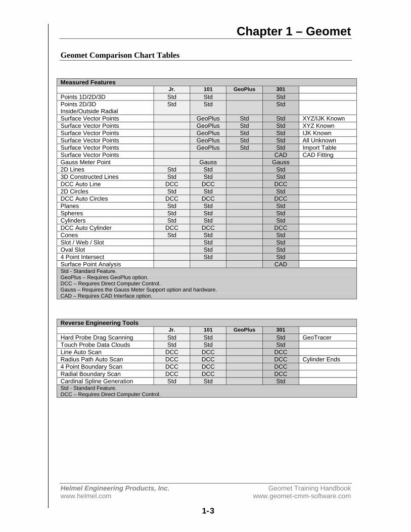
Geomet Comparison Chart Tables
Measured FeaturesJr. 101 GeoPlus 301
Points 1D/2D/3D Std Std StdPoints 2D/3DInside/Outside Radial
Std Std Std
Surface Vector Points GeoPlus Std Std XYZ/IJK KnownSurface Vector Points GeoPlus Std Std XYZ KnownSurface Vector Points GeoPlus Std Std IJK KnownSurface Vector Points GeoPlus Std Std All UnknownSurface Vector Points GeoPlus Std Std Import TableSurface Vector Points CAD CAD FittingGauss Meter Point Gauss Gauss2D Lines Std Std Std3D Constructed Lines Std Std StdDCC Auto Line DCC DCC DCC2D Circles Std Std StdDCC Auto Circles DCC DCC DCCPlanes Std Std StdSpheres Std Std StdCylinders Std Std StdDCC Auto Cylinder DCC DCC DCCCones Std Std StdSlot / Web / Slot Std StdOval Slot Std Std4 Point Intersect Std StdSurface Point Analysis CADStd - Standard Feature.GeoPlus – Requires GeoPlus option.DCC – Requires Direct Computer Control.Gauss – Requires the Gauss Meter Support option and hardware.CAD – Requires CAD Interface option.
Reverse Engineering ToolsJr. 101 GeoPlus 301
Hard Probe Drag Scanning Std Std Std GeoTracerTouch Probe Data Clouds Std Std StdLine Auto Scan DCC DCC DCCRadius Path Auto Scan DCC DCC DCC Cylinder Ends4 Point Boundary Scan DCC DCC DCCRadial Boundary Scan DCC DCC DCCCardinal Spline Generation Std Std StdStd - Standard Feature.DCC – Requires Direct Computer Control.
Chapter 1 – Geomet
Helmel Engineering Products, Inc . Geomet Training Handbookwww.helmel.com www.geomet-cmm-software.com
1-4
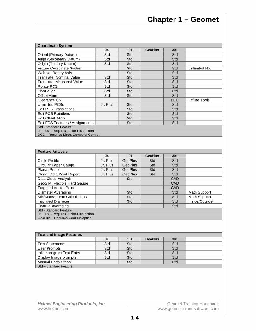
Coordinate SystemJr. 101 GeoPlus 301
Orient (Primary Datum) Std Std StdAlign (Secondary Datum) Std Std StdOrigin (Tertiary Datum) Std Std StdFixture Coordinate System Std Std Unlimited No.Wobble, Rotary Axis Std StdTranslate, Nominal Value Std Std StdTranslate, Measured Value Std Std StdRotate PCS Std Std StdPivot Align Std Std StdOffset Align Std Std StdClearance CS DCC Offline ToolsUnlimited PCSs Jr. Plus Std StdEdit PCS Translations Std StdEdit PCS Rotations Std StdEdit Offset Align Std StdEdit FCS Features / Assignments Std StdStd - Standard Feature.Jr. Plus – Requires Junior-Plus option.DCC – Requires Direct Computer Control.
Feature AnalysisJr. 101 GeoPlus 301
Circle Profile Jr. Plus GeoPlus Std StdCircular Paper Gauge Jr. Plus GeoPlus Std StdPlanar Profile Jr. Plus GeoPlus Std StdPlanar Data Point Report Jr. Plus GeoPlus Std StdData Cloud Analysis Std CADGeoSIM, Flexible Hard Gauge CADTargeted Vector Point CADDiameter Averaging Std Std Math SupportMin/Max/Spread Calculations Std Std Math SupportInscribed Diameter Std Std Inside/OutsideFeature Averaging StdStd - Standard Feature.Jr. Plus – Requires Junior-Plus option.GeoPlus – Requires GeoPlus option.
Text and Image FeaturesJr. 101 GeoPlus 301
Text Statements Std Std StdUser Prompts Std Std StdInline program Text Entry Std Std StdDisplay Image prompts Std Std StdManual Entry Steps Std StdStd – Standard Feature.
Chapter 1 – Geomet
Helmel Engineering Products, Inc. Geomet Training Handbookwww.helmel.com www.geomet-cmm-software.com
1-5
ConstructionsJr. 101 GeoPlus 301
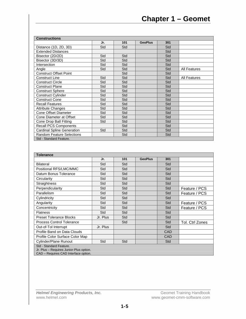
Distance (1D, 2D, 3D) Std Std StdExtended Distances StdBisector (2D/2D) Std Std StdBisector (3D/3D) Std Std StdIntersection Std Std StdAngle Std Std Std All FeaturesConstruct Offset Point Std StdConstruct Line Std Std Std All FeaturesConstruct Circle Std Std StdConstruct Plane Std Std StdConstruct Sphere Std Std StdConstruct Cylinder Std Std StdConstruct Cone Std Std StdRecall Features Std Std StdAttribute Changes Std Std StdCone Offset Diameter Std Std StdCone Diameter at Offset Std Std StdCone Drop Ball Fitting Std Std StdRecall PCS Components Std StdCardinal Spline Generation Std Std StdRandom Feature Selections Std StdStd - Standard Feature.
ToleranceJr. 101 GeoPlus 301
Bilateral Std Std StdPositional RFS/LMC/MMC Std Std StdDatum Bonus Tolerance Std Std StdCircularity Std Std StdStraightness Std Std StdPerpendicularity Std Std Std Feature / PCSParallelism Std Std Std Feature / PCSCylindricity Std Std StdAngularity Std Std Std Feature / PCSConcentricity Std Std Std Feature / PCSFlatness Std Std StdPreset Tolerance Blocks Jr. Plus Std StdProcess Control Tolerance Std Std Tol. Ctrl ZonesOut-of-Tol Interrupt Jr. Plus StdProfile Band on Data Clouds CADProfile Color Surface Color Map CADCylinder/Plane Runout Std Std StdStd - Standard Feature.Jr. Plus – Requires Junior-Plus option.CAD – Requires CAD Interface option.
Chapter 1 – Geomet
Helmel Engineering Products, Inc . Geomet Training Handbookwww.helmel.com www.geomet-cmm-software.com
1-6
Probes and SensorsJr. 101 GeoPlus 301
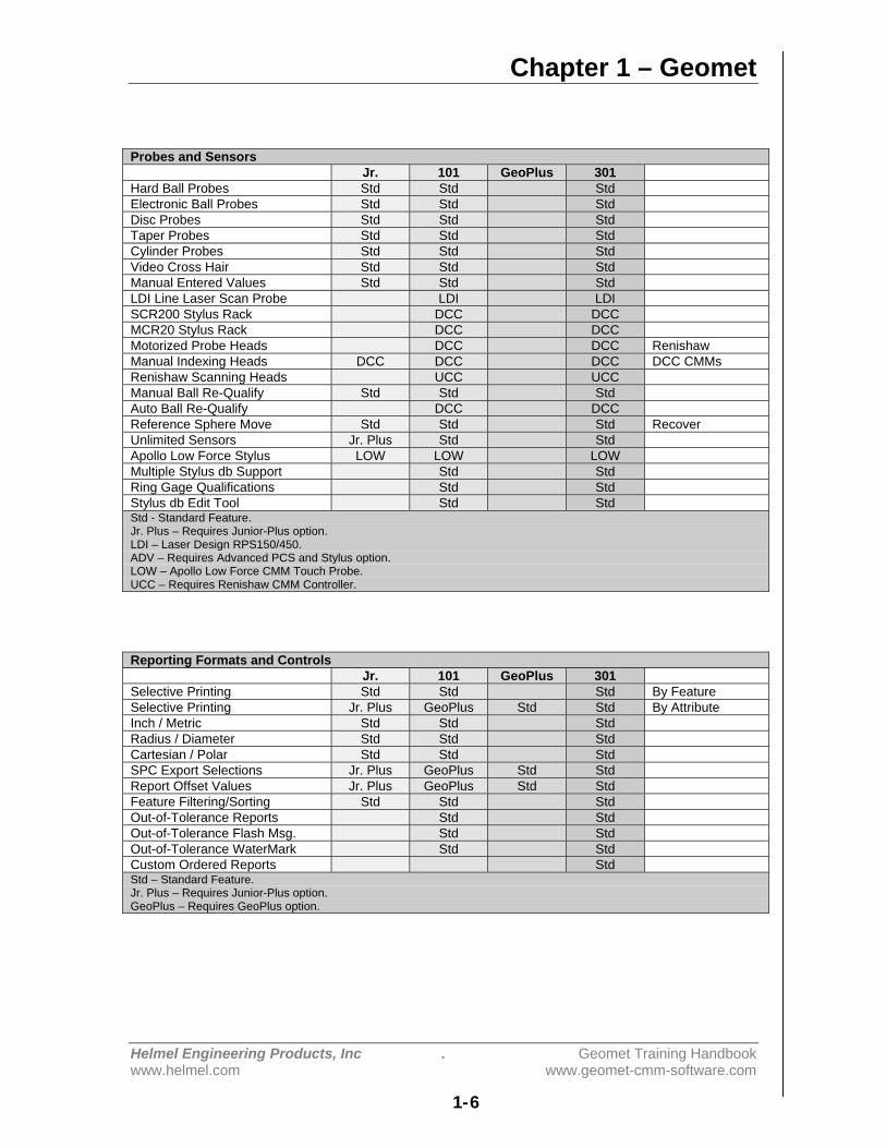
Hard Ball Probes Std Std StdElectronic Ball Probes Std Std StdDisc Probes Std Std StdTaper Probes Std Std StdCylinder Probes Std Std StdVideo Cross Hair Std Std StdManual Entered Values Std Std StdLDI Line Laser Scan Probe LDI LDISCR200 Stylus Rack DCC DCCMCR20 Stylus Rack DCC DCCMotorized Probe Heads DCC DCC RenishawManual Indexing Heads DCC DCC DCC DCC CMMsRenishaw Scanning Heads UCC UCCManual Ball Re-Qualify Std Std StdAuto Ball Re-Qualify DCC DCCReference Sphere Move Std Std Std RecoverUnlimited Sensors Jr. Plus Std StdApollo Low Force Stylus LOW LOW LOWMultiple Stylus db Support Std StdRing Gage Qualifications Std StdStylus db Edit Tool Std StdStd - Standard Feature.Jr. Plus – Requires Junior-Plus option.LDI – Laser Design RPS150/450.ADV – Requires Advanced PCS and Stylus option.LOW – Apollo Low Force CMM Touch Probe.UCC – Requires Renishaw CMM Controller.
Reporting Formats and ControlsJr. 101 GeoPlus 301
Selective Printing Std Std Std By FeatureSelective Printing Jr. Plus GeoPlus Std Std By AttributeInch / Metric Std Std StdRadius / Diameter Std Std StdCartesian / Polar Std Std StdSPC Export Selections Jr. Plus GeoPlus Std StdReport Offset Values Jr. Plus GeoPlus Std StdFeature Filtering/Sorting Std Std StdOut-of-Tolerance Reports Std StdOut-of-Tolerance Flash Msg. Std StdOut-of-Tolerance WaterMark Std StdCustom Ordered Reports StdStd – Standard Feature.Jr. Plus – Requires Junior-Plus option.GeoPlus – Requires GeoPlus option.
Chapter 1 – Geomet
Helmel Engineering Products, Inc. Geomet Training Handbookwww.helmel.com www.geomet-cmm-software.com
1-7
Special FunctionsJr. 101 GeoPlus 301
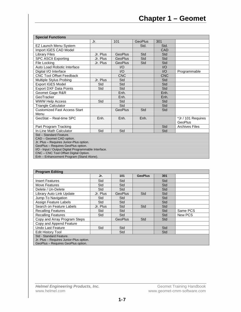
EZ Launch Menu System Std. Std.Import IGES CAD Model CADLibrary Files Jr. Plus GeoPlus Std StdSPC ASCII Exporting Jr. Plus GeoPlus Std StdFile Locking Jr. Plus GeoPlus Std StdAuto Load Robotic Interface I/O I/ODigital I/O Interface I/O I/O ProgrammableCNC Tool Offset Feedback CNC CNCMultiple Stylus Probing Jr. Plus Std StdExport IGES Model Std Std StdExport DXF Data Points Std Std StdGeomet Gage R&R Enh. Enh.GeoTracker Enh. Enh.WWW Help Access Std Std StdTriangle Calculator Std StdCustomized Fast Access StartMenu
GeoPlus Std Std
GeoStat – Real-time SPC Enh. Enh. Enh. *Jr / 101 RequiresGeoPlus
Part Program Tracking Std Archives FilesIn-Line Math Calculator Std Std StdStd – Standard Feature.CAD – Geomet CAD option.Jr. Plus – Requires Junior-Plus option.GeoPlus – Requires GeoPlus option.I/O - Input / Output Digital Programmable Interface.CNC – CNC Tool Offset Digital Option.Enh – Enhancement Program (Stand Alone).
Program EditingJr. 101 GeoPlus 301
Insert Features Std Std StdMove Features Std Std StdDelete / Un-Delete Std Std StdLibrary Auto Link Update Jr. Plus GeoPlus Std StdJump-To Navigation Std Std StdAssign Feature Labels Std Std StdSearch on Feature Labels Jr. Plus Std Std StdRecalling Features Std Std Std Same PCSRecalling Features Std Std Std New PCSCopy and Array Program Steps GeoPlus Std StdCopy and Append FeatureUndo Last Feature Std Std StdEdit History Tool Std StdStd - Standard Feature.Jr. Plus – Requires Junior-Plus option.GeoPlus – Requires GeoPlus option.

Chapter 1 – Geomet
Helmel Engineering Products, Inc . Geomet Training Handbookwww.helmel.com www.geomet-cmm-software.com
1-8
Program Editing – Direct Computer Control ToolsJr. 101 GeoPlus 301
Optimize DCC Circles Std StdOffline DCC Circles Std StdOffline DCC Cylinders Std StdDCC Clearance Planes Std StdHigh Accuracy Motion Targeting Std StdHigh Accuracy FeatureAveraging
Std Std Test & Re-Run
Re-Teach Motion Path Std Std StdSingle Step Motion Std Std StdMotion Parameter Control Std Std StdInsert / Teach Motion Path Std Std StdOffset and Copy Motion Path Std Std StdJoystick in Part Coordinates Std Std StdMP Capture on Specified Targets StdMotion Path Test Std StdFeature Specific Motion Disable Std Std StdOne-Step Motion Edit Std StdReRun Program Steps Std StdStd – Standard Feature.
Chapter 2 – System Setup
Helmel Engineering Products, Inc. Geomet Training Handbookwww.helmel.com www.geomet-cmm-software.com
2-1
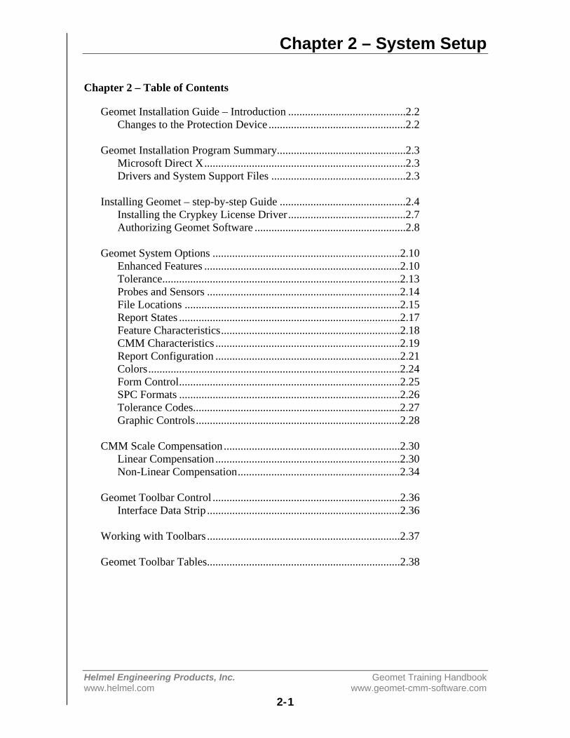
Chapter 2 – Table of Contents
Geomet Installation Guide – Introduction ..........................................2.2Changes to the Protection Device .................................................2.2
Geomet Installation Program Summary..............................................2.3Microsoft Direct X........................................................................2.3Drivers and System Support Files ................................................2.3
Installing Geomet – step-by-step Guide .............................................2.4Installing the Crypkey License Driver..........................................2.7Authorizing Geomet Software ......................................................2.8
Geomet System Options ...................................................................2.10Enhanced Features ......................................................................2.10Tolerance.....................................................................................2.13Probes and Sensors .....................................................................2.14File Locations .............................................................................2.15Report States ...............................................................................2.17Feature Characteristics................................................................2.18CMM Characteristics ..................................................................2.19Report Configuration ..................................................................2.21Colors..........................................................................................2.24Form Control...............................................................................2.25SPC Formats ...............................................................................2.26Tolerance Codes..........................................................................2.27Graphic Controls.........................................................................2.28
CMM Scale Compensation ...............................................................2.30Linear Compensation ..................................................................2.30Non-Linear Compensation..........................................................2.34
Geomet Toolbar Control ...................................................................2.36Interface Data Strip .....................................................................2.36
Working with Toolbars .....................................................................2.37
Geomet Toolbar Tables.....................................................................2.38
Chapter 2 – System Setup
Helmel Engineering Products, Inc. Geomet Training Handbookwww.helmel.com www.geomet-cmm-software.com
2-2
Geomet Installation Guide - Introduction
Summary of basic steps
1. Uninstall the old Geomet.2. Install the new Geomet.3. Install the Crypkey license driver.4. Run Geomet and Obtain Site Code.5. Contact Helmel Engineering for the GeoSecure Code6. Enter the GeoSecure Code to activate your Geomet products.
IMPORTANT: Changes to the Protection Device
With the introduction of Geomet version 6.66, the new protection scheme for theGeomet family of software incorporates the Crypkey software license system.Earlier versions of Geomet required the use of a hardware “dongle” that pluggedinto the parallel port. This protection dongle will only be required if you are usingGeoCAD. Once Geomet version 6.66 is installed and running, the hardwaredongle should be returned to Helmel.
The Crypkey software protection scheme utilizes information from the PC togenerate the Geomet authorization codes. The codes are unique to your computersystem, and cannot be used on another system. The system will run withWindows 98 SE and Windows 2000/XP. Windows 2000/XP systems need to havethe Crypkey license installed and running as a Windows service. On a Windows98 SE system, the protection device runs as a system driver, not a service.
Chapter 2 – System Setup
Helmel Engineering Products, Inc. Geomet Training Handbookwww.helmel.com www.geomet-cmm-software.com
2-3
The Geomet Installation Program - Summary
The Geomet installation program will install Geomet, GeoClean, GeoStat, andGage R&R. When Geomet has been authorized, your GeoStat and Gage R&R willalso be authorized if those options have been purchased. Both GeoStat and GageR&R can be authorized without enabling Geomet, for stand alone cases in whicha PC separate from the CMM is to be used for data analysis.
Microsoft Direct X
Geomet uses Microsoft Direct X 9.0c for sound and image support. Theinstallation process will verify and install version 9.0c if required.
Additional Drivers and System Support Files
Driver and System Support files (*.sys, *.inf and *.ocx) for all Geomet operationsare installed. Changes have been made to the CMM interface drivers. Previouslythere was an entry in the Windows Registry that no longer is required. The newCMM drivers are registered with the Windows System. The installation processwill guide you to setting up your interface.

Chapter 2 – System Setup
Helmel Engineering Products, Inc. Geomet Training Handbookwww.helmel.com www.geomet-cmm-software.com
2-4
Before Installing Geomet
Uninstall Previous Geomet Versions
Before you run the installation program, it is important that you uninstall allexisting Geomet related programs. This includes GeoStat and Gage R&R. Use theControl Panel tool provided in Windows to uninstall the Geomet software. In theexample below, we show the Control Panel on a Windows XP system.
Windows XP Control Panel
Locate the program Add or Remove Programs and start that application bydouble clicking. A listing of all programs for which Windows has uninstalloptions will be listed. Locate the Geomet listing, see figure 2, and select the<Remove> button.
Windows XP Control Panel
You will be asked to confirm that Geomet should be removed. Answer byaccepting <Yes> and Geomet and all associated program files will be removed.
The uninstall process does not remove any Windows registry settings, inspectionprograms, library pr stylus database files associated with Geomet. Therefore, theupdated Geomet will retain the preference settings previously active. Werecommend as a normal operating procedure that you always make a backup copyof your inspection part programs. If required, repeat the uninstall process forGeoStat and Gage R&R programs.

Chapter 2 – System Setup
Helmel Engineering Products, Inc. Geomet Training Handbookwww.helmel.com www.geomet-cmm-software.com
2-5
Installing Geomet – Step-by-Step Guide
To install Geomet, place the CD in your system’s drive. This CD does not containan auto run option and you should open and view the contents of the CD withWindows Explorer or similar method. Please ensure all programs are closedbefore performing the installation. On the root directory, there are several foldersand text files.
Geomet Installation CD Root Directory
Step 1 – Readme.pdf
Before you begin the installation please take a quick review of the Readme.pdflatest instructions for any changes to the installation process not covered here.Should your system not have Adobe Acrobat Reader installed, please see thesection on installing the Acrobat Reader later in this document.
To start the Geomet installation, double click on the file setup.exe. The setuproutine will launch and guide you through the required steps.
Step 2 – Welcome to the Installer
This first step is the welcome screen for the installer, press <Next> to proceed.
Step 3 – License Agreement
This step requires that you have read and agreed to the terms and conditions inregard to using Geomet.
Step 4 – Customer Information
Complete the required fields as appropriate.
Step 5 – CMM Interface
Choose the CMM Interface as noted on the Geomet Software Security Codesheet.

Chapter 2 – System Setup
Helmel Engineering Products, Inc. Geomet Training Handbookwww.helmel.com www.geomet-cmm-software.com
2-6
Step 6 – Custom Setup
Press the <Next> button to accept the defaults. By default all help files and driverfiles are installed. You can choose to remove these files from the installation.
Step 7 – Ready to Install
The final step, when accepted by pressing the <Install> button, will begin theinstallation of Geomet to your system. Installation also installs the files necessaryfor the uninstall process.
Once completed, the installer will notify you of the success of the installationprocess. Should any errors occur, you will be notified. The most common errornoted has been leaving Geomet active (open) while attempting to upgrade. Thiswill cause an error and the installation process will fail.
Chapter 2 – System Setup
Helmel Engineering Products, Inc. Geomet Training Handbookwww.helmel.com www.geomet-cmm-software.com
2-7
Installing the Crypkey License Driver
Before Geomet version 6.66 can be authorized, the Crypkey license service needsto be installed and running on the computer. Open GeoClean through theWindows⇒Start menu and locating:
[All Programs⇒HelmelEnginering⇒GeoClean].
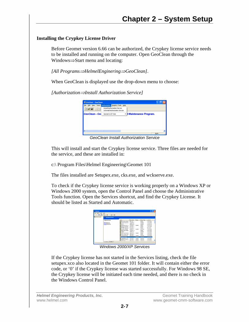
When GeoClean is displayed use the drop-down menu to choose:
[Authorization⇒Install Authorization Service]
GeoClean Install Authorization Service
This will install and start the Crypkey license service. Three files are needed forthe service, and these are installed in:
c:\ Program Files\Helmel Engineering\Geomet 101
The files installed are Setupex.exe, cks.exe, and wckserve.exe.
To check if the Crypkey license service is working properly on a Windows XP orWindows 2000 system, open the Control Panel and choose the AdministrativeTools function. Open the Services shortcut, and find the Crypkey License. Itshould be listed as Started and Automatic.
Windows 2000/XP Services
If the Crypkey license has not started in the Services listing, check the filesetupex.xco also located in the Geomet 101 folder. It will contain either the errorcode, or ‘0’ if the Crypkey license was started successfully. For Windows 98 SE,the Crypkey license will be initiated each time needed, and there is no check inthe Windows Control Panel.
Chapter 2 – System Setup
Helmel Engineering Products, Inc. Geomet Training Handbookwww.helmel.com www.geomet-cmm-software.com
2-8
Authorizing the Geomet Software
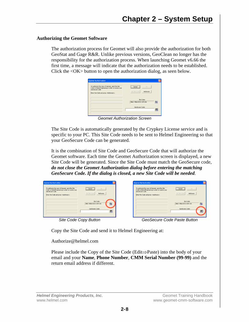
The authorization process for Geomet will also provide the authorization for bothGeoStat and Gage R&R. Unlike previous versions, GeoClean no longer has theresponsibility for the authorization process. When launching Geomet v6.66 thefirst time, a message will indicate that the authorization needs to be established.Click the <OK> button to open the authorization dialog, as seen below.
Geomet Authorization Screen
The Site Code is automatically generated by the Crypkey License service and isspecific to your PC. This Site Code needs to be sent to Helmel Engineering so thatyour GeoSecure Code can be generated.
It is the combination of Site Code and GeoSecure Code that will authorize theGeomet software. Each time the Geomet Authorization screen is displayed, a newSite Code will be generated. Since the Site Code must match the GeoSecure code,do not close the Geomet Authorization dialog before entering the matchingGeoSecure Code. If the dialog is closed, a new Site Code will be needed.
Site Code Copy Button GeoSecure Code Paste Button
Copy the Site Code and send it to Helmel Engineering at:
Please include the Copy of the Site Code (Edit⇒Paste) into the body of youremail and your Name, Phone Number, CMM Serial Number (99-99) and thereturn email address if different.
Chapter 2 – System Setup
Helmel Engineering Products, Inc. Geomet Training Handbookwww.helmel.com www.geomet-cmm-software.com
2-9
We will contact you as soon as possible with a GeoSecure Code. When youreceive the return email, highlight the supplied GeoSecure Code and copy(Edit⇒Copy) and Paste it into your Geomet Authorization dialog. Press<Authorize> after the GeoSecure code has been entered.
If your email service is not on the same computer as the Geomet system, copy theGeoSecure Code and enter it manually.
Once Geomet has been authorized, click the <OK> button to continue startingGeomet. To check the enabled options while Geomet is running, press Ctrl-Alt-Ufrom the main screen of Geomet to show the Geomet Authorization dialog.Should you want to change your options, you can generate a new Site Code fromthis dialog, which can be sent to Helmel Engineering in order to change theenabled levels and options.
If the authorization of Geomet included the options for GeoStat and Gage R&R,these programs can be opened at any time. Otherwise when attempting to open theprogram, an authorization screen similar to Geomet’s will be displayed, requiringa GeoSecure code to enable the program.
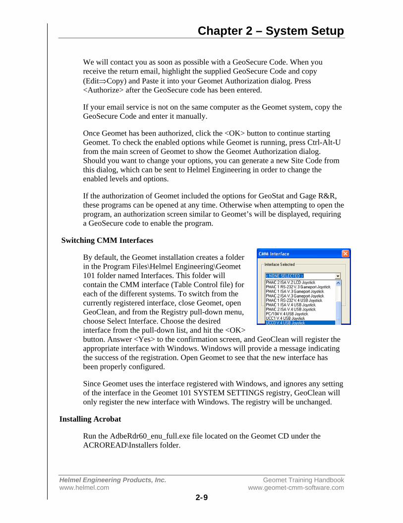
Switching CMM Interfaces
By default, the Geomet installation creates a folderin the Program Files\Helmel Engineering\Geomet101 folder named Interfaces. This folder willcontain the CMM interface (Table Control file) foreach of the different systems. To switch from thecurrently registered interface, close Geomet, openGeoClean, and from the Registry pull-down menu,choose Select Interface. Choose the desiredinterface from the pull-down list, and hit the <OK>button. Answer <Yes> to the confirmation screen, and GeoClean will register theappropriate interface with Windows. Windows will provide a message indicatingthe success of the registration. Open Geomet to see that the new interface hasbeen properly configured.
Since Geomet uses the interface registered with Windows, and ignores any settingof the interface in the Geomet 101 SYSTEM SETTINGS registry, GeoClean willonly register the new interface with Windows. The registry will be unchanged.
Installing Acrobat
Run the AdbeRdr60_enu_full.exe file located on the Geomet CD under theACROREAD\Installers folder.
Chapter 2 – System Setup
Helmel Engineering Products, Inc. Geomet Training Handbookwww.helmel.com www.geomet-cmm-software.com
2-10
Geomet System Options
Keyboard: F9
Menu: System ⇒ System Options
The Geomet system has many options and system characteristics that control thebehavior of the system. These include optional hardware, file locations, defaultfeatures setting to name a few.
The System Options tool provides access to many of these internal settings.
Enhanced Features
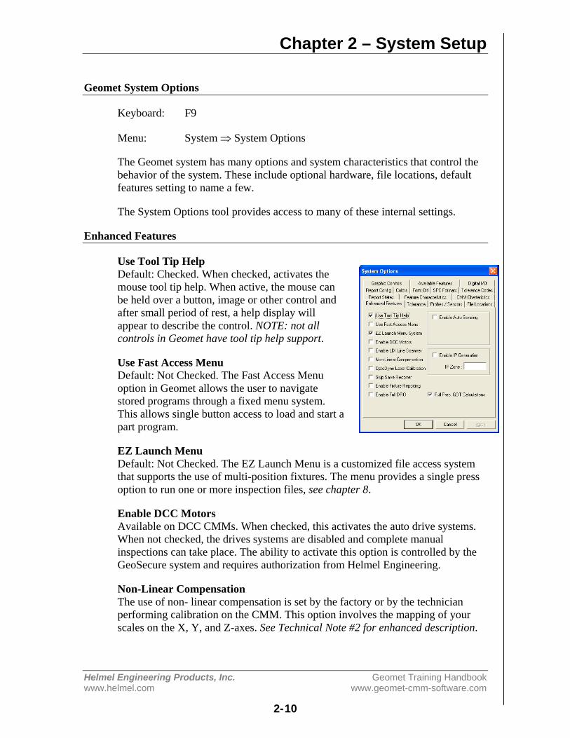
Use Tool Tip HelpDefault: Checked. When checked, activates themouse tool tip help. When active, the mouse canbe held over a button, image or other control andafter small period of rest, a help display willappear to describe the control. NOTE: not allcontrols in Geomet have tool tip help support.
Use Fast Access MenuDefault: Not Checked. The Fast Access Menuoption in Geomet allows the user to navigatestored programs through a fixed menu system.This allows single button access to load and start apart program.
EZ Launch MenuDefault: Not Checked. The EZ Launch Menu is a customized file access systemthat supports the use of multi-position fixtures. The menu provides a single pressoption to run one or more inspection files, see chapter 8.
Enable DCC MotorsAvailable on DCC CMMs. When checked, this activates the auto drive systems.When not checked, the drives systems are disabled and complete manualinspections can take place. The ability to activate this option is controlled by theGeoSecure system and requires authorization from Helmel Engineering.
Non-Linear CompensationThe use of non- linear compensation is set by the factory or by the technicianperforming calibration on the CMM. This option involves the mapping of yourscales on the X, Y, and Z-axes. See Technical Note #2 for enhanced description.

Chapter 2 – System Setup
Helmel Engineering Products, Inc. Geomet Training Handbookwww.helmel.com www.geomet-cmm-software.com
2-11
NOTE: Do not uncheck this option! Your CMM calibration tables will bedeactivated and the accuracy of your CMM will be affected. The calibrationtables are stored in a separate file, "Lerror.dat" which is stored in your Windowsfolder. If you inadvertently uncheck this option, just reset the check mark.
OptoDyne Laser CalibrationWhen activated this option will utilize the 3D volumetric calibration developed incooperation with OptoDyne Inc. This provides compensation not only to thelinear characteristics of the CMM, but also corrects for any squareness andparallelism of the CMM superstructure. Obsolete function.
Skip Save RecoverDefault: Not Checked. During normal operations, Geomet maintains a recoveryfile. This file is updated after the completion of any feature or operation. Thisrequires time and resources to open the recovery file, write the file out to the harddrive, then close the file with every feature. During long part runs or whenoperating on systems with limited capabilities, this feature can be disabled savingtime during part program runs.
Enable Fixture ReportingDefault: Not Checked. On the Header page of a part program, there exists threeedit controls where the operator can enter alphanumeric fixture data. Under mostconditions, this is not required. When checked, the 3 fixture edit controls willappear.
Enable Full DRODefault: Not Checked. When checked, Geomet reconfigures the display to show alarge Digital Read Out in area reserved for the normal graphics. This provides alarge readout of the current position that can be viewed from a great distance suchas moving around the CMM. When the full DRO is active, the normal graphicsdisplay is disabled, see Full DRO in Chapter 8.
Enable Auto SensingDefault: Not Checked. When checked Geomet reconfigures to sense for thecurrent probe direction vector, see Auto-Direction in Chapter 8 for a completedescription. This option is only available on some CMM interfaces that allowtime based monitoring of CMM motion.
Enable IP GenerationDefault: Not Checked. When checked, this activates a monitoring function thatwill create a "memory" of your probe motions for each feature. This saved motionbecomes a motion map to the measured feature. This allows the teaching of thefull motion path in a part program on a manual CMM to be executed on a DCCCMM.
Chapter 2 – System Setup
Helmel Engineering Products, Inc. Geomet Training Handbookwww.helmel.com www.geomet-cmm-software.com
2-12
Full Prec. GDT CalculationsDefault: Checked. When checked, Geomet performs calculations on data arebased on full precision values eliminating rounding errors caused during reportingat a fixed decimal place. For example, if the report decimal place is set at 3 placesand the reported values were transferred to manual calculations such as aspreadsheet, there can exist a rounding error in excess of 0.00149 in the reportingof a 2D true position value. By default, Geomet calculates at full decimalprecision for greater accuracy of results.
Applying your SelectionsWhen finished making all your selections, press the <Apply> button and close theSystem Options by pressing the <Ok> button.

Chapter 2 – System Setup
Helmel Engineering Products, Inc. Geomet Training Handbookwww.helmel.com www.geomet-cmm-software.com
2-13
Tolerance
Geomet maintains 5 tolerance pages wheredefaults can be established. This concept isdesigned to work with the tolerance section foundin the title block on most drawings.
For example, Geomet Tolerance Pages can beconfigured by entering the + / - tolerance valuesand precision settings for reporting against a pagenumber, see table 1.
When you apply the tolerance against a feature,you can select the appropriate tolerance page andthe default values will be applied includingreconfiguring the results for any change in precision.
Tol. Page # Precision Tol. ValuePage 1 0.0 +/- 0.030Page 2 0.00 +/- 0.010Page 3 0.000 +/- 0.005Table 1, Tolerance Page Assignement Example
Should you require resetting to the factory defaults, press the <Reset Defaults>button and close the System Options.
Applying your SelectionsWhen finished making all your selections, press the <Apply> button and close theSystem Options by pressing the <Ok> button.
Chapter 2 – System Setup
Helmel Engineering Products, Inc. Geomet Training Handbookwww.helmel.com www.geomet-cmm-software.com
2-14
Probes and Sensors
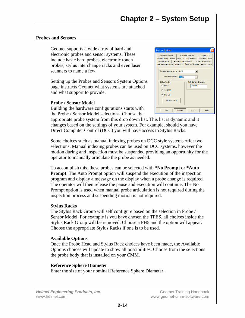
Geomet supports a wide array of hard andelectronic probes and sensor systems. Theseinclude basic hard probes, electronic touchprobes, stylus interchange racks and even laserscanners to name a few.
Setting up the Probes and Sensors System Optionspage instructs Geomet what systems are attachedand what support to provide.
Probe / Sensor ModelBuilding the hardware configurations starts withthe Probe / Sensor Model selections. Choose theappropriate probe system from this drop down list. This list is dynamic and itchanges based on the settings of your system. For example, should you haveDirect Computer Control (DCC) you will have access to Stylus Racks.
Some choices such as manual indexing probes on DCC style systems offer twoselections. Manual indexing probes can be used on DCC systems, however themotion during and inspection must be suspended providing an opportunity for theoperator to manually articulate the probe as needed.
To accomplish this, these probes can be selected with *No Prompt or *AutoPrompt. The Auto Prompt option will suspend the execution of the inspectionprogram and display a message on the display when a probe change is required.The operator will then release the pause and execution will continue. The NoPrompt option is used when manual probe articulation is not required during theinspection process and suspending motion is not required.
Stylus RacksThe Stylus Rack Group will self configure based on the selection in Probe /Sensor Model. For example is you have chosen the TPES, all choices inside theStylus Rack Group will be removed. Choose a PH5 and the option will appear.Choose the appropriate Stylus Racks if one is to be used.
Available OptionsOnce the Probe Head and Stylus Rack choices have been made, the AvailableOptions choices will update to show all possibilities. Choose from the selectionsthe probe body that is installed on your CMM.
Reference Sphere DiameterEnter the size of your nominal Reference Sphere Diameter.
Chapter 2 – System Setup
Helmel Engineering Products, Inc. Geomet Training Handbookwww.helmel.com www.geomet-cmm-software.com
2-15
File Locations
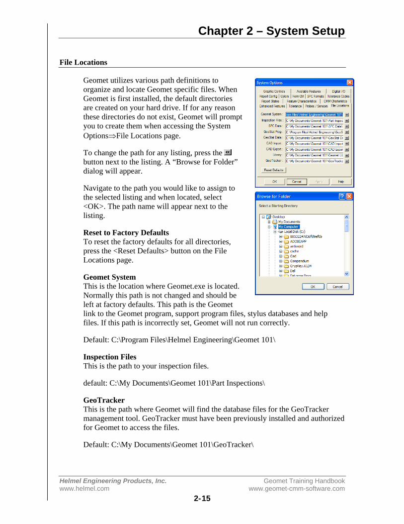
Geomet utilizes various path definitions toorganize and locate Geomet specific files. WhenGeomet is first installed, the default directoriesare created on your hard drive. If for any reasonthese directories do not exist, Geomet will promptyou to create them when accessing the SystemOptions⇒File Locations page.
To change the path for any listing, press the button next to the listing. A “Browse for Folder”dialog will appear.
Navigate to the path you would like to assign tothe selected listing and when located, select<OK>. The path name will appear next to thelisting.
Reset to Factory DefaultsTo reset the factory defaults for all directories,press the <Reset Defaults> button on the FileLocations page.
Geomet SystemThis is the location where Geomet.exe is located.Normally this path is not changed and should beleft at factory defaults. This path is the Geometlink to the Geomet program, support program files, stylus databases and helpfiles. If this path is incorrectly set, Geomet will not run correctly.
Default: C:\Program Files\Helmel Engineering\Geomet 101\
Inspection FilesThis is the path to your inspection files.
default: C:\My Documents\Geomet 101\Part Inspections\
GeoTrackerThis is the path where Geomet will find the database files for the GeoTrackermanagement tool. GeoTracker must have been previously installed and authorizedfor Geomet to access the files.
Default: C:\My Documents\Geomet 101\GeoTracker\
Chapter 2 – System Setup
Helmel Engineering Products, Inc. Geomet Training Handbookwww.helmel.com www.geomet-cmm-software.com
2-16
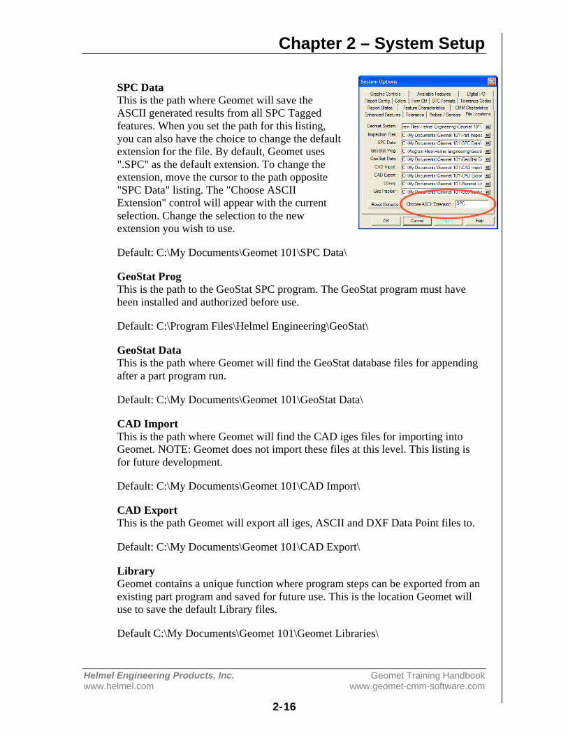
SPC DataThis is the path where Geomet will save theASCII generated results from all SPC Taggedfeatures. When you set the path for this listing,you can also have the choice to change the defaultextension for the file. By default, Geomet uses".SPC" as the default extension. To change theextension, move the cursor to the path opposite"SPC Data" listing. The "Choose ASCIIExtension" control will appear with the currentselection. Change the selection to the newextension you wish to use.
Default: C:\My Documents\Geomet 101\SPC Data\
GeoStat ProgThis is the path to the GeoStat SPC program. The GeoStat program must havebeen installed and authorized before use.
Default: C:\Program Files\Helmel Engineering\GeoStat\
GeoStat DataThis is the path where Geomet will find the GeoStat database files for appendingafter a part program run.
Default: C:\My Documents\Geomet 101\GeoStat Data\
CAD ImportThis is the path where Geomet will find the CAD iges files for importing intoGeomet. NOTE: Geomet does not import these files at this level. This listing isfor future development.
Default: C:\My Documents\Geomet 101\CAD Import\
CAD ExportThis is the path Geomet will export all iges, ASCII and DXF Data Point files to.
Default: C:\My Documents\Geomet 101\CAD Export\
LibraryGeomet contains a unique function where program steps can be exported from anexisting part program and saved for future use. This is the location Geomet willuse to save the default Library files.
Default C:\My Documents\Geomet 101\Geomet Libraries\

Chapter 2 – System Setup
Helmel Engineering Products, Inc. Geomet Training Handbookwww.helmel.com www.geomet-cmm-software.com
2-17
Report States
The Report States page controls the reportingformats used at startup or globally changed duringthe self-teach mode.
Reporting CharacteristicsSelect the small button next to the reportingcharacteristic.
Description Option 1 Option 2Unit of Measure Inch Metric
Angular Reporting xx.xx° dd mm ss°Reporting Format Cartesian Polar
Date Format mm/dd/yy dd/mm/yyCAD Graphics On Off
Digital Readout On Off
Activate these changes for current inspectionBy selecting this option, all selections in Report States will activate immediately.Under normal conditions, Report States control the behavior of the inspectionwhen it creates a new inspection report.
Display Font SizeEnter a font size here that will change the displayed results on the monitor. Thissetting does not change the size on printed reports.
Chapter 2 – System Setup
Helmel Engineering Products, Inc. Geomet Training Handbookwww.helmel.com www.geomet-cmm-software.com
2-18
Feature Characteristics
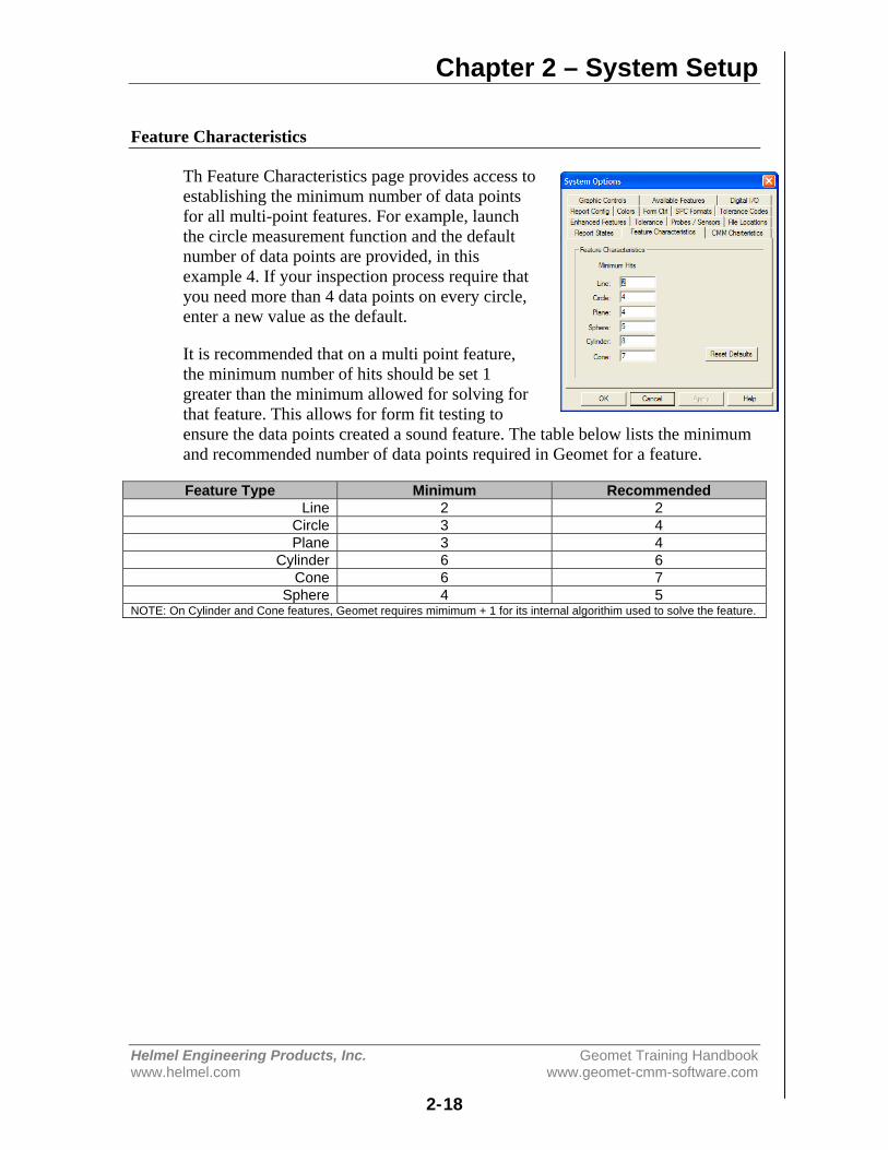
Th Feature Characteristics page provides access toestablishing the minimum number of data pointsfor all multi-point features. For example, launchthe circle measurement function and the defaultnumber of data points are provided, in thisexample 4. If your inspection process require thatyou need more than 4 data points on every circle,enter a new value as the default.
It is recommended that on a multi point feature,the minimum number of hits should be set 1greater than the minimum allowed for solving forthat feature. This allows for form fit testing toensure the data points created a sound feature. The table below lists the minimumand recommended number of data points required in Geomet for a feature.
Feature Type Minimum RecommendedLine 2 2
Circle 3 4Plane 3 4
Cylinder 6 6Cone 6 7
Sphere 4 5NOTE: On Cylinder and Cone features, Geomet requires mimimum + 1 for its internal algorithim used to solve the feature.
Chapter 2 – System Setup
Helmel Engineering Products, Inc. Geomet Training Handbookwww.helmel.com www.geomet-cmm-software.com
2-19
CMM Characteristics
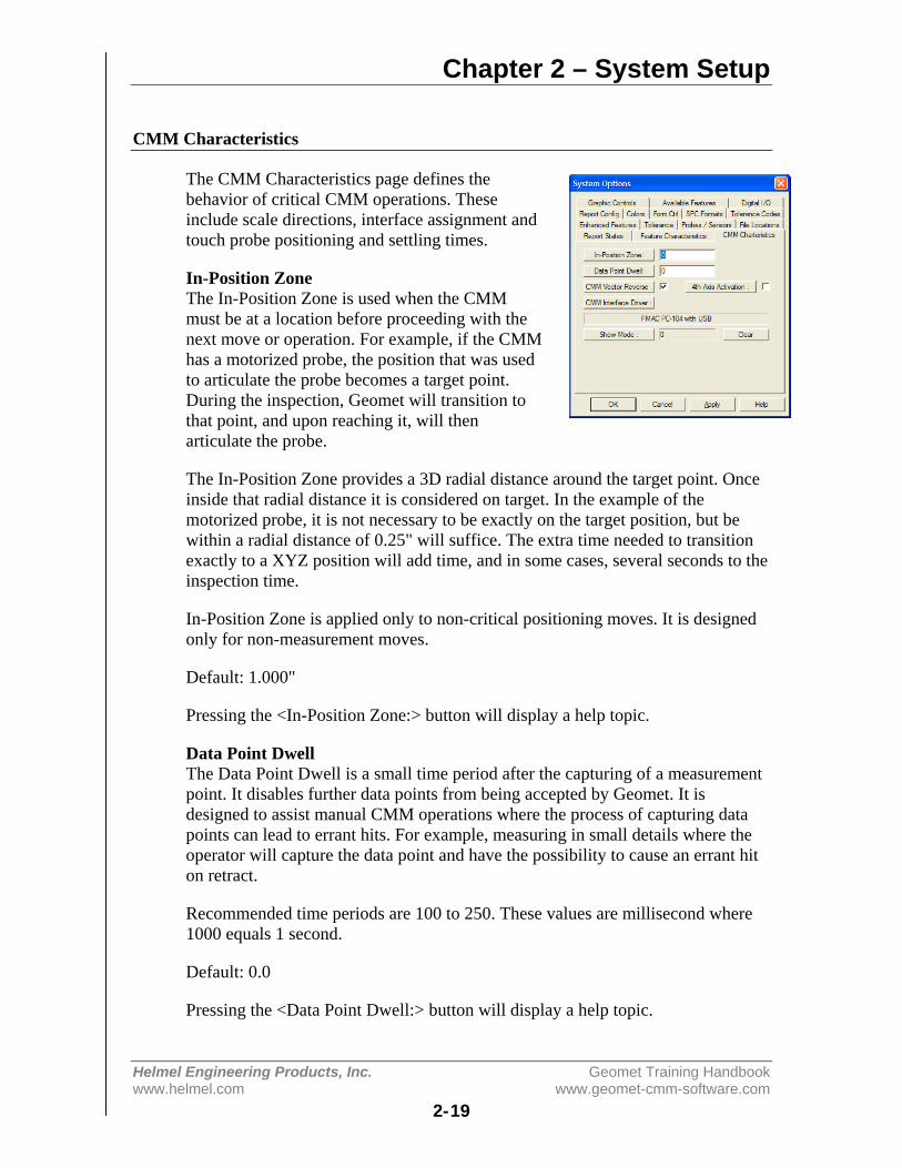
The CMM Characteristics page defines thebehavior of critical CMM operations. Theseinclude scale directions, interface assignment andtouch probe positioning and settling times.
In-Position ZoneThe In-Position Zone is used when the CMMmust be at a location before proceeding with thenext move or operation. For example, if the CMMhas a motorized probe, the position that was usedto articulate the probe becomes a target point.During the inspection, Geomet will transition tothat point, and upon reaching it, will thenarticulate the probe.
The In-Position Zone provides a 3D radial distance around the target point. Onceinside that radial distance it is considered on target. In the example of themotorized probe, it is not necessary to be exactly on the target position, but bewithin a radial distance of 0.25" will suffice. The extra time needed to transitionexactly to a XYZ position will add time, and in some cases, several seconds to theinspection time.
In-Position Zone is applied only to non-critical positioning moves. It is designedonly for non-measurement moves.
Default: 1.000"
Pressing the <In-Position Zone:> button will display a help topic.
Data Point DwellThe Data Point Dwell is a small time period after the capturing of a measurementpoint. It disables further data points from being accepted by Geomet. It isdesigned to assist manual CMM operations where the process of capturing datapoints can lead to errant hits. For example, measuring in small details where theoperator will capture the data point and have the possibility to cause an errant hiton retract.
Recommended time periods are 100 to 250. These values are millisecond where1000 equals 1 second.
Default: 0.0
Pressing the <Data Point Dwell:> button will display a help topic.
Chapter 2 – System Setup
Helmel Engineering Products, Inc. Geomet Training Handbookwww.helmel.com www.geomet-cmm-software.com
2-20
CMM Vector ReverseGeomet is designed to work with many CMMs. Not all CMMs place the scale onthe measuring machine the same way. The scale may read left negative too rightpositive. Others can be reversed. Some CMM models by the same manufacturercan be reversed.
This results in reverse direction sensing in the measuring process. To test yourdirections, set Geomet up for Auto Direction Sensing, activate Auto Direction inyour System Options->Enhanced Features page.
To perform the test, set Geomet up to measure an Auto 1D-Point. Deflect theprobe manually while moving slowly in the +X direction. The point reported inthe inspection report should be a +X Point. Test all six directions and review thereport to determine if they are indeed backwards. A +X Point should not bereported as an -X Point. If they are backwards, place (or remove) the check nextto CMM Vector Reverse.
4th Axis ActivationThis option activates the 4th-Axis inside Geomet. This is commonly used on aCMM that has the rotary motorized table installed or on Helmel's CrankShaftCMM. By activating the 4th-Axis, additional commands are available such as theWobble Coordinate System and Motion Servo commands.
It is recommended that you do not activate this option without first checking withHelmel Technical Support to determine if the motion controller attached to yourCMM has 4th Axis capability. If you add a rotary table, such as a Haas RotaryTable with its own Servo Control, Geomet will be able to read and control thepositioning. However, before these capabilities can be activated, contact HelmelEngineering to the proper software 4th-axis upgrade.
CMM Interface DriverThe current CMM interface is listed here. The actual configuration and activationhas been moved off the System Option page and now resides in GeoClean.
Show ModeThis option allows you to enter a cycle count that Geomet will use whenperforming an inspection. Geomet will automatically cycle the inspectionprogram the number of time you request. The <Clear> button will reset thecounter to zero. This can be done even during the inspection run. The normal useof this mode is for life endurance tests, repeatability tests and trade shows wherethe CMM will cycle a predetermined number of inspections.
NOTE: It is imperative that the ending point of your inspection program has anunobstructed path to the start of the program. Always ensure there is an exiting IPin your part inspection program.
Chapter 2 – System Setup
Helmel Engineering Products, Inc. Geomet Training Handbookwww.helmel.com www.geomet-cmm-software.com
2-21
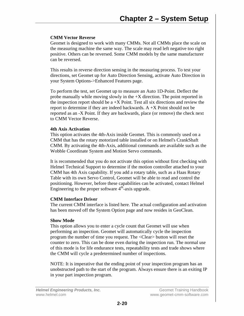
Report Config
The Report Configuration page controls thePrinted Report attributes and is a global setting.
Company Information
This data entry field is where you would put yourcompany name. This is printed on the top line ofthe header block on all printed pages.
Report Characteristcs
Background Shaded BarsDuring the printing of the inspection report,Geomet shades the column header and on theConcise Report format, shades every other line. Some printers do not reproduce asmooth light gray that makes the readability difficult. Use this setting to controlwhether to use shaded bars or not.
Print LinesDuring the printing of the inspection report, Geomet inserts a line after everyfeature to assist in reading the reports. Use this setting to control whether to useseparator lines or not.
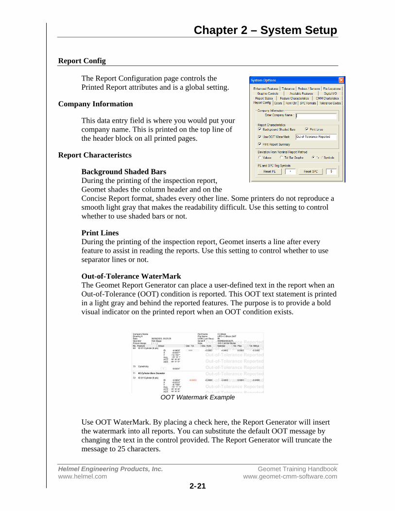
Out-of-Tolerance WaterMarkThe Geomet Report Generator can place a user-defined text in the report when anOut-of-Tolerance (OOT) condition is reported. This OOT text statement is printedin a light gray and behind the reported features. The purpose is to provide a boldvisual indicator on the printed report when an OOT condition exists.
OOT Watermark Example
Use OOT WaterMark. By placing a check here, the Report Generator will insertthe watermark into all reports. You can substitute the default OOT message bychanging the text in the control provided. The Report Generator will truncate themessage to 25 characters.
Chapter 2 – System Setup
Helmel Engineering Products, Inc. Geomet Training Handbookwww.helmel.com www.geomet-cmm-software.com
2-22
Print Report SummaryOn the last page of a printed inspection report is a summary of totals for allfeatures that have a tolerance applied. The reported summary is broken down into:
• Total Tested: A total count of all toleranced features.• Accepted: All features that are within the tolerance limits.• OOT: Total features that exceed the tolerance limits.
When Process Control Tolerance is active, the summary reports the total countwithin each zone, see Process Control Tolerance in Chapter 6 for additionaldetails. To omit this summary line from being printed, uncheck the option PrintReport Summary.
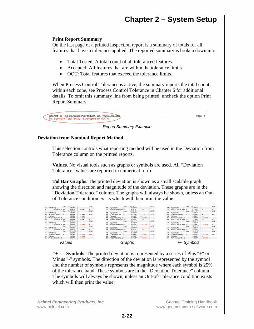
Report Summary Example
Deviation from Nominal Report Method
This selection controls what reporting method will be used in the Deviation fromTolerance column on the printed reports.
Values. No visual tools such as graphs or symbols are used. All “DeviationTolerance” values are reported in numerical form.
Tol Bar Graphs. The printed deviation is shown as a small scalable graphshowing the direction and magnitude of the deviation. These graphs are in the“Deviation Tolerance” column. The graphs will always be shown, unless an Out-of-Tolerance condition exists which will then print the value.
Values Graphs +/- Symbols
"+ - " Symbols. The printed deviation is represented by a series of Plus "+" orMinus "-" symbols. The direction of the deviation is represented by the symboland the number of symbols represents the magnitude where each symbol is 25%of the tolerance band. These symbols are in the “Deviation Tolerance” column.The symbols will always be shown, unless an Out-of-Tolerance condition existswhich will then print the value.
Chapter 2 – System Setup
Helmel Engineering Products, Inc. Geomet Training Handbookwww.helmel.com www.geomet-cmm-software.com
2-23
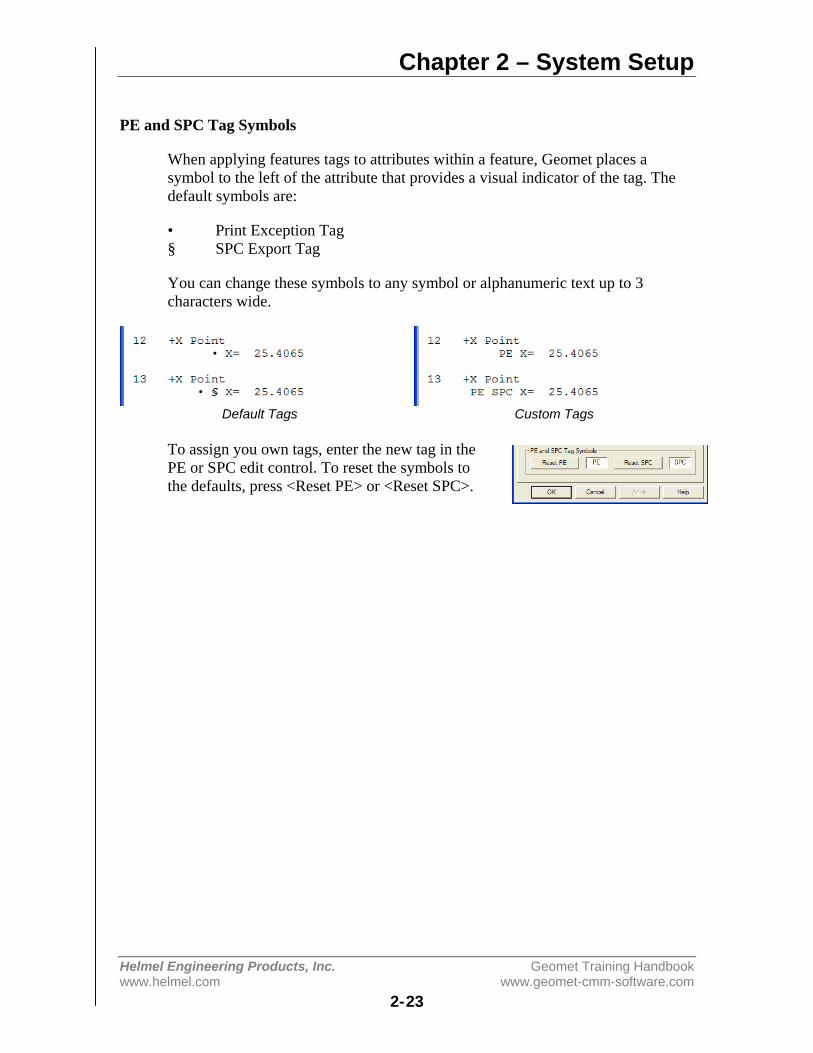
PE and SPC Tag Symbols
When applying features tags to attributes within a feature, Geomet places asymbol to the left of the attribute that provides a visual indicator of the tag. Thedefault symbols are:
• Print Exception Tag§ SPC Export Tag
You can change these symbols to any symbol or alphanumeric text up to 3characters wide.
Default Tags Custom Tags
To assign you own tags, enter the new tag in thePE or SPC edit control. To reset the symbols tothe defaults, press <Reset PE> or <Reset SPC>.
Chapter 2 – System Setup
Helmel Engineering Products, Inc. Geomet Training Handbookwww.helmel.com www.geomet-cmm-software.com
2-24
Colors
The Colors page control the system colors used inthe graphics representation of the inspection.
To change the current color, select the appropriatebutton controlling the feature type.
Color Type DescriptionSolid Sets the color of features displayed in solid
mode.Wireframe Sets the color of features displayed in
wireframe mode.Highlight Sets the color of features while selected
using the mouse point and click.Run Sets the color of the current feature being
inspected durin an auto run.Background Sets the background color.
VP DRO Sets the color of XYZ position values whiletargeting during Vector Point operations.
Saving Custom ColorsGeomet will retain custom colors that you haveselected. The Windows Color Selector requiresthat you follow these steps.
1. Select a swatch location under “Custom colors”.2. Choose or create a color.3. Select <Add to Custom Colors>.

Chapter 2 – System Setup
Helmel Engineering Products, Inc. Geomet Training Handbookwww.helmel.com www.geomet-cmm-software.com
2-25
Form Ctrl
The Form Control page defines limits and featurecontrols used during the self-teach and inspectionmodes within Geomet.
Multi-Point Error LimitThis value is used during the measuring process tovalidate the form of a multi-point feature before itis committed to the inspection report. Forexample, when measuring a circle, it is expectedthat the circularity is better than the form errorlimit. If during the measuring process thecircularity exceeds this form limit (0.001” bydefault), then a warning is provided to allow theoperator to accept or re-measure the feature. This validation process helps tominimize errant data points or poor fitting features.
Default: 0.001"
Use Multi-Point CheckWhen checked, Geomet performs the Multi-Point Error Limit test on all measuredmulti-point features.
Default: Checked
Maximum Reported LimitSets a maximum value for all size and location values being reported. If thisexceeds this value, then the report will show "Exceeds Limit".
Default: 100000000.0
Feature Averaging
Default CyclesSets the default number of cycles used in Feature Averaging.
Default: 5
Default LimitSets the default test value for use with the Feature Averaging Tool.
Default: 0.0002"
For a complete explanation of Feature Averaging, please refer to Chapter 10,Working with Motion Control.
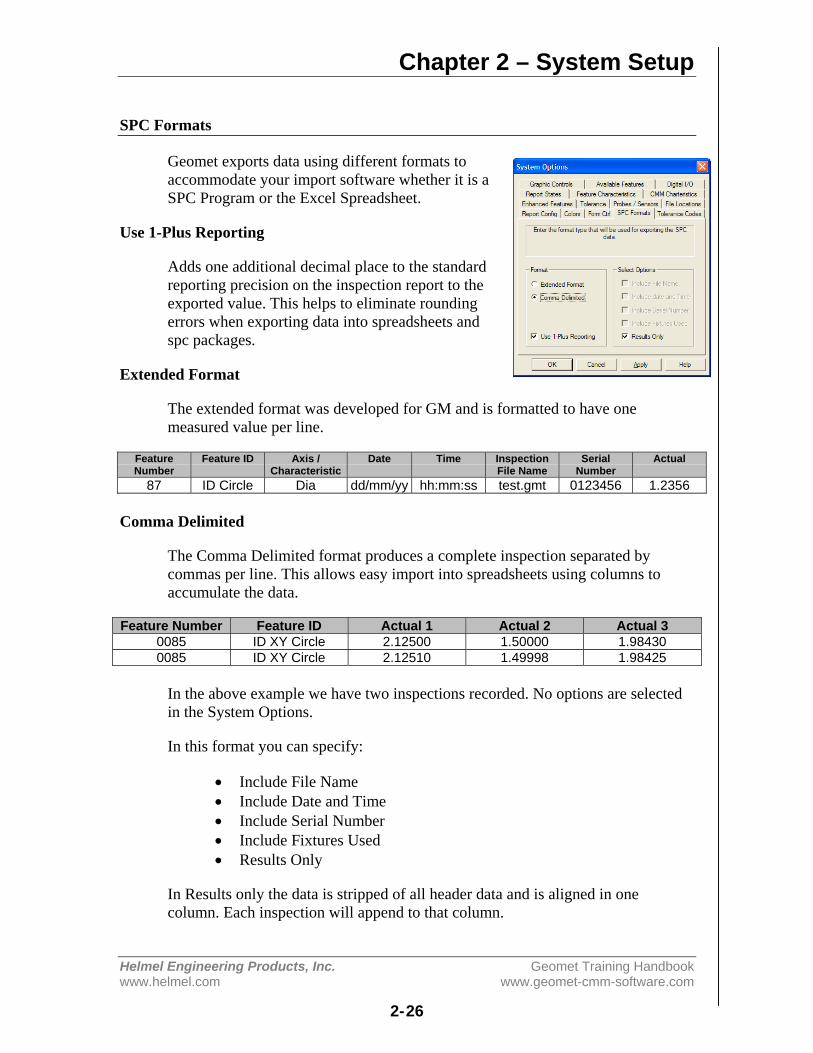
Chapter 2 – System Setup
Helmel Engineering Products, Inc. Geomet Training Handbookwww.helmel.com www.geomet-cmm-software.com
2-26
SPC Formats
Geomet exports data using different formats toaccommodate your import software whether it is aSPC Program or the Excel Spreadsheet.
Use 1-Plus Reporting
Adds one additional decimal place to the standardreporting precision on the inspection report to theexported value. This helps to eliminate roundingerrors when exporting data into spreadsheets andspc packages.
Extended Format
The extended format was developed for GM and is formatted to have onemeasured value per line.
FeatureNumber
Feature ID Axis /Characteristic
Date Time InspectionFile Name
SerialNumber
Actual
87 ID Circle Dia dd/mm/yy hh:mm:ss test.gmt 0123456 1.2356
Comma Delimited
The Comma Delimited format produces a complete inspection separated bycommas per line. This allows easy import into spreadsheets using columns toaccumulate the data.
Feature Number Feature ID Actual 1 Actual 2 Actual 30085 ID XY Circle 2.12500 1.50000 1.984300085 ID XY Circle 2.12510 1.49998 1.98425
In the above example we have two inspections recorded. No options are selectedin the System Options.
In this format you can specify:
• Include File Name• Include Date and Time• Include Serial Number• Include Fixtures Used• Results Only
In Results only the data is stripped of all header data and is aligned in onecolumn. Each inspection will append to that column.
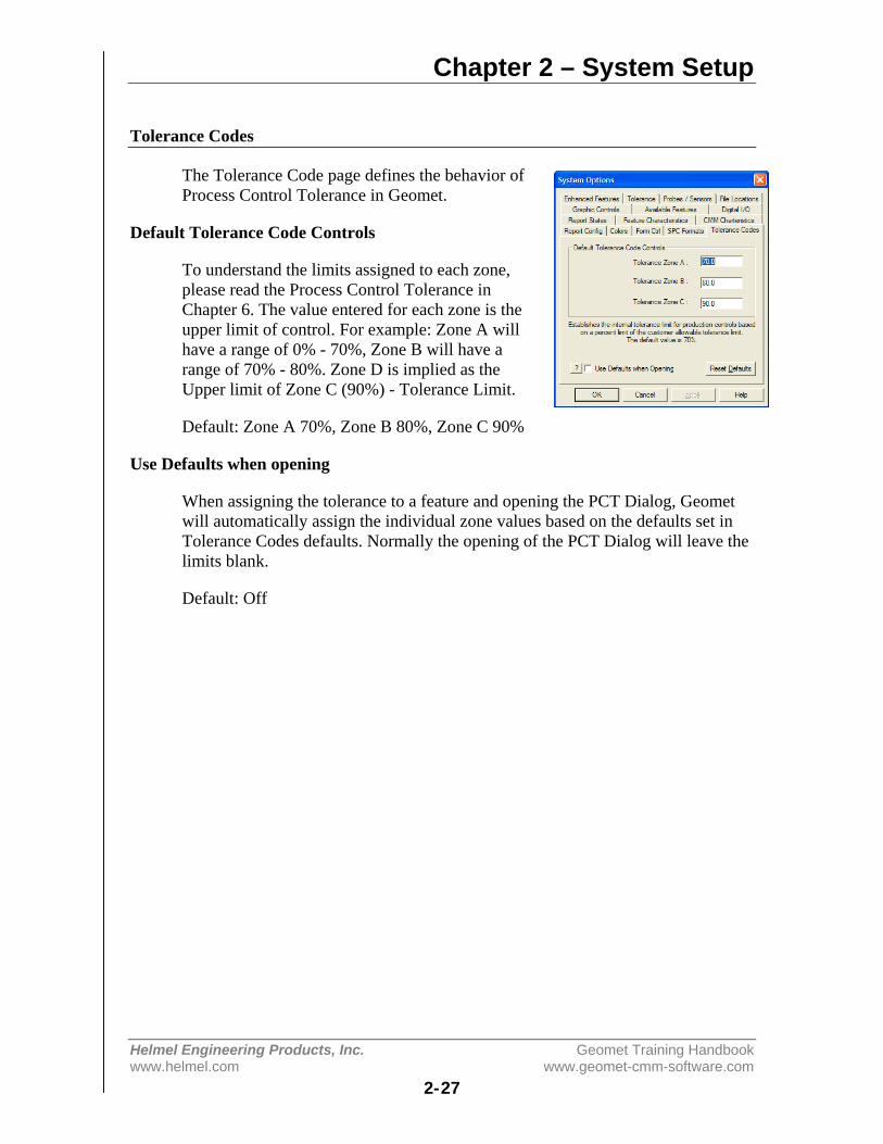
Chapter 2 – System Setup
Helmel Engineering Products, Inc. Geomet Training Handbookwww.helmel.com www.geomet-cmm-software.com
2-27
Tolerance Codes
The Tolerance Code page defines the behavior ofProcess Control Tolerance in Geomet.
Default Tolerance Code Controls
To understand the limits assigned to each zone,please read the Process Control Tolerance inChapter 6. The value entered for each zone is theupper limit of control. For example: Zone A willhave a range of 0% - 70%, Zone B will have arange of 70% - 80%. Zone D is implied as theUpper limit of Zone C (90%) - Tolerance Limit.
Default: Zone A 70%, Zone B 80%, Zone C 90%
Use Defaults when opening
When assigning the tolerance to a feature and opening the PCT Dialog, Geometwill automatically assign the individual zone values based on the defaults set inTolerance Codes defaults. Normally the opening of the PCT Dialog will leave thelimits blank.
Default: Off

Chapter 2 – System Setup
Helmel Engineering Products, Inc. Geomet Training Handbookwww.helmel.com www.geomet-cmm-software.com
2-28
Graphic Controls
The Graphic Options page defines the behavior ofCAD Graphics region in Geomet.
Activate Quick Zooms
This mode toggles the display between standardlayout where results and graphics share thedisplay equally. However, when you position themouse in the graphics area, the display changesgiving the graphics area 90% of the availablewidth. Move the mouse off the graphics area, andthe layout returns to equally shared regions.
Default: Off
Data Clouds as Points
Data Point Clouds, which are captured with the GeoTracer and other scanningtools are displayed with connecting lines. When this option is selected, the displayof the data points is shown as points or dots on the display.
Default: Off
Add Wire Frame to Solids
When displaying the measured results in solid mode, edges are normally turnedoff. When this option is selected, a complete wire frame edge is shown on top ofthe solid features.
Default: OFF
Auto Zoom
Under normal operation, new features are added to the graphic lists, but if they areoutside of the current view port, they will not be seen. When this option isselected, the view port is recalculated to show the total extents of all features asthey are added.
This includes the current coordinate system that may lead to an unusable graphicpresentation. For example if you are working in a coordinate system that has beentranslated a great distance, such as car coordinates, the resulting measured featuremay display as a small group located in the corner of the display.
Default: Off

Chapter 2 – System Setup
Helmel Engineering Products, Inc. Geomet Training Handbookwww.helmel.com www.geomet-cmm-software.com
2-29
Snap Angle
The Snap Angle controls the dynamic positioning by positioning the rotations onfixed positions. Dynamic positioning is available when selecting "Custom View"and interacting with the graphics display with the mouse, see Graphic Views andControls.
Snap mode is available when performing this dynamic positioning and holdingthe <Shift> key down.
Default: 15°
Point Size
This option controls the point size for export in IGES files.
NOTE: This value is not available at this time.
Default: 1
Graphic Cursor Selection
Choose the desired mouse cursor for use over the graphics region. The handcursor has a selection pixel of 8x8. The small box has a selection size of 8x8 andthe large box cursor is 16x16 pixels.
Default: hand

Chapter 2 – System Setup
Helmel Engineering Products, Inc. Geomet Training Handbookwww.helmel.com www.geomet-cmm-software.com
2-30
CMM Scale Compensation
Coordinate Measuring Machines utilize scales that are mounted to each axis ofmotion will require compensation. This compensation will correct for any lineardeviations identified during CMM calibration.
A certified Master Scale or Laser system is used to compare against the reportedposition from the CMM Digital Readout. This deviation can then bemathematically corrected. This information must be supplied to your CMMsoftware to properly measure. There are two main types of scale comparisontechnologies. These are Linear and Non-Linear Compensation.
For additional information refer to Technical Note #2, Inherent Errors located inAppendix 1.
Linear Compensation
Linear Compensation is a single correction value used to compensate the fulllength of travel. For example; if your CMM has a Y-axis travel of 10.0”, youwould test the reported position at its extent against the master scale.
Position Reported by Laser CMM Digital Readout Compensation value10.00000 10.00235 0.99976505
The value, 0.99976505, would be entered in the Linear Setup Tool for the Y-axisand that value becomes the multiplier for all positions. Geomet will use thefollowing formula to compensate for position:
XDRO Reported Value * XCompensation = XCorrected PositionYDRO Reported Value * YCompensation = YCorrected PositionZDRO Reported Value * ZCompensation = ZCorrected Position
All reported values that pass into Geomet will be passed through the LinearCompensation tool prior to being used for any calculations.

Chapter 2 – System Setup
Helmel Engineering Products, Inc. Geomet Training Handbookwww.helmel.com www.geomet-cmm-software.com
2-31
Activating the Linear Setup Tool
Keyboard: <Alt + Ctrl + shift + F2>
Taking a Tour of the Linear Setup Tool
The controlled data is shown in the upper section of the tool where the enteredand calculated axis values are shown.
Calculate Compensation
When performing a calibration, there are three values per axis. Two of whichmust be entered and the third will be calculated. In the example above, theoperator enters the Reference Length and reported Measured Length. The thirdvalue, Compensation Value will be calculated.
Reference Length:This is the reported position from the Master Scale or Laser.
Measured Length:This is the reported uncompensated Digital Readout value scale position.
Compensated Value:The compensated value is the result of Reference Length / Measured Length.
Position Comparison Group
Selecting the Active AxisIn this area choose the axis you wish to calibrate.
Chapter 2 – System Setup
Helmel Engineering Products, Inc. Geomet Training Handbookwww.helmel.com www.geomet-cmm-software.com
2-32
No CompensationThis data field shows the current position directly from the CMM scales with nocompensation applied.
With CompensationAs the name suggests, this is the reported position with the current compensationapplied. This is the result of (Using the x-axis as the example):
XNo Compensation Position * XCompensation = XWith Compensation Position
DifferenceThis reported value is the spread between the No Compensation and WithCompensation positions.
Min, Max, SpreadThese values will update when the <Start / Stop Test> button has been pressed.This reports the difference value while moving the CMM along the selected axis.Use it to determine the total spread that will occur over the full length of travel.
Functions
<DRO>Toggles the visible state of the standard Geomet Digital Readout.
<DRO Xfer>Copies the current position into the Measured Length data field. This value is theun-compensated position shown in the No Compensation data field.
<Zero Axis>Sends an offset position to the internal counter that changes the current position to0.000. This is used to zero the current position and is done in conjunction with thesetting of the zero position for the Master Scale or Laser making both devicesequal at that position.
When the zero option has been applied to an axis, there is a visual reminder,“Zero Set”, next to the axis.
<Clear Zero>Removes a previous zero offset value from the selected axis.
<Update Compensation>This command transfers the calculated Compensation Value from the Setup Toolinto Geomet. This is used when displaying the Geomet DRO for comparison. Thiscommand is optional.

Chapter 2 – System Setup
Helmel Engineering Products, Inc. Geomet Training Handbookwww.helmel.com www.geomet-cmm-software.com
2-33
<Enter Compensation Factors>This command is a push-on / push-off button. It toggles the disabled state of theMeasured Length and Compensation Values columns. When providing theReference Length and Measured Value, this button is off which will disable theCompensation Value. It is used when only the Compensation Value is providedfor calibration.
<Start / Stop Test>The test is designed to capture the minimum, maximum and spread for the entirelength of the selected axis. To use, start the test by pressing the button once. Amessage will appear indicating the test is active. Move the CMM along theselected axis. The test values will display providing the variations along thetravel.
Setting the Compensation Value
The process of determining the compensation values requires the use of a MasterScale or Laser system.
Master ScaleIf used a master scale, a reader head is mounted on the CMM probe bar and thecertified scale is mounted inline with the axis to test. The reader head is adjustedto read the scale over the full length of travel. Once the alignment has beencompleted, move the CMM back to a starting point. For example in the Y-axis,move the CMM to its most –Y position.
Zero the digital Readout that is used to report the position along the master scale.In the Linear Setup Tool, ensure the correct axis is elected (Y Position) and pressthe <Zero Axis> button. This action will result in the master scale and CMMreadout both reporting 0.000.
Move the CMM slowly in the +Y direction until you reach the furthest position.The master scale will report a linear position, which is then entered into the Ref.Lgth column for the y-axis. In the No Compensation position field you will findthe CMM readout value. Transfer this value into the Meas. Lgth column bypressing the <DRO Xfer> button. When this is accomplished, the compensationValue is automatically updated and the updated position in the WithCompensation field should match the master scale position.
Repeat this procedure for each axis. To verify the compensation value, use the<Start / Stop Test> function.
Using a LaserThe procedure is the same as described for Master Scale.
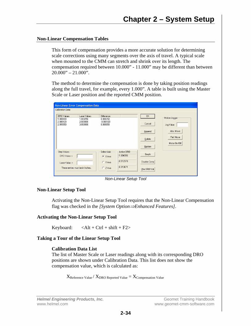
Chapter 2 – System Setup
Helmel Engineering Products, Inc. Geomet Training Handbookwww.helmel.com www.geomet-cmm-software.com
2-34
Non-Linear Compensation Tables
This form of compensation provides a more accurate solution for determiningscale corrections using many segments over the axis of travel. A typical scalewhen mounted to the CMM can stretch and shrink over its length. Thecompensation required between 10.000” - 11.000” may be different than between20.000” – 21.000”.
The method to determine the compensation is done by taking position readingsalong the full travel, for example, every 1.000”. A table is built using the MasterScale or Laser position and the reported CMM position.
Non-Linear Setup Tool
Non-Linear Setup Tool
Activating the Non-Linear Setup Tool requires that the Non-Linear Compensationflag was checked in the [System Option⇒Enhanced Features].
Activating the Non-Linear Setup Tool
Keyboard: <Alt + Ctrl + shift + F2>
Taking a Tour of the Linear Setup Tool
Calibration Data ListThe list of Master Scale or Laser readings along with its corresponding DROpositions are shown under Calibration Data. This list does not show thecompensation value, which is calculated as:
XReference Value / XDRO Reported Value = XCompensation Value

Chapter 2 – System Setup
Helmel Engineering Products, Inc. Geomet Training Handbookwww.helmel.com www.geomet-cmm-software.com
2-35
Selecting an entry in the data list will bring the position values down into editcontrols labeled DRO Value -> and Laser Value ->. From the edit controlschanges can be made when performing or editing a calibration.
<Append>When building the data list, new entries are added by entering the reference andDRO positions in the Step Value Group. Pressing <Append> will then transferthat data into the list. This list performs a sort to keep the list in linear order.
<Delete>Removes the selected position from the data list.
<Update>When a position record is selected, changes can be made to the laser and DROposition values. Once the changes have been completed, press <Update> totransfer the changes into the data list.
<Graph>Displays a graph of the position difference values. This graph can be printed forthe current axis or for all three axes.
<Disable Comp>When <Disable Comp> is active, Non-Linear compensation is deactivated and theCMM will use Linear Calibration. When pressing, the Non-Linear tables aresaved to the data file.
<Xfer DRO Val.>Moves the current position displayed in the Active DRO Group into the editcontrol labeled DRO Value ->.
Motion Jogger Group
The Motion Jogger Group is available on CMMs that have a motion controller.
<Abs. Move>Positions the CMM under DCC to the absolute position entered in Jog Value.
<Rel. Move>Positions the CMM under DCC to the relative step position entered in Jog Value.
<Motor On/Off>Toggles the state of the motors between On or Off.
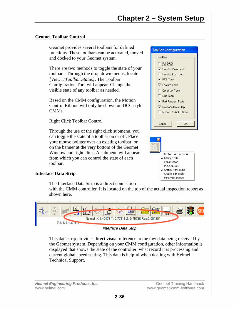
Chapter 2 – System Setup
Helmel Engineering Products, Inc. Geomet Training Handbookwww.helmel.com www.geomet-cmm-software.com
2-36
Geomet Toolbar Control
Geomet provides several toolbars for definedfunctions. These toolbars can be activated, movedand docked to your Geomet system.
There are two methods to toggle the state of yourtoolbars. Through the drop down menus, locate[View⇒Toolbar Status]. The ToolbarConfiguration Tool will appear. Change thevisible state of any toolbar as needed.
Based on the CMM configuration, the MotionControl Ribbon will only be shown on DCC styleCMMs.
Right Click Toolbar Control
Through the use of the right click submenu, youcan toggle the state of a toolbar on or off. Placeyour mouse pointer over an existing toolbar, oron the banner at the very bottom of the GeometWindow and right click. A submenu will appearfrom which you can control the state of eachtoolbar.
Interface Data Strip
The Interface Data Strip is a direct connectionwith the CMM controller. It is located on the top of the actual inspection report asshown here.
Interface Data Strip
This data strip provides direct visual reference to the raw data being received bythe Geomet system. Depending on your CMM configuration, other information isdisplayed that shows the state of the controller, what record it is processing andcurrent global speed setting. This data is helpful when dealing with HelmelTechnical Support.
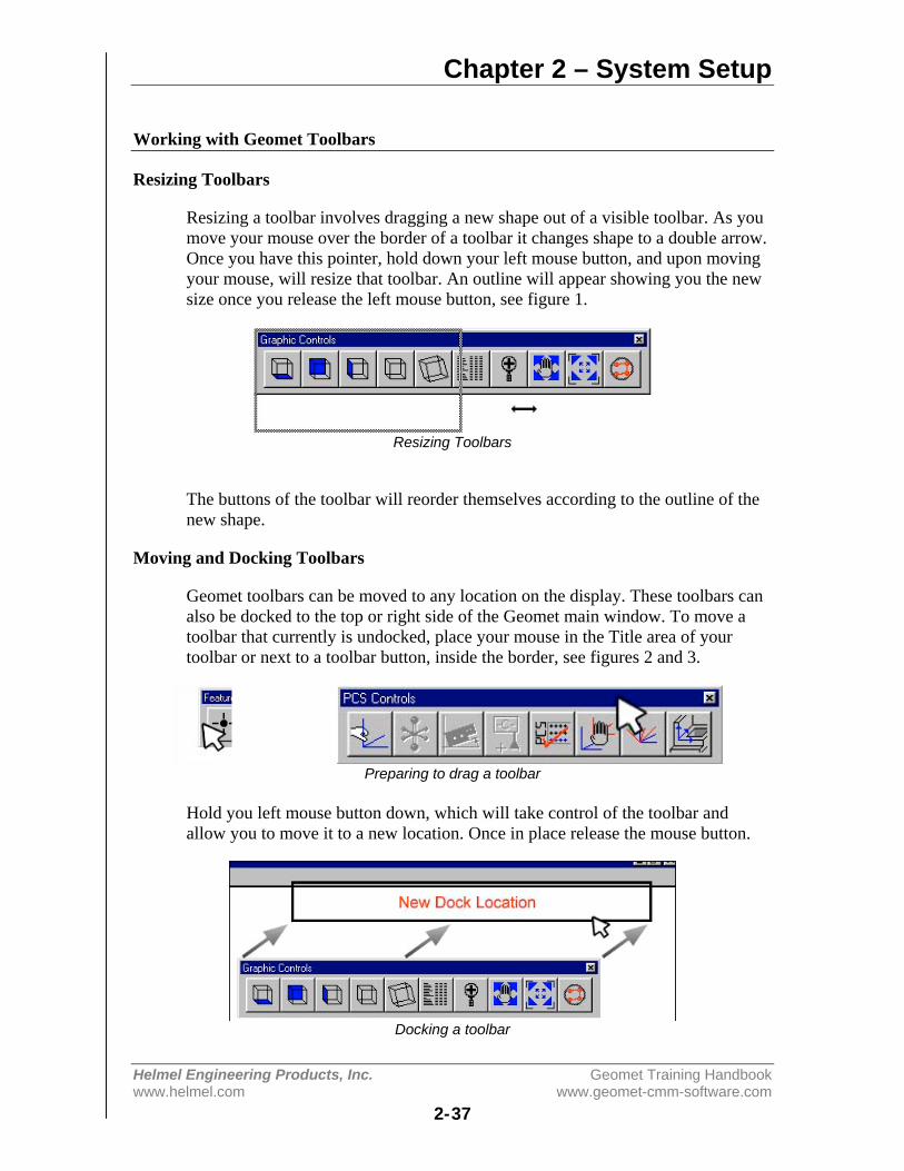
Chapter 2 – System Setup
Helmel Engineering Products, Inc. Geomet Training Handbookwww.helmel.com www.geomet-cmm-software.com
2-37
Working with Geomet Toolbars
Resizing Toolbars
Resizing a toolbar involves dragging a new shape out of a visible toolbar. As youmove your mouse over the border of a toolbar it changes shape to a double arrow.Once you have this pointer, hold down your left mouse button, and upon movingyour mouse, will resize that toolbar. An outline will appear showing you the newsize once you release the left mouse button, see figure 1.
Resizing Toolbars
The buttons of the toolbar will reorder themselves according to the outline of thenew shape.
Moving and Docking Toolbars
Geomet toolbars can be moved to any location on the display. These toolbars canalso be docked to the top or right side of the Geomet main window. To move atoolbar that currently is undocked, place your mouse in the Title area of yourtoolbar or next to a toolbar button, inside the border, see figures 2 and 3.
Preparing to drag a toolbar
Hold you left mouse button down, which will take control of the toolbar andallow you to move it to a new location. Once in place release the mouse button.
Docking a toolbar
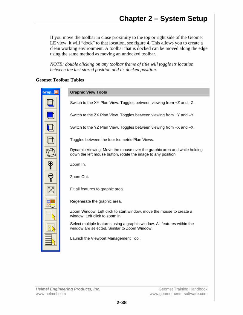
Chapter 2 – System Setup
Helmel Engineering Products, Inc. Geomet Training Handbookwww.helmel.com www.geomet-cmm-software.com
2-38
If you move the toolbar in close proximity to the top or right side of the GeometLE view, it will “dock” to that location, see figure 4. This allows you to create aclean working environment. A toolbar that is docked can be moved along the edgeusing the same method as moving an undocked toolbar.
NOTE: double clicking on any toolbar frame of title will toggle its locationbetween the last stored position and its docked position.
Geomet Toolbar Tables
Graphic View Tools
Switch to the XY Plan View. Toggles between viewing from +Z and –Z.
Switch to the ZX Plan View. Toggles between viewing from +Y and –Y.
Switch to the YZ Plan View. Toggles between viewing from +X and –X.
Toggles between the four Isometric Plan Views.
Dynamic Viewing. Move the mouse over the graphic area and while holdingdown the left mouse button, rotate the image to any position.
Zoom In.
Zoom Out.
Fit all features to graphic area.
Regenerate the graphic area.
Zoom Window. Left click to start window, move the mouse to create awindow. Left click to zoom in.
Select multiple features using a graphic window. All features within thewindow are selected. Similar to Zoom Window.
Launch the Viewport Management Tool.
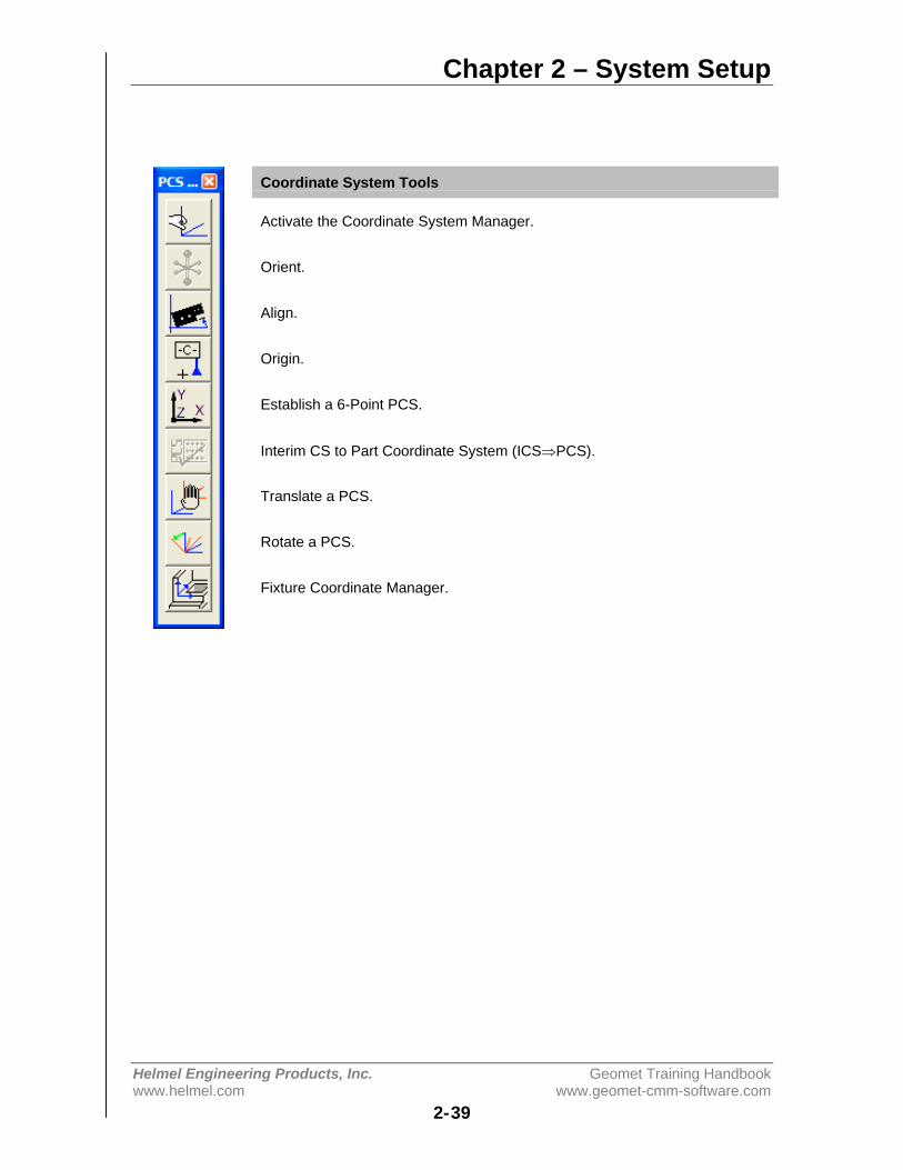
Chapter 2 – System Setup
Helmel Engineering Products, Inc. Geomet Training Handbookwww.helmel.com www.geomet-cmm-software.com
2-39
Coordinate System Tools
Activate the Coordinate System Manager.
Orient.
Align.
Origin.
Establish a 6-Point PCS.
Interim CS to Part Coordinate System (ICS⇒PCS).
Translate a PCS.
Rotate a PCS.
Fixture Coordinate Manager.
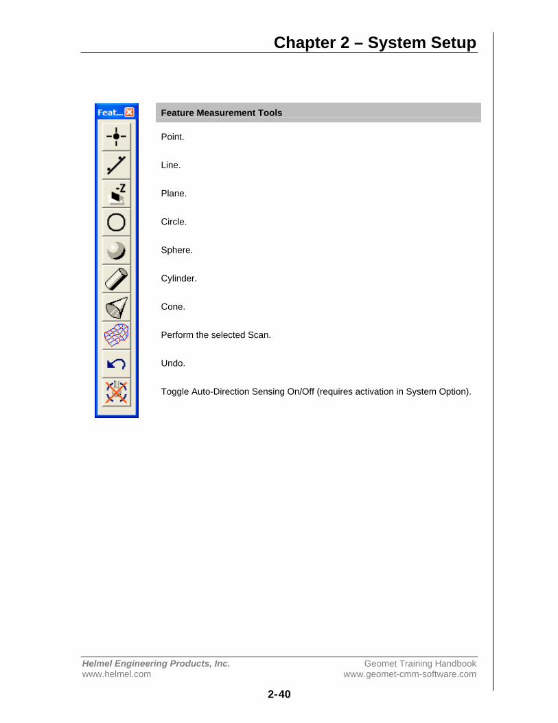
Chapter 2 – System Setup
Helmel Engineering Products, Inc. Geomet Training Handbookwww.helmel.com www.geomet-cmm-software.com
2-40
Feature Measurement Tools
Point.
Line.
Plane.
Circle.
Sphere.
Cylinder.
Cone.
Perform the selected Scan.
Undo.
Toggle Auto-Direction Sensing On/Off (requires activation in System Option).
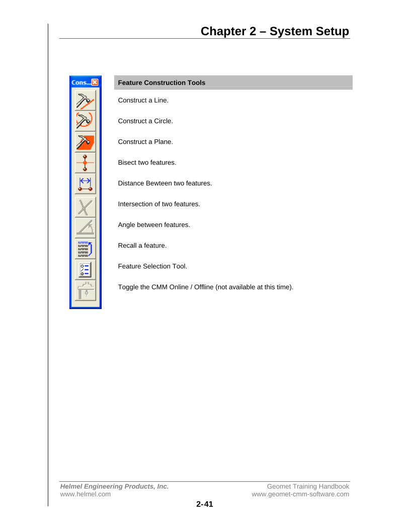
Chapter 2 – System Setup
Helmel Engineering Products, Inc. Geomet Training Handbookwww.helmel.com www.geomet-cmm-software.com
2-41
Feature Construction Tools
Construct a Line.
Construct a Circle.
Construct a Plane.
Bisect two features.
Distance Bewteen two features.
Intersection of two features.
Angle between features.
Recall a feature.
Feature Selection Tool.
Toggle the CMM Online / Offline (not available at this time).
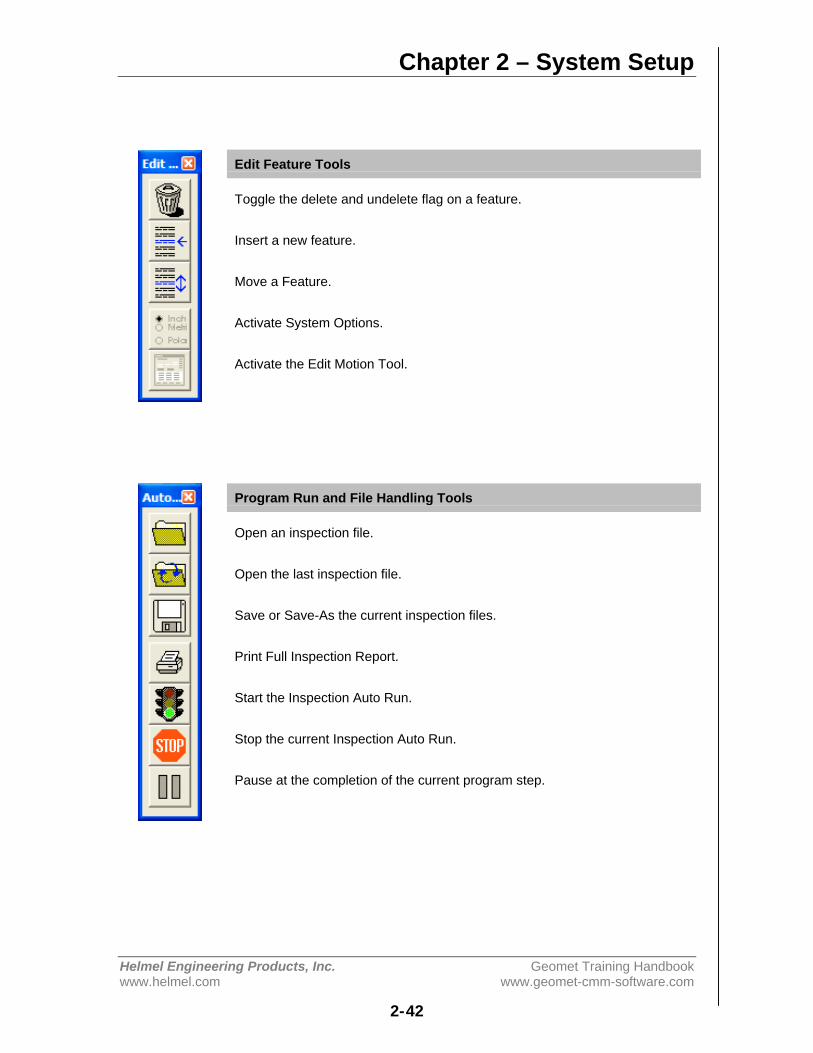
Chapter 2 – System Setup
Helmel Engineering Products, Inc. Geomet Training Handbookwww.helmel.com www.geomet-cmm-software.com
2-42
Edit Feature Tools
Toggle the delete and undelete flag on a feature.
Insert a new feature.
Move a Feature.
Activate System Options.
Activate the Edit Motion Tool.
Program Run and File Handling Tools
Open an inspection file.
Open the last inspection file.
Save or Save-As the current inspection files.
Print Full Inspection Report.
Start the Inspection Auto Run.
Stop the current Inspection Auto Run.
Pause at the completion of the current program step.
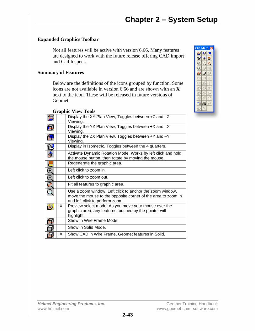
Chapter 2 – System Setup
Helmel Engineering Products, Inc. Geomet Training Handbookwww.helmel.com www.geomet-cmm-software.com
2-43
Expanded Graphics Toolbar
Not all features will be active with version 6.66. Many featuresare designed to work with the future release offering CAD importand Cad Inspect.
Summary of Features
Below are the definitions of the icons grouped by function. Someicons are not available in version 6.66 and are shown with an Xnext to the icon. These will be released in future versions ofGeomet.
Graphic View ToolsDisplay the XY Plan View, Toggles between +Z and –ZViewing.Display the YZ Plan View, Toggles between +X and –XViewing.Display the ZX Plan View, Toggles between +Y and –YViewing.Display in Isometric, Toggles between the 4 quarters.
Activate Dynamic Rotation Mode, Works by left click and holdthe mouse button, then rotate by moving the mouse.Regenerate the graphic area.
Left click to zoom in.
Left click to zoom out.
Fit all features to graphic area.
Use a zoom window. Left click to anchor the zoom window,move the mouse to the opposite corner of the area to zoom inand left click to perform zoom.
X Preview select mode. As you move your mouse over thegraphic area, any features touched by the pointer willhighlight.Show in Wire Frame Mode.Show in Solid Mode.
X Show CAD in Wire Frame, Geomet features in Solid.
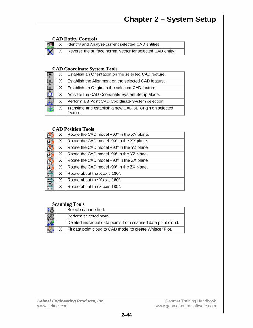
Chapter 2 – System Setup
Helmel Engineering Products, Inc. Geomet Training Handbookwww.helmel.com www.geomet-cmm-software.com
2-44
CAD Entity ControlsX Identify and Analyze current selected CAD entities.X Reverse the surface normal vector for selected CAD entity.
CAD Coordinate System ToolsX Establish an Orientation on the selected CAD feature.X Establish the Alignment on the selected CAD feature.X Establish an Origin on the selected CAD feature.X Activate the CAD Coordinate System Setup Mode.X Perform a 3 Point CAD Coordinate System selection.X Translate and establish a new CAD 3D Origin on selected
feature.
CAD Position ToolsX Rotate the CAD model +90° in the XY plane.X Rotate the CAD model -90° in the XY plane.X Rotate the CAD model +90° in the YZ plane.X Rotate the CAD model -90° in the YZ plane.X Rotate the CAD model +90° in the ZX plane.X Rotate the CAD model -90° in the ZX plane.X Rotate about the X axis 180°.X Rotate about the Y axis 180°.X Rotate about the Z axis 180°.
Scanning ToolsSelect scan method.Perform selected scan.Deleted individual data points from scanned data point cloud.
X Fit data point cloud to CAD model to create Whisker Plot.
Chapter 3 – Stylus Management
Helmel Engineering Products, Inc. Geomet Training Handbookwww.helmel.com www.geomet-cmm-software.com
3-1
Chapter 3 – Stylus Management
Stylus Manager .................................................................................. 3-2Probe Qualification Process......................................................... 3-2Stylus Manager Sub Menus ......................................................... 3-2Deleting Stylus............................................................................. 3-3Remove Pre-Qualified Stylus ...................................................... 3-6Duplicate a Stylus ........................................................................ 3-7Labeling a Stylus ......................................................................... 3-8
Qualifying a Ball Stylus..................................................................... 3-9
Qualifying Ball Styli in Multiple Positions ..................................... 3-10Note on Reference Sphere Location .......................................... 3-10
Entering a Known Probe Diameter .................................................. 3-11
Stylus Tip Relationships .................................................................. 3-12
Qualifying with a Motorized Probe Head........................................ 3-13
Qualifying with a Stylus Change Rack............................................ 3-15
Qualifying a Motorized Probe Head and Stylus Change Rack........ 3-18
Stylus Database Manager................................................................. 3-19Create a new Stylus Database .................................................... 3-20Import a Stylus Database ........................................................... 3-20Delete a Stylus Database Listing ............................................... 3-21Set active a Stylus Database ...................................................... 3-21Loading a Part Program ............................................................. 3-22
Renishaw SCR200/MCR 20 Stylus Rack Setup.............................. 3-24
Renishaw SCR200/MCR20 Maintenance Operations ..................... 3-31
Stylus Database Edit Control ........................................................... 3-35

Chapter 3 – Stylus Management
Helmel Engineering Products, Inc. Geomet Training Handbookwww.helmel.com www.geomet-cmm-software.com
3-2
Stylus Manager
Geomet maintains a database of known, qualified styli. Each stylus used isqualified against a standard reference sphere to identify the size and MCSlocation. Knowing the size and location allows Geomet to properly applycompensation to all measured features. Knowing the location allows the switchingof the styli between positions in a cluster or an articulating probe head such as themotorized Renishaw PH10.
Stylus Management is handled by the Stylus Manager that contains all the toolsnecessary for qualifying, re-qualifying and choosing a stylus for use in measuring.The configuration of all your stylus hardware is maintained in the System Optionson the Probes and Sensors page.
The Stylus Manager is activated by:
Keyboard: w
Menu: Qualify->Stylus Manager
Probe Qualification Process
After qualifying the first stylus, Geomet maintains that position as the referenceposition for the entire stylus database. When adding additional styli, Geometmaintains the location relationship between the newly qualified stylus and the firststylus. This relationship is applied when setting any stylus active and allowscorrect compensation for any qualified position, even in the same feature, withoutloss of accuracy.

Chapter 3 – Stylus Management
Helmel Engineering Products, Inc. Geomet Training Handbookwww.helmel.com www.geomet-cmm-software.com
3-3
Stylus Manager Sub Menu Tools
There exists a sub menu that can be called up to react directly with the list ofstylus records. To activate the sub menu, right-click in the list area and the submenu will appear.
Through the sub menu you have access to three functions. These are:
• Delete Stylus• Duplicate Stylus• Edit Label
All three functions work on the highlighted stylus, but only the Delete Stylus hasmore than one feature. When a stylus is highlighted, the delete function willdelete only that stylus. When there are no stylus selected, the delete will clear allstylus information from the database.

Chapter 3 – Stylus Management
Helmel Engineering Products, Inc. Geomet Training Handbookwww.helmel.com www.geomet-cmm-software.com
3-4
Deleting Stylus from the Stylus Manager
Summary
Deleting a stylus will remove from the database all information regarding positionand size. Caution should be taken when deleting a stylus from the database.Geomet will mark any styli missing as Pre-Qualify when opening an inspectionthat requires the deleted tip.
• Delete a single Stylus• Delete all Stylus• Remove all Pre-Qualified Stylus
Delete a Single Stylus
Step 1
Activating the Stylus Manager can be done through the use of the 'w' keystroke orthrough the drop down menus [Qualify->Stylus Manager].
The Stylus Manager will display all current, qualified styli and pre-qualified styli.The current active stylus is shown with an arrow located next to it.
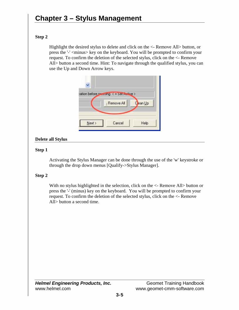
Chapter 3 – Stylus Management
Helmel Engineering Products, Inc. Geomet Training Handbookwww.helmel.com www.geomet-cmm-software.com
3-5
Step 2
Highlight the desired stylus to delete and click on the <- Remove All> button, orpress the '-' <minus> key on the keyboard. You will be prompted to confirm yourrequest. To confirm the deletion of the selected stylus, click on the <- RemoveAll> button a second time. Hint: To navigate through the qualified stylus, you canuse the Up and Down Arrow keys.
Delete all Stylus
Step 1
Activating the Stylus Manager can be done through the use of the 'w' keystroke orthrough the drop down menus [Qualify->Stylus Manager].
Step 2
With no stylus highlighted in the selection, click on the <- Remove All> button orpress the '-' (minus) key on the keyboard. You will be prompted to confirm yourrequest. To confirm the deletion of the selected stylus, click on the <- RemoveAll> button a second time.
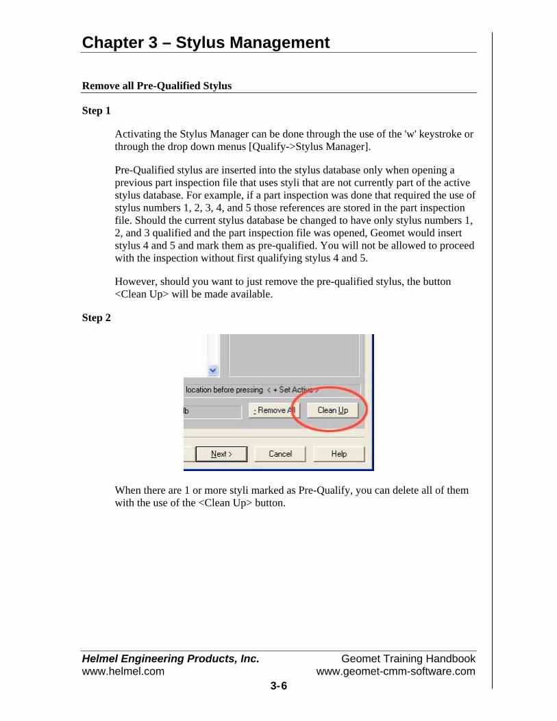
Chapter 3 – Stylus Management
Helmel Engineering Products, Inc. Geomet Training Handbookwww.helmel.com www.geomet-cmm-software.com
3-6
Remove all Pre-Qualified Stylus
Step 1
Activating the Stylus Manager can be done through the use of the 'w' keystroke orthrough the drop down menus [Qualify->Stylus Manager].
Pre-Qualified stylus are inserted into the stylus database only when opening aprevious part inspection file that uses styli that are not currently part of the activestylus database. For example, if a part inspection was done that required the use ofstylus numbers 1, 2, 3, 4, and 5 those references are stored in the part inspectionfile. Should the current stylus database be changed to have only stylus numbers 1,2, and 3 qualified and the part inspection file was opened, Geomet would insertstylus 4 and 5 and mark them as pre-qualified. You will not be allowed to proceedwith the inspection without first qualifying stylus 4 and 5.
However, should you want to just remove the pre-qualified stylus, the button<Clean Up> will be made available.
Step 2
When there are 1 or more styli marked as Pre-Qualify, you can delete all of themwith the use of the <Clean Up> button.
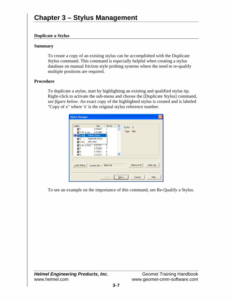
Chapter 3 – Stylus Management
Helmel Engineering Products, Inc. Geomet Training Handbookwww.helmel.com www.geomet-cmm-software.com
3-7
Duplicate a Stylus
Summary
To create a copy of an existing stylus can be accomplished with the DuplicateStylus command. This command is especially helpful when creating a stylusdatabase on manual friction style probing systems where the need to re-qualifymultiple positions are required.
Procedure
To duplicate a stylus, start by highlighting an existing and qualified stylus tip.Right-click to activate the sub-menu and choose the [Duplicate Stylus] command,see figure below. An exact copy of the highlighted stylus is created and is labeled"Copy of x" where 'x' is the original stylus reference number.
To see an example on the importance of this command, see Re-Qualify a Stylus.

Chapter 3 – Stylus Management
Helmel Engineering Products, Inc. Geomet Training Handbookwww.helmel.com www.geomet-cmm-software.com
3-8
Labeling Stylus
Labeling an individual stylus is helpful in identifying its unique characteristics. InGeomet, when a new stylus is qualified, and by default, is given the next availabletip number. This is not very helpful in describing the characteristic of the stylus.For example, the tip may be the "left tip" on a stylus cluster.
To attach a label on a single stylus, two methods can be employed. The firstinvolves the standard Windows interface where you highlight the desired tip byleft clicking once on the stylus under the Label column header. Then pause andleft-click on the stylus again, Windows acknowledges the second left-click, andan edit box surrounds the current label and you can type directly into the StylusManager list.
Should Windows not provide the edit label tool, you can activate the edit labeltool by selecting the stylus as described above and press the "l" <lowercase L>key on the keyboard. This will start the edit process for that selected stylus. Tocomplete the labeling processes, press the <Enter> key on the keyboard, orhighlight another stylus.
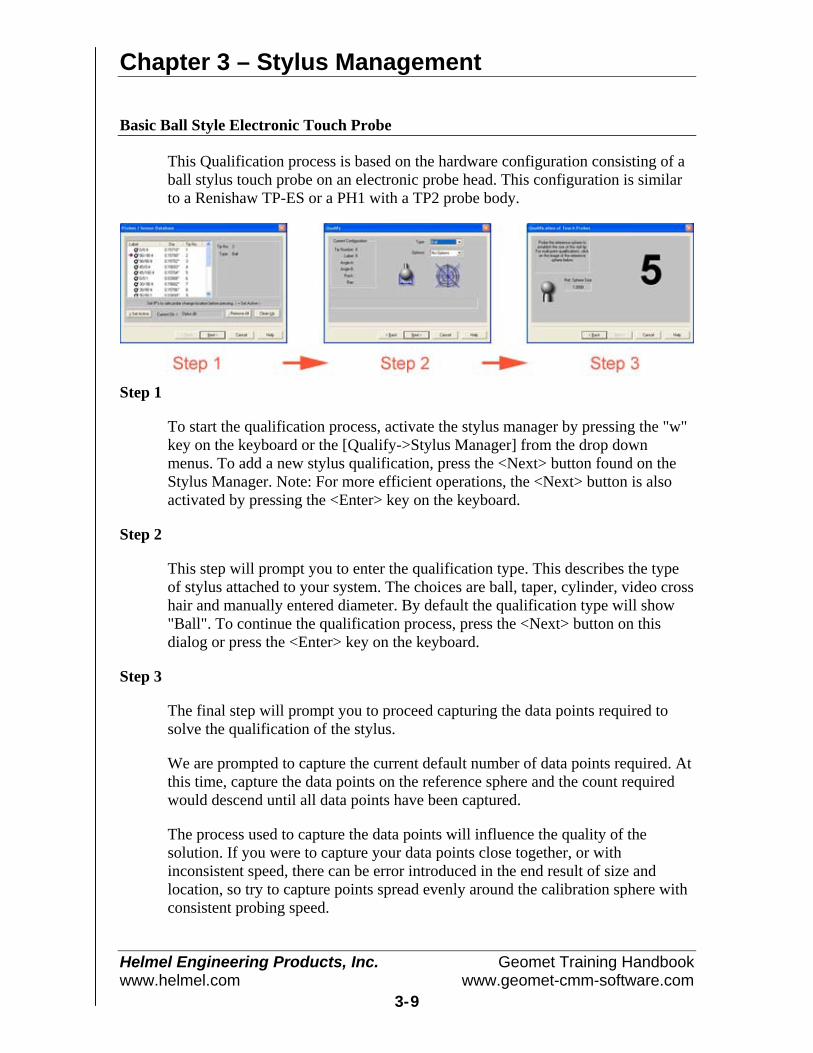
Chapter 3 – Stylus Management
Helmel Engineering Products, Inc. Geomet Training Handbookwww.helmel.com www.geomet-cmm-software.com
3-9
Basic Ball Style Electronic Touch Probe
This Qualification process is based on the hardware configuration consisting of aball stylus touch probe on an electronic probe head. This configuration is similarto a Renishaw TP-ES or a PH1 with a TP2 probe body.
Step 1
To start the qualification process, activate the stylus manager by pressing the "w"key on the keyboard or the [Qualify->Stylus Manager] from the drop downmenus. To add a new stylus qualification, press the <Next> button found on theStylus Manager. Note: For more efficient operations, the <Next> button is alsoactivated by pressing the <Enter> key on the keyboard.
Step 2
This step will prompt you to enter the qualification type. This describes the typeof stylus attached to your system. The choices are ball, taper, cylinder, video crosshair and manually entered diameter. By default the qualification type will show"Ball". To continue the qualification process, press the <Next> button on thisdialog or press the <Enter> key on the keyboard.
Step 3
The final step will prompt you to proceed capturing the data points required tosolve the qualification of the stylus.
We are prompted to capture the current default number of data points required. Atthis time, capture the data points on the reference sphere and the count requiredwould descend until all data points have been captured.
The process used to capture the data points will influence the quality of thesolution. If you were to capture your data points close together, or withinconsistent speed, there can be error introduced in the end result of size andlocation, so try to capture points spread evenly around the calibration sphere withconsistent probing speed.
Chapter 3 – Stylus Management
Helmel Engineering Products, Inc. Geomet Training Handbookwww.helmel.com www.geomet-cmm-software.com
3-10
We recommend that when using 5 data points, the first point should be taken onthe top of the reference sphere and the remaining 4 taken at the equator.
Should you require to abort a single data point that has been captured, press the<F2> key on the keyboard and the required count of data points will increase as itdiscards the last data point in the buffer.
Qualifying Ball Styli in Multiple Positions
This Qualification example is based on the hardware configuration consisting of aball stylus touch probe in different locations attached to one or more electronictouch probes. One example would be a manual articulating electronic probe headsuch as the Renishaw MIP. Another example would be a Cluster probe located onan electronic probe with multiple ball styli installed.
The process of qualifying more than one physical location involves the same stepsas described above in Basic Ball Style Electronic Touch Probe. The first probeshould be qualified exactly as stated in steps 1-3. When the first probe has beenqualified, you will return to the main screen of the Stylus Manager. To addanother position on a cluster, or another location on an articulating probe, followsteps 1-3 described above.
Geomet will qualify the MCS location and size and assign the next stylus tipnumber to the stylus database. The location it stores is the XYZ variation fromstylus tip number 1.
NOTE on Reference Sphere Location
On DCC style CMMs there is a "Home" position which is repeatable for inspectionresults. The MCS origin is the Home position of the CMM. This allows addingadditional stylus positions to the current stylus database without loss of position.
On manual CMMs that do not offer a Home procedure, the origin of the MCS is thelocation the CMM was at the time of power up, or the location when Geomet waslaunched. Therefore the origin position of the MCS is not reliable or repeatable.When you qualify multiple positions, all qualifications should be done during onesession to ensure correct relationships between all the stylus centers. Should youhave to add positions after a system restart, you should always clear your stylusdatabase and add all positions required for your inspection..
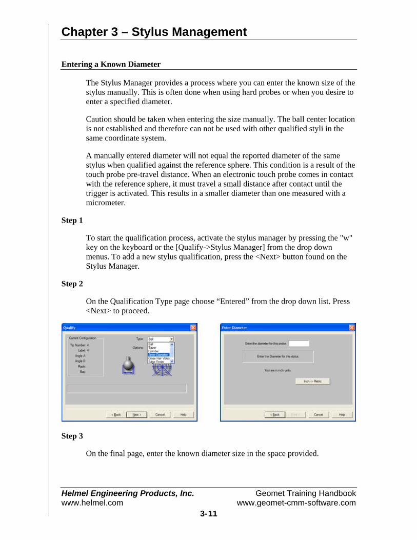
Chapter 3 – Stylus Management
Helmel Engineering Products, Inc. Geomet Training Handbookwww.helmel.com www.geomet-cmm-software.com
3-11
Entering a Known Diameter
The Stylus Manager provides a process where you can enter the known size of thestylus manually. This is often done when using hard probes or when you desire toenter a specified diameter.
Caution should be taken when entering the size manually. The ball center locationis not established and therefore can not be used with other qualified styli in thesame coordinate system.
A manually entered diameter will not equal the reported diameter of the samestylus when qualified against the reference sphere. This condition is a result of thetouch probe pre-travel distance. When an electronic touch probe comes in contactwith the reference sphere, it must travel a small distance after contact until thetrigger is activated. This results in a smaller diameter than one measured with amicrometer.
Step 1
To start the qualification process, activate the stylus manager by pressing the "w"key on the keyboard or the [Qualify->Stylus Manager] from the drop downmenus. To add a new stylus qualification, press the <Next> button found on theStylus Manager.
Step 2
On the Qualification Type page choose “Entered” from the drop down list. Press<Next> to proceed.
Step 3
On the final page, enter the known diameter size in the space provided.
Chapter 3 – Stylus Management
Helmel Engineering Products, Inc. Geomet Training Handbookwww.helmel.com www.geomet-cmm-software.com
3-12
Stylus Multiple Tip Relationships
To ensure accurate and repeatable inspections, it is important to understand therelationship between qualified stylus positions when you require more than one inyour inspection.
In your Stylus Database, the first stylus qualified is considered the primary orreference position for all qualified styli. The first qualification will record thecenter location in the MCS of the Reference Sphere and assign it to tip number 1.
All susequent qualifications will record the deviation to the primary tip. Thisallows Geomet to use multiple styli in a single coordinate system without a shiftin position. Geomet also allows the use of multiple styli when measuring a singlefeature such as a cylinder.
Therefore certain conditions must be met to allow safe requalifications andmodifications to the Stylus Database. The first rule is that any stylus can bedeleted, except stylus tip number 1. Should you delete stylus tip number 1, thenall styli should be removed and qualified again.
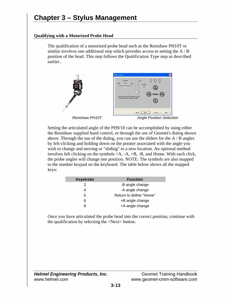
Chapter 3 – Stylus Management
Helmel Engineering Products, Inc. Geomet Training Handbookwww.helmel.com www.geomet-cmm-software.com
3-13
Qualifying with a Motorized Probe Head
The qualification of a motorized probe head such as the Renishaw PH10T orsimilar involves one additional step which provides access to setting the A / Bposition of the head. This step follows the Qualification Type step as describedearlier..
Renishaw PH10T Angle Position Selection
Setting the articulated angle of the PH9/10 can be accomplished by using eitherthe Renishaw supplied hand control, or through the use of Geomet's dialog shownabove. Through the use of the dialog, you can use the sliders for the A / B anglesby left-clicking and holding down on the pointer associated with the angle youwish to change and moving or "sliding" to a new location. An optional methodinvolves left clicking on the symbols +A, -A, +B, -B, and Home. With each click,the probe angles will change one position. NOTE: The symbols are also mappedto the number keypad on the keyboard. The table below shows all the mappedkeys:
Keystroke Function2 -B angle change4 -A angle change5 Return to define "Home"6 +B angle change8 +A angle change
Once you have articulated the probe head into the correct position, continue withthe qualification by selecting the <Next> button.
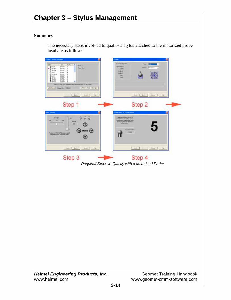
Chapter 3 – Stylus Management
Helmel Engineering Products, Inc. Geomet Training Handbookwww.helmel.com www.geomet-cmm-software.com
3-14
Summary
The necessary steps involved to qualify a stylus attached to the motorized probehead are as follows:
Required Steps to Qualify with a Motorized Probe

Chapter 3 – Stylus Management
Helmel Engineering Products, Inc. Geomet Training Handbookwww.helmel.com www.geomet-cmm-software.com
3-15
Qualifying with a Stylus Change Rack
The example provided here involves the use of a Stylus change rack such as theRenishaw MCR20 or SCR200 as shown in the figures below. The change rackallows the use of several stylus configurations that are magnetically attached tothe corresponding probe body. The use of the stylus change rack is controlledthrough the use of a graphical interface provided by Geomet to control thelocation and orientation of the rack in the MCS. The setup procedure of a stylusrack can be found in the [System Options->Probes and Sensors] page.
MCR 20 Stylus Change Rack SCR200 Stylus Change Rack

Chapter 3 – Stylus Management
Helmel Engineering Products, Inc. Geomet Training Handbookwww.helmel.com www.geomet-cmm-software.com
3-16
During the qualification process, Geomet will display a bay selection setup page,which instructs the operator to follow the necessary steps required to install amodule and qualify that position. This bay selection page is displayed after theQualification Type setup page, see Bay Selection.
Bay SelectionThe Bay Selection page can be expanded to show the current assignments byselecting the "Show Status" button. In left illustration, the graphic representationof the stylus rack shows no modules pre-loaded in the stylus rack and no moduleattached the probe. In right illustration, we see modules loaded in bay 1 and 5 anda module loaded on the probe body, which is identified as having the modulefrom Bay 1.
No Assignments Assigned Bays

Chapter 3 – Stylus Management
Helmel Engineering Products, Inc. Geomet Training Handbookwww.helmel.com www.geomet-cmm-software.com
3-17
During the qualification process, you are asked to identify the bay number usedfor the selected stylus. To select a bay, left-click on the bay location directly onthe graphic, or use the corresponding number key on the number pad on thekeyboard.
If you select an empty bay, Geomet will prompt you to install the probe moduleon the probe body. This is done manually and care should be exercised to alignthe module based on the symbols on the module and probe body. Once themodule has been installed, select the <Next> button which will proceed to thequalification page.
Should you select a bay that already has a module loaded, such as a module with astylus cluster attached to it, Geomet will proceed to the qualification page.
NOTE: If the module assigned to bay 1 is already installed on the probe when youselect bay 5 for qualification, Geomet will prompt you to unload the currentmodule and under DCC control will proceed to the safe staging area forinstallation of the new module.
Summary
The necessary steps involved to qualify a stylus attached to the stylus change rackare as follows:
Qualification Steps with Stylus Rack
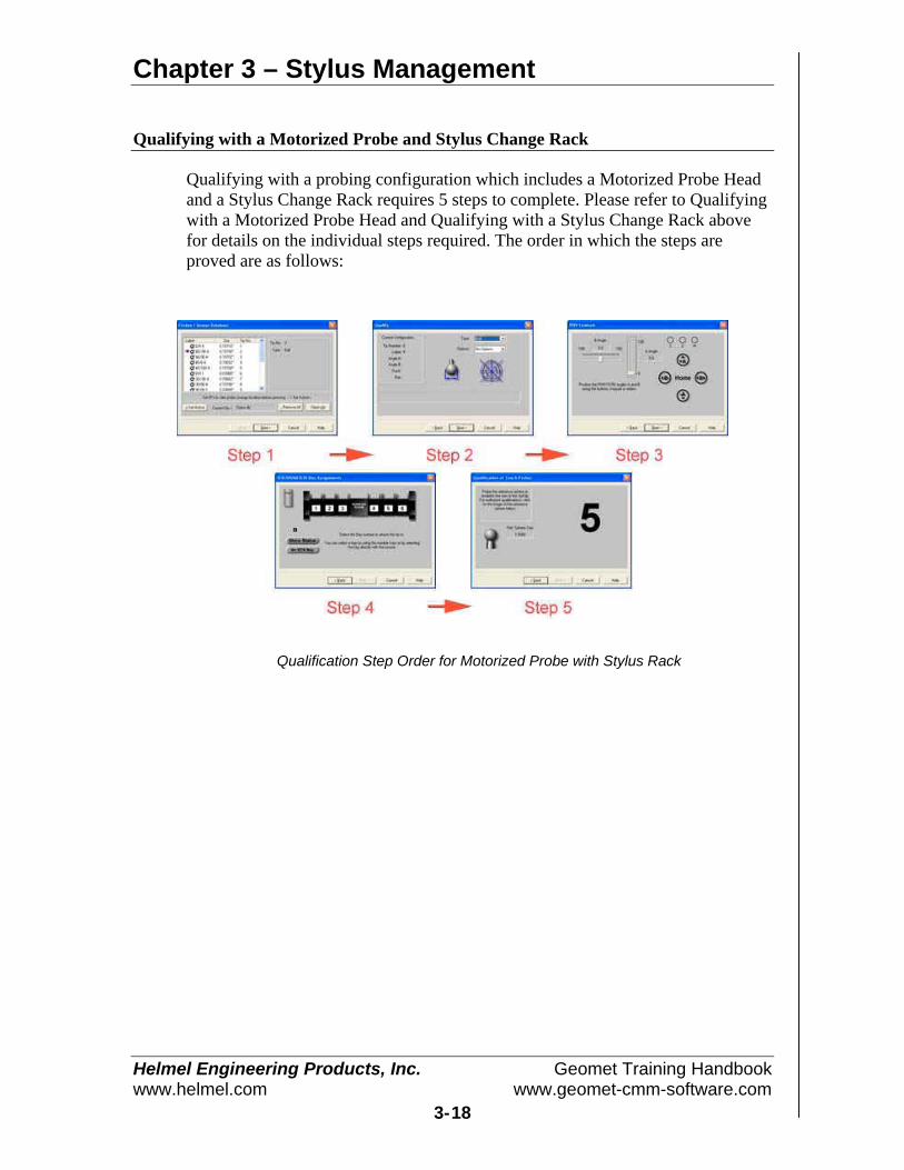
Chapter 3 – Stylus Management
Helmel Engineering Products, Inc. Geomet Training Handbookwww.helmel.com www.geomet-cmm-software.com
3-18
Qualifying with a Motorized Probe and Stylus Change Rack
Qualifying with a probing configuration which includes a Motorized Probe Headand a Stylus Change Rack requires 5 steps to complete. Please refer to Qualifyingwith a Motorized Probe Head and Qualifying with a Stylus Change Rack abovefor details on the individual steps required. The order in which the steps areproved are as follows:
Qualification Step Order for Motorized Probe with Stylus Rack

Chapter 3 – Stylus Management
Helmel Engineering Products, Inc. Geomet Training Handbookwww.helmel.com www.geomet-cmm-software.com
3-19
Stylus Db Manager
The Stylus db Manager provides tools to maintain more than 1 stylus database.Through the use of separate stylus database files, you can build specific stylusconfigurations based on your inspection needs and keep your stylus databasemanageable.
For example, it is not necessary to build one rather large stylus database thatcovers all your part inspections. It is also not efficient to clear out and build thestylus database with every unique part inspection. Therefore, Geomet canmaintain unique stylus database files assigned to each part inspection, group orfamily, for example.
The Stylus db Manager performs a test to a part program file when it is opened.This test looks for the original stylus database in use when the part program wascreated and compares it against the current stylus database in use.
The Stylus Db Manager is activated by:
Keyboard: Ctrl + Alt + w
Menu: Qualify->Stylus Db Manager
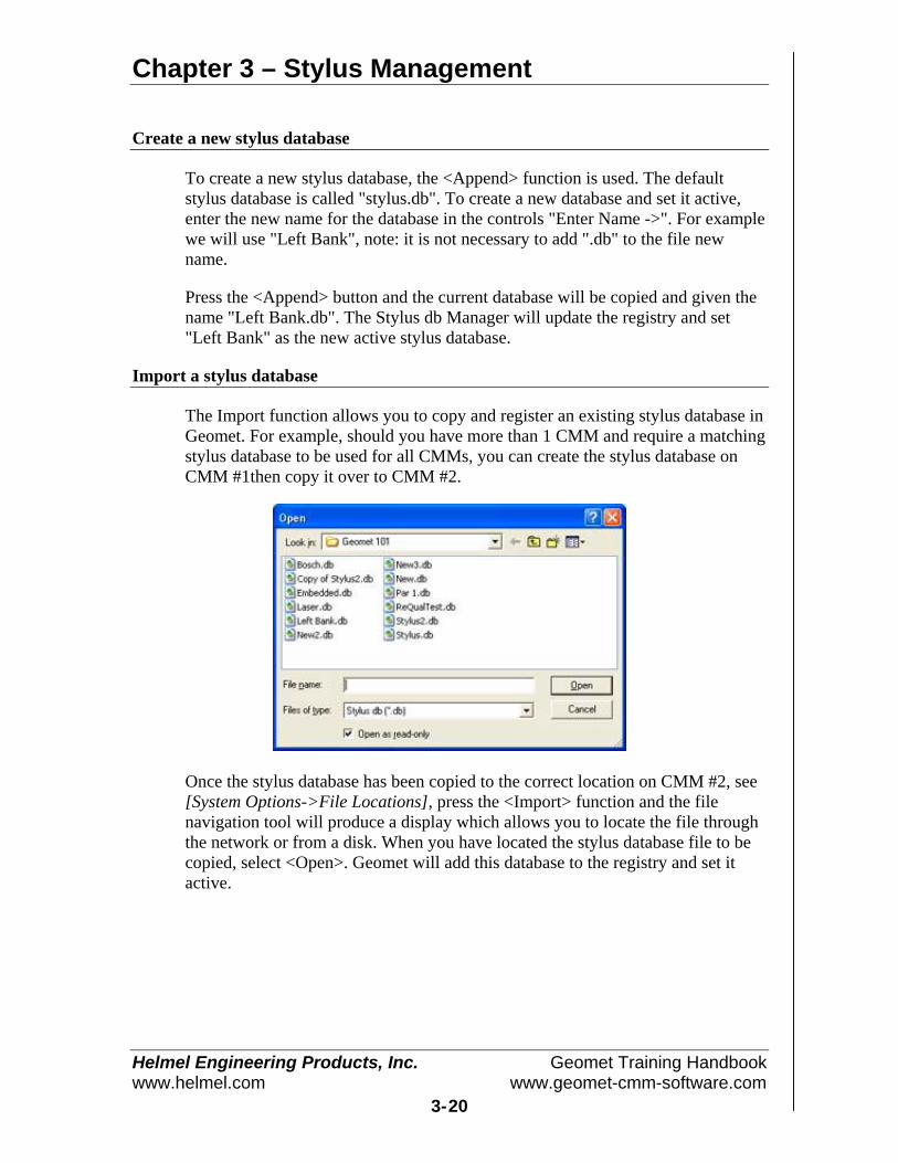
Chapter 3 – Stylus Management
Helmel Engineering Products, Inc. Geomet Training Handbookwww.helmel.com www.geomet-cmm-software.com
3-20
Create a new stylus database
To create a new stylus database, the <Append> function is used. The defaultstylus database is called "stylus.db". To create a new database and set it active,enter the new name for the database in the controls "Enter Name ->". For examplewe will use "Left Bank", note: it is not necessary to add ".db" to the file newname.
Press the <Append> button and the current database will be copied and given thename "Left Bank.db". The Stylus db Manager will update the registry and set"Left Bank" as the new active stylus database.
Import a stylus database
The Import function allows you to copy and register an existing stylus database inGeomet. For example, should you have more than 1 CMM and require a matchingstylus database to be used for all CMMs, you can create the stylus database onCMM #1then copy it over to CMM #2.
Once the stylus database has been copied to the correct location on CMM #2, see[System Options->File Locations], press the <Import> function and the filenavigation tool will produce a display which allows you to locate the file throughthe network or from a disk. When you have located the stylus database file to becopied, select <Open>. Geomet will add this database to the registry and set itactive.

Chapter 3 – Stylus Management
Helmel Engineering Products, Inc. Geomet Training Handbookwww.helmel.com www.geomet-cmm-software.com
3-21
Delete a Stylus Database Listing
The process of deleting a stylus database will remove the listing in the registry.This will not delete the actual file. Geomet will no longer see the file.
Selecting a stylus database
To delete a stylus database from use in Geomet, drop down the list of files in the"Existing Databases ->" control, see figure above. In this example, we will choose"New2". To complete the delete process, press the <Delete> button.
Should you try to delete the current stylus database in use, the Stylus db Managerwill default to "Stylus.db" as the new active stylus database.
Set active a Stylus Database
Use the Stylus Db Manager to select which stylus database is available to be used.To view the available database files, drop down the list of files in the "ExistingDatabases ->" control. Locate the database to be set active and press the <SetActive>. Geomet will now display and use the stylus configurations from this filein your inspection report.
When you change stylus databases it is a good practice to re-qualify the individualstylus tips. This should be done if you are not sure other changes have been madesuch as re-mounting the probe head or changing stylus tips associated withdifferent configurations of a particular stylus database.
NOTE: You should not switch the stylus database during a part inspection. Thiscan cause loss of accurate data.
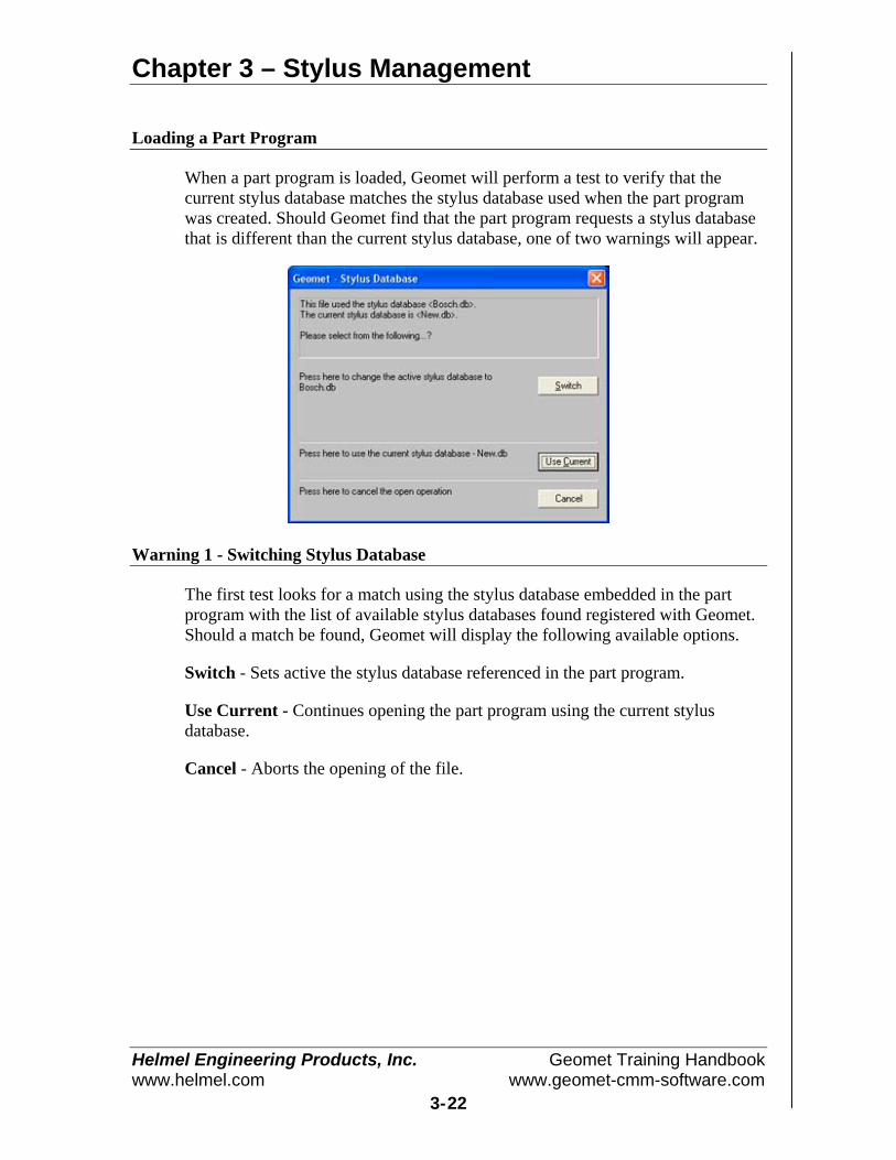
Chapter 3 – Stylus Management
Helmel Engineering Products, Inc. Geomet Training Handbookwww.helmel.com www.geomet-cmm-software.com
3-22
Loading a Part Program
When a part program is loaded, Geomet will perform a test to verify that thecurrent stylus database matches the stylus database used when the part programwas created. Should Geomet find that the part program requests a stylus databasethat is different than the current stylus database, one of two warnings will appear.
Warning 1 - Switching Stylus Database
The first test looks for a match using the stylus database embedded in the partprogram with the list of available stylus databases found registered with Geomet.Should a match be found, Geomet will display the following available options.
Switch - Sets active the stylus database referenced in the part program.
Use Current - Continues opening the part program using the current stylusdatabase.
Cancel - Aborts the opening of the file.
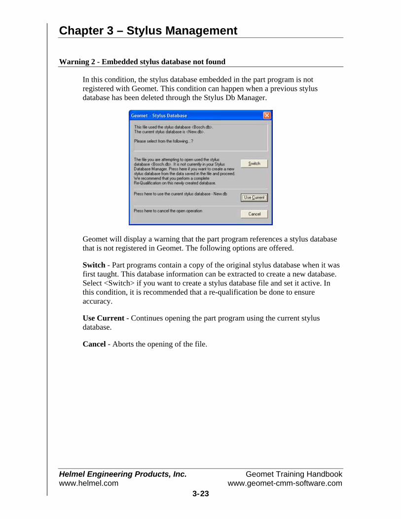
Chapter 3 – Stylus Management
Helmel Engineering Products, Inc. Geomet Training Handbookwww.helmel.com www.geomet-cmm-software.com
3-23
Warning 2 - Embedded stylus database not found
In this condition, the stylus database embedded in the part program is notregistered with Geomet. This condition can happen when a previous stylusdatabase has been deleted through the Stylus Db Manager.
Geomet will display a warning that the part program references a stylus databasethat is not registered in Geomet. The following options are offered.
Switch - Part programs contain a copy of the original stylus database when it wasfirst taught. This database information can be extracted to create a new database.Select <Switch> if you want to create a stylus database file and set it active. Inthis condition, it is recommended that a re-qualification be done to ensureaccuracy.
Use Current - Continues opening the part program using the current stylusdatabase.
Cancel - Aborts the opening of the file.
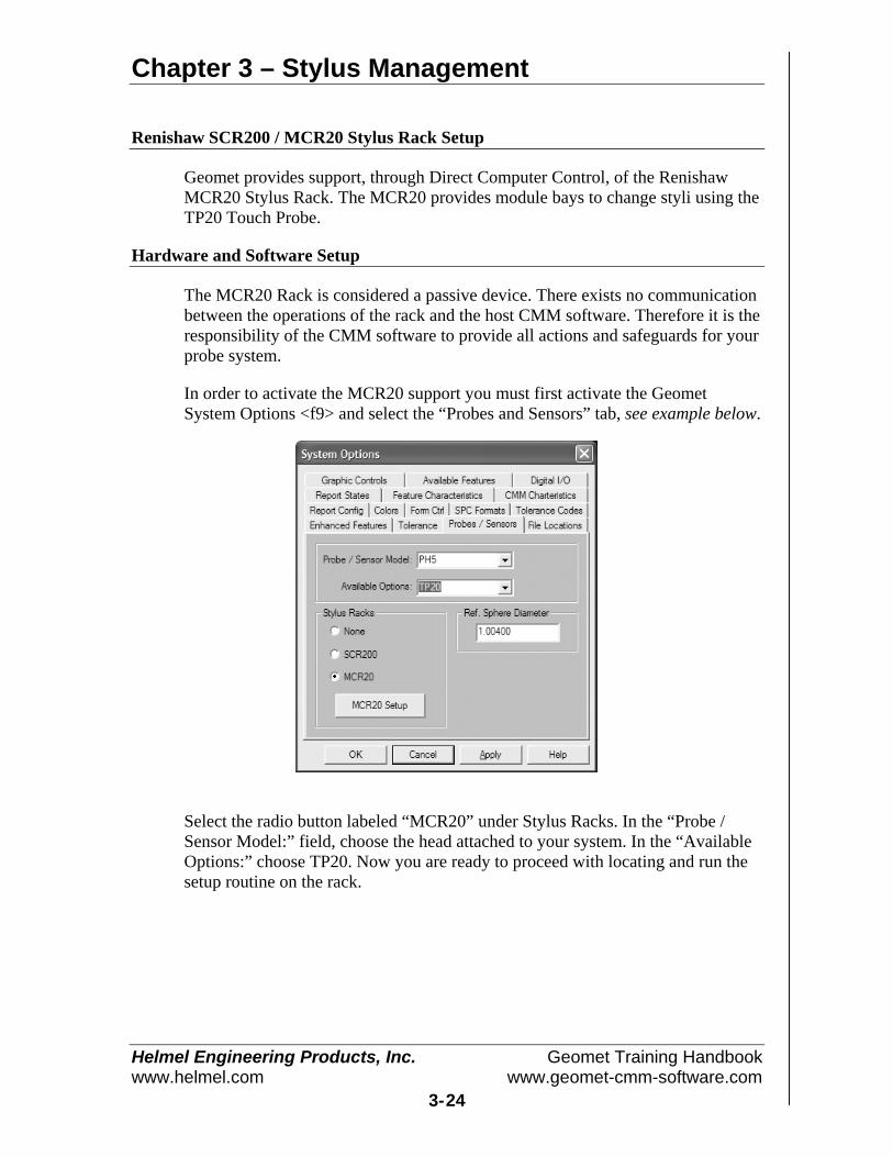
Chapter 3 – Stylus Management
Helmel Engineering Products, Inc. Geomet Training Handbookwww.helmel.com www.geomet-cmm-software.com
3-24
Renishaw SCR200 / MCR20 Stylus Rack Setup
Geomet provides support, through Direct Computer Control, of the RenishawMCR20 Stylus Rack. The MCR20 provides module bays to change styli using theTP20 Touch Probe.
Hardware and Software Setup
The MCR20 Rack is considered a passive device. There exists no communicationbetween the operations of the rack and the host CMM software. Therefore it is theresponsibility of the CMM software to provide all actions and safeguards for yourprobe system.
In order to activate the MCR20 support you must first activate the GeometSystem Options <f9> and select the “Probes and Sensors” tab, see example below.
Select the radio button labeled “MCR20” under Stylus Racks. In the “Probe /Sensor Model:” field, choose the head attached to your system. In the “AvailableOptions:” choose TP20. Now you are ready to proceed with locating and run thesetup routine on the rack.
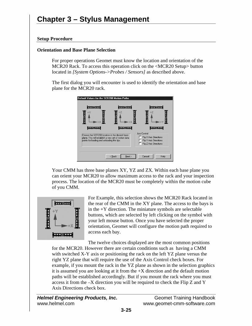
Chapter 3 – Stylus Management
Helmel Engineering Products, Inc. Geomet Training Handbookwww.helmel.com www.geomet-cmm-software.com
3-25
Setup Procedure
Orientation and Base Plane Selection
For proper operations Geomet must know the location and orientation of theMCR20 Rack. To access this operation click on the <MCR20 Setup> buttonlocated in [System Options->Probes / Sensors] as described above.
The first dialog you will encounter is used to identify the orientation and baseplane for the MCR20 rack.
Your CMM has three base planes XY, YZ and ZX. Within each base plane youcan orient your MCR20 to allow maximum access to the rack and your inspectionprocess. The location of the MCR20 must be completely within the motion cubeof you CMM.
For Example, this selection shows the MCR20 Rack located inthe rear of the CMM in the XY plane. The access to the bays isin the +Y direction. The miniature symbols are selectablebuttons, which are selected by left clicking on the symbol withyour left mouse button. Once you have selected the properorientation, Geomet will configure the motion path required toaccess each bay.
The twelve choices displayed are the most common positionsfor the MCR20. However there are certain conditions such as having a CMMwith switched X-Y axis or positioning the rack on the left YZ plane versus theright YZ plane that will require the use of the Axis Control check boxes. Forexample, if you mount the rack in the YZ plane as shown in the selection graphicsit is assumed you are looking at it from the +X direction and the default motionpaths will be established accordingly. But if you mount the rack where you mustaccess it from the –X direction you will be required to check the Flip Z and YAxis Directions check box.
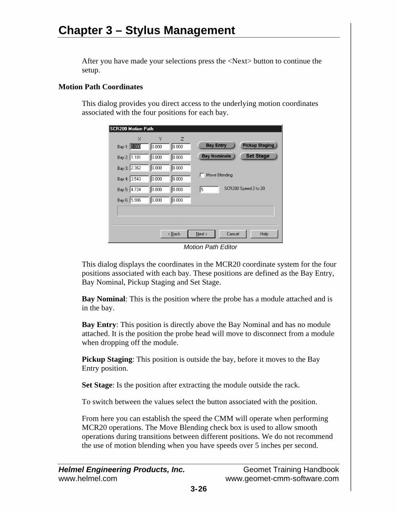
Chapter 3 – Stylus Management
Helmel Engineering Products, Inc. Geomet Training Handbookwww.helmel.com www.geomet-cmm-software.com
3-26
After you have made your selections press the <Next> button to continue thesetup.
Motion Path Coordinates
This dialog provides you direct access to the underlying motion coordinatesassociated with the four positions for each bay.
Motion Path Editor
This dialog displays the coordinates in the MCR20 coordinate system for the fourpositions associated with each bay. These positions are defined as the Bay Entry,Bay Nominal, Pickup Staging and Set Stage.
Bay Nominal: This is the position where the probe has a module attached and isin the bay.
Bay Entry: This position is directly above the Bay Nominal and has no moduleattached. It is the position the probe head will move to disconnect from a modulewhen dropping off the module.
Pickup Staging: This position is outside the bay, before it moves to the BayEntry position.
Set Stage: Is the position after extracting the module outside the rack.
To switch between the values select the button associated with the position.
From here you can establish the speed the CMM will operate when performingMCR20 operations. The Move Blending check box is used to allow smoothoperations during transitions between different positions. We do not recommendthe use of motion blending when you have speeds over 5 inches per second.
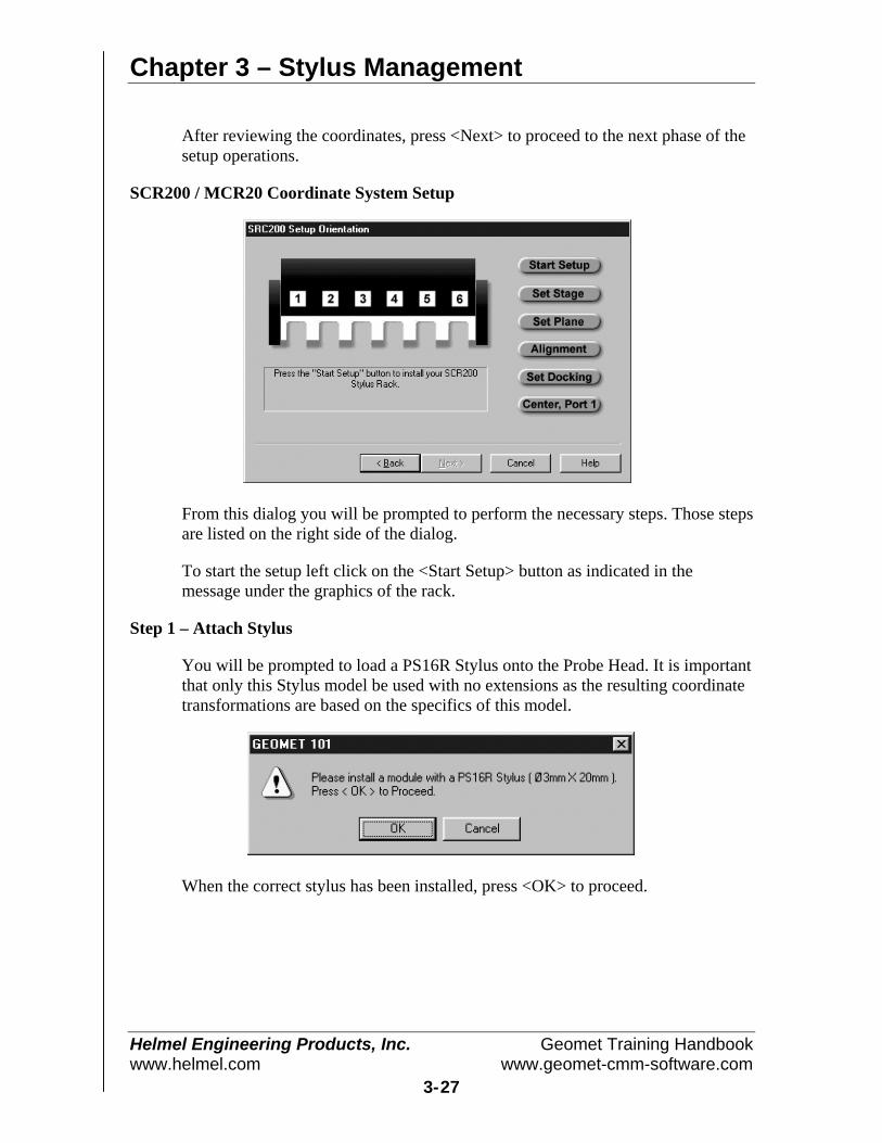
Chapter 3 – Stylus Management
Helmel Engineering Products, Inc. Geomet Training Handbookwww.helmel.com www.geomet-cmm-software.com
3-27
After reviewing the coordinates, press <Next> to proceed to the next phase of thesetup operations.
SCR200 / MCR20 Coordinate System Setup
From this dialog you will be prompted to perform the necessary steps. Those stepsare listed on the right side of the dialog.
To start the setup left click on the <Start Setup> button as indicated in themessage under the graphics of the rack.
Step 1 – Attach Stylus
You will be prompted to load a PS16R Stylus onto the Probe Head. It is importantthat only this Stylus model be used with no extensions as the resulting coordinatetransformations are based on the specifics of this model.
When the correct stylus has been installed, press <OK> to proceed.
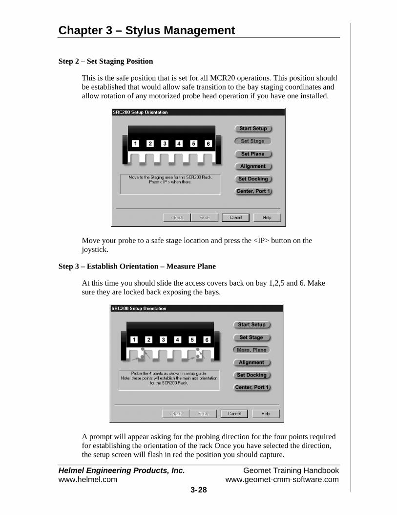
Chapter 3 – Stylus Management
Helmel Engineering Products, Inc. Geomet Training Handbookwww.helmel.com www.geomet-cmm-software.com
3-28
Step 2 – Set Staging Position
This is the safe position that is set for all MCR20 operations. This position shouldbe established that would allow safe transition to the bay staging coordinates andallow rotation of any motorized probe head operation if you have one installed.
Move your probe to a safe stage location and press the <IP> button on thejoystick.
Step 3 – Establish Orientation – Measure Plane
At this time you should slide the access covers back on bay 1,2,5 and 6. Makesure they are locked back exposing the bays.
A prompt will appear asking for the probing direction for the four points requiredfor establishing the orientation of the rack Once you have selected the direction,the setup screen will flash in red the position you should capture.
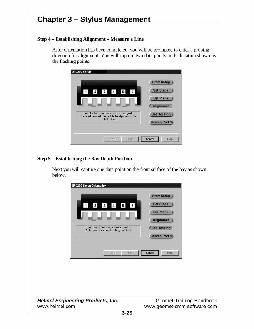
Chapter 3 – Stylus Management
Helmel Engineering Products, Inc. Geomet Training Handbookwww.helmel.com www.geomet-cmm-software.com
3-29
Step 4 – Establishing Alignment – Measure a Line
After Orientation has been completed, you will be prompted to enter a probingdirection for alignment. You will capture two data points in the location shown bythe flashing points.
Step 5 – Establishing the Bay Depth Position
Next you will capture one data point on the front surface of the bay as shownbelow.
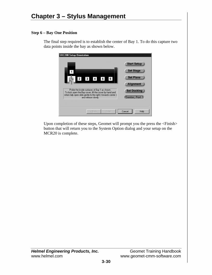
Chapter 3 – Stylus Management
Helmel Engineering Products, Inc. Geomet Training Handbookwww.helmel.com www.geomet-cmm-software.com
3-30
Step 6 – Bay One Position
The final step required is to establish the center of Bay 1. To do this capture twodata points inside the bay as shown below.
Upon completion of these steps, Geomet will prompt you the press the <Finish>button that will return you to the System Option dialog and your setup on theMCR20 is complete.

Chapter 3 – Stylus Management
Helmel Engineering Products, Inc. Geomet Training Handbookwww.helmel.com www.geomet-cmm-software.com
3-31
SCR200 / MCR20 Maintenance Operations
Geomet provides access to MCR20 though Maintenance Operations and theStylus Manager. Each method has unique capabilities in the operation of Geomet.
The Maintenance mode is primarily used to test the rack and change assignedlocations, clean styli or replace damaged styli. It is important that the modules arenot placed into the bays by hand. Each module must be aligned accurately toallow the probe head to reseat the module.
To start the Maintenance mode press the <Alt< + <w> keys on the keyboard.From this dialog you can control the operations of the MCR20 outside of partinspection programs.
This graphic shows a Touch Probe and the current status of themodule. The graphic on the left indicates that the moduleassigned to a bay number one is attached to the touch probe.The graphic on the right indicates that no module is attached tothe touch probe. You have the ability to change the moduleassignment by left clicking on the graphic of the touch probe,which will remove the module. Please note that this will not
perform the motion to park the module into the assigned bay, this will onlyremove it and its reference from Geomet.
This manual adjustment should only be used under certain conditions such asremoving all bay assignments.
The two buttons shown <Maintenance> and <Show Status> provide additionalfunctions when selected.
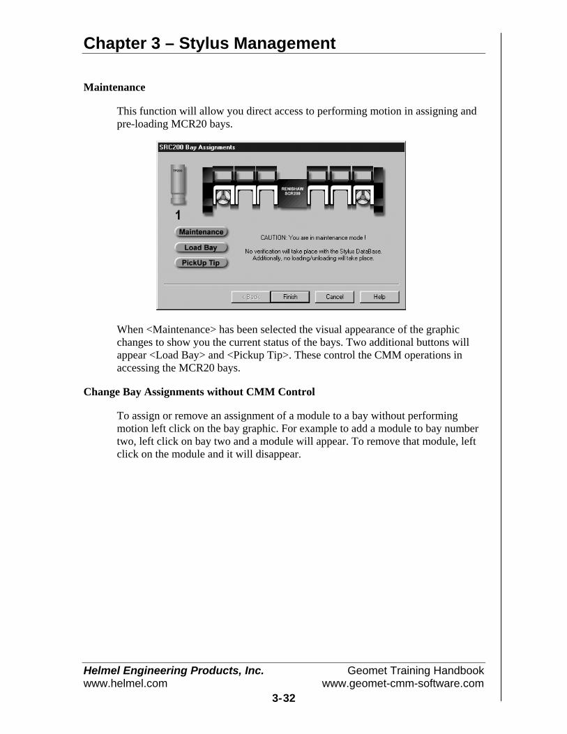
Chapter 3 – Stylus Management
Helmel Engineering Products, Inc. Geomet Training Handbookwww.helmel.com www.geomet-cmm-software.com
3-32
Maintenance
This function will allow you direct access to performing motion in assigning andpre-loading MCR20 bays.
When <Maintenance> has been selected the visual appearance of the graphicchanges to show you the current status of the bays. Two additional buttons willappear <Load Bay> and <Pickup Tip>. These control the CMM operations inaccessing the MCR20 bays.
Change Bay Assignments without CMM Control
To assign or remove an assignment of a module to a bay without performingmotion left click on the bay graphic. For example to add a module to bay numbertwo, left click on bay two and a module will appear. To remove that module, leftclick on the module and it will disappear.
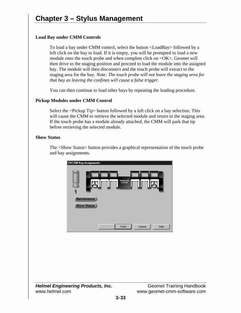
Chapter 3 – Stylus Management
Helmel Engineering Products, Inc. Geomet Training Handbookwww.helmel.com www.geomet-cmm-software.com
3-33
Load Bay under CMM Controls
To load a bay under CMM control, select the button <LoadBay> followed by aleft click on the bay to load. If it is empty, you will be prompted to load a newmodule onto the touch probe and when complete click on <OK>. Geomet willthen drive to the staging position and proceed to load the module into the assignedbay. The module will then disconnect and the touch probe will extract to thestaging area for the bay. Note: The touch probe will not leave the staging area forthat bay as leaving the confines will cause a false trigger.
You can then continue to load other bays by repeating the loading procedure.
Pickup Modules under CMM Control
Select the <Pickup Tip> button followed by a left click on a bay selection. Thiswill cause the CMM to retrieve the selected module and return to the staging area.If the touch probe has a module already attached, the CMM will park that tipbefore retrieving the selected module.
Show Status
The <Show Status> button provides a graphical representation of the touch probeand bay assignments.
Chapter 3 – Stylus Management
Helmel Engineering Products, Inc. Geomet Training Handbookwww.helmel.com www.geomet-cmm-software.com
3-34
NOTE on using the Maintenance ModesThese modes should be used with caution. It is primarily designed for theexperienced operator who wants to perform maintenance on installed modules suchas cleaning or replacing tips. The assigning of bays from this mode does not provideany means to qualify the styli or provide access to motorized probe heads such as thePH9.
It is not necessary to use this mode for populating and qualifying your styli. TheStylus Manager will handle all operations of assignments and qualifying your styli.
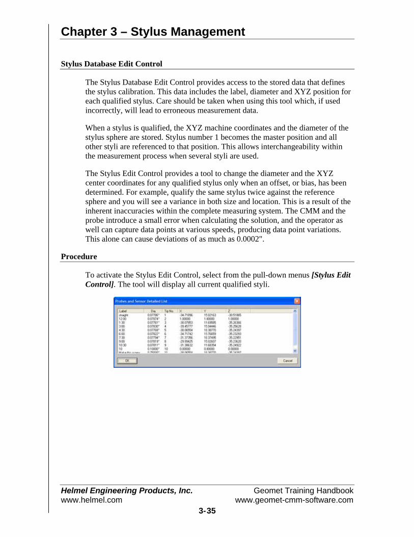
Chapter 3 – Stylus Management
Helmel Engineering Products, Inc. Geomet Training Handbookwww.helmel.com www.geomet-cmm-software.com
3-35
Stylus Database Edit Control
The Stylus Database Edit Control provides access to the stored data that definesthe stylus calibration. This data includes the label, diameter and XYZ position foreach qualified stylus. Care should be taken when using this tool which, if usedincorrectly, will lead to erroneous measurement data.
When a stylus is qualified, the XYZ machine coordinates and the diameter of thestylus sphere are stored. Stylus number 1 becomes the master position and allother styli are referenced to that position. This allows interchangeability withinthe measurement process when several styli are used.
The Stylus Edit Control provides a tool to change the diameter and the XYZcenter coordinates for any qualified stylus only when an offset, or bias, has beendetermined. For example, qualify the same stylus twice against the referencesphere and you will see a variance in both size and location. This is a result of theinherent inaccuracies within the complete measuring system. The CMM and theprobe introduce a small error when calculating the solution, and the operator aswell can capture data points at various speeds, producing data point variations.This alone can cause deviations of as much as 0.0002".
Procedure
To activate the Stylus Edit Control, select from the pull-down menus [Stylus EditControl]. The tool will display all current qualified styli.

Chapter 3 – Stylus Management
Helmel Engineering Products, Inc. Geomet Training Handbookwww.helmel.com www.geomet-cmm-software.com
3-36
To edit a selected stylus, select the stylus by left clicking on the entry in the list.When the selection has been made, a button labeled <Edit> will show.
Press the <Edit> button to change the label, size or position values.
There are two methods to change the position values for the Stylus. The firstmethod is a direct Machine Coordinate Value XYZ position. This is shown to theright of the label "Stylus MCS Position". The second option is to apply a relativeoffset value to the MCS position.
To make a relative change, enter the desired value of the change. For example, ifthe stylus tip #2 measures the location of a sphere consistently at X=0.0005, Y= -0.0002, Z=0.0003 relative to the same sphere measured with stylus tip #1, you canapply a correction factor to bring Stylus Tip #2 in-line with Stylus Tip #1. EnterX=-0.0005, Y=0.0002, Z=-0.0003 in the "Relative Position Adjustment" controls.Apply the change by pressing <Apply Rel. Adjustment>.
When you have finished, press the <Update> button to make the changes, or<Cancel Changes> to return to the list without saving the changes. To update thestylus database, save your changes by pressing the <Ok>. To cancel all changesmade, press the <Cancel> button.

Chapter 4 – Feature Measurement
Helmel Engineering Products, Inc. Geomet Training Handbookwww.helmel.com www.geomet-cmm-software.com
4-1
Chapter 4 – Feature Measurement
Basic FeaturesPoint ................................................................................................... 4-2
1D Point ....................................................................................... 4-3Auto Direction Sensing and 1D Points ........................................ 4-42D Point ....................................................................................... 4-5Inside Radial / Outside Radial 2D Point ...................................... 4-63D Point ....................................................................................... 4-7Inside Radial / Outside Radial 3D Point ...................................... 4-7Vector Point ................................................................................. 4-8Understanding Vector Points ....................................................... 4-9Vector Point Technical Discussion............................................ 4-11Vector Point Report Format....................................................... 4-12Vector Point, XYZ/IJK Known ................................................. 4-13Vector Point Unknown Data...................................................... 4-16Vector Point IJK Known............................................................ 4-18Vector Point XYZ Known ......................................................... 4-19Vector Point Import File ............................................................ 4-21
Line .................................................................................................. 4-34
Circle................................................................................................ 4-37
Plane................................................................................................. 4-39Upper / Lower Boundary Plane ................................................. 4-41
Sphere .............................................................................................. 4-43
Cylinder ........................................................................................... 4-44
Cone ................................................................................................. 4-46Cone Offset ................................................................................ 4-47Cone Diameter ........................................................................... 4-48Cone Drop Ball Test .................................................................. 4-49
Macro Features4 Point Intersect ......................................................................... 4-50Slot/Web .................................................................................... 4-51Oval Slot .................................................................................... 4-52
Feature Averaging............................................................................ 4-54
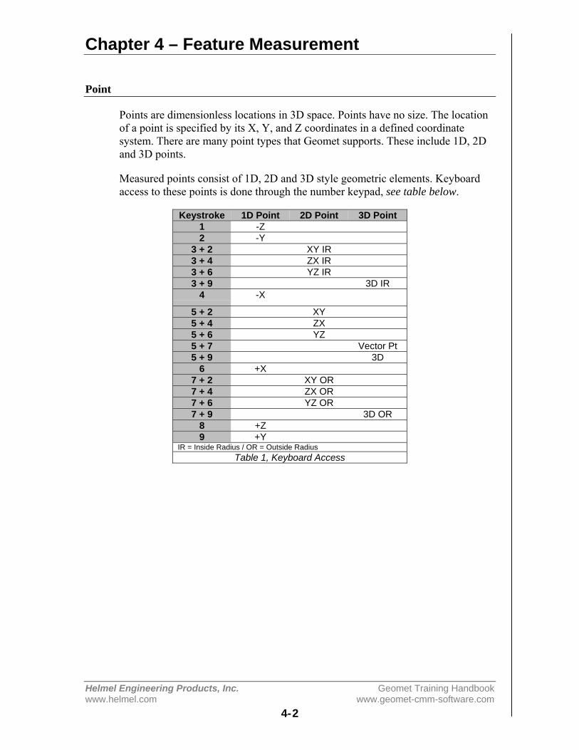
Chapter 4 – Feature Measurement
Helmel Engineering Products, Inc. Geomet Training Handbookwww.helmel.com www.geomet-cmm-software.com
4-2
Point
Points are dimensionless locations in 3D space. Points have no size. The locationof a point is specified by its X, Y, and Z coordinates in a defined coordinatesystem. There are many point types that Geomet supports. These include 1D, 2Dand 3D points.
Measured points consist of 1D, 2D and 3D style geometric elements. Keyboardaccess to these points is done through the number keypad, see table below.
Keystroke 1D Point 2D Point 3D Point1 -Z2 -Y
3 + 2 XY IR3 + 4 ZX IR3 + 6 YZ IR3 + 9 3D IR
4 -X
5 + 2 XY5 + 4 ZX5 + 6 YZ5 + 7 Vector Pt5 + 9 3D
6 +X7 + 2 XY OR7 + 4 ZX OR7 + 6 YZ OR7 + 9 3D OR
8 +Z9 +Y
IR = Inside Radius / OR = Outside RadiusTable 1, Keyboard Access
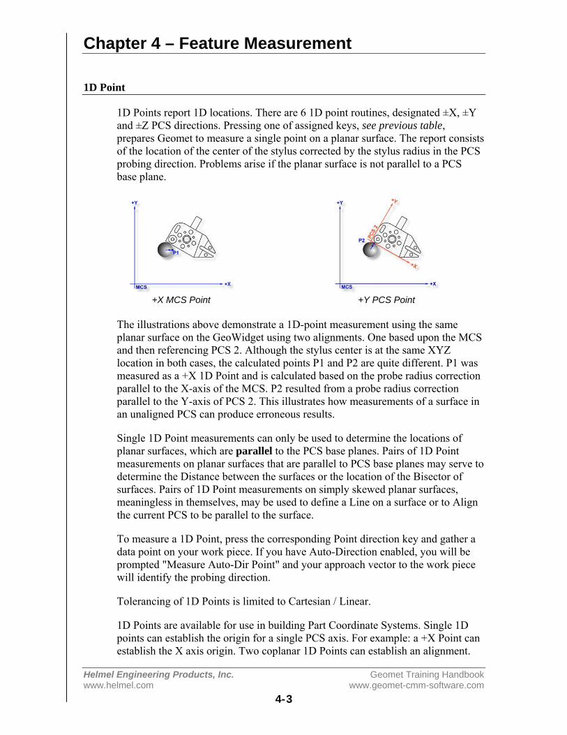
Chapter 4 – Feature Measurement
Helmel Engineering Products, Inc. Geomet Training Handbookwww.helmel.com www.geomet-cmm-software.com
4-3
1D Point
1D Points report 1D locations. There are 6 1D point routines, designated ±X, ±Yand ±Z PCS directions. Pressing one of assigned keys, see previous table,prepares Geomet to measure a single point on a planar surface. The report consistsof the location of the center of the stylus corrected by the stylus radius in the PCSprobing direction. Problems arise if the planar surface is not parallel to a PCSbase plane.
+X MCS Point +Y PCS Point
The illustrations above demonstrate a 1D-point measurement using the sameplanar surface on the GeoWidget using two alignments. One based upon the MCSand then referencing PCS 2. Although the stylus center is at the same XYZlocation in both cases, the calculated points P1 and P2 are quite different. P1 wasmeasured as a +X 1D Point and is calculated based on the probe radius correctionparallel to the X-axis of the MCS. P2 resulted from a probe radius correctionparallel to the Y-axis of PCS 2. This illustrates how measurements of a surface inan unaligned PCS can produce erroneous results.
Single 1D Point measurements can only be used to determine the locations ofplanar surfaces, which are parallel to the PCS base planes. Pairs of 1D Pointmeasurements on planar surfaces that are parallel to PCS base planes may serve todetermine the Distance between the surfaces or the location of the Bisector ofsurfaces. Pairs of 1D Point measurements on simply skewed planar surfaces,meaningless in themselves, may be used to define a Line on a surface or to Alignthe current PCS to be parallel to the surface.
To measure a 1D Point, press the corresponding Point direction key and gather adata point on your work piece. If you have Auto-Direction enabled, you will beprompted "Measure Auto-Dir Point" and your approach vector to the work piecewill identify the probing direction.
Tolerancing of 1D Points is limited to Cartesian / Linear.
1D Points are available for use in building Part Coordinate Systems. Single 1Dpoints can establish the origin for a single PCS axis. For example: a +X Point canestablish the X axis origin. Two coplanar 1D Points can establish an alignment.

Chapter 4 – Feature Measurement
Helmel Engineering Products, Inc. Geomet Training Handbookwww.helmel.com www.geomet-cmm-software.com
4-4
Auto Direction Sensing and 1D PointsUsing auto direction on 1D Points can lead to erroneous reported values if usedincorrectly. Auto direction relies on a smooth approach, from you the operator, incapturing of a data point. The process of determining the approach vectorinvolves the CMM interface card (ProCounter, Tech 80 or PMAC) to maintain arolling IJK vector based on the last five reported values. These interface cardsupdate the current position in the MCS on a programmable time interval from 20to 200 milliseconds.
Auto Direction Approach Vector
When you are approaching your work piece, it is required that you make contactwhile remaining in a ±45° approach, see figure above. In this example, if weremained in the approach zone we will capture a data point that will be reportedas a +Y point. If the operator did not remain in the approach zone the 1D Pointmight report a + or - X Point from which we will have to correct the probecompensation error. Most common occurrence of a erroneous data point comesfrom operators who approach the surface, and then pause during the approach andattempt to make contact under extremely slow speeds, which while approachingcauses variations in the path toward the surface.
To correct the reported direction of a 1D Point, highlight the feature by leftclicking on it, then right-click to bring up the feature menu, as shown in the figureon the next page. Select [Point Direction], which will offer a sub-menu with allsix probing directions available. Choose the correct 1D Point direction and yourpart inspection will update with the correct 1D Point.
Note: Once a feature has been referenced it can not be changed or edited. Forexample, if a feature was used in the construction of a PCS , it will be lockedfrom changes. This is identified by the inclusion of a ¹ next to the feature number,example " 12¹ ".
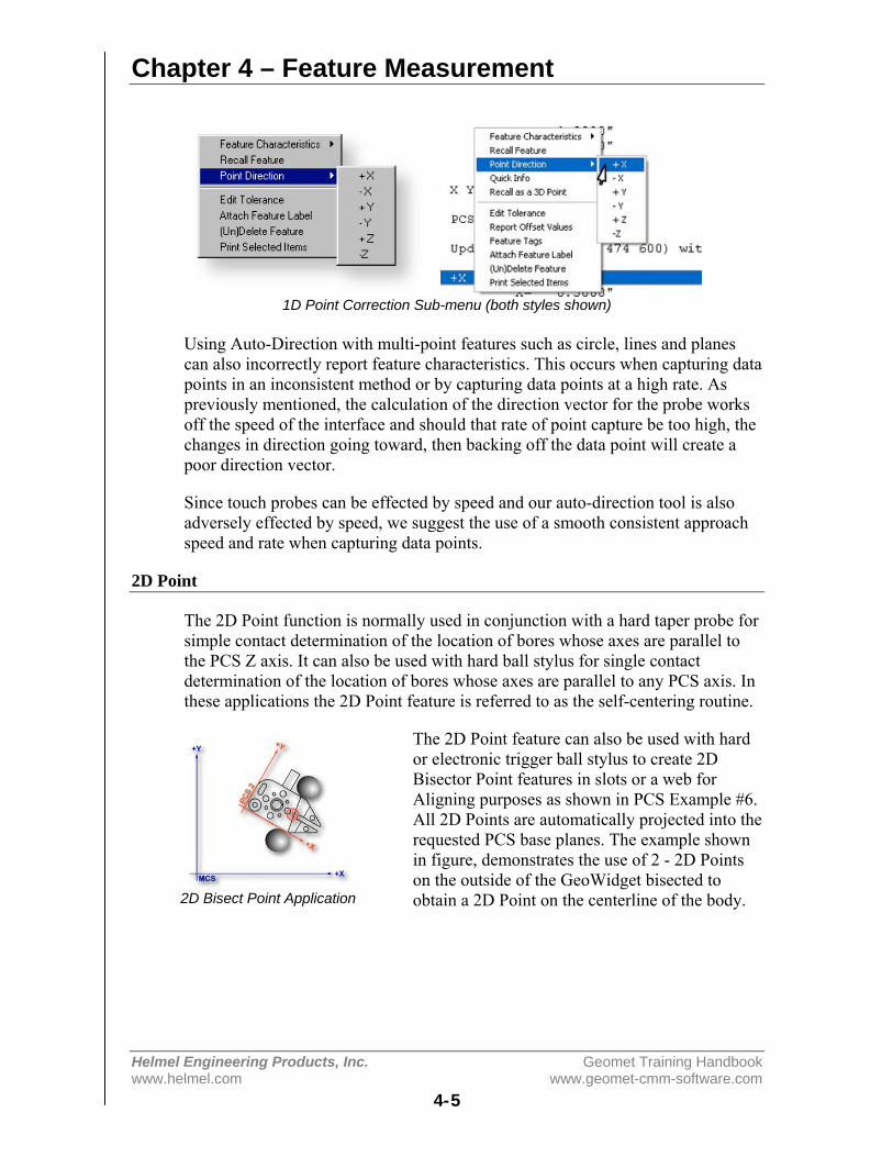
Chapter 4 – Feature Measurement
Helmel Engineering Products, Inc. Geomet Training Handbookwww.helmel.com www.geomet-cmm-software.com
4-5
1D Point Correction Sub-menu (both styles shown)
Using Auto-Direction with multi-point features such as circle, lines and planescan also incorrectly report feature characteristics. This occurs when capturing datapoints in an inconsistent method or by capturing data points at a high rate. Aspreviously mentioned, the calculation of the direction vector for the probe worksoff the speed of the interface and should that rate of point capture be too high, thechanges in direction going toward, then backing off the data point will create apoor direction vector.
Since touch probes can be effected by speed and our auto-direction tool is alsoadversely effected by speed, we suggest the use of a smooth consistent approachspeed and rate when capturing data points.
2D Point
The 2D Point function is normally used in conjunction with a hard taper probe forsimple contact determination of the location of bores whose axes are parallel tothe PCS Z axis. It can also be used with hard ball stylus for single contactdetermination of the location of bores whose axes are parallel to any PCS axis. Inthese applications the 2D Point feature is referred to as the self-centering routine.
The 2D Point feature can also be used with hardor electronic trigger ball stylus to create 2DBisector Point features in slots or a web forAligning purposes as shown in PCS Example #6.All 2D Points are automatically projected into therequested PCS base planes. The example shownin figure, demonstrates the use of 2 - 2D Pointson the outside of the GeoWidget bisected toobtain a 2D Point on the centerline of the body.2D Bisect Point Application
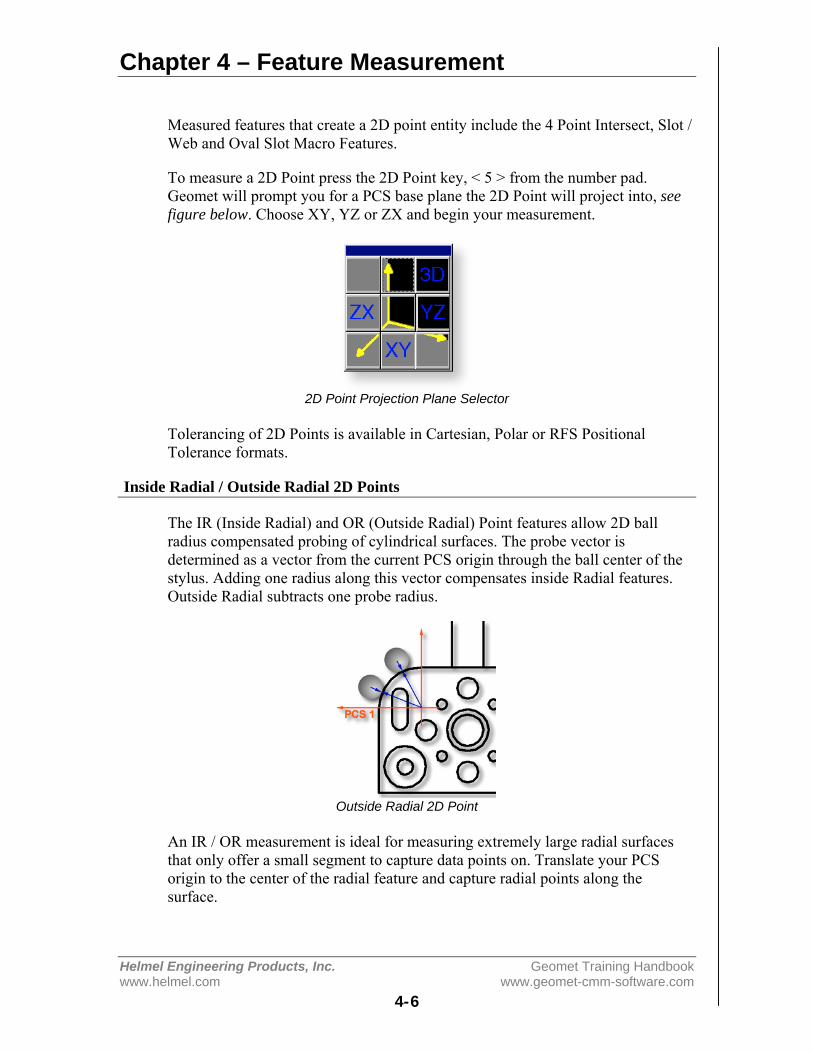
Chapter 4 – Feature Measurement
Helmel Engineering Products, Inc. Geomet Training Handbookwww.helmel.com www.geomet-cmm-software.com
4-6
Measured features that create a 2D point entity include the 4 Point Intersect, Slot /Web and Oval Slot Macro Features.
To measure a 2D Point press the 2D Point key, < 5 > from the number pad.Geomet will prompt you for a PCS base plane the 2D Point will project into, seefigure below. Choose XY, YZ or ZX and begin your measurement.
2D Point Projection Plane Selector
Tolerancing of 2D Points is available in Cartesian, Polar or RFS PositionalTolerance formats.
Inside Radial / Outside Radial 2D Points
The IR (Inside Radial) and OR (Outside Radial) Point features allow 2D ballradius compensated probing of cylindrical surfaces. The probe vector isdetermined as a vector from the current PCS origin through the ball center of thestylus. Adding one radius along this vector compensates inside Radial features.Outside Radial subtracts one probe radius.
Outside Radial 2D Point
An IR / OR measurement is ideal for measuring extremely large radial surfacesthat only offer a small segment to capture data points on. Translate your PCSorigin to the center of the radial feature and capture radial points along thesurface.
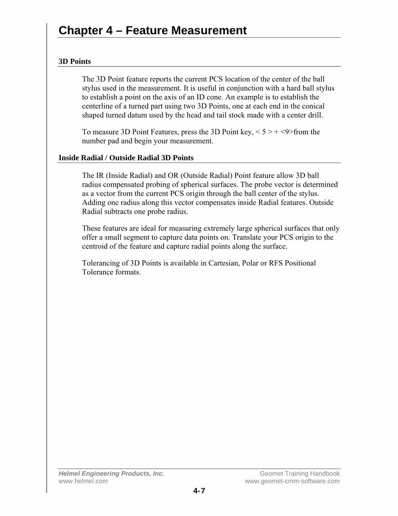
Chapter 4 – Feature Measurement
Helmel Engineering Products, Inc. Geomet Training Handbookwww.helmel.com www.geomet-cmm-software.com
4-7
3D Points
The 3D Point feature reports the current PCS location of the center of the ballstylus used in the measurement. It is useful in conjunction with a hard ball stylusto establish a point on the axis of an ID cone. An example is to establish thecenterline of a turned part using two 3D Points, one at each end in the conicalshaped turned datum used by the head and tail stock made with a center drill.
To measure 3D Point Features, press the 3D Point key, < 5 > + <9>from thenumber pad and begin your measurement.
Inside Radial / Outside Radial 3D Points
The IR (Inside Radial) and OR (Outside Radial) Point feature allow 3D ballradius compensated probing of spherical surfaces. The probe vector is determinedas a vector from the current PCS origin through the ball center of the stylus.Adding one radius along this vector compensates inside Radial features. OutsideRadial subtracts one probe radius.
These features are ideal for measuring extremely large spherical surfaces that onlyoffer a small segment to capture data points on. Translate your PCS origin to thecentroid of the feature and capture radial points along the surface.
Tolerancing of 3D Points is available in Cartesian, Polar or RFS PositionalTolerance formats.

Chapter 4 – Feature Measurement
Helmel Engineering Products, Inc. Geomet Training Handbookwww.helmel.com www.geomet-cmm-software.com
4-8
Vector Points
A Vector Point provides the capability to measure the deviation from nominal of atarget point on any arbitrary surface, given the XYZ location of the 3D target andthe nominal unit vector components I, I, and K at the target.
Geomet Vector Point Modes
Geomet offers several modes to capture Vector Points. Each mode is designed toenhance your ability to capture surface data points from all or some known data.These methods are:
• Method 1 - No nominal are known• Method 2 - IJK Normal Vector is known• Method 3 - XYZ Nominal Target is known• Method 4 - XYZ Nominal Target and IJK Normal Vector are known• Method 5 - Vector Point Import
To activate the Vector Point screen, press the <5> + <7> keystroke on the numberkeypad.
Vector Point Dialog – Manual CMM Operations
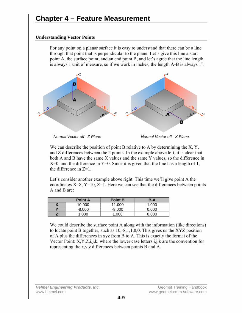
Chapter 4 – Feature Measurement
Helmel Engineering Products, Inc. Geomet Training Handbookwww.helmel.com www.geomet-cmm-software.com
4-9
Understanding Vector Points
For any point on a planar surface it is easy to understand that there can be a linethrough that point that is perpendicular to the plane. Let’s give this line a startpoint A, the surface point, and an end point B, and let’s agree that the line lengthis always 1 unit of measure, so if we work in inches, the length A-B is always 1”.
Normal Vector off –Z Plane Normal Vector off –X Plane
We can describe the position of point B relative to A by determining the X, Y,and Z differences between the 2 points. In the example above left, it is clear thatboth A and B have the same X values and the same Y values, so the difference inX=0, and the difference in Y=0. Since it is given that the line has a length of 1,the difference in Z=1.
Let’s consider another example above right. This time we’ll give point A thecoordinates X=8, Y=10, Z=1. Here we can see that the differences between pointsA and B are:
Point A Point B B-AX 10.000 11.000 1.000Y -8.000 -8.000 0.000Z 1.000 1.000 0.000
We could describe the surface point A along with the information (like directions)to locate point B together, such as 10,-8,1,1,0,0. This gives us the XYZ positionof A plus the differences in xyz from B to A. This is exactly the format of theVector Point: X,Y,Z,i,j,k, where the lower case letters i,j,k are the convention forrepresenting the x,y,z differences between points B and A.
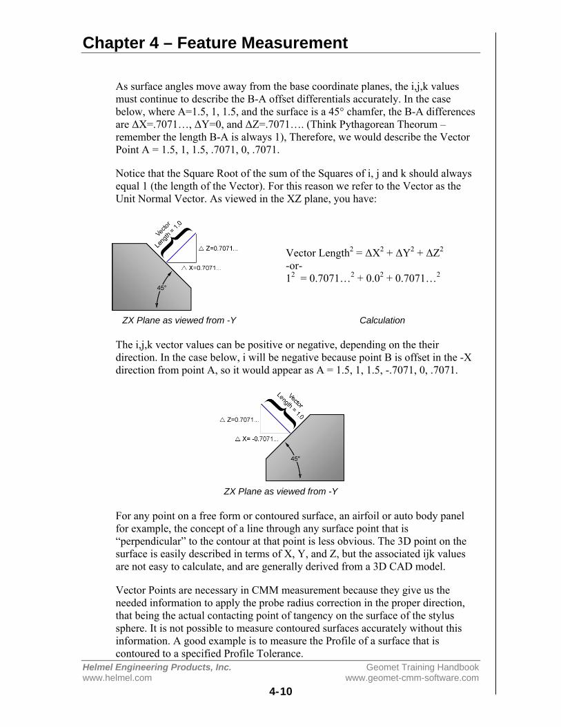
Chapter 4 – Feature Measurement
Helmel Engineering Products, Inc. Geomet Training Handbookwww.helmel.com www.geomet-cmm-software.com
4-10
As surface angles move away from the base coordinate planes, the i,j,k valuesmust continue to describe the B-A offset differentials accurately. In the casebelow, where A=1.5, 1, 1.5, and the surface is a 45° chamfer, the B-A differencesare ΔX=.7071…, ΔY=0, and ΔZ=.7071…. (Think Pythagorean Theorum –remember the length B-A is always 1), Therefore, we would describe the VectorPoint A = 1.5, 1, 1.5, .7071, 0, .7071.
Notice that the Square Root of the sum of the Squares of i, j and k should alwaysequal 1 (the length of the Vector). For this reason we refer to the Vector as theUnit Normal Vector. As viewed in the XZ plane, you have:
Vector Length2 = ΔX2 + ΔY2 + ΔZ2
-or-12 = 0.7071…2 + 0.02 + 0.7071…2
ZX Plane as viewed from -Y Calculation
The i,j,k vector values can be positive or negative, depending on the theirdirection. In the case below, i will be negative because point B is offset in the -Xdirection from point A, so it would appear as A = 1.5, 1, 1.5, -.7071, 0, .7071.
ZX Plane as viewed from -Y
For any point on a free form or contoured surface, an airfoil or auto body panelfor example, the concept of a line through any surface point that is“perpendicular” to the contour at that point is less obvious. The 3D point on thesurface is easily described in terms of X, Y, and Z, but the associated ijk valuesare not easy to calculate, and are generally derived from a 3D CAD model.
Vector Points are necessary in CMM measurement because they give us theneeded information to apply the probe radius correction in the proper direction,that being the actual contacting point of tangency on the surface of the stylussphere. It is not possible to measure contoured surfaces accurately without thisinformation. A good example is to measure the Profile of a surface that iscontoured to a specified Profile Tolerance.

Chapter 4 – Feature Measurement
Helmel Engineering Products, Inc. Geomet Training Handbookwww.helmel.com www.geomet-cmm-software.com
4-11
Geomet provides tools when necessary to determine the ijk values for any surfacepoint, for example, when they are not available from other sources. By measuringa small local plane around a designated surface point, a satisfactory estimation ofthe vector angles can be derived for that point. Geomet DCC does thisautomatically.
Vector Point Technical Discussion
To better understand the application of Vector Points, please refer to TechnicalNote #1, "Curved Surface Measurement with Vector Point".
While the percentage of Geomet users who have made extensive use of the vectorpoint function is small, some have come to regard it as indispensable, and everynow and then another Geomet owner discovers the wonders of vector point.Invariably, this discovery is followed by about two weeks of daily and lengthyphone conversations between the user and our application support engineers,during which the workings and benefits of the function gradually become clearerto the user. In an attempt to shorten this process, we have written a TechnicalNote, "Curved Surface Measurement with Vector Point", that contains adescription of its workings and some suggested experiments that might be used togain familiarity with the problems of curved surface measurement on a manualCMM. This technical note is long and likely boring for anyone without a seriousinterest in the problem.
Should your interest in vector point survive the reading of that technical note, youmay also be interested in learning Methods 1,2,3 and 5 in the Vector Pointchapters on the following pages. These methods detail the process used to create aworking solution to capture large vector point data clouds on complex surfaces.
Tolerancing of Vector Points is available in Cartesian, Polar or RFS PositionalTolerance formats.
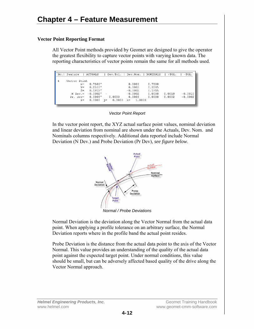
Chapter 4 – Feature Measurement
Helmel Engineering Products, Inc. Geomet Training Handbookwww.helmel.com www.geomet-cmm-software.com
4-12
Vector Point Reporting Format
All Vector Point methods provided by Geomet are designed to give the operatorthe greatest flexibility to capture vector points with varying known data. Thereporting characteristics of vector points remain the same for all methods used.
Vector Point Report
In the vector point report, the XYZ actual surface point values, nominal deviationand linear deviation from nominal are shown under the Actuals, Dev. Nom. andNominals columns respectively. Additional data reported include NormalDeviation (N Dev.) and Probe Deviation (Pr Dev), see figure below.
Normal / Probe Deviations
Normal Deviation is the deviation along the Vector Normal from the actual datapoint. When applying a profile tolerance on an arbitrary surface, the NormalDeviation reports where in the profile band the actual point resides.
Probe Deviation is the distance from the actual data point to the axis of the VectorNormal. This value provides an understanding of the quality of the actual datapoint against the expected target point. Under normal conditions, this valueshould be small, but can be adversely affected based quality of the drive along theVector Normal approach.

Chapter 4 – Feature Measurement
Helmel Engineering Products, Inc. Geomet Training Handbookwww.helmel.com www.geomet-cmm-software.com
4-13
Using Vector Point Tools
To begin, we will start with Method 4, where the XYZ Nominal Target and theIJK Normal Vector are known.
This method requires that you know the XYZ target and the IJK surface vectornormal at that target point. In our examples, we will utilize a 1" diameterreference sphere. Start by establishing an XYZ Origin on the center of the sphere.Utilize the orient and alignment of the MCS by creating a PCS with theICS⇒PCS function.
Manual CMM application of Method 4
Step 1
Enter the nominal XYZ target and the IJK normal vector values, see example.
Enter XYZ / IJK Values
Step 2
Press the <Ok> button or press the <enter> key on the keyboard. The TargetPositioning dialog will show where the probe is currently in relationship to wherethe probe should be to capture the vector point.
Target Window (XY are in Red) Target Window on Target (XY are in Green)
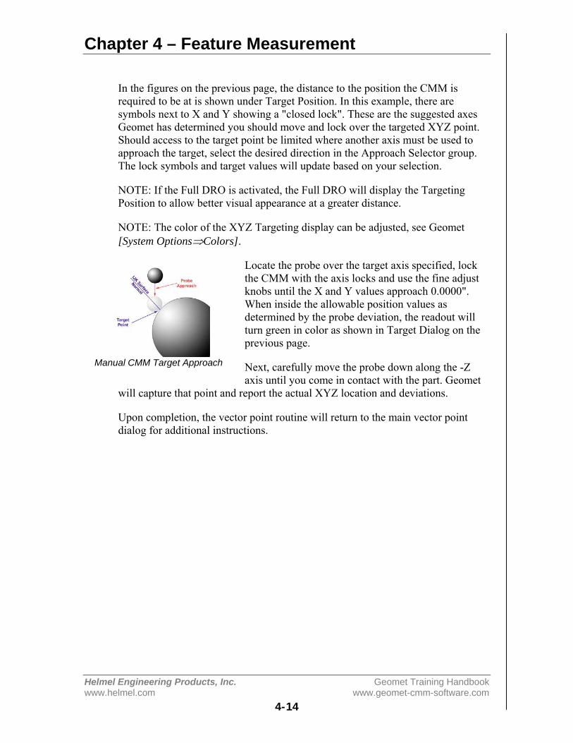
Chapter 4 – Feature Measurement
Helmel Engineering Products, Inc. Geomet Training Handbookwww.helmel.com www.geomet-cmm-software.com
4-14
In the figures on the previous page, the distance to the position the CMM isrequired to be at is shown under Target Position. In this example, there aresymbols next to X and Y showing a "closed lock". These are the suggested axesGeomet has determined you should move and lock over the targeted XYZ point.Should access to the target point be limited where another axis must be used toapproach the target, select the desired direction in the Approach Selector group.The lock symbols and target values will update based on your selection.
NOTE: If the Full DRO is activated, the Full DRO will display the TargetingPosition to allow better visual appearance at a greater distance.
NOTE: The color of the XYZ Targeting display can be adjusted, see Geomet[System Options⇒Colors].
Locate the probe over the target axis specified, lockthe CMM with the axis locks and use the fine adjustknobs until the X and Y values approach 0.0000".When inside the allowable position values asdetermined by the probe deviation, the readout willturn green in color as shown in Target Dialog on theprevious page.
Next, carefully move the probe down along the -Zaxis until you come in contact with the part. Geomet
will capture that point and report the actual XYZ location and deviations.
Upon completion, the vector point routine will return to the main vector pointdialog for additional instructions.
Manual CMM Target Approach

Chapter 4 – Feature Measurement
Helmel Engineering Products, Inc. Geomet Training Handbookwww.helmel.com www.geomet-cmm-software.com
4-15
DCC CMM application of Method 4
Step 1
Vector Point, DCC Version Enter XYZ / IJK Values
Enter the nominal XYZ target and the IJK normal vector values.
Step 2
DCC Target Dialog DCC Approach VectorPress the <Ok> or <AutoRun> button or press the <enter> key on the keyboard.The Target Positioning dialog will show where the probe is currently inrelationship to where the probe should be to capture the vector point.
Move the CMM teaching IPs until you are over the expected Stand Off, SO, onthe approach vector. Press the <AutoRun> button and the CMM will repositionover the expected target point along the IJK surface normal vector at the standofflocation. When at the stand off location the probe will commence to capture thevector point driving down the surface normal vector.
NOTE: The accuracy of moving along the approach vector is greatly influencedby the speed of approach and length of approach. To obtain the greatest control, itis better to have a slower approach speed, which is controlled by the probingspeed and is set in the DCC Options page. To increase the approach distance, thevalue can be set on the Vector Point main page.
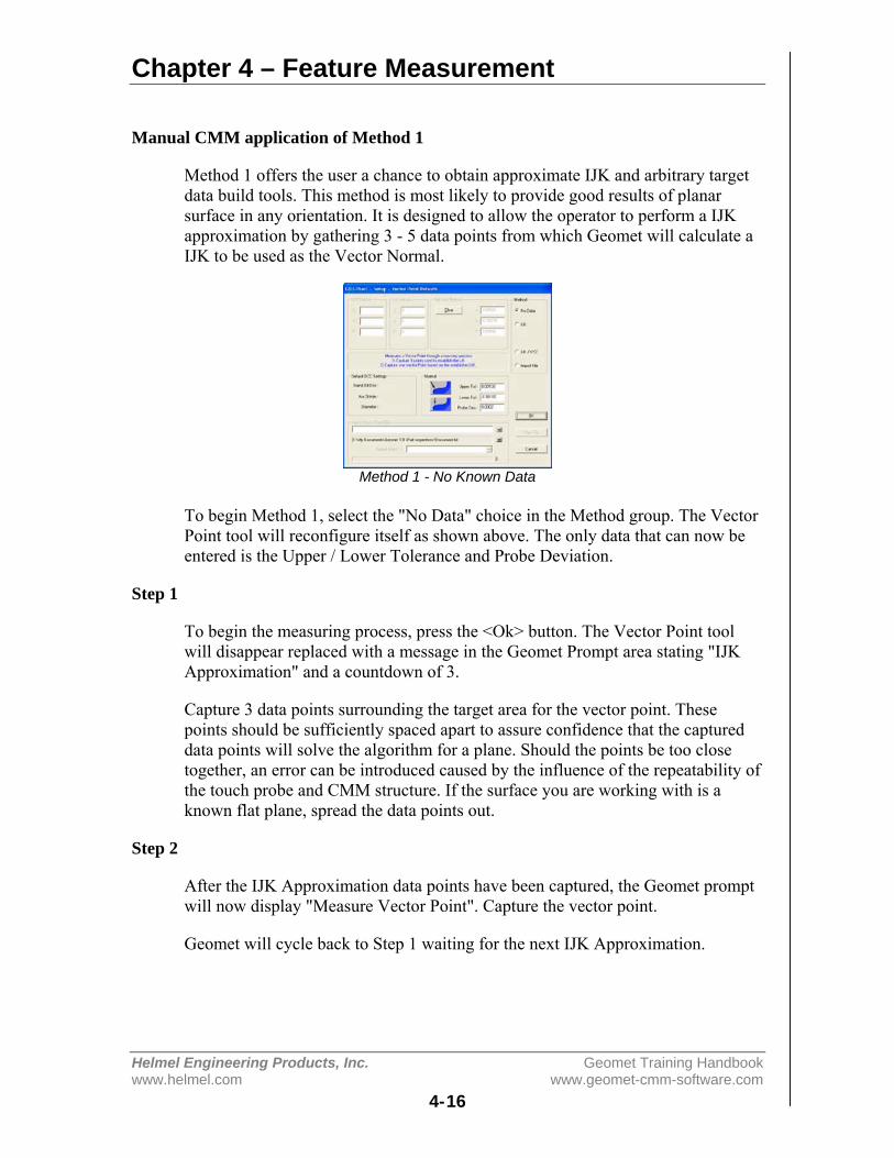
Chapter 4 – Feature Measurement
Helmel Engineering Products, Inc. Geomet Training Handbookwww.helmel.com www.geomet-cmm-software.com
4-16
Manual CMM application of Method 1
Method 1 offers the user a chance to obtain approximate IJK and arbitrary targetdata build tools. This method is most likely to provide good results of planarsurface in any orientation. It is designed to allow the operator to perform a IJKapproximation by gathering 3 - 5 data points from which Geomet will calculate aIJK to be used as the Vector Normal.
Method 1 - No Known Data
To begin Method 1, select the "No Data" choice in the Method group. The VectorPoint tool will reconfigure itself as shown above. The only data that can now beentered is the Upper / Lower Tolerance and Probe Deviation.
Step 1
To begin the measuring process, press the <Ok> button. The Vector Point toolwill disappear replaced with a message in the Geomet Prompt area stating "IJKApproximation" and a countdown of 3.
Capture 3 data points surrounding the target area for the vector point. Thesepoints should be sufficiently spaced apart to assure confidence that the captureddata points will solve the algorithm for a plane. Should the points be too closetogether, an error can be introduced caused by the influence of the repeatability ofthe touch probe and CMM structure. If the surface you are working with is aknown flat plane, spread the data points out.
Step 2
After the IJK Approximation data points have been captured, the Geomet promptwill now display "Measure Vector Point". Capture the vector point.
Geomet will cycle back to Step 1 waiting for the next IJK Approximation.

Chapter 4 – Feature Measurement
Helmel Engineering Products, Inc. Geomet Training Handbookwww.helmel.com www.geomet-cmm-software.com
4-17
DCC CMM application of Method 1
Performing Method 1 on a DCC style CMM offers a greater degree of accuracyon arbitrary surfaces. The process still requires an IJK Approximation thatbecomes a process that the CMM will perform.
DCC Method 1 Capture Target Point
Step 1
As seen in figure above, the Default DCC Settings group is available when theCMM is a DCC style. Enter a proper standoff distance for the vector point. Entera number of points to be used to determine the IJK Approximation in the controllabeled 'No. of Hits". Acceptable value for number of hits is 3 - 5. Enter adiameter value the CMM will use to capture the IJK Approximation points.Normally a small diameter such as 0.3" works well. Press the <Ok> button toproceed.
Step 2
The Vector Point Positioning dialog will appear. You are now instructed tocapture the target vector point on the surface.
Start Approximation Calculate Approximation Capture Vector Point
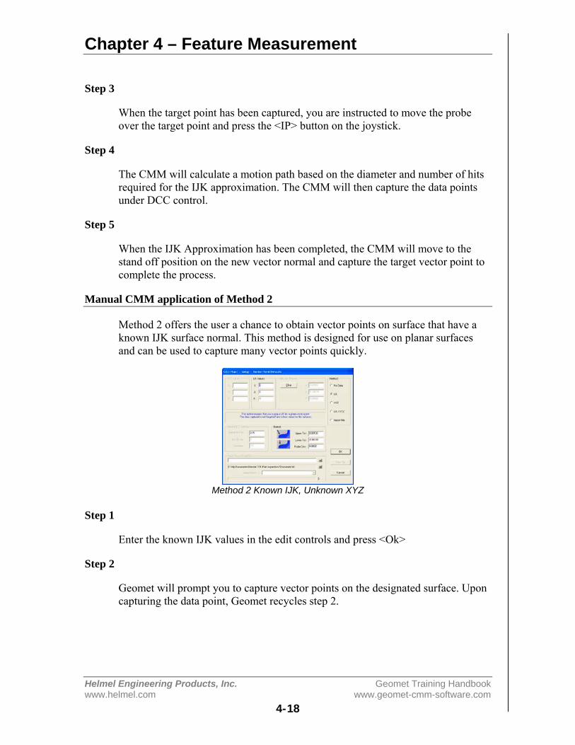
Chapter 4 – Feature Measurement
Helmel Engineering Products, Inc. Geomet Training Handbookwww.helmel.com www.geomet-cmm-software.com
4-18
Step 3
When the target point has been captured, you are instructed to move the probeover the target point and press the <IP> button on the joystick.
Step 4
The CMM will calculate a motion path based on the diameter and number of hitsrequired for the IJK approximation. The CMM will then capture the data pointsunder DCC control.
Step 5
When the IJK Approximation has been completed, the CMM will move to thestand off position on the new vector normal and capture the target vector point tocomplete the process.
Manual CMM application of Method 2
Method 2 offers the user a chance to obtain vector points on surface that have aknown IJK surface normal. This method is designed for use on planar surfacesand can be used to capture many vector points quickly.
Method 2 Known IJK, Unknown XYZ
Step 1
Enter the known IJK values in the edit controls and press <Ok>
Step 2
Geomet will prompt you to capture vector points on the designated surface. Uponcapturing the data point, Geomet recycles step 2.
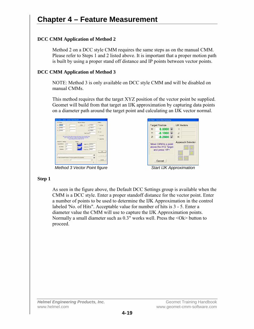
Chapter 4 – Feature Measurement
Helmel Engineering Products, Inc. Geomet Training Handbookwww.helmel.com www.geomet-cmm-software.com
4-19
DCC CMM Application of Method 2
Method 2 on a DCC style CMM requires the same steps as on the manual CMM.Please refer to Steps 1 and 2 listed above. It is important that a proper motion pathis built by using a proper stand off distance and IP points between vector points.
DCC CMM Application of Method 3
NOTE: Method 3 is only available on DCC style CMM and will be disabled onmanual CMMs.
This method requires that the target XYZ position of the vector point be supplied.Geomet will build from that target an IJK approximation by capturing data pointson a diameter path around the target point and calculating an IJK vector normal.
Method 3 Vector Point figure Start IJK Approximation
Step 1
As seen in the figure above, the Default DCC Settings group is available when theCMM is a DCC style. Enter a proper standoff distance for the vector point. Entera number of points to be used to determine the IJK Approximation in the controllabeled 'No. of Hits". Acceptable value for number of hits is 3 - 5. Enter adiameter value the CMM will use to capture the IJK Approximation points.Normally a small diameter such as 0.3" works well. Press the <Ok> button toproceed.
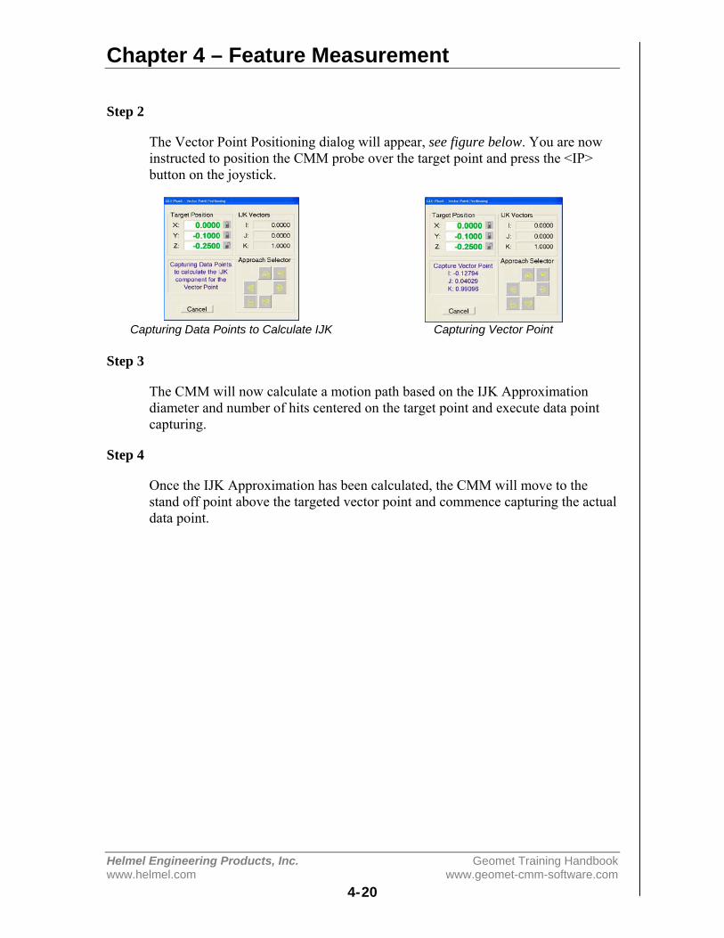
Chapter 4 – Feature Measurement
Helmel Engineering Products, Inc. Geomet Training Handbookwww.helmel.com www.geomet-cmm-software.com
4-20
Step 2
The Vector Point Positioning dialog will appear, see figure below. You are nowinstructed to position the CMM probe over the target point and press the <IP>button on the joystick.
Capturing Data Points to Calculate IJK Capturing Vector Point
Step 3
The CMM will now calculate a motion path based on the IJK Approximationdiameter and number of hits centered on the target point and execute data pointcapturing.
Step 4
Once the IJK Approximation has been calculated, the CMM will move to thestand off point above the targeted vector point and commence capturing the actualdata point.
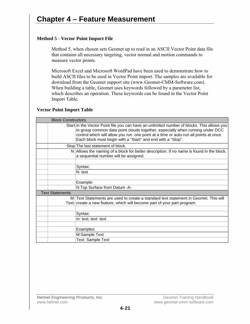
Chapter 4 – Feature Measurement
Helmel Engineering Products, Inc. Geomet Training Handbookwww.helmel.com www.geomet-cmm-software.com
4-21
Method 5 - Vector Point Import File
Method 5, when chosen sets Geomet up to read in an ASCII Vector Point data filethat contains all necessary targeting, vector normal and motion commands tomeasure vector points.
Microsoft Excel and Microsoft WordPad have been used to demonstrate how tobuild ASCII files to be used in Vector Point import. The samples are available fordownload from the Geomet support site (www.Geomet-CMM-Software.com).When building a table, Geomet uses keywords followed by a parameter list,which describes an operation. These keywords can be found in the Vector PointImport Table.
Vector Point Import Table
Block ConstructorsStart In the Vector Point file you can have an unlimited number of blocks. This allows you
to group common data point clouds together, especially when running under DCCcontrol which will allow you run one point at a time or auto-run all points at once.Each block must begin with a "Start" and end with a "Stop".
Stop The last statement of block.N: Allows the naming of a block for better description. If no name is found in the block,
a sequential number will be assigned.
Syntax:N: text
Example:N:Top Surface from Datum -A-
Text StatementsM:
Text:Text Statements are used to create a standard text statement in Geomet. This willcreate a new feature, which will become part of your part program.
Syntax:m: text, text: text
Examples:M:Sample TextText: Sample Text
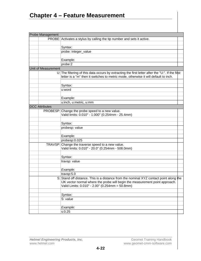
Chapter 4 – Feature Measurement
Helmel Engineering Products, Inc. Geomet Training Handbookwww.helmel.com www.geomet-cmm-software.com
4-22
Probe ManagementPROBE: Activates a stylus by calling the tip number and sets it active.
Syntax:probe: integer_value
Example:probe:2
Unit of MeasurementU: The filtering of this data occurs by extracting the first letter after the "U:". If the first
letter is a "m" then it switches to metric mode, otherwise it will default to inch.
Syntax:u:word
Example:u:inch, u:metric, u:mm
DCC AttributesPROBESP: Change the probe speed to a new value.
Valid limits: 0.010" - 1.000" (0.254mm - 25.4mm)
Syntax:probesp: value
Example:probesp:0.025
TRAVSP: Change the traverse speed to a new value.Valid limits: 0.010" - 20.0" (0.254mm - 508.0mm)
Syntax:travsp: value
Example:travsp:5.0
S: Stand off distance. This is a distance from the nominal XYZ contact point along theIJK vector normal where the probe will begin the measurement point approach.Valid Limits: 0.010" - 2.00" (0.254mm = 50.8mm)
Syntax:S: value
Example:s:0.25
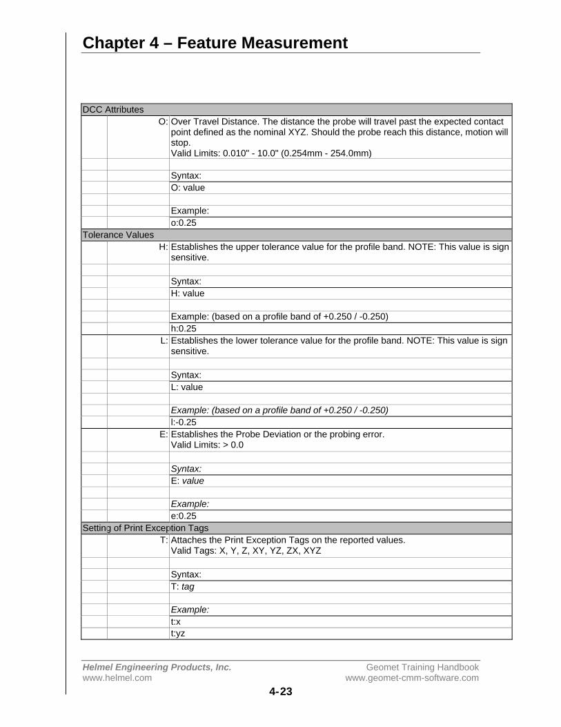
Chapter 4 – Feature Measurement
Helmel Engineering Products, Inc. Geomet Training Handbookwww.helmel.com www.geomet-cmm-software.com
4-23
DCC AttributesO: Over Travel Distance. The distance the probe will travel past the expected contact
point defined as the nominal XYZ. Should the probe reach this distance, motion willstop.Valid Limits: 0.010" - 10.0" (0.254mm - 254.0mm)
Syntax:O: value
Example:o:0.25
Tolerance ValuesH: Establishes the upper tolerance value for the profile band. NOTE: This value is sign
sensitive.
Syntax:H: value
Example: (based on a profile band of +0.250 / -0.250)h:0.25
L: Establishes the lower tolerance value for the profile band. NOTE: This value is signsensitive.
Syntax:L: value
Example: (based on a profile band of +0.250 / -0.250)l:-0.25
E: Establishes the Probe Deviation or the probing error.Valid Limits: > 0.0
Syntax:E: value
Example:e:0.25
Setting of Print Exception TagsT: Attaches the Print Exception Tags on the reported values.
Valid Tags: X, Y, Z, XY, YZ, ZX, XYZ
Syntax:T: tag
Example:t:xt:yz
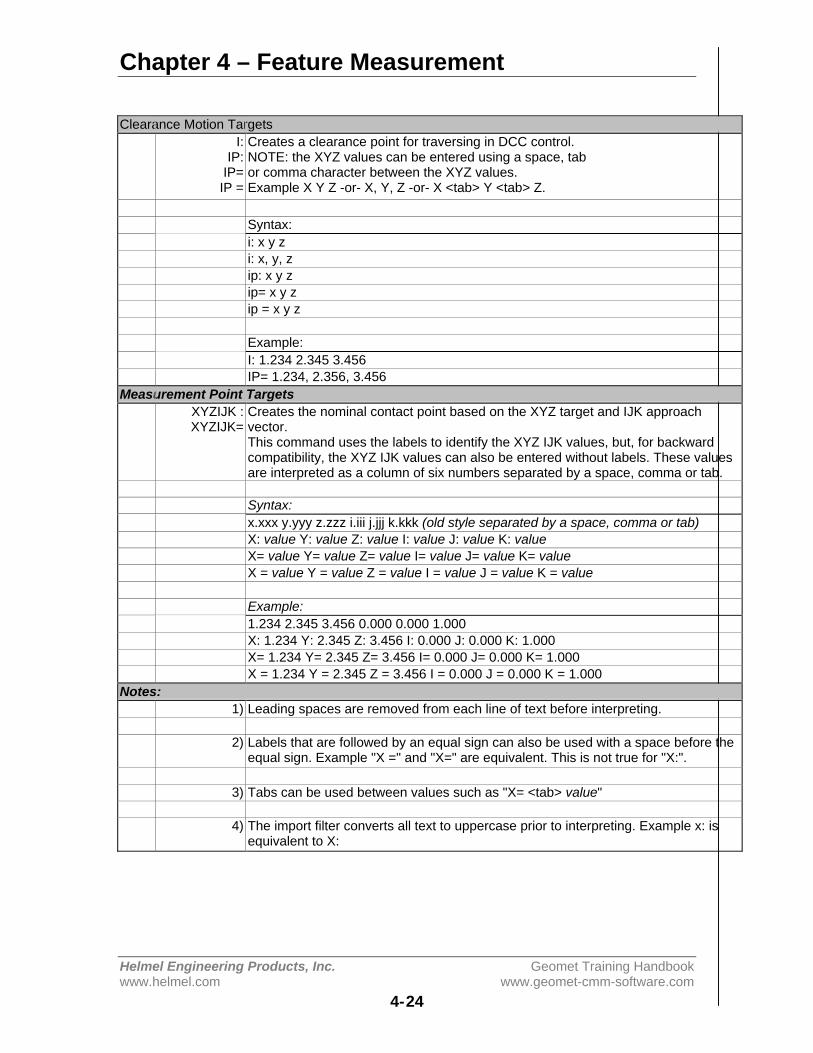
Chapter 4 – Feature Measurement
Helmel Engineering Products, Inc. Geomet Training Handbookwww.helmel.com www.geomet-cmm-software.com
4-24
Clearance Motion TargetsI:
IP:IP=IP =
Creates a clearance point for traversing in DCC control.NOTE: the XYZ values can be entered using a space, tabor comma character between the XYZ values.Example X Y Z -or- X, Y, Z -or- X <tab> Y <tab> Z.
Syntax:i: x y zi: x, y, zip: x y zip= x y zip = x y z
Example:I: 1.234 2.345 3.456IP= 1.234, 2.356, 3.456
Measurement Point TargetsXYZIJK :XYZIJK=
Creates the nominal contact point based on the XYZ target and IJK approachvector.This command uses the labels to identify the XYZ IJK values, but, for backwardcompatibility, the XYZ IJK values can also be entered without labels. These valuesare interpreted as a column of six numbers separated by a space, comma or tab.
Syntax:x.xxx y.yyy z.zzz i.iii j.jjj k.kkk (old style separated by a space, comma or tab)X: value Y: value Z: value I: value J: value K: valueX= value Y= value Z= value I= value J= value K= valueX = value Y = value Z = value I = value J = value K = value
Example:1.234 2.345 3.456 0.000 0.000 1.000X: 1.234 Y: 2.345 Z: 3.456 I: 0.000 J: 0.000 K: 1.000X= 1.234 Y= 2.345 Z= 3.456 I= 0.000 J= 0.000 K= 1.000X = 1.234 Y = 2.345 Z = 3.456 I = 0.000 J = 0.000 K = 1.000
Notes:1) Leading spaces are removed from each line of text before interpreting.
2) Labels that are followed by an equal sign can also be used with a space before theequal sign. Example "X =" and "X=" are equivalent. This is not true for "X:".
3) Tabs can be used between values such as "X= <tab> value"
4) The import filter converts all text to uppercase prior to interpreting. Example x: isequivalent to X:
Chapter 4 – Feature Measurement
Helmel Engineering Products, Inc. Geomet Training Handbookwww.helmel.com www.geomet-cmm-software.com
4-25
Vector Point ASCII Table
The table is made up of 2 main sections. These are the Header and BlockDescriptions. The Header is data that can set a global setting for use by all Blocks.Block Descriptions contain the actual targeting data and supporting tolerance,motion, probe and text data.
Keywords used in the table are not upper or lowercase sensitive and can beentered in either. Geomet always interprets keywords in uppercase and performsthe operation automatically.
Vector Point ASCII Table Header
The header has limited keywords that control the global settings for theirrespective features.
Keyword DescriptionU: Unit of MeasurementS: Stand Off DistanceO: Over Travel DistanceH: Upper Tolerance ValueL: Lower Tolerance ValueE: Probe Deviation
An example of a header would be:
U: InchS: 0.50O: 0.50H: 0.001L: -0.001E: 0.0002
Should any of the header items be missing from the ASCII import file, Geometwill prompt for a starting value when the file is opened. This does not apply toUnit of Measure. The keywords shown above can also be used in BlockDescriptions.
Chapter 4 – Feature Measurement
Helmel Engineering Products, Inc. Geomet Training Handbookwww.helmel.com www.geomet-cmm-software.com
4-26
Vector Point ASCII Table Block Descriptions
An imported data file can contain many blocks of data defined by a 'start' and'stop' keyword. This allows organization of common Vector Points. For example;a block of vector points may contain all necessary points required for the topsurface of the part being inspected. A second block can be used to group all vectorpoints for the front surface.
The process of building blocks of data can be helpful for use on DCC styleCMMs. By grouping all common vector points, an auto run through the list can bedone without concern of positioning the probe around corners or other obstacles.In example #3, we show how mixing vector points with interim points (IP) tocreate a complete motion path to capture data points on more than a side of theGeoWidget. Another use of blocks can be to group all common tolerance bandstogether.
A block is always started by the keyword "start" followed by vector pointinstructions and always ends with a "stop". An example might look like:
STARTKeywords / Instructions......Keywords / Instructions......Keywords / Instructions......
STOP
Vector Point ASCII Table Creating in Excel
Creating the Vector Point ASCII data file in Excel is one method used where thepower of a spreadsheets internal math functions can assist in developing thetargeting tables.
For example, should you want to create a table of vector points that covers a largearea using a uniform grid of rows and columns, Excel would be used with the fillrange tools or copying formulas. In sample #4, you will see the spreadsheet usesformulas to step the vector points in a column by changing the Y target value,0.25" between each point.
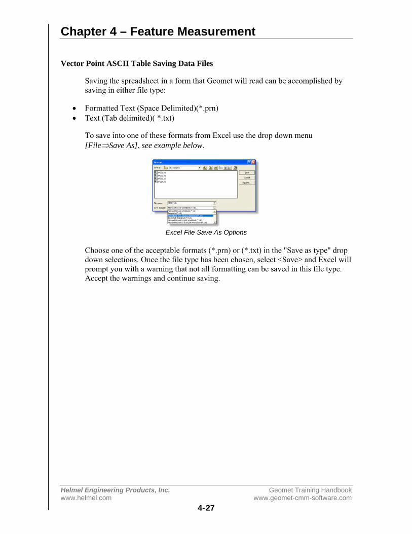
Chapter 4 – Feature Measurement
Helmel Engineering Products, Inc. Geomet Training Handbookwww.helmel.com www.geomet-cmm-software.com
4-27
Vector Point ASCII Table Saving Data Files
Saving the spreadsheet in a form that Geomet will read can be accomplished bysaving in either file type:
• Formatted Text (Space Delimited)(*.prn)• Text (Tab delimited)( *.txt)
To save into one of these formats from Excel use the drop down menu[File⇒Save As], see example below.
Excel File Save As Options
Choose one of the acceptable formats (*.prn) or (*.txt) in the "Save as type" dropdown selections. Once the file type has been chosen, select <Save> and Excel willprompt you with a warning that not all formatting can be saved in this file type.Accept the warnings and continue saving.

Chapter 4 – Feature Measurement
Helmel Engineering Products, Inc. Geomet Training Handbookwww.helmel.com www.geomet-cmm-software.com
4-28
Vector Point ASCII Table Keyword Reference Table
Each keyword used in the Vector Point data file utilizes a fixed syntax for properapplication. In some cases there are more than one syntax for a keyword. Thetables below help to demonstrate the proper application.
keyword START
Identifies the beginning of a block. Must have a STOP keyword associated at theend of the block. There are no parameters following the keyword.
usage START
keyword STOP
Identifies the end of a block. Must have a START keyword associated at thebeginning of the block. There are no parameters following the keyword.
usage STOP
keyword N:
Used within the START and STOP keywords to attach a label to the block. Thereshould be only 1 N: associated with each block. The naming of a block is optionaland should there be no name included, the label for the block will be a sequentialnumber starting with 1.
usage N: Top Surface of GeoWidget
keyword U:
Unit of Measurement. Prepares the data to be imported and reported in metric orinch modes. This does not place a record in the current inspection report.
usage U:metric, U:mm, U:inch
keyword PROBE:
Activates a requested stylus. This feature will place a stylus record in theinspection report.
usage PROBE: 2

Chapter 4 – Feature Measurement
Helmel Engineering Products, Inc. Geomet Training Handbookwww.helmel.com www.geomet-cmm-software.com
4-29
keyword M: -or- TEXT:
Places a standard Geomet text statement in the inspection report.
usage M: Top surface of the GeoWidgetusage TEXT: Top surface of the GeoWidget
keyword H:
Establishes the upper limit for the Vector Point profile band. The value attachedto this keyword is sign sensitive.
usage H: 0.001
keyword L:
Establishes the lower limit for the Vector Point profile band. The value attachedto this keyword is sign sensitive. Should you require a profile band of +0.001 / -0.001 you must enter -0.001 as shown below.
usage L: -0.001
keyword E:
Establishes the Probe Deviation or probing error limit. This value must be >0.000.
usage E: 0.0002
keyword T:
Attaches Print Exception Tags on the reported Vector Point values based on theparameters shown after the keyword. The available parameters are X, Y and Zused alone or in any combination. for example, using the X alone will tag only theX reported value. Using XZ or ZX will attach a tag to X and Z values.
usage T:XYZ
Chapter 4 – Feature Measurement
Helmel Engineering Products, Inc. Geomet Training Handbookwww.helmel.com www.geomet-cmm-software.com
4-30
keyword I:, IP:, IP=, IP =
Creates an Interim Point (IP) used during DCC operations to traverse betweenXYZ locations. These values are entered in local Part Coordinate System values.There are 4 variants to entering Interim points, see usage.
An interim point has 3 values; X, Y and Z. The import filter will accept a spacecomma or tab between the values.
usage X Y ZI: 1.234 2.345 3.456I: 1.234, 2.345, 3.456
IP: 1.234 2.345 3.456IP= 1.234, 2.345, 3.456IP = 1.234 2.345 3.456
keyword X: Y: Z: I: J: K:, X= Y= Z= I= J= K=
Creates the Vector Point target. This is the expected point of contact on a nominalsurface. This value also is inserted in the tolerance nominal of the vector pointbeing created. These values are entered in local Part Coordinate System values.There are 4 variants to entering Interim points, see usage. NOTE: to ensurecompatibility with previous versions of Geomet, a target point can also be definedwithout any prefix values. In these instances, the XYZ and IJK values are enteredin s columns and extracted into; column 1 = X, column 2 = y, etc.
An interim point has 3 values; X, Y and Z. The import filter will accept a spacecomma or tab between the values.
usage1.10 2.20 3.30 0.00 0.00 1.001.10, 2.20, 3.30, 0.00, 0.00, 1.00
X: 1.10 Y: 2.20 Z: 3.30 I: 0.00 J: 0.00 K: 1.00X= 1.10 Y= 2.20 Z= 3.30 I= 0.00 J= 0.00 K= 1.00X = 1.10 Y = 2.20 Z = 3.30 I = 0.00 J = 0.00 K = 1.00
keyword PROBESP:
Updates the current probe speed for use on DCC style CMMs.Valid limits: 0.010" - 1.000" (0.254mm - 25.4mm)
usage PROBESP: 0.25

Chapter 4 – Feature Measurement
Helmel Engineering Products, Inc. Geomet Training Handbookwww.helmel.com www.geomet-cmm-software.com
4-31
keyword TRAVSP:
Updates the current traverse speed for use or DCC style CMMs.Valid limits: 0.01" - 20.0" (0.254mm - 508.0mm)
NOTE: Some CMMs have internal limits on maximum traverse speeds maybeless than the valid limit shown above.
usage TRAVSP: 10.0
keyword S:
Establishes the standoff distance for use with DCC style CMMs. This is thedistance along the vector point surface normal (IJK) above the expected targetpoint where the probe will position itself prior to commencing the measurementmove to capture the XYZ target. This point along the vector normal is referred asa Stand Off point and is calculated at the time of executing the vector point datafile.
The smaller the stand off distance, the greater the chance of missing your targetpoints. This is caused by the instability of the vector motion approach from thestand off point to the target point. The CMM will attempt to follow the IJK vectorto the target point but is influenced by the mass of the CMM, the speed prior tostarting the probe move, the speed of the probe move and the stability of themotor tuning. It is suggested, that a minimum standoff distance of 0.50" and aslower probe speed of 0.20" be used in all cases where possible.
One analogy to explain probe motion is to understand the physics of driving a car.Most drivers when approaching a corner will slow down to make the turn smooth.However, should you turn while driving too fast, your car will overshoot theexpected turning radius. The driver will then have to compensate to get back tothe center of the turning radius, or lane. The car will then overshoot the expectedlane due to the mass of the car pushing beyond the center point. The car will thensway back and forth while stabilizing toward the center of the driving lane.
CMMs are no different. A heavy CMM will require slower speeds during tightturns or to follow a projected path accurately.
usage S: 0.50

Chapter 4 – Feature Measurement
Helmel Engineering Products, Inc. Geomet Training Handbookwww.helmel.com www.geomet-cmm-software.com
4-32
keyword O:
Defines the Over Travel distance the probe will travel past the expected XYZmeasurement contact point. Should the probe movement reach this distance, allmotion stops as a safety precaution.
The over travel distance should be sufficient to allow safe passage of the probewithout allowing contact with the body or head of the probe.
usage O: 0.75
Vector Point ASCII Table Execution
When the vector point ASCII data file has been opened, the execution of that datawill depend on whether you have a manual or DCC style CMM. To execute, startby selecting the block from the data file in the drop down tool labeled "SelectBlock->", see example below.
Select Vector Point Block
To execute the vector point information contained in the block on a manualCMM, select the <Ok> button. The behavior of the targeting will be the same asdefined in Manual Application of Method 4. However, the vector point importtool will supply the XYZ and IJK values with every entry in the data block.
Executing the vector point data file on a DCC system can be done in 2 methods.Depending on the information in the vector point data file, you can choose toexecute one point at a time, or run the entire block.
Executing one point at a time allows the building of the motion map by manuallyteaching the probe path and entering IPs by pressing the IP button on the joystick.Geomet will provide a targeting box to the standoff point before the expectedXYZ contact point, as described in DCC Application of Method 4. To performthis method, press the <Ok> button. When each point has been completed, thevector point import tool will advance to the next point in the data file and promptyou to proceed with the next step.
Should you have data blocks that include all information necessary to allow safetransition of the probe between vector points, select the <AutoRun> button fromthe dialog. This will execute all vector points in the data block. In example #3,you will find a data block that contains all the motion required to move the probesafely around the GeoWidget and capture several vector points.
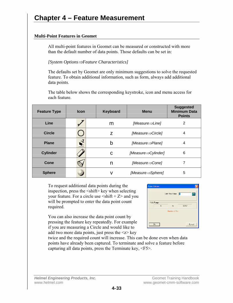
Chapter 4 – Feature Measurement
Helmel Engineering Products, Inc. Geomet Training Handbookwww.helmel.com www.geomet-cmm-software.com
4-33
Multi-Point Features in Geomet
All multi-point features in Geomet can be measured or constructed with morethan the default number of data points. Those defaults can be set in:
[System Options⇒Feature Characteristics]
The defaults set by Geomet are only minimum suggestions to solve the requestedfeature. To obtain additional information, such as form, always add additionaldata points.
The table below shows the corresponding keystroke, icon and menu access foreach feature.
Feature Type Icon Keyboard MenuSuggested
Minimum DataPoints
Line m [Measure⇒Line] 2
Circle z [Measure⇒Circle] 4
Plane b [Measure⇒Plane] 4
Cylinder c [Measure⇒Cylinder] 6
Cone n [Measure⇒Cone] 7
Sphere v [Measure⇒Sphere] 5
To request additional data points during theinspection, press the <shift> key when selectingyour feature. For a circle use <shift + Z> and youwill be prompted to enter the data point countrequired.
You can also increase the data point count bypressing the feature key repeatedly. For exampleif you are measuring a Circle and would like toadd two more data points, just press the <z> keytwice and the required count will increase. This can be done even when datapoints have already been captured. To terminate and solve a feature beforecapturing all data points, press the Terminate key, <F5>.
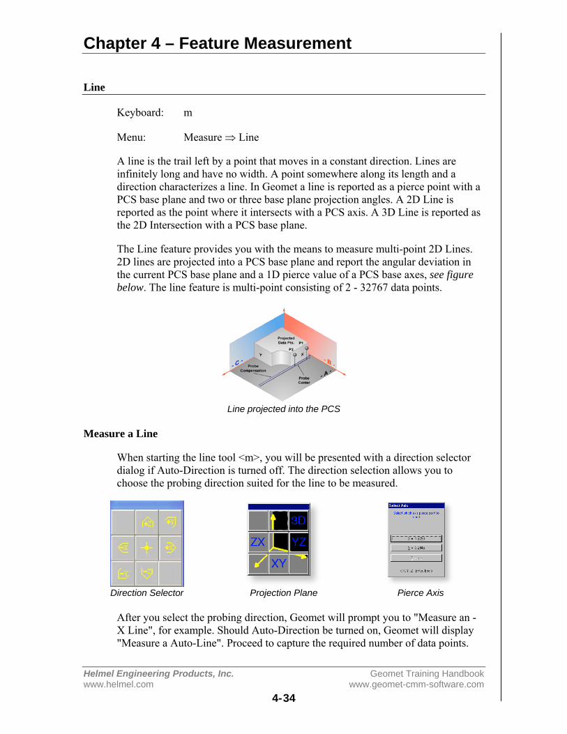
Chapter 4 – Feature Measurement
Helmel Engineering Products, Inc. Geomet Training Handbookwww.helmel.com www.geomet-cmm-software.com
4-34
Line
Keyboard: m
Menu: Measure ⇒ Line
A line is the trail left by a point that moves in a constant direction. Lines areinfinitely long and have no width. A point somewhere along its length and adirection characterizes a line. In Geomet a line is reported as a pierce point with aPCS base plane and two or three base plane projection angles. A 2D Line isreported as the point where it intersects with a PCS axis. A 3D Line is reported asthe 2D Intersection with a PCS base plane.
The Line feature provides you with the means to measure multi-point 2D Lines.2D lines are projected into a PCS base plane and report the angular deviation inthe current PCS base plane and a 1D pierce value of a PCS base axes, see figurebelow. The line feature is multi-point consisting of 2 - 32767 data points.
Line projected into the PCS
Measure a Line
When starting the line tool <m>, you will be presented with a direction selectordialog if Auto-Direction is turned off. The direction selection allows you tochoose the probing direction suited for the line to be measured.
Direction Selector Projection Plane Pierce Axis
After you select the probing direction, Geomet will prompt you to "Measure an -X Line", for example. Should Auto-Direction be turned on, Geomet will display"Measure a Auto-Line". Proceed to capture the required number of data points.

Chapter 4 – Feature Measurement
Helmel Engineering Products, Inc. Geomet Training Handbookwww.helmel.com www.geomet-cmm-software.com
4-35
The determination of the PCS base plane is supplied by the operator after thecapturing of the data points. Depending on the angle of the line, Geomet willprompt for the selection of a PCS axis to report. Geomet uses an angle of ± 10°between the line normal to a PCS axis to determine if the operator should beprompted to select the pierce axis.
For example, if a line being measured crosses the PCS X axis at 1.000" and has areported angle of 85°, the operator will not be prompted to select a PCS axis.Should the same line have a reported angle of 75°, then Geomet would prompt theoperator to select the pierce axis showing the solutions of both values as shown inPierce Axis figure on the previous page.
After completing the first measured line, Geomet auto-cycles preparing tomeasure another line. Note: after the first measure line is completed, Geomet willnot prompt you for a projection plane. It is assumed that you will continuemeasuring lines in the original selected plane. Should you require a newprojection plane, press <Esc> and select the line tool again.
The direction of the line is determined by the direction of the data points, from thefirst data point to the second. In our example, the order the data points werecaptured created a reported angle of -90° whereas should the order have beenreversed, the reported angle would be +90°. NOTE: see Switching the ReportedAngle Directions below. This is important when applying a tolerance value to theangular component.
During the capturing of the data points, should you want to change the requestednumber of data points you can press the line key repeatedly and the count willincrease by one with every depress without losing data points already captured.
If you have already captured sufficient data points to satisfy the line press <f5>,Terminate, to solve the line without having to capture the remaining prompteddata points.
Tolerancing of Lines is available in Cartesian / Linear format.
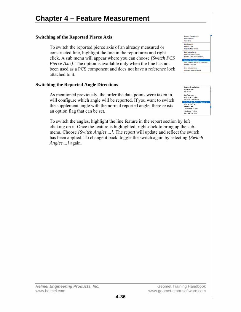
Chapter 4 – Feature Measurement
Helmel Engineering Products, Inc. Geomet Training Handbookwww.helmel.com www.geomet-cmm-software.com
4-36
Switching of the Reported Pierce Axis
To switch the reported pierce axis of an already measured orconstructed line, highlight the line in the report area and right-click. A sub menu will appear where you can choose [Switch PCSPierce Axis]. The option is available only when the line has notbeen used as a PCS component and does not have a reference lockattached to it.
Switching the Reported Angle Directions
As mentioned previously, the order the data points were taken inwill configure which angle will be reported. If you want to switchthe supplement angle with the normal reported angle, there existsan option flag that can be set.
To switch the angles, highlight the line feature in the report section by leftclicking on it. Once the feature is highlighted, right-click to bring up the sub-menu. Choose [Switch Angles....]. The report will update and reflect the switchhas been applied. To change it back, toggle the switch again by selecting [SwitchAngles....] again.
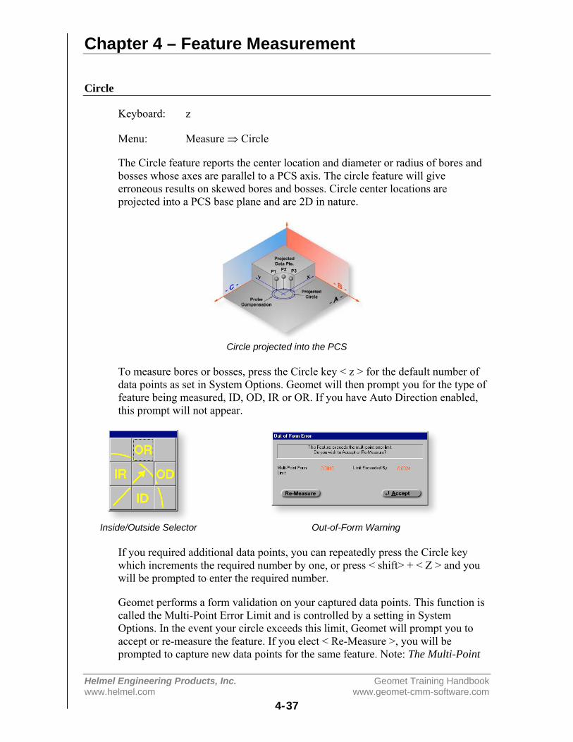
Chapter 4 – Feature Measurement
Helmel Engineering Products, Inc. Geomet Training Handbookwww.helmel.com www.geomet-cmm-software.com
4-37
Circle
Keyboard: z
Menu: Measure ⇒ Circle
The Circle feature reports the center location and diameter or radius of bores andbosses whose axes are parallel to a PCS axis. The circle feature will giveerroneous results on skewed bores and bosses. Circle center locations areprojected into a PCS base plane and are 2D in nature.
Circle projected into the PCS
To measure bores or bosses, press the Circle key < z > for the default number ofdata points as set in System Options. Geomet will then prompt you for the type offeature being measured, ID, OD, IR or OR. If you have Auto Direction enabled,this prompt will not appear.
Inside/Outside Selector Out-of-Form Warning
If you required additional data points, you can repeatedly press the Circle keywhich increments the required number by one, or press < shift> + < Z > and youwill be prompted to enter the required number.
Geomet performs a form validation on your captured data points. This function iscalled the Multi-Point Error Limit and is controlled by a setting in SystemOptions. In the event your circle exceeds this limit, Geomet will prompt you toaccept or re-measure the feature. If you elect < Re-Measure >, you will beprompted to capture new data points for the same feature. Note: The Multi-Point
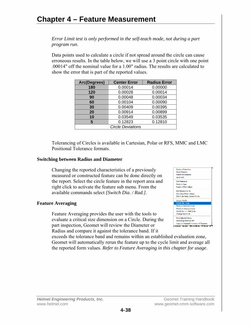
Chapter 4 – Feature Measurement
Helmel Engineering Products, Inc. Geomet Training Handbookwww.helmel.com www.geomet-cmm-software.com
4-38
Error Limit test is only performed in the self-teach mode, not during a partprogram run.
Data points used to calculate a circle if not spread around the circle can causeerroneous results. In the table below, we will use a 3 point circle with one point.00014" off the nominal value for a 1.00" radius. The results are calculated toshow the error that is part of the reported values.
Arc(Degrees) Center Error Radius Error180 0.00014 0.00000120 0.00028 0.0001490 0.00048 0.0003460 0.00104 0.0009030 0.00409 0.0039520 0.00914 0.0089910 0.03549 0.035355 0.12823 0.12810
Circle Deviations
Tolerancing of Circles is available in Cartesian, Polar or RFS, MMC and LMCPositional Tolerance formats.
Switching between Radius and Diameter
Changing the reported characteristics of a previouslymeasured or constructed feature can be done directly onthe report. Select the circle feature in the report area andright click to activate the feature sub menu. From theavailable commands select [Switch Dia. / Rad.].
Feature Averaging
Feature Averaging provides the user with the tools toevaluate a critical size dimension on a Circle. During thepart inspection, Geomet will review the Diameter orRadius and compare it against the tolerance band. If itexceeds the tolerance band and remains within an established evaluation zone,Geomet will automatically rerun the feature up to the cycle limit and average allthe reported form values. Refer to Feature Averaging in this chapter for usage.

Chapter 4 – Feature Measurement
Helmel Engineering Products, Inc. Geomet Training Handbookwww.helmel.com www.geomet-cmm-software.com
4-39
Plane
Keyboard: b
Menu: Measure ⇒ Plane
Planes have locations, attitudes and directions. The location of a plane is definedas the point at which it is pierced by a PCS axis. The attitude of a plane is definedby the projection angle AX/Y, AY/Z and AZ/X of the plane normal in each of thethree PCS base planes, with range values from 0° to ± 180°.
Plane represented in the current PCS
The Plane feature may be used to measure non-skewed planes. The printed piercepoint of a measured plane is determined by the PCS axis that is most parallel tothe normal of the measured plane. Planes which are essentially parallel to PCSbase planes have only two attitude angles which are meaningful, the third isprinted in lower case, as for example "ax/y" to indicate its reduced significance.
AX/Y Projection AY/Z Projection AZ/X Projection
The vector normal defines the direction of a plane. The first figure above shows aplane with its projection into each PCS base plane. The normal, when projectedinto each PCS base plane provides the attitude in angles, see example above.

Chapter 4 – Feature Measurement
Helmel Engineering Products, Inc. Geomet Training Handbookwww.helmel.com www.geomet-cmm-software.com
4-40
Probe Direction Selector Out-of-Form Warning
To measure Planes press the Plane key <b> for the default number of hits asestablished in System Options, or < shift> + < B > for a multi-point plane. If yourequired additional data points even during point capture, you can repeatedlypress the Plane key which increments the required number by one. If auto-direction is not enabled, you will be prompted to enter the probing direction.Upon completion of gathering your required number of data points, Geomet willtest the form error of the newly calculated plane. If the form error exceeds thedefault setting, you will be prompted to < Accept > or < Re-Measure > the plane.
Pierce Point Reporting
It is important that your PCS be established close to the desired location where thedistance should be taken. As shown in figure below, should the PCS be outsidethe effective location the distance is expected, the reported result will notrepresent the actual distance.
Referring to figure below, we have two established Part Coordinate Systems. PCS1, established on the base of the 2.000" gage block. PCS 2 is located 4.000"inches in the X direction from the right side of the gage block.
Two planes were measured, one representing the lower base and one on top of thegage block, The lower base plane was used to establish the XY PCS Base Planefor both PCS 1 and 2. The top plane had an AZ/X of 89.9943° and the AY/Z was

Chapter 4 – Feature Measurement
Helmel Engineering Products, Inc. Geomet Training Handbookwww.helmel.com www.geomet-cmm-software.com
4-41
90.0000°. The intersection of the pierce point with the PCS1 Z-Axis, d1, isreported at 1.9999". The reported pierce point on the Z-axis of PCS2, d2 is1.9995". By not having PCS localized to the actual measured surfaces weintroduced 0.0004", d3, error!
Upper / Lower Boundary Planes
The definition of the Boundary Plane is a plane that passes through the minimumor maximum extreme data point of a measured or constructed plane and parallelto that reported plane. This plane can be used in all cases which a measured orconstructed plane is be used such as PCS components, constructions andtolerance.
Boundary Plane Menu Boundary Plane Visual Example
Geomet offers two directions from which you can choose, Upper and Lower. TheUpper Boundary Plane represents the plane constructed at the most positive sideof the reported pierce point. For example a plane reported at Z: +1.345 might havean Upper Boundary Plane reported at +1.349.
To use the feature, measure or construct a plane, select the plane directly on thereport by left-clicking our mouse over the feature to highlight it . Activate thefeature menu by right clicking and a menu similar to the one shown above willpop-up. Choose Upper or Lower Boundary Plane and the feature will recalculateshowing the new reported values.
It is suggested to recall the plane, then apply the Boundary plane change to therecalled plane. This ensures the original plane is available for other constructionor tolerance requirements.
If you do not have the Upper/Lower menu selections in your pop-up, the planeyou have selected is referenced by another operation. You can only change thereported values on planes that have no reference. However you can recall theplane and then apply Upper/Lower Boundary Plane.

Chapter 4 – Feature Measurement
Helmel Engineering Products, Inc. Geomet Training Handbookwww.helmel.com www.geomet-cmm-software.com
4-42
One example in which this feature can be used is to determine the width of a slot,see figure below. Where the effective distance is the closest two points as if agage block were used to identify the width of a slot. Select the plane representingone side of the slot and report it as an upper boundary plane, then select theopposite plane and report it as the lower. Obtain the distance <s> between theplanes and that distance will represent the closest points in the slot.
Boundary Plane Slot Example
Tolerancing of Planes is available in Cartesian / Linear format.
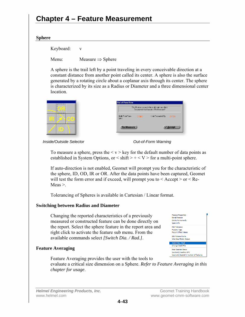
Chapter 4 – Feature Measurement
Helmel Engineering Products, Inc. Geomet Training Handbookwww.helmel.com www.geomet-cmm-software.com
4-43
Sphere
Keyboard: v
Menu: Measure ⇒ Sphere
A sphere is the trail left by a point traveling in every conceivable direction at aconstant distance from another point called its center. A sphere is also the surfacegenerated by a rotating circle about a coplanar axis through its center. The sphereis characterized by its size as a Radius or Diameter and a three dimensional centerlocation.
Inside/Outside Selector Out-of-Form Warning
To measure a sphere, press the < v > key for the default number of data points asestablished in System Options, or < shift > + < V > for a multi-point sphere.
If auto-direction is not enabled, Geomet will prompt you for the characteristic ofthe sphere, ID, OD, IR or OR. After the data points have been captured, Geometwill test the form error and if exceed, will prompt you to < Accept > or < Re-Meas >.
Tolerancing of Spheres is available in Cartesian / Linear format.
Switching between Radius and Diameter
Changing the reported characteristics of a previouslymeasured or constructed feature can be done directly onthe report. Select the sphere feature in the report area andright click to activate the feature sub menu. From theavailable commands select [Switch Dia. / Rad.].
Feature Averaging
Feature Averaging provides the user with the tools toevaluate a critical size dimension on a Sphere. Refer to Feature Averaging in thischapter for usage.

Chapter 4 – Feature Measurement
Helmel Engineering Products, Inc. Geomet Training Handbookwww.helmel.com www.geomet-cmm-software.com
4-44
Cylinder
Keyboard: c, Shift + C
Menu: Measure ⇒ Cylinder
A cylinder is the trail left by a line, which revolves around and at a constantdistance away from a parallel line called its axis. A cylinder is characterized by apoint and direction of its axis and by its diameter or radius.
Cylinder Projection in the current PCS
The cylinder feature determines the size, PCS pierce point and attitude of the axisof bores and shafts. The attitude of a cylinder axis is expressed like the attitude ofthe normal of a plane, using the characteristic identifiers AX/Y, AY/Z and AZ/X.These angles can vary between 0° and ± 180°. The axis of a cylinder has adirection as well as an attitude: its direction is from a group of points measurednear its bottom toward a group of points measured near its top.
The reporting of the position in the PCS is the point where the axis of the cylinderintersects a PCS base plane, called its pierce point. Geomet determines whichPCS base plane to report by determining which PCS base plane the axis of thecylinder is most normal to.
Inside/Outside Selector Out-of-Form Warning
To measure bores or bosses press the Cylinder key <c> for the default number ofdata points as established in System Options, or <shift> + < C > for a multi-pointcylinder.
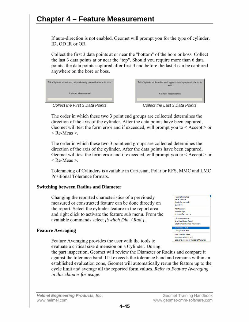
Chapter 4 – Feature Measurement
Helmel Engineering Products, Inc. Geomet Training Handbookwww.helmel.com www.geomet-cmm-software.com
4-45
If auto-direction is not enabled, Geomet will prompt you for the type of cylinder,ID, OD IR or OR.
Collect the first 3 data points at or near the "bottom" of the bore or boss. Collectthe last 3 data points at or near the "top". Should you require more than 6 datapoints, the data points captured after first 3 and before the last 3 can be capturedanywhere on the bore or boss.
Collect the First 3 Data Points Collect the Last 3 Data Points
The order in which these two 3 point end groups are collected determines thedirection of the axis of the cylinder. After the data points have been captured,Geomet will test the form error and if exceeded, will prompt you to < Accept > or< Re-Meas >.
The order in which these two 3 point end groups are collected determines thedirection of the axis of the cylinder. After the data points have been captured,Geomet will test the form error and if exceeded, will prompt you to < Accept > or< Re-Meas >.
Tolerancing of Cylinders is available in Cartesian, Polar or RFS, MMC and LMCPositional Tolerance formats.
Switching between Radius and Diameter
Changing the reported characteristics of a previouslymeasured or constructed feature can be done directly onthe report. Select the cylinder feature in the report areaand right click to activate the feature sub menu. From theavailable commands select [Switch Dia. / Rad.].
Feature Averaging
Feature Averaging provides the user with the tools toevaluate a critical size dimension on a Cylinder. Duringthe part inspection, Geomet will review the Diameter or Radius and compare itagainst the tolerance band. If it exceeds the tolerance band and remains within anestablished evaluation zone, Geomet will automatically rerun the feature up to thecycle limit and average all the reported form values. Refer to Feature Averagingin this chapter for usage.
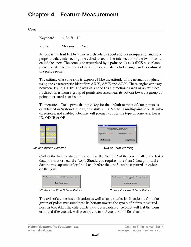
Chapter 4 – Feature Measurement
Helmel Engineering Products, Inc. Geomet Training Handbookwww.helmel.com www.geomet-cmm-software.com
4-46
Cone
Keyboard: n, Shift + N
Menu: Measure ⇒ Cone
A cone is the trail left by a line which rotates about another non-parallel and non-perpendicular, intersecting line called its axis. The intersection of the two lines iscalled the apex. The cone is characterized by a point on its axis (PCS base planepierce point), the direction of its axis, its apex, its included angle and its radius atthe pierce point.
The attitude of a cone axis is expressed like the attitude of the normal of a plane,using the characteristic identifiers AX/Y, AY/Z and AZ/X. These angles can varybetween 0° and ± 180°. The axis of a cone has a direction as well as an attitude:its direction is from a group of points measured near its bottom toward a group ofpoints measured near its top.
To measure a Cone, press the < n > key for the default number of data points asestablished in System Options, or < shift > + < N > for a multi-point cone. If auto-direction is not enabled, Geomet will prompt you for the type of cone as either aID, OD IR or OR.
Inside/Outside Selector Out-of-Form Warning
Collect the first 3 data points at or near the "bottom" of the cone. Collect the last 3data points at or near the "top". Should you require more than 7 data points, thedata points captured after first 3 and before the last 3 can be captured anywhereon the cone.
Collect the First 3 Data Points Collect the Last 3 Data Points
The axis of a cone has a direction as well as an attitude: its direction is from thegroup of points measured near its bottom toward the group of points measurednear its top. After the data points have been captured, Geomet will test the formerror and if exceeded, will prompt you to < Accept > or < Re-Meas >.
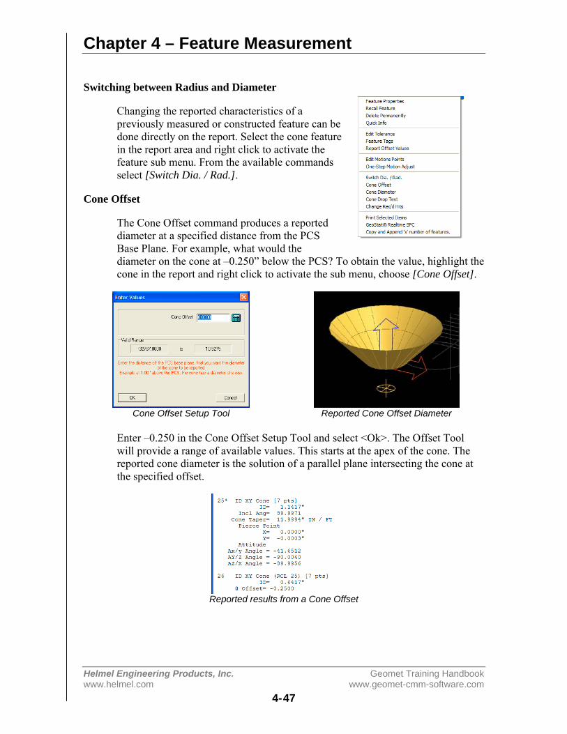
Chapter 4 – Feature Measurement
Helmel Engineering Products, Inc. Geomet Training Handbookwww.helmel.com www.geomet-cmm-software.com
4-47
Switching between Radius and Diameter
Changing the reported characteristics of apreviously measured or constructed feature can bedone directly on the report. Select the cone featurein the report area and right click to activate thefeature sub menu. From the available commandsselect [Switch Dia. / Rad.].
Cone Offset
The Cone Offset command produces a reporteddiameter at a specified distance from the PCSBase Plane. For example, what would thediameter on the cone at –0.250” below the PCS? To obtain the value, highlight thecone in the report and right click to activate the sub menu, choose [Cone Offset].
Cone Offset Setup Tool Reported Cone Offset Diameter
Enter –0.250 in the Cone Offset Setup Tool and select <Ok>. The Offset Toolwill provide a range of available values. This starts at the apex of the cone. Thereported cone diameter is the solution of a parallel plane intersecting the cone atthe specified offset.
Reported results from a Cone Offset
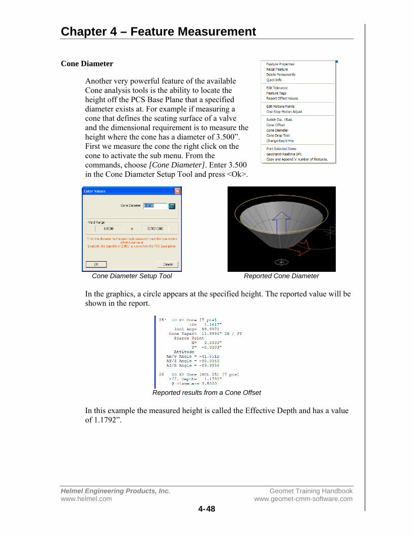
Chapter 4 – Feature Measurement
Helmel Engineering Products, Inc. Geomet Training Handbookwww.helmel.com www.geomet-cmm-software.com
4-48
Cone Diameter
Another very powerful feature of the availableCone analysis tools is the ability to locate theheight off the PCS Base Plane that a specifieddiameter exists at. For example if measuring acone that defines the seating surface of a valveand the dimensional requirement is to measure theheight where the cone has a diameter of 3.500”.First we measure the cone the right click on thecone to activate the sub menu. From thecommands, choose [Cone Diameter]. Enter 3.500in the Cone Diameter Setup Tool and press <Ok>.
Cone Diameter Setup Tool Reported Cone Diameter
In the graphics, a circle appears at the specified height. The reported value will beshown in the report.
Reported results from a Cone Offset
In this example the measured height is called the Effective Depth and has a valueof 1.1792”.

Chapter 4 – Feature Measurement
Helmel Engineering Products, Inc. Geomet Training Handbookwww.helmel.com www.geomet-cmm-software.com
4-49
Cone Drop Ball Test
The Cone Drop Ball Test is used to place a testball in a cone and calculate the diameter andposition where the ball intersects with the cone.
To use this test, right click on the cone in thereport and choose [Cone Drop Test] from the submenu.
Enter the radius of the ball that will be droppedinto the open end of the cone.
Cone Drop Test Setup Tool Showing the Ball Drop
By default the results of the calculation is the XYZ position of the center point ofthe ball and its diameter on the cone where it makes contact. The reportedposition can be switched to the top of the ball by right clicking on the Drop Testrecord and from the sub menu choose [Switch Top <-> Center Reporting].
Cone Drop Test Sub Menu Ball Drop Results

Chapter 4 – Feature Measurement
Helmel Engineering Products, Inc. Geomet Training Handbookwww.helmel.com www.geomet-cmm-software.com
4-50
4-Point Intersect
Keyboard: . (period)
Menu: Measure ⇒ 4 Point Intersect
The 4 Point Intersect routine is used to measure the included angle and 2Dlocation of corners and edges formed by the intersection of two planes both ofwhich must be perpendicular to one and the same PCS base plane. If thiscondition is not met the results will be erroneous.
To measure corners or edges press the 4 Point Intersectkey < . >, choose the first probing direction. Should Auto-Direction be turned on, the selections process for probingdirection will be skipped and Geomet will proceed directlyto the capture data point phase.
Once the direction for the first pair of data points has beenchosen, Geomet will prompt you to "Select Next Probe Direction". Choose theprobing direction for the next pair of data points.
Geomet will prompt to capture the first pair of data points:
4 Point Intersect, Probe -X [1 of 4]
When Auto-Direction is active, the prompt will show:
4 Point Intersect, Probe Auto-Dir [1 of 4]
Capture the data points following the prompted direction. Upon completion of thecapturing 4 data points, Geomet will solve for the 2D location and included anglebetween the two line.
The 4 Point Intersect uses two pointscaptured in the -X direction, Pt1 andPt2. Followed by capturing two +Y datapoints, Pt3 and Pt4, to form the cornerintersect point.
The reported values include a 2Dprojected location and the anglebetween data points Pt1-Pt2 and Pt3-Pt4.
Tolerancing of a 4 Point Intersectfeature is available in Cartesian, Polar or RFS Positional Tolerance formats.
Direction Selector
4-Point Intersect Projection in the current PCS

Chapter 4 – Feature Measurement
Helmel Engineering Products, Inc. Geomet Training Handbookwww.helmel.com www.geomet-cmm-software.com
4-51
Slot / Web
Keyboard: , (comma)
Menu: Measure ⇒ Slot / Web
Slots and Webs consist of hollow or solid spaces between parallel planes. TheSlot / Web routine is only capable of measuring slots and webs whose boundaryplanes are parallel to PCS base planes. The Slot / Web routine determines thewidth of the feature and its center location in either X, Y or Z direction relative tothe current PCS Origin.
To measure a Slot or Web, press the < , > key. Geomet willrespond with the direction selector unless Auto-Direction isactive. Choose the appropriate probe direction. The Slot /Web feature will automatically reverse the probe directionfor the second point at the time of capturing the data points.For example, if you request a -X direction, that will becomethe required probing direction for the first point. The secondpoint will then be captured in the +X direction.
Take one -X data point inside the slot followed by a second +X data pointopposite the first data point. Geomet will calculate the width and centerline of theslot and project the centerline to the PCS x-axis.
NOTE: If Auto-Direction is turned on itis possible to measure 2 data points inthe same direction such as a step. Forexample, establish a PCS by choosingICS⇒PCS followed by a -Z point onthe surface plate and set the Z origin.Place a 1.000" gage block on thesurface plate and measure a Slot / Webwith Auto-Direction turned on. Take adata point on the surface plate followedby a data point on the top surface. Thereported values will show the Width as1.000" and the Z mid-point at 0.500".
It is important to note that slots and webs that are not parallel to the PCS baseplanes will report erroneous data and should not be attempted.
Tolerancing of Slot/Web is available only in Cartesian / Linear format.
Direction Selector
4-Point Intersect Projection in the current PCS

Chapter 4 – Feature Measurement
Helmel Engineering Products, Inc. Geomet Training Handbookwww.helmel.com www.geomet-cmm-software.com
4-52
Oval-Slot
Keyboard: shift + <
Menu: Measure ⇒ Oval Slot
The Oval Slot feature is a routine that connects two circles and reports the center-to-center distance or outside width and slot width values as well as the 2D bisectpoint between centers. An Oval Slot can be treated as any other 2D feature withregard to constructions, tolerance and PCS components.
This feature can be activated either through the measure dropdown menu [Measure⇒Oval Slot] or by pressing the "Shift+ <" keys on the keyboard. When activating, a prompt willshow allowing you to identify the feature characteristic.Select Inside/Outside Radius or Diameter from the selectiontool.
Geomet will then prompt you to measure the first radius of the oval slot. Eachradius will require 3 data points; the prompt will step you through until all sixdata points have been gathered.
Displayed Oval / Slot Oval / Slot Definition
Measure Oval Slot [Rad 1(1/3)]
Graphically you will see a projected outline of the Oval Slot.
Reporting of a Oval Slot
The report generated when measuring an Oval Slot starts with a width value. Thisvalue is the basic width between the two straight and parallel sides. Following thewidth is the Extended Distance or Center-to-Center Distance, depending uponwhich is selected. Extended distance is the outside length of the oval slot. Centerto Center is the distance between radius centers. The position is reported as a 2Dpoint. Standard tolerance tools are applied to all components.
An Oval Slot can be treated as a 2D Point feature when used as a PCS orconstruction component.
Feature Type
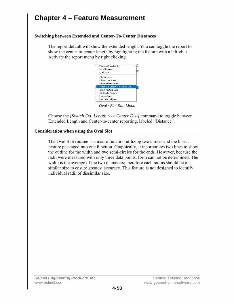
Chapter 4 – Feature Measurement
Helmel Engineering Products, Inc. Geomet Training Handbookwww.helmel.com www.geomet-cmm-software.com
4-53
Switching between Extended and Center-To-Center Distances
The report default will show the extended length. You can toggle the report toshow the center-to-center length by highlighting the feature with a left-click.Activate the report menu by right clicking.
Oval / Slot Sub-Menu
Choose the [Switch Ext. Length <-> Center Dist] command to toggle betweenExtended Length and Center-to-center reporting, labeled “Distance”.
Consideration when using the Oval Slot
The Oval Slot routine is a macro function utilizing two circles and the bisectfeature packaged into one function. Graphically, it incorporates two lines to showthe outline for the width and two semi-circles for the ends. However, because theradii were measured with only three data points, form can not be determined. Thewidth is the average of the two diameters; therefore each radius should be ofsimilar size to ensure greatest accuracy. This feature is not designed to identifyindividual radii of dissimilar size.
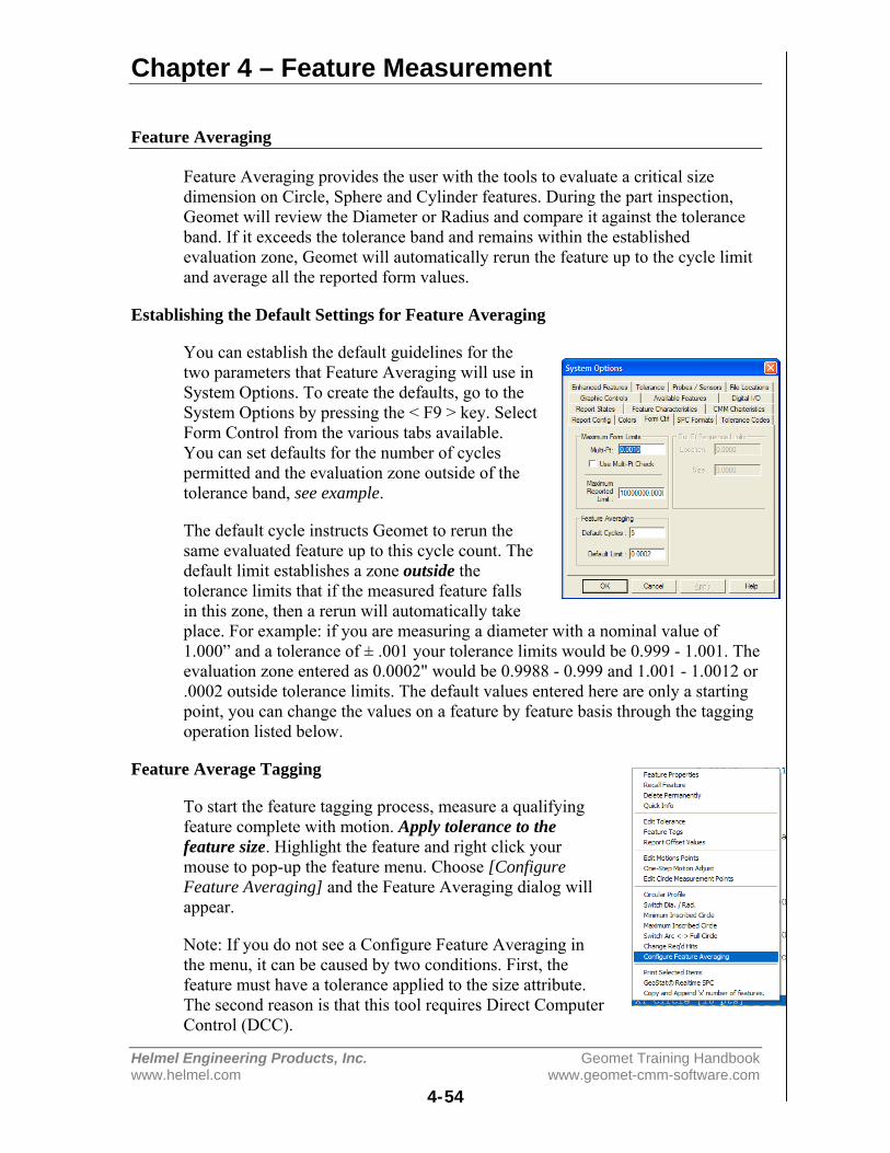
Chapter 4 – Feature Measurement
Helmel Engineering Products, Inc. Geomet Training Handbookwww.helmel.com www.geomet-cmm-software.com
4-54
Feature Averaging
Feature Averaging provides the user with the tools to evaluate a critical sizedimension on Circle, Sphere and Cylinder features. During the part inspection,Geomet will review the Diameter or Radius and compare it against the toleranceband. If it exceeds the tolerance band and remains within the establishedevaluation zone, Geomet will automatically rerun the feature up to the cycle limitand average all the reported form values.
Establishing the Default Settings for Feature Averaging
You can establish the default guidelines for thetwo parameters that Feature Averaging will use inSystem Options. To create the defaults, go to theSystem Options by pressing the < F9 > key. SelectForm Control from the various tabs available.You can set defaults for the number of cyclespermitted and the evaluation zone outside of thetolerance band, see example.
The default cycle instructs Geomet to rerun thesame evaluated feature up to this cycle count. Thedefault limit establishes a zone outside thetolerance limits that if the measured feature fallsin this zone, then a rerun will automatically takeplace. For example: if you are measuring a diameter with a nominal value of1.000” and a tolerance of ± .001 your tolerance limits would be 0.999 - 1.001. Theevaluation zone entered as 0.0002" would be 0.9988 - 0.999 and 1.001 - 1.0012 or.0002 outside tolerance limits. The default values entered here are only a startingpoint, you can change the values on a feature by feature basis through the taggingoperation listed below.
Feature Average Tagging
To start the feature tagging process, measure a qualifyingfeature complete with motion. Apply tolerance to thefeature size. Highlight the feature and right click yourmouse to pop-up the feature menu. Choose [ConfigureFeature Averaging] and the Feature Averaging dialog willappear.
Note: If you do not see a Configure Feature Averaging inthe menu, it can be caused by two conditions. First, thefeature must have a tolerance applied to the size attribute.The second reason is that this tool requires Direct ComputerControl (DCC).
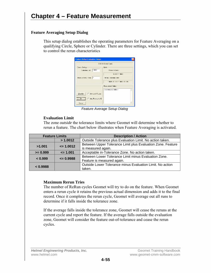
Chapter 4 – Feature Measurement
Helmel Engineering Products, Inc. Geomet Training Handbookwww.helmel.com www.geomet-cmm-software.com
4-55
Feature Averaging Setup Dialog
This setup dialog establishes the operating parameters for Feature Averaging on aqualifying Circle, Sphere or Cylinder. There are three settings, which you can setto control the rerun characteristics
Feature Average Setup Dialog
Evaluation LimitThe zone outside the tolerance limits where Geomet will determine whether torerun a feature. The chart below illustrates when Feature Averaging is activated.
Feature Limits Description / Action> 1.0012 Outside Tolerance plus Evaluation Limit. No action taken.
>1.001 <= 1.0012 Between Upper Tolerance Limit plus Evaluation Zone. Featureis measured again.
>= 0.999 <= 1.001 Acceptable in-Tolerance Zone. No action taken.
< 0.999 <= 0.9988 Between Lower Tolerance Limit minus Evaluation Zone.Feature is measured again.
< 0.9988 Outside Lower Tolerance minus Evaluation Limit. No actiontaken.
Maximum Rerun TriesThe number of ReRun cycles Geomet will try to do on the feature. When Geometenters a rerun cycle it retains the previous actual dimension and adds it to the finalrecord. Once it completes the rerun cycle, Geomet will average out all runs todetermine if it falls inside the tolerance zone.
If the average falls inside the tolerance zone, Geomet will cease the reruns at thecurrent cycle and report the feature. If the average falls outside the evaluationzone, Geomet will consider the feature out-of-tolerance and cease the reruncycles.
Chapter 4 – Feature Measurement
Helmel Engineering Products, Inc. Geomet Training Handbookwww.helmel.com www.geomet-cmm-software.com
4-56
Auto Reverse to SOThis check box is used to control the direction of motion back to the first StandOff (SO). The first SO is the starting point for the first measurement point in themotion map for the feature. On most external features (OD / OR) you shouldreverse direction by placing a check in this box. When Geomet completes thefeature and determines that a rerun is required it will backup though the motionmap through all SOs and IPs to the start of the first measurement point and thenrerun the feature.
If the check is not in place, Geomet will drive from the current location directly tothe first SO. On most internal features, this will not cause a problem.
Measurement ValuesAll currently stored actual measurements will be displayed here for review.
Activate in FeatureWhen this is checked, Feature Averaging is active for this feature.
Feature Averaging during a Part Inspection
During a part inspection, Geomet constantly monitors every feature for theFeature Averaging tag. After gathering the required number of data points for thefeature, Geomet will calculate the diameter or radius and compare it to theevaluation zone. If it is found that the result falls inside the evaluation zone,Geomet will store the actual value in a feature list and display it on the monitor.Then it will return to the first SO under DCC control and rerun the feature.
Once the rerun is completed, Geomet will then average the first and second actualvalues and perform one of the following:
a) Average falls inside tolerance zone: The feature is completed and the results areadded to the report.
b) Average falls inside evaluation zone: Geomet adds the new actual to the list andattempts another rerun. This process continues until either condition a) or c) havebeen met, or until maximum allowed cycles has been reached. If the maximumcycle count has been reached, the feature is reported as out-of-tolerance.
c) Average falls outside evaluation zone: The feature is completed and added tothe report as a feature out-of-tolerance.
The results shown in the report for the Diameter or Radius is the average of allruns. However, the location reported is that of the last run. The averaging featureis designed for use on critical size, not for position.
Chapter 5 – Coordinate Systems
Helmel Engineering Products, Inc. Geomet Training Handbookwww.helmel.com www.geomet-cmm-software.com
5-1
Chapter 5 – Coordinate Systems
Understanding Coordinate Systems................................................... 5-3Machine Coordinate System – MCS............................................ 5-3Part Coordinate System – PCS .................................................... 5-3PCS Base Planes .......................................................................... 5-5PCS versus MCS.......................................................................... 5-5Fixture Coordinate System – FCS ............................................... 5-5Interim Coordinate System – ICS................................................ 5-6Clearance Coordinate Systems – CCS......................................... 5-6Wobble Coordinate System – WCS............................................. 5-6The PCS Setup Guide .................................................................. 5-7
Coordinate System Commands.......................................................... 5-8ICS⇒PCS .................................................................................... 5-8Orient ......................................................................................... 5-10Align .......................................................................................... 5-11Origin ......................................................................................... 5-12Offset Align ............................................................................... 5-13Editing an Offset Align.............................................................. 5-14Pivot Align................................................................................. 5-15Rotate ......................................................................................... 5-16Edit an Existing Rotation Value ................................................ 5-17Translate..................................................................................... 5-18Edit an Existing Translation Value ............................................ 5-19
PCS Program Examples................................................................... 5-20#1, Basic Alignment................................................................... 5-21#2, Plane-Line-Point .................................................................. 5-23#3, Quick PCS............................................................................ 5-25#4, Plane-Circle-Circle .............................................................. 5-27#5, Plane-Cylinder-Circle .......................................................... 5-29#6, Plane-Bisect Points-Circle ................................................... 5-31#7, Cylinder-Circle-Point........................................................... 5-33#8, Plane-Intersect Lines-Bisect Points-Circle .......................... 5-35#9, Offset Alignment ................................................................. 5-38#10, Pivot Alignment ................................................................. 5-39#11, Translate............................................................................. 5-40#12, Rotate ................................................................................. 5-41
Coordinate System Manager............................................................ 5-42Recalling a Part Coordinate System .......................................... 5-42Recalling the Machine Coordinate System................................ 5-42
Chapter 5 – Coordinate Systems
Helmel Engineering Products, Inc. Geomet Training Handbookwww.helmel.com www.geomet-cmm-software.com
5-2
Recalling a Fixture Coordinate System ..................................... 5-42Recalling a Vector Drive System............................................... 5-43
Fixture Coordinate System Manager ............................................... 5-44Import and Convert Pre-Geomet v 6.66 FCS Definitions.......... 5-45Using the FCS Manager............................................................. 5-47Adding a new FCS to the database ............................................ 5-48Selecting a FCS Record ............................................................. 5-49Attach Step................................................................................. 5-49Updating..................................................................................... 5-49Deleting...................................................................................... 5-50Locking ...................................................................................... 5-50Details ........................................................................................ 5-50Delete All ................................................................................... 5-50
Clearance Coordinate Systems ........................................................ 5-51

Chapter 5 – Coordinate Systems
Helmel Engineering Products, Inc. Geomet Training Handbookwww.helmel.com www.geomet-cmm-software.com
5-3
Understanding Coordinate SystemsSupported Geomet Coordinate Systems:
• MCS - Machine Coordinate System• PCS - Part Coordinate System• FCS - Fixture Coordinate System• ICS - Interim Coordinate System• Clearance Coordinate Systems
MCS - Machine Coordinate System
The MCS is the XYZ position on the CMM with respect to the Home Position.The MCS axes are mutually parallel with the movement of the CMM.
Most manual CMMs do not have a home position; therefore the home position isthe location of the CMM at the point of starting the system. Some manual CMMsdo offer a home position that requires the operator to manually move the CMMover reference marks one axis at a time.
On a Direct Computer Control (DCC) system, the start-up procedure requires thatyou "Home" the CMM. This process will drive the CMM one axis at a time, to thedesignated home location and establish a repeatable XYZ zero point.
An MCS is therefore not a valid coordinate system to obtain reliable measuredvalues for your part inspection, unless the part is carefully aligned with themachine axes.
PCS - Part Coordinate System
The PCS is the foundation that establishes the Orientation, Alignment and Originof your part inspection. PCSs are simply the frames of reference in which partfeature locations are defined.
Traditional drawings were made using 2D projections to represent 3D objects.Each 2D view shared a common reference point and common axis of alignmentallowing the building of 3D features. In fact, a 3D dimensional PCS is implied.
Today, it is common to create machined parts using a 3D model created by manypopular CAD tools. These models may contain all necessary information for themachinist to create the part and for the inspector to validate the final production.However, the PCS is still implied using the same procedures as if measured froma 2D drawing.
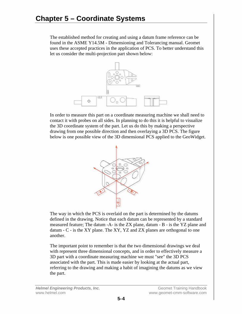
Chapter 5 – Coordinate Systems
Helmel Engineering Products, Inc. Geomet Training Handbookwww.helmel.com www.geomet-cmm-software.com
5-4
The established method for creating and using a datum frame reference can befound in the ASME Y14.5M - Dimensioning and Tolerancing manual. Geometuses these accepted practices in the application of PCS. To better understand thislet us consider the multi-projection part shown below:
In order to measure this part on a coordinate measuring machine we shall need tocontact it with probes on all sides. In planning to do this it is helpful to visualizethe 3D coordinate system of the part. Let us do this by making a perspectivedrawing from one possible direction and then overlaying a 3D PCS. The figurebelow is one possible view of the 3D dimensional PCS applied to the GeoWidget.
The way in which the PCS is overlaid on the part is determined by the datumsdefined in the drawing. Notice that each datum can be represented by a standardmeasured feature; The datum -A- is the ZX plane, datum - B - is the YZ plane anddatum - C - is the XY plane. The XY, YZ and ZX planes are orthogonal to oneanother.
The important point to remember is that the two dimensional drawings we dealwith represent three dimensional concepts, and in order to effectively measure a3D part with a coordinate measuring machine we must "see" the 3D PCSassociated with the part. This is made easier by looking at the actual part,referring to the drawing and making a habit of imagining the datums as we viewthe part.
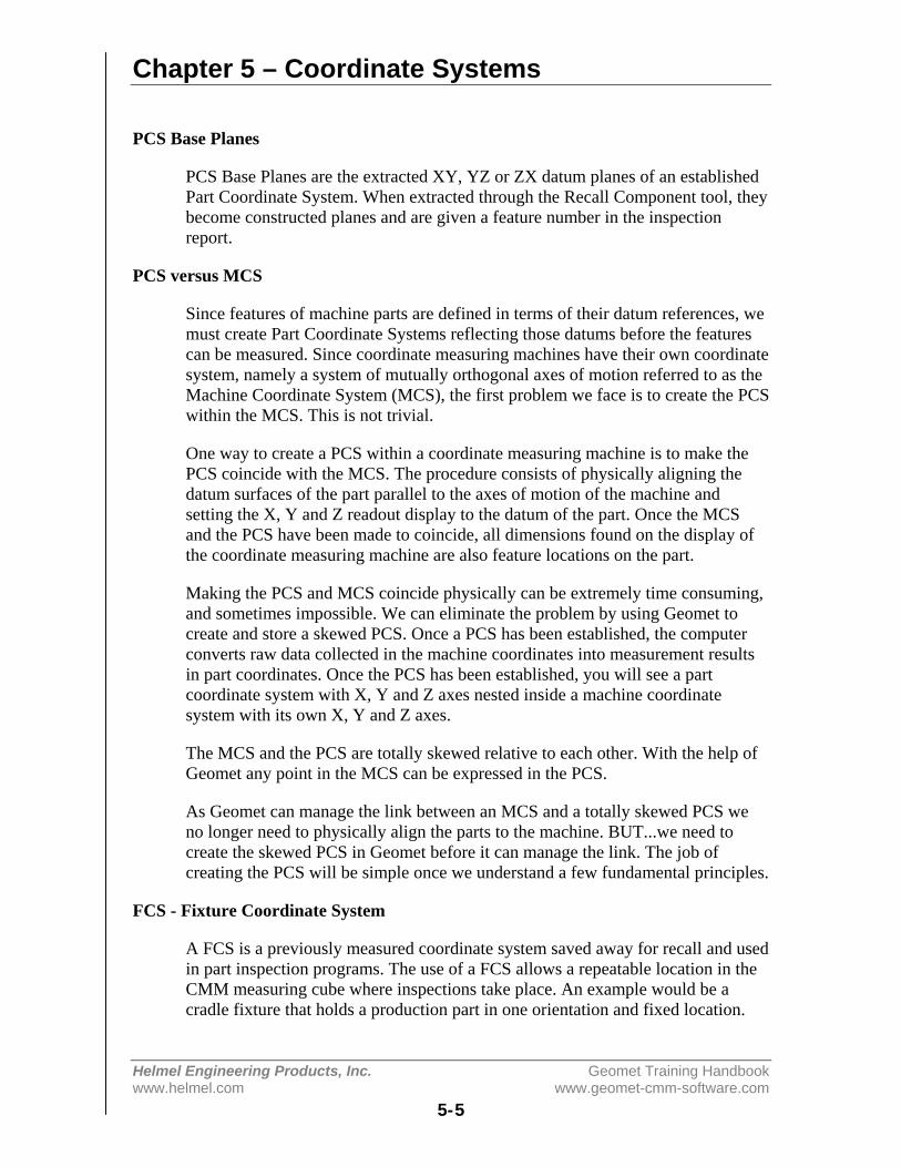
Chapter 5 – Coordinate Systems
Helmel Engineering Products, Inc. Geomet Training Handbookwww.helmel.com www.geomet-cmm-software.com
5-5
PCS Base Planes
PCS Base Planes are the extracted XY, YZ or ZX datum planes of an establishedPart Coordinate System. When extracted through the Recall Component tool, theybecome constructed planes and are given a feature number in the inspectionreport.
PCS versus MCS
Since features of machine parts are defined in terms of their datum references, wemust create Part Coordinate Systems reflecting those datums before the featurescan be measured. Since coordinate measuring machines have their own coordinatesystem, namely a system of mutually orthogonal axes of motion referred to as theMachine Coordinate System (MCS), the first problem we face is to create the PCSwithin the MCS. This is not trivial.
One way to create a PCS within a coordinate measuring machine is to make thePCS coincide with the MCS. The procedure consists of physically aligning thedatum surfaces of the part parallel to the axes of motion of the machine andsetting the X, Y and Z readout display to the datum of the part. Once the MCSand the PCS have been made to coincide, all dimensions found on the display ofthe coordinate measuring machine are also feature locations on the part.
Making the PCS and MCS coincide physically can be extremely time consuming,and sometimes impossible. We can eliminate the problem by using Geomet tocreate and store a skewed PCS. Once a PCS has been established, the computerconverts raw data collected in the machine coordinates into measurement resultsin part coordinates. Once the PCS has been established, you will see a partcoordinate system with X, Y and Z axes nested inside a machine coordinatesystem with its own X, Y and Z axes.
The MCS and the PCS are totally skewed relative to each other. With the help ofGeomet any point in the MCS can be expressed in the PCS.
As Geomet can manage the link between an MCS and a totally skewed PCS weno longer need to physically align the parts to the machine. BUT...we need tocreate the skewed PCS in Geomet before it can manage the link. The job ofcreating the PCS will be simple once we understand a few fundamental principles.
FCS - Fixture Coordinate System
A FCS is a previously measured coordinate system saved away for recall and usedin part inspection programs. The use of a FCS allows a repeatable location in theCMM measuring cube where inspections take place. An example would be acradle fixture that holds a production part in one orientation and fixed location.
Chapter 5 – Coordinate Systems
Helmel Engineering Products, Inc. Geomet Training Handbookwww.helmel.com www.geomet-cmm-software.com
5-6
The use of a FCS requires that the CMM has a known home position, which iscommon on all DCC CMMs and on few manual CMMs.
The process of creating an FCS entails establishing a PCS on the fixture and thenactivating the FCS Manager to append the specific geometry values associatedwith the established PCS to the FCS database. Using an FCS requires recalling theFCS by the assigned number through the Coordinate System Manager.
ICS - Interim Coordinate System
The ICS is a coordinate system that has not been completed to the status of a PCS.For example, when Geomet begins a part inspection, the only coordinate systemavailable is the MCS. Should the part to be inspected have the orient applied to it,Geomet creates an ICS based on the orient vector data and brings forward thealignment and origin data from the MCS.
During the inspection process, reported results on features are hidden until thePCS is completed. Only then will the reported data be meaningful.
CCS - Clearance Coordinate Systems
A Clearance Coordinate System creates safe zones around the part beinginspected and around any fixtures associated with the inspection. The ClearanceCS contains 3 clearance planes, identified as XY, YZ and ZX base planes and anorigin. These clearance planes are used as safe transition planes where the CMMcan perform DCC moves without concern of accidental probe encounters.Clearance CSs are used with Auto-IPs and Entry / Exit IPs in auto features.
WCS – Wobble Coordinate System
The Wobble Coordinate System is used exclusively with a rotary motorized axismounted on a 3-Axis CMM providing 4-axes of control. The use of a WCS allowsthe PCS to be rotated as the part is rotated without having to reestablish the PCS.
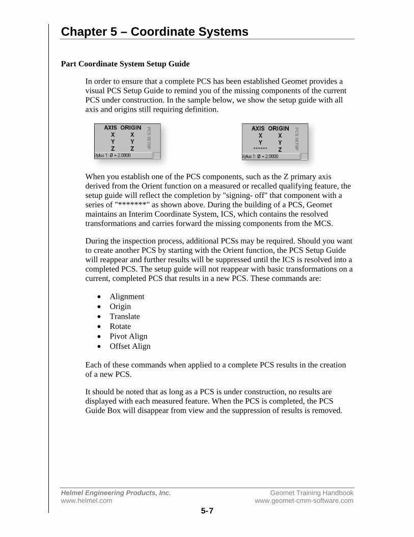
Chapter 5 – Coordinate Systems
Helmel Engineering Products, Inc. Geomet Training Handbookwww.helmel.com www.geomet-cmm-software.com
5-7
Part Coordinate System Setup Guide
In order to ensure that a complete PCS has been established Geomet provides avisual PCS Setup Guide to remind you of the missing components of the currentPCS under construction. In the sample below, we show the setup guide with allaxis and origins still requiring definition.
When you establish one of the PCS components, such as the Z primary axisderived from the Orient function on a measured or recalled qualifying feature, thesetup guide will reflect the completion by "signing- off" that component with aseries of "*******" as shown above. During the building of a PCS, Geometmaintains an Interim Coordinate System, ICS, which contains the resolvedtransformations and carries forward the missing components from the MCS.
During the inspection process, additional PCSs may be required. Should you wantto create another PCS by starting with the Orient function, the PCS Setup Guidewill reappear and further results will be suppressed until the ICS is resolved into acompleted PCS. The setup guide will not reappear with basic transformations on acurrent, completed PCS that results in a new PCS. These commands are:
• Alignment• Origin• Translate• Rotate• Pivot Align• Offset Align
Each of these commands when applied to a complete PCS results in the creationof a new PCS.
It should be noted that as long as a PCS is under construction, no results aredisplayed with each measured feature. When the PCS is completed, the PCSGuide Box will disappear from view and the suppression of results is removed.
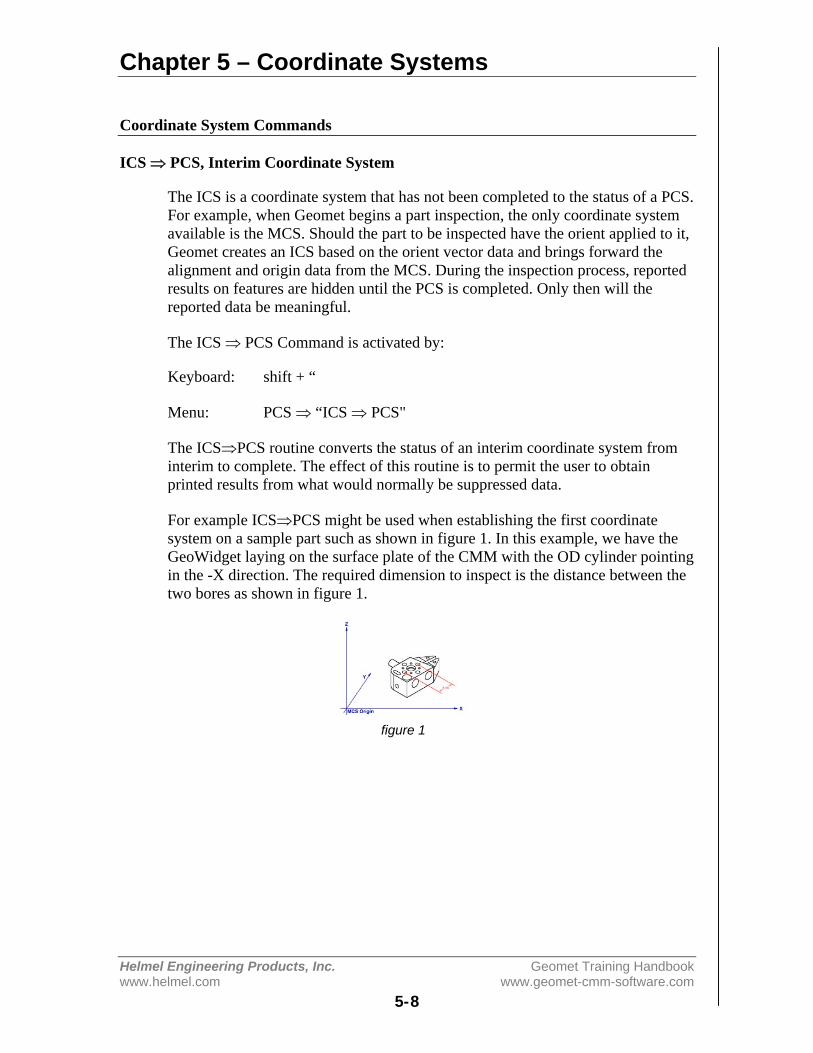
Chapter 5 – Coordinate Systems
Helmel Engineering Products, Inc. Geomet Training Handbookwww.helmel.com www.geomet-cmm-software.com
5-8
Coordinate System Commands
ICS ⇒ PCS, Interim Coordinate System
The ICS is a coordinate system that has not been completed to the status of a PCS.For example, when Geomet begins a part inspection, the only coordinate systemavailable is the MCS. Should the part to be inspected have the orient applied to it,Geomet creates an ICS based on the orient vector data and brings forward thealignment and origin data from the MCS. During the inspection process, reportedresults on features are hidden until the PCS is completed. Only then will thereported data be meaningful.
The ICS ⇒ PCS Command is activated by:
Keyboard: shift + “
Menu: PCS ⇒ “ICS ⇒ PCS"
The ICS⇒PCS routine converts the status of an interim coordinate system frominterim to complete. The effect of this routine is to permit the user to obtainprinted results from what would normally be suppressed data.
For example ICS⇒PCS might be used when establishing the first coordinatesystem on a sample part such as shown in figure 1. In this example, we have theGeoWidget laying on the surface plate of the CMM with the OD cylinder pointingin the -X direction. The required dimension to inspect is the distance between thetwo bores as shown in figure 1.
figure 1
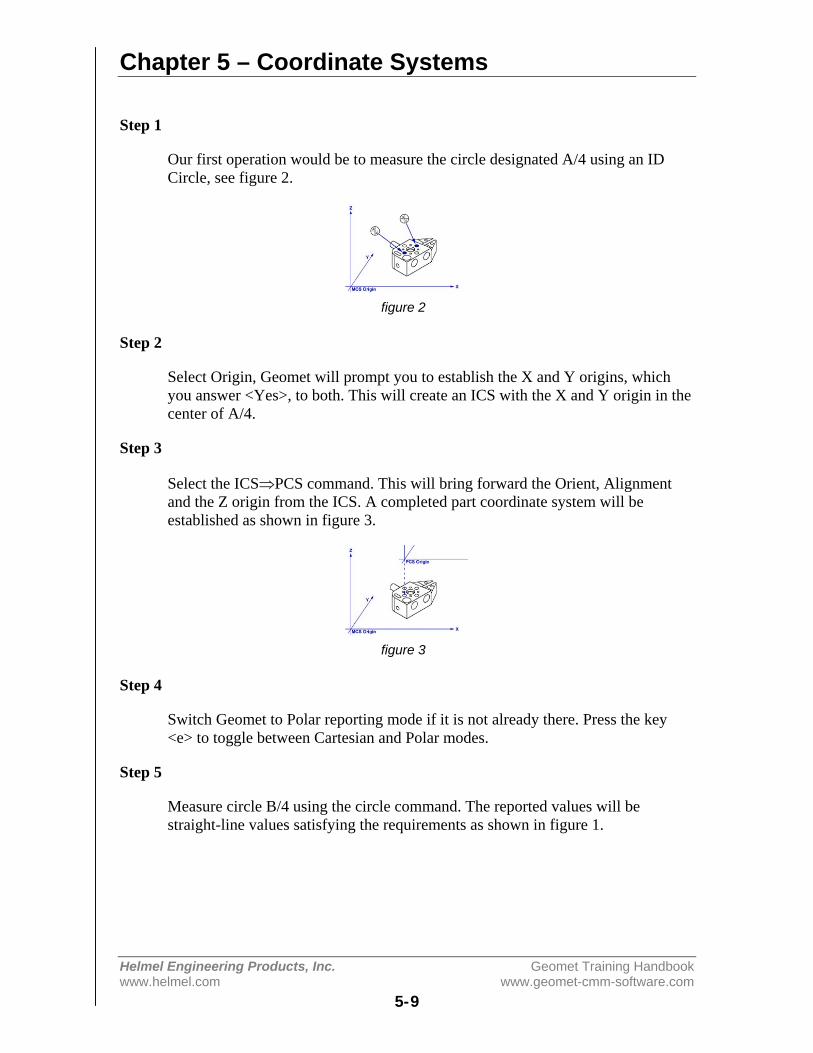
Chapter 5 – Coordinate Systems
Helmel Engineering Products, Inc. Geomet Training Handbookwww.helmel.com www.geomet-cmm-software.com
5-9
Step 1
Our first operation would be to measure the circle designated A/4 using an IDCircle, see figure 2.
figure 2
Step 2
Select Origin, Geomet will prompt you to establish the X and Y origins, whichyou answer <Yes>, to both. This will create an ICS with the X and Y origin in thecenter of A/4.
Step 3
Select the ICS⇒PCS command. This will bring forward the Orient, Alignmentand the Z origin from the ICS. A completed part coordinate system will beestablished as shown in figure 3.
figure 3
Step 4
Switch Geomet to Polar reporting mode if it is not already there. Press the key<e> to toggle between Cartesian and Polar modes.
Step 5
Measure circle B/4 using the circle command. The reported values will bestraight-line values satisfying the requirements as shown in figure 1.
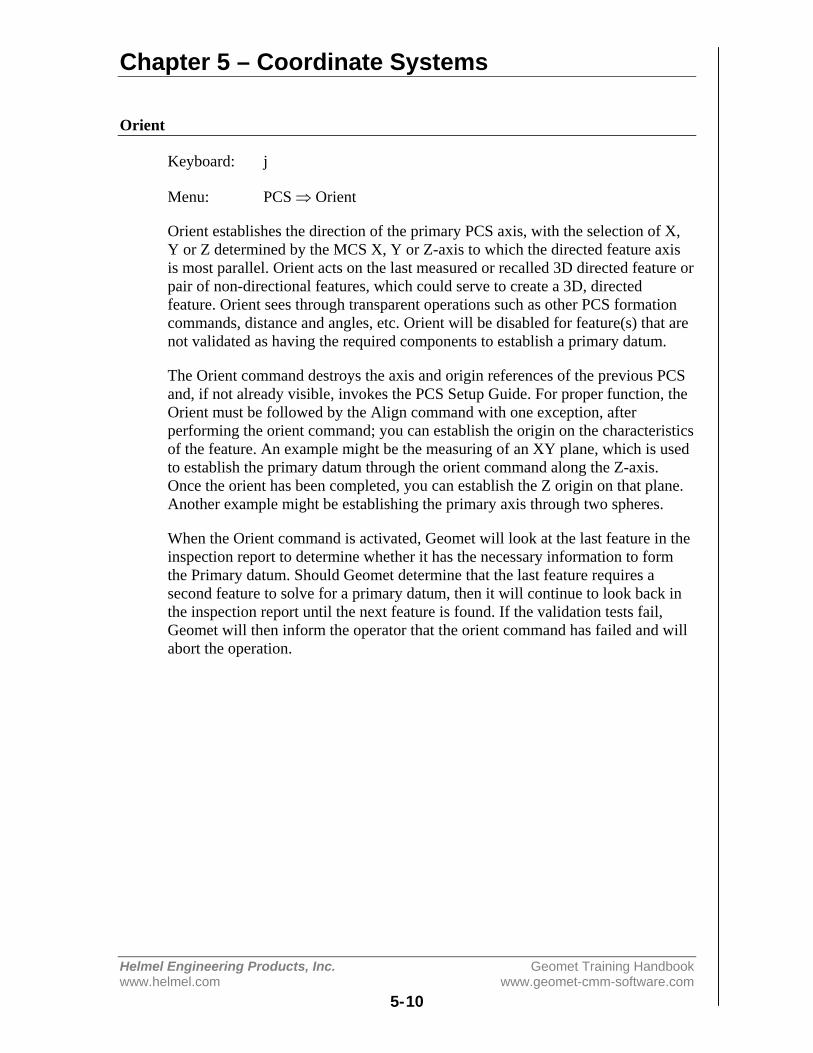
Chapter 5 – Coordinate Systems
Helmel Engineering Products, Inc. Geomet Training Handbookwww.helmel.com www.geomet-cmm-software.com
5-10
Orient
Keyboard: j
Menu: PCS ⇒ Orient
Orient establishes the direction of the primary PCS axis, with the selection of X,Y or Z determined by the MCS X, Y or Z-axis to which the directed feature axisis most parallel. Orient acts on the last measured or recalled 3D directed feature orpair of non-directional features, which could serve to create a 3D, directedfeature. Orient sees through transparent operations such as other PCS formationcommands, distance and angles, etc. Orient will be disabled for feature(s) that arenot validated as having the required components to establish a primary datum.
The Orient command destroys the axis and origin references of the previous PCSand, if not already visible, invokes the PCS Setup Guide. For proper function, theOrient must be followed by the Align command with one exception, afterperforming the orient command; you can establish the origin on the characteristicsof the feature. An example might be the measuring of an XY plane, which is usedto establish the primary datum through the orient command along the Z-axis.Once the orient has been completed, you can establish the Z origin on that plane.Another example might be establishing the primary axis through two spheres.
When the Orient command is activated, Geomet will look at the last feature in theinspection report to determine whether it has the necessary information to formthe Primary datum. Should Geomet determine that the last feature requires asecond feature to solve for a primary datum, then it will continue to look back inthe inspection report until the next feature is found. If the validation tests fail,Geomet will then inform the operator that the orient command has failed and willabort the operation.
Chapter 5 – Coordinate Systems
Helmel Engineering Products, Inc. Geomet Training Handbookwww.helmel.com www.geomet-cmm-software.com
5-11
Align
Keyboard: k
Menu: PCS ⇒ Align
Align establishes the directions of the secondary and tertiary PCS axes, with theselection of X, Y and Z determined by the MCS X, Y or Z axis to which thedirected feature axis is most parallel. Align acts on the last measured or recalled3D or 2D directed feature or pair of non-directed features which could serve tocreate a 2D or a 3D directed feature. For example, a pair of 1D co-directionalpoints, pairs of coplanar 2D points, or pairs of 3D points. The Align commandwill see through transparent operations such as other PCS formation commands,distance, angle commands, etc. Geomet will validate the last feature(s) todetermine whether they are capable of providing a secondary datum.
Align, when executed in an ICS directly after the orient has been established,makes an automatic choice for the alignment axis. For example, if the orientcommand resulted in establishing the Z-axis, then the Align command will rotateabout the Z to establish the secondary datum.
When the Align command is executed in an established PCS, the resultingoperation creates a new PCS by aligning to the requested feature. The Aligncommand will determine the alignment axis when a pair of co-directional 1Dpoints or coplanar 2D features is used. When using a pair of 3D features or a 3Daxial feature, Geomet will prompt for the PCS base plane to align in.

Chapter 5 – Coordinate Systems
Helmel Engineering Products, Inc. Geomet Training Handbookwww.helmel.com www.geomet-cmm-software.com
5-12
Origin
Keyboard: l (lower case L)
Menu: PCS ⇒ Origin
The Origin command builds the tertiary datum on the location of the lastmeasured or recalled feature. In the case of features with 1D locations such as 1Dpoints and planes the origin is established for the reported direction of the feature.
Using a +X 1D Point, the Origin command will set the reported position along theX-axis as the new X-axis origin leaving Y and Z untouched. For a –Z Plane, theZ-axis Origin is set where the plane crosses the existing Z-axis.
For 2D and 3D features, the Origin command will prompt you to choose whichaxis to set. On a 2D XY Circle, you may elect to set the X-axis and not the Y-axis.
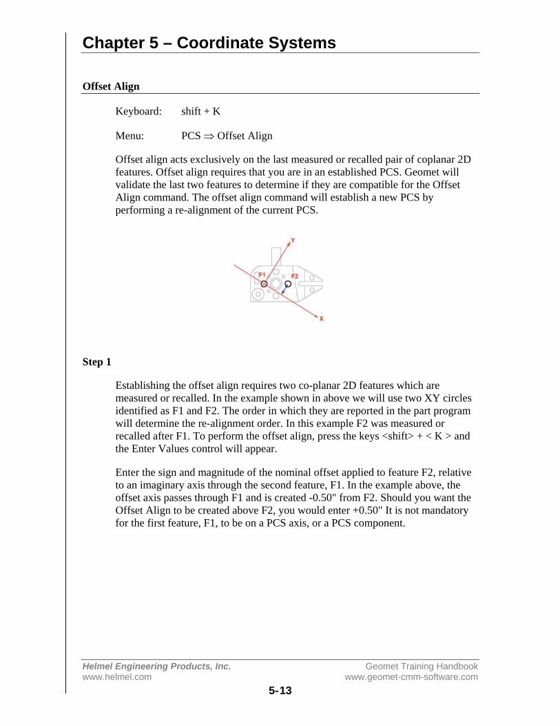
Chapter 5 – Coordinate Systems
Helmel Engineering Products, Inc. Geomet Training Handbookwww.helmel.com www.geomet-cmm-software.com
5-13
Offset Align
Keyboard: shift + K
Menu: PCS ⇒ Offset Align
Offset align acts exclusively on the last measured or recalled pair of coplanar 2Dfeatures. Offset align requires that you are in an established PCS. Geomet willvalidate the last two features to determine if they are compatible for the OffsetAlign command. The offset align command will establish a new PCS byperforming a re-alignment of the current PCS.
Step 1
Establishing the offset align requires two co-planar 2D features which aremeasured or recalled. In the example shown in above we will use two XY circlesidentified as F1 and F2. The order in which they are reported in the part programwill determine the re-alignment order. In this example F2 was measured orrecalled after F1. To perform the offset align, press the keys <shift> + < K > andthe Enter Values control will appear.
Enter the sign and magnitude of the nominal offset applied to feature F2, relativeto an imaginary axis through the second feature, F1. In the example above, theoffset axis passes through F1 and is created -0.50" from F2. Should you want theOffset Align to be created above F2, you would enter +0.50" It is not mandatoryfor the first feature, F1, to be on a PCS axis, or a PCS component.

Chapter 5 – Coordinate Systems
Helmel Engineering Products, Inc. Geomet Training Handbookwww.helmel.com www.geomet-cmm-software.com
5-14
Editing an Offset Align Feature
An Offset Alignment procedure once applied creates a new Part CoordinateSystem. You may edit the existing offset value when there are features using thePCS created by an offset align, but a warning is provided to rebuild all coordinatesystems by running the program from the beginning.
To edit the existing offset value, highlight that feature in the report, and bring upthe right-click sub menu. The ability to edit a translated feature is only availablewhen the translate feature has absolute entered values, not values derived from thelast feature option.
Enter the new offset value in the space provided and press the <Ok> button.Geomet will display a warning that the features will no longer have validpositional data after the Offset Align editing is completed. At this time, save thepart inspection file and run the file to rebuild the Part Coordinate Changes beforeadding any new steps to the program.

Chapter 5 – Coordinate Systems
Helmel Engineering Products, Inc. Geomet Training Handbookwww.helmel.com www.geomet-cmm-software.com
5-15
Pivot Align
Keyboard: Ctrl + k
Menu: PCS ⇒ Pivot Align
Pivot Align acts exclusively on the last 2D or 3D measured or recalled feature.Pivot align requires that you are not in an ICS and through Geomet validationprocedures, this command will be disabled. The pivot align command willperform a re-alignment of the current PCS.
Pivot Align with 2D Features
To perform a pivot align using a 2D feature, press the pivot align key < Ctrl + k >.Geomet will automatically re-align the current PCS through the existing originand the last 2D feature in your report database. In the example shown below, thelast feature is an XY circle identified as F1. The re-alignment takes place throughthe current PCS origin and the center of the circle, F1.
Pivot Align with 3D Features
To perform a pivot align using a 3D feature such as a 3D point or sphere, pressthe pivot align key < Ctrl > + < k >. Geomet validates the last feature and afteridentifying it as a 3D feature, prompts you to select a PCS base axis to rotateabout. For example, if you are to perform a pivot align using a sphere, you will beprompted to select a PCS base axis. The base axis represents the normal axis tothe base plane the re-alignment will take place in. If you selected the Z, The pivotalign will take place in the XY base plane and the projected XY components ofthe sphere will act as the 2D point through which the re-alignment will take place.
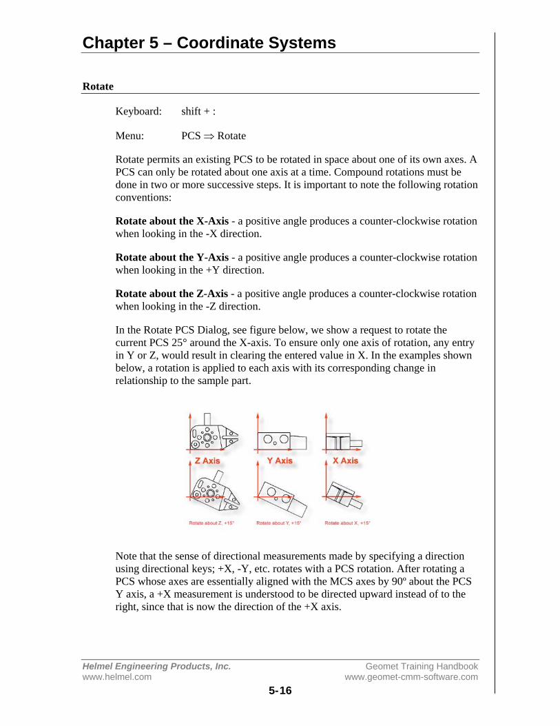
Chapter 5 – Coordinate Systems
Helmel Engineering Products, Inc. Geomet Training Handbookwww.helmel.com www.geomet-cmm-software.com
5-16
Rotate
Keyboard: shift + :
Menu: PCS ⇒ Rotate
Rotate permits an existing PCS to be rotated in space about one of its own axes. APCS can only be rotated about one axis at a time. Compound rotations must bedone in two or more successive steps. It is important to note the following rotationconventions:
Rotate about the X-Axis - a positive angle produces a counter-clockwise rotationwhen looking in the -X direction.
Rotate about the Y-Axis - a positive angle produces a counter-clockwise rotationwhen looking in the +Y direction.
Rotate about the Z-Axis - a positive angle produces a counter-clockwise rotationwhen looking in the -Z direction.
In the Rotate PCS Dialog, see figure below, we show a request to rotate thecurrent PCS 25° around the X-axis. To ensure only one axis of rotation, any entryin Y or Z, would result in clearing the entered value in X. In the examples shownbelow, a rotation is applied to each axis with its corresponding change inrelationship to the sample part.
Note that the sense of directional measurements made by specifying a directionusing directional keys; +X, -Y, etc. rotates with a PCS rotation. After rotating aPCS whose axes are essentially aligned with the MCS axes by 90º about the PCSY axis, a +X measurement is understood to be directed upward instead of to theright, since that is now the direction of the +X axis.

Chapter 5 – Coordinate Systems
Helmel Engineering Products, Inc. Geomet Training Handbookwww.helmel.com www.geomet-cmm-software.com
5-17
Edit an Existing Rotation Value
A Rotate PCS feature once applied creates a new Part Coordinate System. Youmay edit the existing rotation value when there are features using the rotated PCS,but a warning is provided to rebuild all coordinate systems by running theprogram from the beginning.
To edit the existing rotation feature, highlight that feature and bring up the right-click sub menu. From the sub menu, select Edit Rotate Values. NOTE: The abilityto edit a translated feature is only available when the translate feature has absoluteentered values, not values derived from the last feature option.
Enter the new rotate value in the space provided and press the <Ok> button.Geomet will display a warning that the features will no longer have validpositional data after the edit of the rotation values is completed. At this time, savethe part inspection file and run the file to rebuild the Part Coordinate Changes.
Chapter 5 – Coordinate Systems
Helmel Engineering Products, Inc. Geomet Training Handbookwww.helmel.com www.geomet-cmm-software.com
5-18
Translate
Keyboard: ;
Menu: PCS ⇒ Translate
Translate permits an existing PCS origin to be shifted by nominal amounts in allthree directions. Translation creates a new complete PCS whose axes are parallelto those of the preceding PCS but shifted by the input values.
To perform a Translate, activate the Translate tool using the keyboard “;” or [PCS⇒ Translate] from the drop down menus. Geomet offers two methods to performa PCS Origin Translation. The first method uses XYZ incremental values totranslate the current origin, which are entered by the operator. To use this method,place a bullet next to the "Enter Values" entry in the Translation Source groupbox.
To translate absolute values, enter the required absolute values in the X, Y and Zedit controls provided. You can translate 1, 2 or 3 axis with one translatecommand. Upon completion, a new PCS is established using the next availablePCS ID number.
In the “Use Last Feature” method, we can obtain a feature specific value such asthe radius of the previously measured circle. Qualifying features include Circle,Cylinder, Cone and Sphere. When you place a bullet next to "Use Last Feature",Geomet will show the radius value in the Translation Source box under "Use LastFeature".
The ( - ) and ( + ) column will become active next to the data fields. You can thencheck the appropriate directions you wish to translate in. Should you not want totranslate in any axis, leave the check marks unchecked.
An example would be when the origin is called out on a tangent point of a circle.After you have established the Orient and Align Axis, measure the circle andplace the origin in the center. Then perform a PCS Translate using the last featureoption. Select the appropriate direction under the ( - ) and ( + ) columns. Afteraccepting the translation, the new origin will be on the tangent point of the circle.

Chapter 5 – Coordinate Systems
Helmel Engineering Products, Inc. Geomet Training Handbookwww.helmel.com www.geomet-cmm-software.com
5-19
Both methods will create a new PCS. To summarize the methods, when "EnterValues" is selected, the values entered by the operator are considered absolute andwill carry forward with each successive inspection run. Selecting "Use LastFeature" the translation values will recalculate with each inspection run and areconsidered dynamic to the current inspection run.
Edit an Existing Translation Value
A Translate feature once applied creates a new Part Coordinate System. You mayedit the existing translation values when there are features using the translatedPCS, but a warning is provided to rebuild all coordinate systems by running theprogram from the beginning.
To edit the existing translation feature, highlight that feature and bring up theright-click sub menu. NOTE: The ability to edit a translated feature is onlyavailable when the translate feature has absolute entered values, not valuesderived from the last feature option.
Enter the new translation values in the space provided and press the <Ok> button.Geomet will display a warning that the features will no longer have validpositional data after the editing of translation values has been completed. At thistime, save the part inspection file and run the file to rebuild the Part CoordinateChanges.
Chapter 5 – Coordinate Systems
Helmel Engineering Products, Inc. Geomet Training Handbookwww.helmel.com www.geomet-cmm-software.com
5-20
PCS Program Examples
Here you will find 12 Part Coordinate Examples to assist your learning of theprocesses used for measuring features and applying them to the building of a PartCoordinate System. On the Geomet web site, these examples can be downloadedto view the end results on your system.
Try each example and compare your final results with that of our suppliedexamples.
PCS Program Examples#1, Basic Alignment#2, Plane-Line-Point#3, Quick PCS#4, Plane-Circle-Circle#5, Plane-Cylinder-Circle#6, Plane-Bisect Points-Circle#7, Cylinder-Circle-Point#8, Plane-Intersect Lines-Bisect Points-Circle#9, Offset Alignment#10, Pivot Alignment#11, Translate#12, Rotate
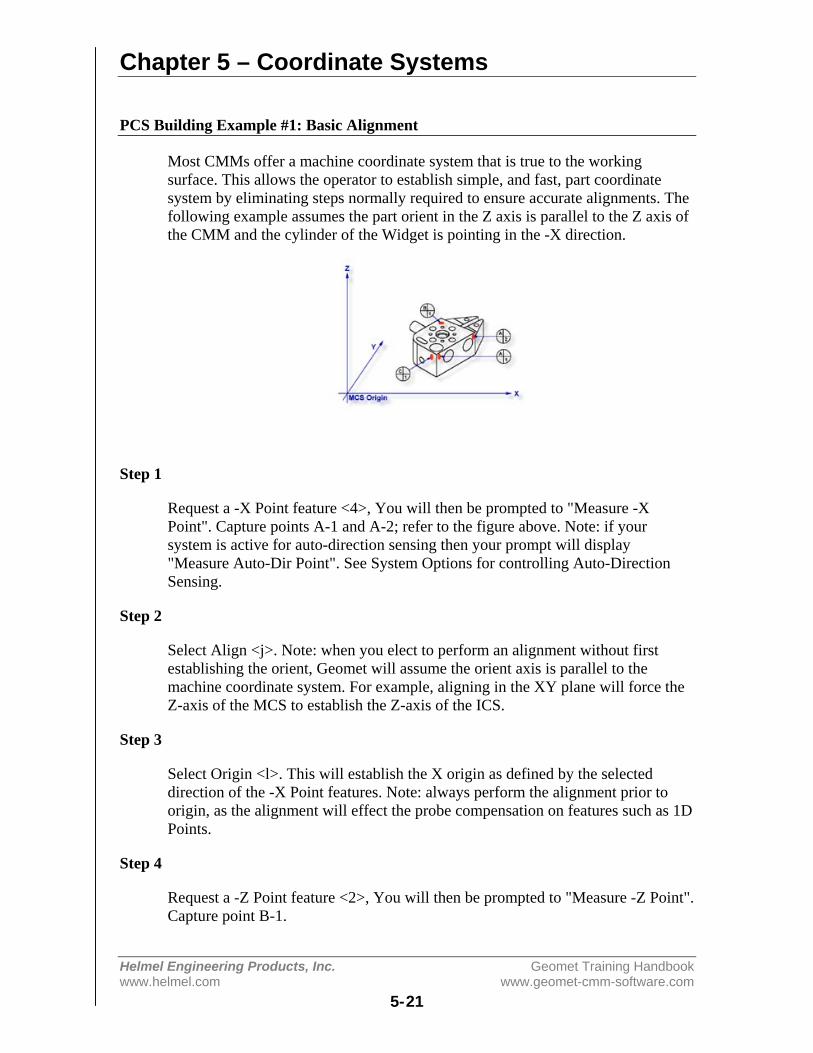
Chapter 5 – Coordinate Systems
Helmel Engineering Products, Inc. Geomet Training Handbookwww.helmel.com www.geomet-cmm-software.com
5-21
PCS Building Example #1: Basic Alignment
Most CMMs offer a machine coordinate system that is true to the workingsurface. This allows the operator to establish simple, and fast, part coordinatesystem by eliminating steps normally required to ensure accurate alignments. Thefollowing example assumes the part orient in the Z axis is parallel to the Z axis ofthe CMM and the cylinder of the Widget is pointing in the -X direction.
Step 1
Request a -X Point feature <4>, You will then be prompted to "Measure -XPoint". Capture points A-1 and A-2; refer to the figure above. Note: if yoursystem is active for auto-direction sensing then your prompt will display"Measure Auto-Dir Point". See System Options for controlling Auto-DirectionSensing.
Step 2
Select Align <j>. Note: when you elect to perform an alignment without firstestablishing the orient, Geomet will assume the orient axis is parallel to themachine coordinate system. For example, aligning in the XY plane will force theZ-axis of the MCS to establish the Z-axis of the ICS.
Step 3
Select Origin <l>. This will establish the X origin as defined by the selecteddirection of the -X Point features. Note: always perform the alignment prior toorigin, as the alignment will effect the probe compensation on features such as 1DPoints.
Step 4
Request a -Z Point feature <2>, You will then be prompted to "Measure -Z Point".Capture point B-1.
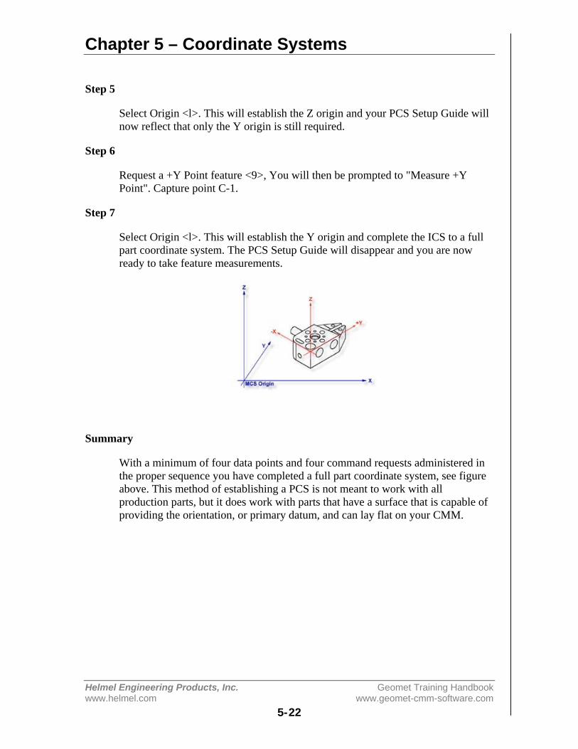
Chapter 5 – Coordinate Systems
Helmel Engineering Products, Inc. Geomet Training Handbookwww.helmel.com www.geomet-cmm-software.com
5-22
Step 5
Select Origin <l>. This will establish the Z origin and your PCS Setup Guide willnow reflect that only the Y origin is still required.
Step 6
Request a +Y Point feature <9>, You will then be prompted to "Measure +YPoint". Capture point C-1.
Step 7
Select Origin <l>. This will establish the Y origin and complete the ICS to a fullpart coordinate system. The PCS Setup Guide will disappear and you are nowready to take feature measurements.
Summary
With a minimum of four data points and four command requests administered inthe proper sequence you have completed a full part coordinate system, see figureabove. This method of establishing a PCS is not meant to work with allproduction parts, but it does work with parts that have a surface that is capable ofproviding the orientation, or primary datum, and can lay flat on your CMM.
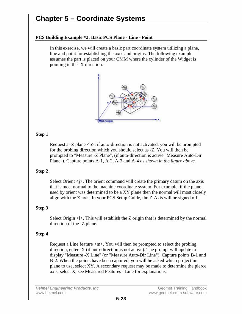
Chapter 5 – Coordinate Systems
Helmel Engineering Products, Inc. Geomet Training Handbookwww.helmel.com www.geomet-cmm-software.com
5-23
PCS Building Example #2: Basic PCS Plane - Line - Point
In this exercise, we will create a basic part coordinate system utilizing a plane,line and point for establishing the axes and origins. The following exampleassumes the part is placed on your CMM where the cylinder of the Widget ispointing in the -X direction.
Step 1
Request a -Z plane <b>, if auto-direction is not activated, you will be promptedfor the probing direction which you should select as -Z. You will then beprompted to "Measure -Z Plane", (if auto-direction is active "Measure Auto-DirPlane"). Capture points A-1, A-2, A-3 and A-4 as shown in the figure above.
Step 2
Select Orient <j>. The orient command will create the primary datum on the axisthat is most normal to the machine coordinate system. For example, if the planeused by orient was determined to be a XY plane then the normal will most closelyalign with the Z-axis. In your PCS Setup Guide, the Z-Axis will be signed off.
Step 3
Select Origin <l>. This will establish the Z origin that is determined by the normaldirection of the -Z plane.
Step 4
Request a Line feature <m>, You will then be prompted to select the probingdirection, enter -X (if auto-direction is not active). The prompt will update todisplay "Measure -X Line" (or "Measure Auto-Dir Line"). Capture points B-1 andB-2. When the points have been captured, you will be asked which projectionplane to use, select XY. A secondary request may be made to determine the pierceaxis, select X, see Measured Features - Line for explanations.
Chapter 5 – Coordinate Systems
Helmel Engineering Products, Inc. Geomet Training Handbookwww.helmel.com www.geomet-cmm-software.com
5-24
Step 5
Select Align <k>. Your ICS will update to include the secondary datum that isderived from the XY line feature.
Step 6
Select Origin <l>. This will establish the X origin that is determined by thereported direction of the XY Line.
Step 7
Request a +Y Point feature <9>, You will then be prompted to "Measure +YPoint". Capture point C-1.
Step 8
Select Origin <l>. This will establish the Y origin and complete the ICS to a fullpart coordinate system. The PCS Setup Guide will disappear and you are nowready to take feature measurements.
Summary
The Plane-Line-Point combinations of features are commonly used for mostmachined parts to set the part coordinate system. It is important to remember thatthe features in these exercises are utilizing minimum data points to achieve acomplete PCS. There are several factors that can negatively effect the quality ofyour data points. These include probing speed and distance between data pointsjust to name two.
In the case of the alignment, we used two points to calculate the line. Therepeatability of the electronic trigger probe can be as much as .00014" with astandard 20 mm extension. If the two points for the line were taken 0.500" apart,the possibility exists of .00028" error per inch, when applied to the PCS effects allfeatures being measured. It is therefore important that you select the most stablefeatures to establish your PCS and balance the number of data points to helpreduce inherent CMM and operator errors. When possible, use more data points tohelp define the feature, especially when these features are used for establishingdatum features.

Chapter 5 – Coordinate Systems
Helmel Engineering Products, Inc. Geomet Training Handbookwww.helmel.com www.geomet-cmm-software.com
5-25
PCS Building Example #3: Quick PCS
In this exercise, you will utilize Geomet’s automatic part coordinate system tool,known as the Quick PCS. Quick PCS requires that you have auto-directioncapabilities and that it is active through [System Options⇒Enhanced Features].
The premise of Quick PCS is to perform the basic Plane and 3 - 1D Point setup tocreate a PCS without the operator commanding any feature requests. When youstart Geomet and establish the working stylus, Geomet is waiting for a data point.If it acknowledges an incoming data point and is not currently setup for a feature,it assumes you are invoking the Quick PCS option.
Step 1
Using the datum targets as shown in the figure above, gather data points A-1through A-4. Geomet will automatically establish a plane, orient and origin afterthe forth point has been captured.
Step 2
Gather data points B-1 and B-2 making sure you follow the rules on probing 1Dpoints using auto-direction, see Measured Features - Points. Once these twopoints are captured, Geomet will establish the alignment and origin based on thepoint directions.
Should the points be captured in such a way as to misidentify the direction, theQuick PCS tool will abort the auto sequence and return you to normal inspections.If this occurs, correct the point direction (see Measured Features - Points) andcontinue with the setup as described in exercise 2, steps 5 - 8.
Step 3
Capture the final data point, C-1 and Geomet will complete the final origin andestablish PCS 1.

Chapter 5 – Coordinate Systems
Helmel Engineering Products, Inc. Geomet Training Handbookwww.helmel.com www.geomet-cmm-software.com
5-26
Summary
With the Quick PCS feature of Geomet, you were not required to press anyfeature key or in any other way instruct Geomet of the next feature or action.

Chapter 5 – Coordinate Systems
Helmel Engineering Products, Inc. Geomet Training Handbookwww.helmel.com www.geomet-cmm-software.com
5-27
PCS Building Example #4: Plane - Circle - Circle
In this exercise, we will create a basic part coordinate system utilizing a plane andtwo circles for establishing the axes and origins. The following example assumesthe part is placed on your CMM where the cylinder of the Widget is pointing inthe -X direction.
Step 1
Request a -Z plane <b>, if auto-direction is not activated, you will be promptedfor the probing direction which you should select as -Z. You will then beprompted to "Measure -Z Plane", (if auto-direction is active "Measure Auto-DirPlane"). Capture points A-1, A-2, A-3 and A-4 as shown in the figure above.
Step 2
Select Orient <j>. The orient command will create the primary datum on the axisthat is most normal to the machine coordinate system. For example, if the planeused by orient was determined to be a XY plane then the normal will most closelyalign with the Z-axis. In your PCS Setup Guide, the Z-Axis will be signed off.
Step 3
Select Origin <l>. This will establish the Z origin that is determined by the normaldirection of the -Z plane.
Step 4
Select Circle <z>, if auto-direction is not activated, you will be prompted for theCircle types, ID OD IR OR, choose ID. Capture the four data points identified asB-ID/4. Continue with the data points for the next circle, C-ID/4.
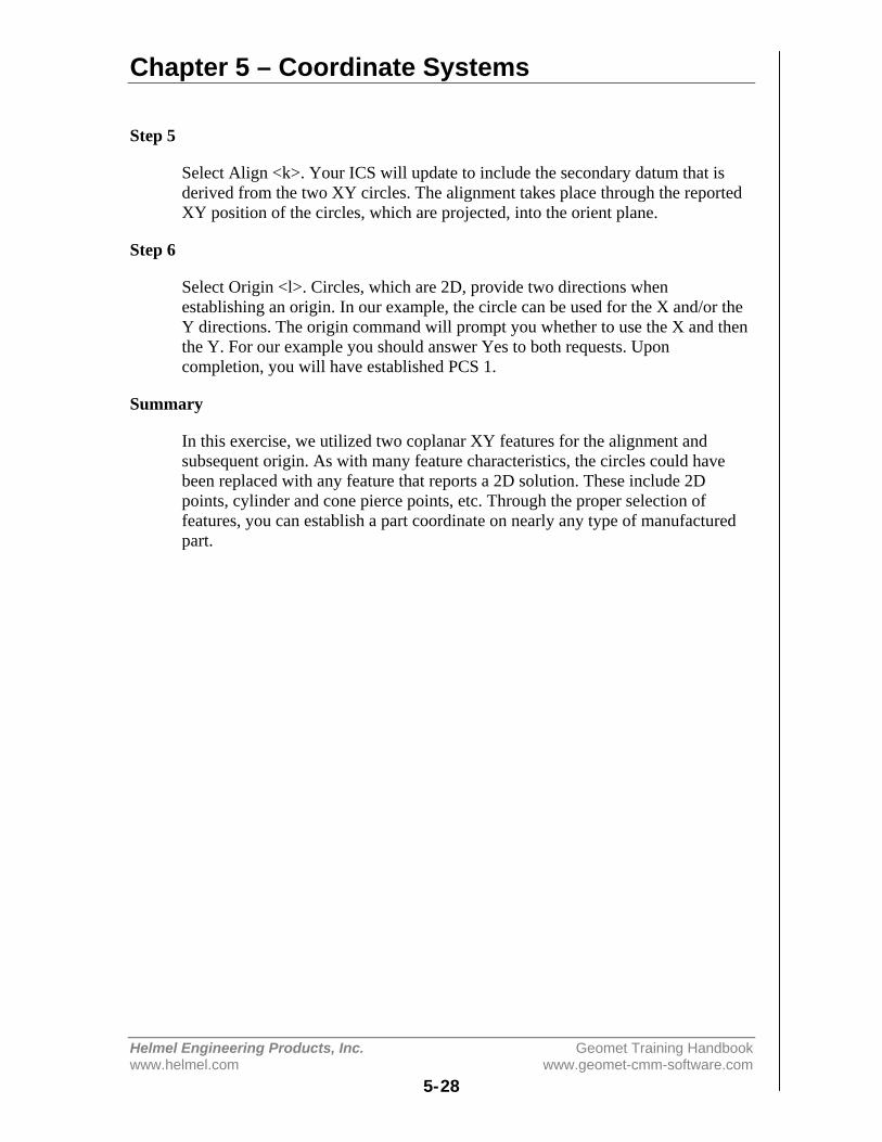
Chapter 5 – Coordinate Systems
Helmel Engineering Products, Inc. Geomet Training Handbookwww.helmel.com www.geomet-cmm-software.com
5-28
Step 5
Select Align <k>. Your ICS will update to include the secondary datum that isderived from the two XY circles. The alignment takes place through the reportedXY position of the circles, which are projected, into the orient plane.
Step 6
Select Origin <l>. Circles, which are 2D, provide two directions whenestablishing an origin. In our example, the circle can be used for the X and/or theY directions. The origin command will prompt you whether to use the X and thenthe Y. For our example you should answer Yes to both requests. Uponcompletion, you will have established PCS 1.
Summary
In this exercise, we utilized two coplanar XY features for the alignment andsubsequent origin. As with many feature characteristics, the circles could havebeen replaced with any feature that reports a 2D solution. These include 2Dpoints, cylinder and cone pierce points, etc. Through the proper selection offeatures, you can establish a part coordinate on nearly any type of manufacturedpart.
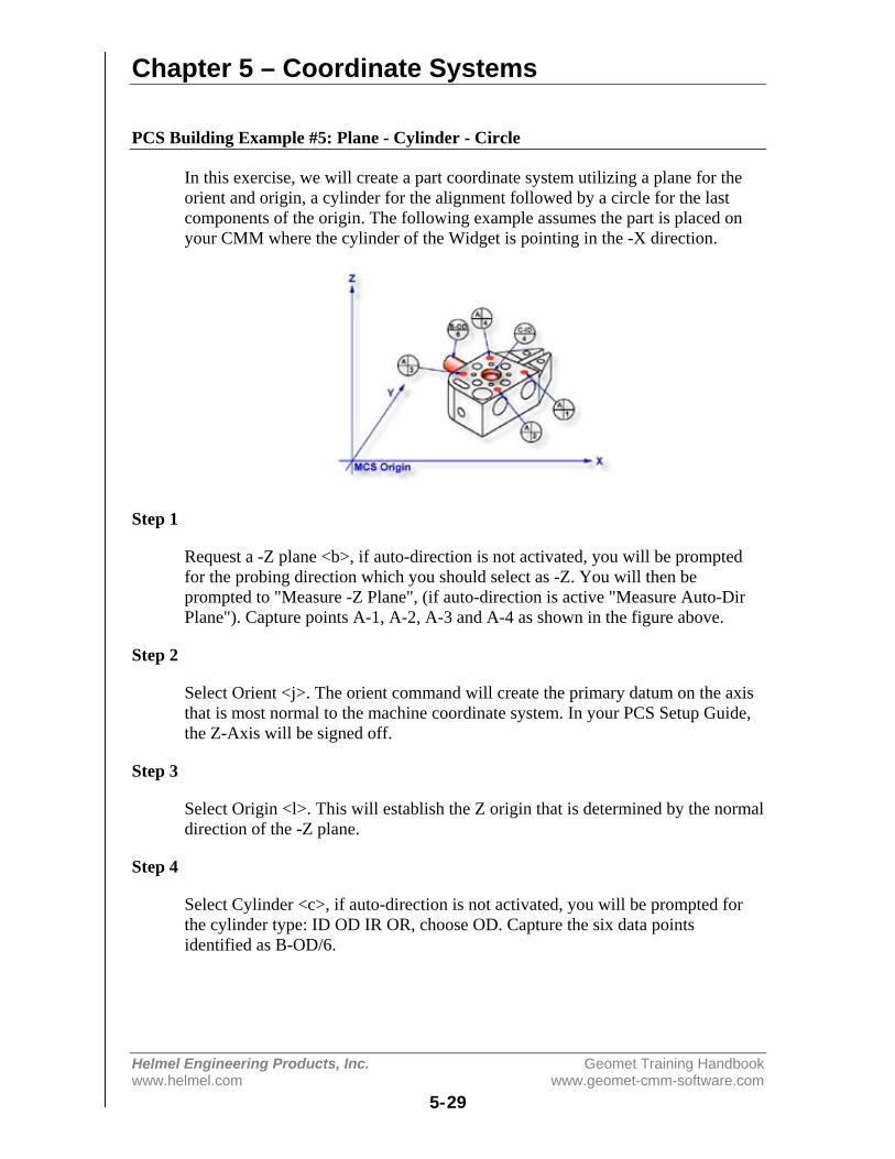
Chapter 5 – Coordinate Systems
Helmel Engineering Products, Inc. Geomet Training Handbookwww.helmel.com www.geomet-cmm-software.com
5-29
PCS Building Example #5: Plane - Cylinder - Circle
In this exercise, we will create a part coordinate system utilizing a plane for theorient and origin, a cylinder for the alignment followed by a circle for the lastcomponents of the origin. The following example assumes the part is placed onyour CMM where the cylinder of the Widget is pointing in the -X direction.
Step 1
Request a -Z plane <b>, if auto-direction is not activated, you will be promptedfor the probing direction which you should select as -Z. You will then beprompted to "Measure -Z Plane", (if auto-direction is active "Measure Auto-DirPlane"). Capture points A-1, A-2, A-3 and A-4 as shown in the figure above.
Step 2
Select Orient <j>. The orient command will create the primary datum on the axisthat is most normal to the machine coordinate system. In your PCS Setup Guide,the Z-Axis will be signed off.
Step 3
Select Origin <l>. This will establish the Z origin that is determined by the normaldirection of the -Z plane.
Step 4
Select Cylinder <c>, if auto-direction is not activated, you will be prompted forthe cylinder type: ID OD IR OR, choose OD. Capture the six data pointsidentified as B-OD/6.
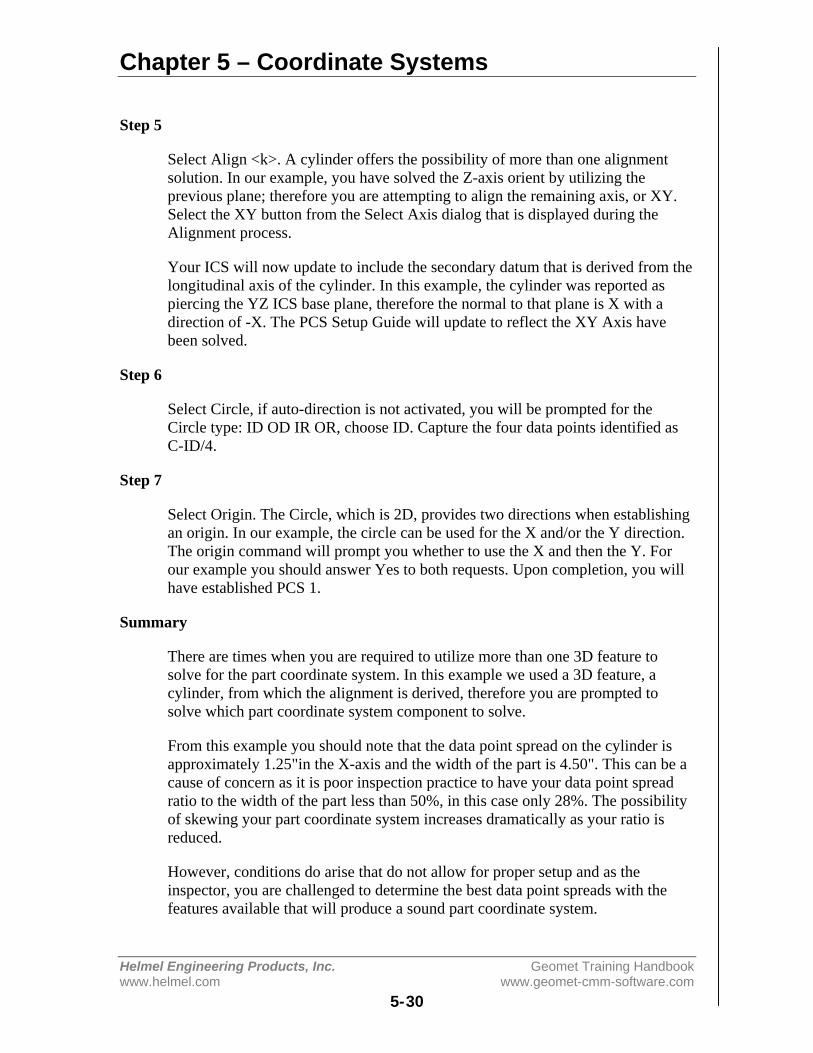
Chapter 5 – Coordinate Systems
Helmel Engineering Products, Inc. Geomet Training Handbookwww.helmel.com www.geomet-cmm-software.com
5-30
Step 5
Select Align <k>. A cylinder offers the possibility of more than one alignmentsolution. In our example, you have solved the Z-axis orient by utilizing theprevious plane; therefore you are attempting to align the remaining axis, or XY.Select the XY button from the Select Axis dialog that is displayed during theAlignment process.
Your ICS will now update to include the secondary datum that is derived from thelongitudinal axis of the cylinder. In this example, the cylinder was reported aspiercing the YZ ICS base plane, therefore the normal to that plane is X with adirection of -X. The PCS Setup Guide will update to reflect the XY Axis havebeen solved.
Step 6
Select Circle, if auto-direction is not activated, you will be prompted for theCircle type: ID OD IR OR, choose ID. Capture the four data points identified asC-ID/4.
Step 7
Select Origin. The Circle, which is 2D, provides two directions when establishingan origin. In our example, the circle can be used for the X and/or the Y direction.The origin command will prompt you whether to use the X and then the Y. Forour example you should answer Yes to both requests. Upon completion, you willhave established PCS 1.
Summary
There are times when you are required to utilize more than one 3D feature tosolve for the part coordinate system. In this example we used a 3D feature, acylinder, from which the alignment is derived, therefore you are prompted tosolve which part coordinate system component to solve.
From this example you should note that the data point spread on the cylinder isapproximately 1.25"in the X-axis and the width of the part is 4.50". This can be acause of concern as it is poor inspection practice to have your data point spreadratio to the width of the part less than 50%, in this case only 28%. The possibilityof skewing your part coordinate system increases dramatically as your ratio isreduced.
However, conditions do arise that do not allow for proper setup and as theinspector, you are challenged to determine the best data point spreads with thefeatures available that will produce a sound part coordinate system.

Chapter 5 – Coordinate Systems
Helmel Engineering Products, Inc. Geomet Training Handbookwww.helmel.com www.geomet-cmm-software.com
5-31
PCS Building Example #6: Plane - Bisect Points - Circle
In this exercise, we will create a part coordinate system utilizing a plane for theorient and origin, two 2D points from which we will obtain a constructed 2Dpoint through the bisect command then followed by a circle for alignment andorigin. The following example assumes the part is placed on your CMM wherethe cylinder of the Widget is pointing in the -X direction.
Step 1
Request a -Z plane <b>, if auto-direction is not activated, you will be asked forthe probing direction which you should select as -Z. You will then be prompted to"Measure -Z Plane", (if auto-direction is active "Measure Auto-Dir Plane").Capture points A-1, A-2, A-3 and A-4 as shown in the figure above.
Step 2
Select Orient <j>. The orient command will create the primary datum on the axisthat is most normal to the machine coordinate system. In your PCS Setup Guide,the Z-Axis will be signed off.
Step 3
Select Origin <l>. This will establish the Z origin that is determined by the normaldirection of the -Z plane.
Step 4
Select a 2D XY Point <5> + <2>. The selection of a 2D point requires twocommands. The first command is activated by pressing the < 5 > key, which willdisplay the 2D and 3D point selection tool, next select the PCS base plane youwould like to point to be projected into. After the selection has been completed,Geomet will prompt you to "Measure XY Point". Capture points B-1 and C-1.

Chapter 5 – Coordinate Systems
Helmel Engineering Products, Inc. Geomet Training Handbookwww.helmel.com www.geomet-cmm-software.com
5-32
Step 5
Select the Bisect command <a>. This command will take the two projected XYpoints and solve for the 2D XY bisect point.
Step 6
Select Circle <z>, if auto-direction is not activated, you will be prompted for theCircle type: ID, OD, IR, or OR, choose ID. Capture the four data points identifiedas D-ID/4.
Step 7
Select Align <k>. This will take the just measured circle center and the previous2D point created by the bisect routine and perform an alignment. Your ICS willupdate to include the secondary datum.
Step 8
Select Origin <l>, the Circle, which is 2D, provide two directions whenestablishing an origin. In our example, the circle can be used for the X and/or theY direction. The origin command will prompt you whether to use the X and thenthe Y. For our example you should answer <Yes> to both requests. Uponcompletion, you will have established PCS #1.
Summary
In this exercise, we used a constructed feature, an XY point, as part of thealignment solution. It is important that you choose the correct features to be usedfor alignment based on the completeness of the ICS. The XY points for B-1 andC-1 were chosen as the ICS lacked an alignment. If two 1D points were chosen,then there would exist an error caused by the part skewed to the MCS base axis,see Measurement Features ⇒ Points.
This does not preclude conditions where 1D points could have been used. Forexample, if we were working in the PCS that was created in exercise 1, then wewould have the correct probe compensation vector and we could select -X and +X1D points for B-1 and C-1 respectively. The resulting bisect would create a 1Dpoint on the centerline of the slot.
A 1D point followed by a circle can not be combined to form an alignment.Geomet does not accept this as it causes potential repeatability problems when theslot is not aligned with the current PCS. Therefore you could repeat the bisect oftwo additional 1D points captured on the width of the part at the other end fromthe slot points C and D. The resulting 1D point derived from the bisect combinedwith the previous recalled constructed point could produce the alignment.
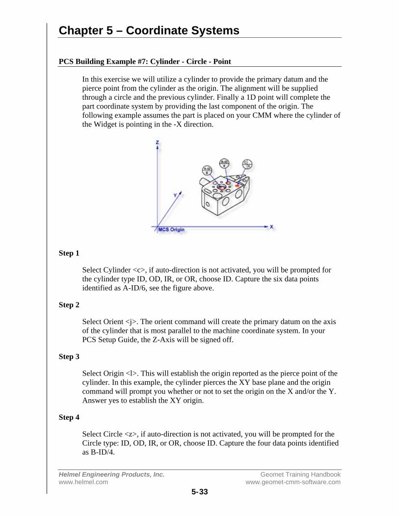
Chapter 5 – Coordinate Systems
Helmel Engineering Products, Inc. Geomet Training Handbookwww.helmel.com www.geomet-cmm-software.com
5-33
PCS Building Example #7: Cylinder - Circle - Point
In this exercise we will utilize a cylinder to provide the primary datum and thepierce point from the cylinder as the origin. The alignment will be suppliedthrough a circle and the previous cylinder. Finally a 1D point will complete thepart coordinate system by providing the last component of the origin. Thefollowing example assumes the part is placed on your CMM where the cylinder ofthe Widget is pointing in the -X direction.
Step 1
Select Cylinder <c>, if auto-direction is not activated, you will be prompted forthe cylinder type ID, OD, IR, or OR, choose ID. Capture the six data pointsidentified as A-ID/6, see the figure above.
Step 2
Select Orient <j>. The orient command will create the primary datum on the axisof the cylinder that is most parallel to the machine coordinate system. In yourPCS Setup Guide, the Z-Axis will be signed off.
Step 3
Select Origin <l>. This will establish the origin reported as the pierce point of thecylinder. In this example, the cylinder pierces the XY base plane and the origincommand will prompt you whether or not to set the origin on the X and/or the Y.Answer yes to establish the XY origin.
Step 4
Select Circle <z>, if auto-direction is not activated, you will be prompted for theCircle type: ID, OD, IR, or OR, choose ID. Capture the four data points identifiedas B-ID/4.
Chapter 5 – Coordinate Systems
Helmel Engineering Products, Inc. Geomet Training Handbookwww.helmel.com www.geomet-cmm-software.com
5-34
Step 5
Select Align <k>. Your ICS will update to include the secondary datum which isderived from the XY circle and the previous XY pierce point from the cylinder.
Step 6
Select -Z Point <2>. The final component missing for your complete PCS is the Zorigin. You will then be prompted to "Measure -Z Point". Capture point C-1.
Step 7
Select Origin <l>. This will solve the Z-axis Origin and complete PCS #1.
Summary
When using a through bore as the primary datum, we must be careful that the datapoint spread is sufficient to allow for a stable feature. In this example we wouldplace an extension on the stylus to allow for a greater reach into the cylinder.
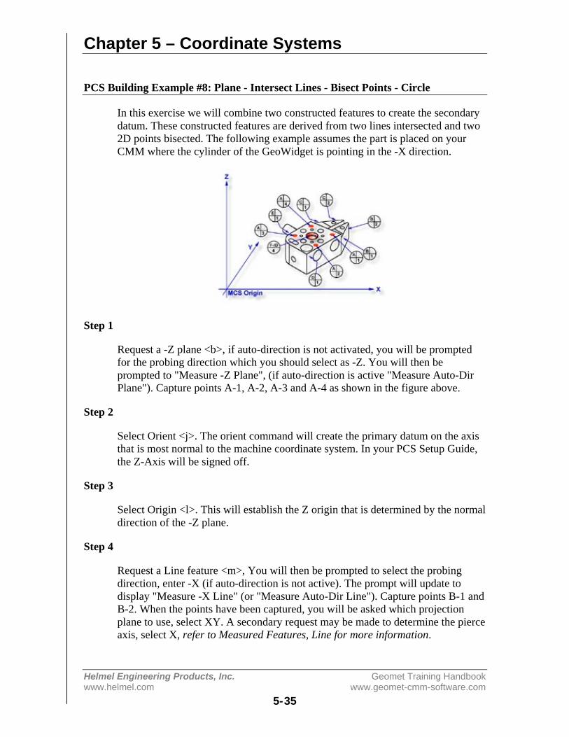
Chapter 5 – Coordinate Systems
Helmel Engineering Products, Inc. Geomet Training Handbookwww.helmel.com www.geomet-cmm-software.com
5-35
PCS Building Example #8: Plane - Intersect Lines - Bisect Points - Circle
In this exercise we will combine two constructed features to create the secondarydatum. These constructed features are derived from two lines intersected and two2D points bisected. The following example assumes the part is placed on yourCMM where the cylinder of the GeoWidget is pointing in the -X direction.
Step 1
Request a -Z plane <b>, if auto-direction is not activated, you will be promptedfor the probing direction which you should select as -Z. You will then beprompted to "Measure -Z Plane", (if auto-direction is active "Measure Auto-DirPlane"). Capture points A-1, A-2, A-3 and A-4 as shown in the figure above.
Step 2
Select Orient <j>. The orient command will create the primary datum on the axisthat is most normal to the machine coordinate system. In your PCS Setup Guide,the Z-Axis will be signed off.
Step 3
Select Origin <l>. This will establish the Z origin that is determined by the normaldirection of the -Z plane.
Step 4
Request a Line feature <m>, You will then be prompted to select the probingdirection, enter -X (if auto-direction is not active). The prompt will update todisplay "Measure -X Line" (or "Measure Auto-Dir Line"). Capture points B-1 andB-2. When the points have been captured, you will be asked which projectionplane to use, select XY. A secondary request may be made to determine the pierceaxis, select X, refer to Measured Features, Line for more information.
Chapter 5 – Coordinate Systems
Helmel Engineering Products, Inc. Geomet Training Handbookwww.helmel.com www.geomet-cmm-software.com
5-36
Step 5
Clear the current mode by pressing the < Esc > key. Request a Line feature <m>,You will then be prompted to select the probing direction, enter +X (if auto-direction is not active). The prompt will update to display "Measure +X Line" (or"Measure Auto-Dir Line"). Capture points C-1 and C-2. When the points havebeen captured, you will be asked which projection plane to use, select XY.
Step 6
Select the Intersect <d> command. This command will take the two projectedlines and solve for the intersection between them. The result will be a 2D XYpoint.
Step 7
Select a 2D XY Point <5> + <2>. The selection of a 2D point requires twocommands. The first command is activated by pressing the < 5 > key, 2D and 3Dpoint selection, which will then prompt which current base plane you will projectinto. After the selection has been completed, Geomet will prompt you to"Measure XY Point". Capture points D-1 and E-1.
Step 8
Select the Bisect <a> command. This command will take the two projected XYpoints and solve for the bisect between them resulting in a 2D XY point.
Step 9
Select in the report display feature number 7 by left clicking on it (2D pointformed by the intersect command). Right-click your mouse and select from thepopup sub menu, <Recall Feature>. This will recall the feature and create newfeature number 11.
Alternatively you can recall a feature by pressing the Recall Feature <h>command from the keyboard. In the control labeled "<- Enter Feature No. toRecall, enter 7 and press the <Ok> button or the <Enter> key on the keyboard.
Step 10
Select Align <k>. Your ICS will update to include the secondary datum which isderived from the recalled 2D XY point and the previous 2D XY point createdfrom the bisect command.

Chapter 5 – Coordinate Systems
Helmel Engineering Products, Inc. Geomet Training Handbookwww.helmel.com www.geomet-cmm-software.com
5-37
Step 11
Select Circle <z>, if auto-direction is not activated, you will be prompted for theCircle type: ID, OD, IR, or OR, choose ID. Capture the four data points identifiedas F-ID/4.
Step 12
Select Origin <l>, the Circle, which is 2D, provides two directions whenestablishing an origin. In our example, the circle can be used for the X and/or theY direction. The origin command will prompt you whether to use the X and thenthe Y. For our example you should answer Yes to both requests. Uponcompletion, you will have established PCS 1.
Summary
In this exercise we had combined features to create constructed features which arethen used to create part coordinate system components. In part production we willfind numerous cases where one or more part coordinate system datums aresymmetry lines or points where no features exist.
When performing constructions in an ICS, it is important to remember theestablished projection base planes that are valid. For example, in this exercise itwould not have produced acceptable results if we established 2 ZX points, oneeach on the top and bottom surfaces of the widget and then perform the bisect.The resulting 2D point would be projected into the alignment of the machinecoordinate system and therefore would not represent a valid point feature for thepart coordinate system.
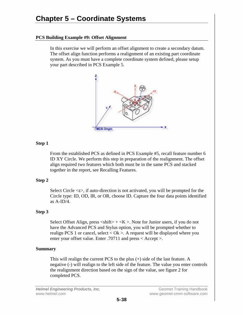
Chapter 5 – Coordinate Systems
Helmel Engineering Products, Inc. Geomet Training Handbookwww.helmel.com www.geomet-cmm-software.com
5-38
PCS Building Example #9: Offset Alignment
In this exercise we will perform an offset alignment to create a secondary datum.The offset align function performs a realignment of an existing part coordinatesystem. As you must have a complete coordinate system defined, please setupyour part described in PCS Example 5.
Step 1
From the established PCS as defined in PCS Example #5, recall feature number 6ID XY Circle. We perform this step in preparation of the realignment. The offsetalign required two features which both must be in the same PCS and stackedtogether in the report, see Recalling Features.
Step 2
Select Circle <z>, if auto-direction is not activated, you will be prompted for theCircle type: ID, OD, IR, or OR, choose ID. Capture the four data points identifiedas A-ID/4.
Step 3
Select Offset Align, press <shift> + <K >. Note for Junior users, if you do nothave the Advanced PCS and Stylus option, you will be prompted whether torealign PCS 1 or cancel, select < Ok >. A request will be displayed where youenter your offset value. Enter .70711 and press < Accept >.
Summary
This will realign the current PCS to the plus (+) side of the last feature. Anegative (-) will realign to the left side of the feature. The value you enter controlsthe realignment direction based on the sign of the value, see figure 2 forcompleted PCS.
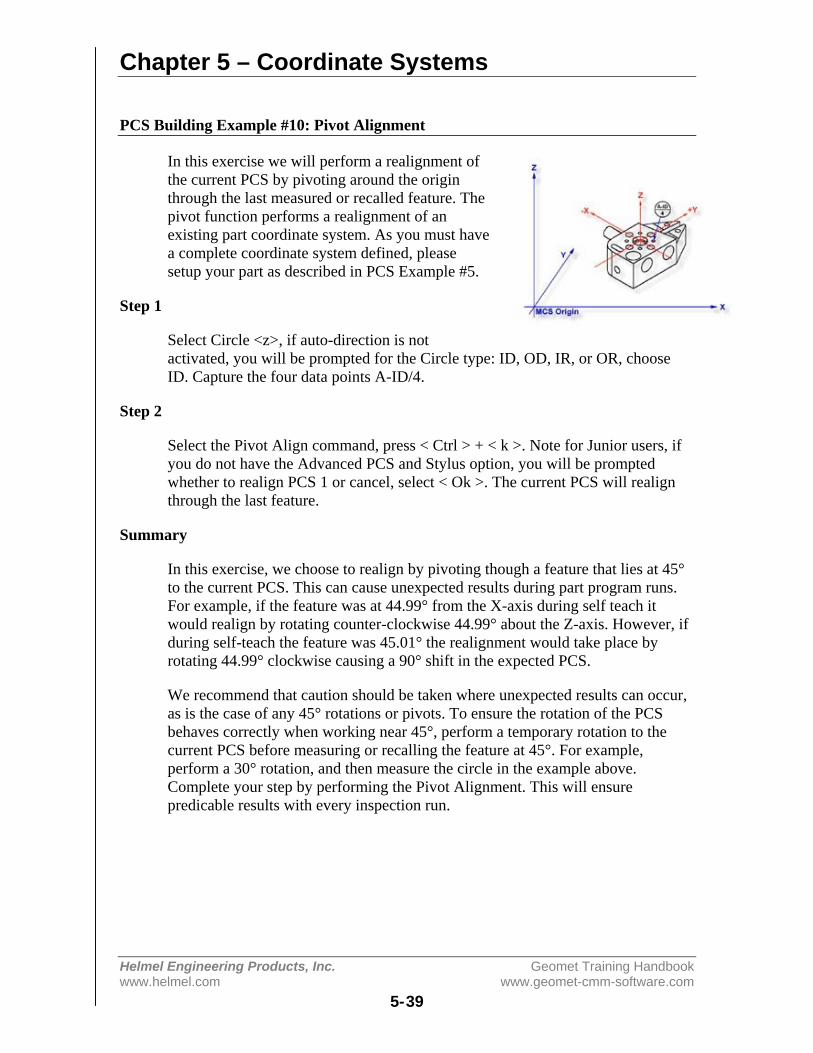
Chapter 5 – Coordinate Systems
Helmel Engineering Products, Inc. Geomet Training Handbookwww.helmel.com www.geomet-cmm-software.com
5-39
PCS Building Example #10: Pivot Alignment
In this exercise we will perform a realignment ofthe current PCS by pivoting around the originthrough the last measured or recalled feature. Thepivot function performs a realignment of anexisting part coordinate system. As you must havea complete coordinate system defined, pleasesetup your part as described in PCS Example #5.
Step 1
Select Circle <z>, if auto-direction is notactivated, you will be prompted for the Circle type: ID, OD, IR, or OR, chooseID. Capture the four data points A-ID/4.
Step 2
Select the Pivot Align command, press < Ctrl > + < k >. Note for Junior users, ifyou do not have the Advanced PCS and Stylus option, you will be promptedwhether to realign PCS 1 or cancel, select < Ok >. The current PCS will realignthrough the last feature.
Summary
In this exercise, we choose to realign by pivoting though a feature that lies at 45°to the current PCS. This can cause unexpected results during part program runs.For example, if the feature was at 44.99° from the X-axis during self teach itwould realign by rotating counter-clockwise 44.99° about the Z-axis. However, ifduring self-teach the feature was 45.01° the realignment would take place byrotating 44.99° clockwise causing a 90° shift in the expected PCS.
We recommend that caution should be taken where unexpected results can occur,as is the case of any 45° rotations or pivots. To ensure the rotation of the PCSbehaves correctly when working near 45°, perform a temporary rotation to thecurrent PCS before measuring or recalling the feature at 45°. For example,perform a 30° rotation, and then measure the circle in the example above.Complete your step by performing the Pivot Alignment. This will ensurepredicable results with every inspection run.
Chapter 5 – Coordinate Systems
Helmel Engineering Products, Inc. Geomet Training Handbookwww.helmel.com www.geomet-cmm-software.com
5-40
PCS Building Example #11: Translate
In this exercise we will take an existing part coordinate system and translate it bynominal amounts in the X and Y-axis. The Translate command can be performedon X, Y and/or Z individually or any combination. As you must have a completecoordinate system defined, please setup your part described in PCS Example #2.
Step 1
Select the Translate command <;>. When you activate this command, Geometwill display a dialog where you can enter your translation values. Enter 2.125 forX and 1.500 for Y and no entry for Z. Press <Accept> to perform the translation.A new PCS will be established, or in the case of Junior, a translation of thecurrent PCS takes place.
Summary
In many conditions, it is required to translate the part coordinate system when youare working with a datum that is derived from points that are not defined on yourpart. For example you may be inspecting a cavity insert which was removed froma progressive die where the datums are a common alignment pin not available atinspection time. Another example is the focal point of an optical lens whosesurface radial may be projected 2,000" from the actual part.
Chapter 5 – Coordinate Systems
Helmel Engineering Products, Inc. Geomet Training Handbookwww.helmel.com www.geomet-cmm-software.com
5-41
PCS Building Example #12: Rotate
In this exercise we will take an existing part coordinate system and rotate it aboutan axis by a nominal value. The rotate command can be perform only about onePCS axis at a time. If you require performing compound rotations, the rotatecommand must be repeated as separate steps. As you must have a completecoordinate system defined, please setup your part described in PCS Exercise 2.
Step 1
Select the Rotate command, press <shift> + < : >. When you select this command,the Rotate PCS Axis dialog will prompt you to enter a nominal value for an axis.Rotations can only be applied to one axis at a time; therefore this rotation tool willensure you enter only one value prior to accepting the nominal value. For thisexercise, enter -5 in the X axis control and press the < Accept > button. A newPCS will be established, or in the case of base Junior, a translation of the currentPCS takes place.
Summary
When we rotated the PCS -5° around the X-axis, our resulting PCS should beparallel to the top surface of the tapered planes located on the taper end of theGeoWidget. To verify that we performed the rotation correct, select a -Z Point<2> feature and probe the top surface of the 5° plane. We should see a -Z pointvalue at .018 ± .005.
Chapter 5 – Coordinate Systems
Helmel Engineering Products, Inc. Geomet Training Handbookwww.helmel.com www.geomet-cmm-software.com
5-42
Coordinate System Manager
The CS Manager provides access to recall established Part Coordinate Systems,Fixture Coordinate Systems, activate the Machine Coordinate System, and ifavailable establish a vector drive coordinate system for manual joystick controlson CMMs with DCC controls.
Recalling a Part Coordinate System
Each time a completed PCS is established, it is given an ascending numberstarting with 1. If you are requesting a PCS recall, activate the Coordinate SystemManager by pressing the key < ' > or through the menu [PCS ⇒ Recall PCS].When the CS Manager appears ensure that the PCS button is pressed in the SelectType group. Any existing PCS can then be made the current PCS by entering thedesired PCS number. Optionally you can utilize the slider control next to the"Select Type" group to scroll through the available PCSs. If you were to enter a 0for the desired PCS, you are in effect recalling the machine coordinate system.Press the <Ok> button to complete the recall function.
Recalling the Machine Coordinate System
Recalling the Machine Coordinate System can be accomplished by activating theCoordinate System Manager as described above and ensure that the MCS buttonis pressed in the Select Type group. Press the <Ok> button to complete the recallfunction.
Recalling a Fixture Coordinate System
To request an FCS recall, activate the Coordinate System Manager by pressingthe key < ' > and ensure that the FCS button is pressed in the Select Type group.Any existing FCS can then be recalled and made the current PCS by entering thedesired FCS number. Optionally you can utilize the slider control next to the"Select Type" group to scroll through the available FCSs. Press the <Ok> buttonto complete the recall function.
Chapter 5 – Coordinate Systems
Helmel Engineering Products, Inc. Geomet Training Handbookwww.helmel.com www.geomet-cmm-software.com
5-43
Recalling a Vector Drive System
The recalling of a Vector Drive is available only on CMMs that have DCCcontrol. Normally, the joystick deflections in X, Y and Z move parallel to theMachine Coordinate System. Vector Drive, when activated, moves parallel to aspecified Part Coordinate System.
To request a Vector Drive CS, activate the Coordinate System Manager bypressing the key < ' > and ensure that the Vector button is pressed in the SelectType group. The current range of numbered Part Coordinate Systems will bedisplayed from which you can select the current Vector Drive CS. Optionally, youcan utilize the slider control next to the "Select Type" group to scroll through theavailable PCSs. Press the <Ok> button to complete the recall function.
Any existing Part Coordinate System geometry can be recalled and made thecurrent Vector Drive CS, even if it is not the current PCS in your inspection setup.This allows you to manually drive the CMM in one PCS, and measure in another.This is helpful when motion is required to follow small details such as entering asmall slot that is not in line with the current PCS.
When you recall a Vector Drive CS, it is not recorded as a step in your partinspection. The Vector Drive CS remains active until you select another VectorDrive CS. Should you want to remove the current Vector Drive CS and return tonormal operations, select the MCS, or 0, in the Vector Drive CS recall procedure.

Chapter 5 – Coordinate Systems
Helmel Engineering Products, Inc. Geomet Training Handbookwww.helmel.com www.geomet-cmm-software.com
5-44
Fixture Coordinate System Manager
A Fixture Coordinate System (FCS) is a previously defined coordinate systemsaved in a separate database available to all inspection programs for inclusion as aPCS. The use of a FCS allows a repeatable location in the CMM measuring cubewhere inspections take place. An example would be a cradle fixture that holds aproduction part in one orientation and fixed location.
The use of a FCS requires that the CMM have a known home position, which iscommon on all DCC CMMs and on few manual CMMs.
The process of creating a FCS entails establishing a PCS on the fixture and thenactivating the FCS Manager to append to the database the specific geometry thatdefines the FCS. Using a FCS requires recalling the FCS by the assigned numberthrough the Coordinate System Manager.
The FCS Manager also provides tools to create a program step within aninspection program where the verification and update of existing FCSs can bedone programmatically. This provides the operator a means to rebuild existingFCSs through the execution of a part program.
The FCS Manager is activated by:
Keyboard: shift + L
Menu: PCS ⇒ FCS Manager

Chapter 5 – Coordinate Systems
Helmel Engineering Products, Inc. Geomet Training Handbookwww.helmel.com www.geomet-cmm-software.com
5-45
IMPORTANT! Importing Previous FCS Definitions
With the release of Geomet version 6.66 in December 2005, Geomet no longerutilizes the Windows Registry to save the data for Fixture Coordinate Systems.Geomet now utilizes a separate data file with a default name of “Geomet.gcs”which is located in the Geomet program folder where “Geomet.exe” has beeninstalled.
This change was made to allow greater flexibility for the future development andto overcome limitation with multi-user operating systems such as Windows XP.In a multi-user system, each operator has his or her own Windows Registry. In thecase of FCSs, if Operator-A created a FCS, it was not available to Operator-B.
To overcome this, Geomet provides an automatic one-time Import and Convertprocess to extract all FCS data from the Windows Registry and build the new FCSdatabase file. This process activates when one of the following actions occur:
• Activating the Fixture Coordinate Manager.• Editing the FCS to PCS Inspection Step.• Using the PCS Recall Manager.• Running an Inspection Program with a FCS Inspection step.
It is recommended that when you run Geomet version 6.66 for the first time,launch the FCS Manager and the Import and Convert function will process yourFCSs into the new database. This will occur only once.
Performing the Import and Convert
Upon launching the FCS Manager, Geomet will test the Windows Registry ifthere are any FCS definition data. Should FCS data be found, you will beprompted to import the data.
The recommended response is <Yes>. Upon selecting <Yes> Geomet will importall FCS data into the database and delete all entries in the Windows Registry. TheFCS Manager will be launched and your FCS data will be displayed.
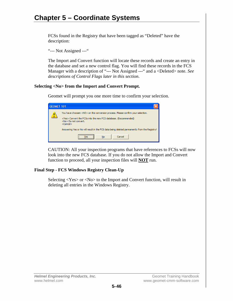
Chapter 5 – Coordinate Systems
Helmel Engineering Products, Inc. Geomet Training Handbookwww.helmel.com www.geomet-cmm-software.com
5-46
FCSs found in the Registry that have been tagged as “Deleted” have thedescription:
“--- Not Assigned ---“
The Import and Convert function will locate these records and create an entry inthe database and set a new control flag. You will find these records in the FCSManager with a description of “--- Not Assigned ---“ and a <Deleted> note. Seedescriptions of Control Flags later in this section.
Selecting <No> from the Import and Convert Prompt.
Geomet will prompt you one more time to confirm your selection.
CAUTION: All your inspection programs that have references to FCSs will nowlook into the new FCS database. If you do not allow the Import and Convertfunction to proceed, all your inspection files will NOT run.
Final Step - FCS Windows Registry Clean-Up
Selecting <Yes> or <No> to the Import and Convert function, will result indeleting all entries in the Windows Registry.
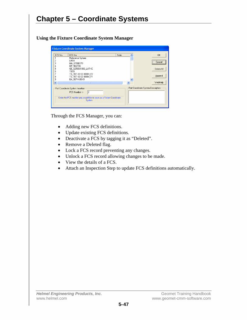
Chapter 5 – Coordinate Systems
Helmel Engineering Products, Inc. Geomet Training Handbookwww.helmel.com www.geomet-cmm-software.com
5-47
Using the Fixture Coordinate System Manager
Through the FCS Manager, you can:
• Adding new FCS definitions.• Update existing FCS definitions.• Deactivate a FCS by tagging it as “Deleted”.• Remove a Deleted flag.• Lock a FCS record preventing any changes.• Unlock a FCS record allowing changes to be made.• View the details of a FCS.• Attach an Inspection Step to update FCS definitions automatically.
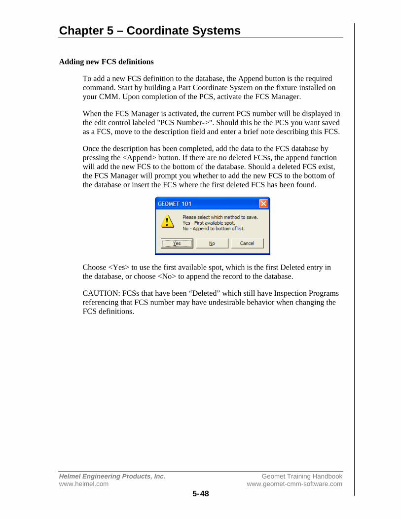
Chapter 5 – Coordinate Systems
Helmel Engineering Products, Inc. Geomet Training Handbookwww.helmel.com www.geomet-cmm-software.com
5-48
Adding new FCS definitions
To add a new FCS definition to the database, the Append button is the requiredcommand. Start by building a Part Coordinate System on the fixture installed onyour CMM. Upon completion of the PCS, activate the FCS Manager.
When the FCS Manager is activated, the current PCS number will be displayed inthe edit control labeled "PCS Number->". Should this be the PCS you want savedas a FCS, move to the description field and enter a brief note describing this FCS.
Once the description has been completed, add the data to the FCS database bypressing the <Append> button. If there are no deleted FCSs, the append functionwill add the new FCS to the bottom of the database. Should a deleted FCS exist,the FCS Manager will prompt you whether to add the new FCS to the bottom ofthe database or insert the FCS where the first deleted FCS has been found.
Choose <Yes> to use the first available spot, which is the first Deleted entry inthe database, or choose <No> to append the record to the database.
CAUTION: FCSs that have been “Deleted” which still have Inspection Programsreferencing that FCS number may have undesirable behavior when changing theFCS definitions.
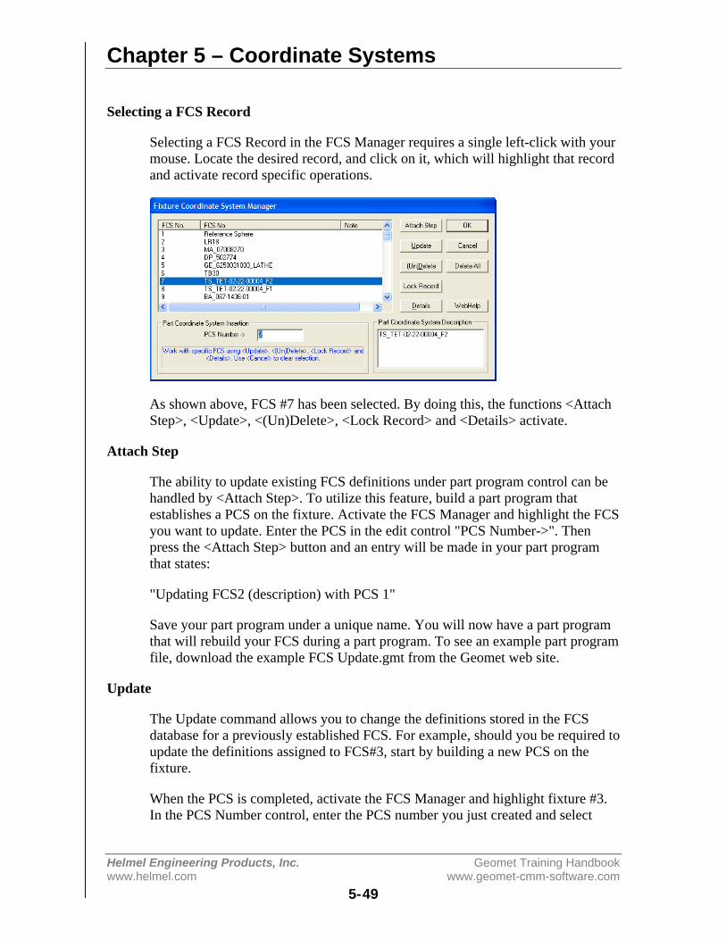
Chapter 5 – Coordinate Systems
Helmel Engineering Products, Inc. Geomet Training Handbookwww.helmel.com www.geomet-cmm-software.com
5-49
Selecting a FCS Record
Selecting a FCS Record in the FCS Manager requires a single left-click with yourmouse. Locate the desired record, and click on it, which will highlight that recordand activate record specific operations.
As shown above, FCS #7 has been selected. By doing this, the functions <AttachStep>, <Update>, <(Un)Delete>, <Lock Record> and <Details> activate.
Attach Step
The ability to update existing FCS definitions under part program control can behandled by <Attach Step>. To utilize this feature, build a part program thatestablishes a PCS on the fixture. Activate the FCS Manager and highlight the FCSyou want to update. Enter the PCS in the edit control "PCS Number->". Thenpress the <Attach Step> button and an entry will be made in your part programthat states:
"Updating FCS2 (description) with PCS 1"
Save your part program under a unique name. You will now have a part programthat will rebuild your FCS during a part program. To see an example part programfile, download the example FCS Update.gmt from the Geomet web site.
Update
The Update command allows you to change the definitions stored in the FCSdatabase for a previously established FCS. For example, should you be required toupdate the definitions assigned to FCS#3, start by building a new PCS on thefixture.
When the PCS is completed, activate the FCS Manager and highlight fixture #3.In the PCS Number control, enter the PCS number you just created and select

Chapter 5 – Coordinate Systems
Helmel Engineering Products, Inc. Geomet Training Handbookwww.helmel.com www.geomet-cmm-software.com
5-50
<Update>. FCS #3 will be updated with the latest coordinate system data from thePCS.
Delete / Un-Delete
To delete a FCS from being available in the database, highlight the FCS and clickon <(Un) Delete>. The FCS number will remain in the list and control flag will beset to Delete. Under the Note column, the FCS Manager will display <Deleted>.All part programs that reference this FCS will prompt with a warning about amissing FCS when it is opened.
The Delete command does not remove the FCS definitions from the database onlymakes them unavailable. The Delete command can also remove the delete flagmaking it available again.
If a FCS has been “Locked”, the Delete command will not be allowed.
Lock Record
The ability to Lock a FCS is new to Geomet version 6.66. Locking a recordprevents changes from being made. These include Deleting and Updating. Toattach a Lock, locate the FCS in the FCS Manager and select it. Press the <LockRecord> button and the record will be locked. Under the Note column, you willsee the entry <Locked>.
NOTE: You can not apply a Lock to a record that has been deleted.
Details
To view the definitions of a selected FCS, highlight the FCS in the list and select<Details>. The data shown is the XYZ axis vectors followed by the MCS origin.The information provided by Details can be helpful in locating the origin and thedirectional vectors for each FCS axis. You should have a complete knowledge ofcoordinate system components in order to fully understand the values shown.
Delete All
The <Delete All> button clears out the entire FCS database.
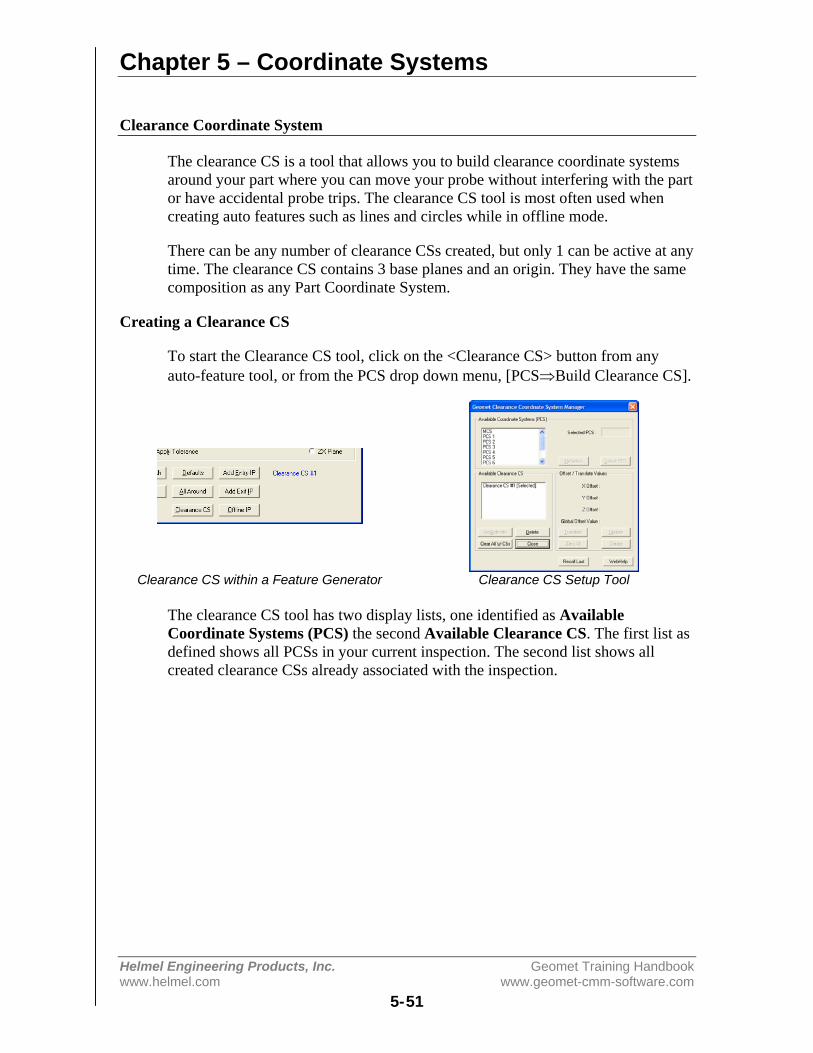
Chapter 5 – Coordinate Systems
Helmel Engineering Products, Inc. Geomet Training Handbookwww.helmel.com www.geomet-cmm-software.com
5-51
Clearance Coordinate System
The clearance CS is a tool that allows you to build clearance coordinate systemsaround your part where you can move your probe without interfering with the partor have accidental probe trips. The clearance CS tool is most often used whencreating auto features such as lines and circles while in offline mode.
There can be any number of clearance CSs created, but only 1 can be active at anytime. The clearance CS contains 3 base planes and an origin. They have the samecomposition as any Part Coordinate System.
Creating a Clearance CS
To start the Clearance CS tool, click on the <Clearance CS> button from anyauto-feature tool, or from the PCS drop down menu, [PCS⇒Build Clearance CS].
Clearance CS within a Feature Generator Clearance CS Setup Tool
The clearance CS tool has two display lists, one identified as AvailableCoordinate Systems (PCS) the second Available Clearance CS. The first list asdefined shows all PCSs in your current inspection. The second list shows allcreated clearance CSs already associated with the inspection.

Chapter 5 – Coordinate Systems
Helmel Engineering Products, Inc. Geomet Training Handbookwww.helmel.com www.geomet-cmm-software.com
5-52
Selecting a PCS Clearance CS to PCS Relationship
To create a Clearance CS, start by highlighting a PCS in the available list, seefigure above where PCS #1 is highlighted. Click the <Select PCS> button ordouble click on the PCS name in the list. Control will pass to the "Offset /Translate Values" group allowing you to enter XYZ offset values. These valuesshould be carefully understood, as they will directly affect the motion of yoursystem. The 1-2-3 block example in the figure above right, shows that the partcoordinate system is established on the top surface and lower left corner.
We will enter offset values of:
X Offset: -0.500Y Offset: 2.500Z Offset: 0.500
After entering the values, press the <Create> button and a new Clearance CS willappear in the list with the next available number. As shown in figure above, theClearance CS has its origin outside the part creating three planes that will allowmotion within those planes that will not intrude into the part.
You can create as many Clearance CSs that are required to provide zone transitionplanes around your part and any fixtures being used.
Chapter 5 – Coordinate Systems
Helmel Engineering Products, Inc. Geomet Training Handbookwww.helmel.com www.geomet-cmm-software.com
5-53
Translate an Existing Clearance CS
Translate allows you to quickly take an existing Clearance CS and create a newClearance CS based on XYZ Offset values. To illustrate, we will take clearanceCS #1 and create a second clearance CS 3.000" in the –Y direction. Start byhighlighting the name "Clearance CS #1", the current values will display in theOffset / Translate Group. Edit the XYZ translation values to:
X Offset: -0.000Y Offset: -3.000Z Offset: 0.000
Press the <Translate> button and a new clearance CS is created and entered intothe available list.
Update an Existing Clearance CS
This feature allows you to update the current offset values for an existingclearance CS. In some cases it may be required to extend an offset for bettermotion path generation. To update an existing clearance CS, highlight thatClearance CS in the list and when the current entered values are displayed in theOffset / Translate Group, you can then edit them. Make the changes to theclearance CS by pressing The <Update> button.
NOTE: Any feature that currently uses the Clearance CS being updated will haveall motion relating to the Clearance CS updated automatically.
Deleting a Clearance CS
Deleting a clearance CS will remove all references to the clearance planes definedin the selected clearance CS. To delete, highlight the name in the AvailableClearance Plane CS list. Click on the button <Delete> and it will be removedpermanently from the inspection program.
NOTE: Any features that refer to the deleted clearance CS must be reviewed andcorrected manually.

Chapter 5 – Coordinate Systems
Helmel Engineering Products, Inc. Geomet Training Handbookwww.helmel.com www.geomet-cmm-software.com
5-54
Clear All Existing Clearance CSs
This feature will remove all clearance CSs from you part program. Caution shouldbe taken when using this feature. If your part program has any Auto-IPs, they willlose reference to the Clearance CS and motion behavior can be greatly affected.
NOTE: Unlike Part Coordinate Systems, clearance CSs contain relative offsetvalues based on a recalculated PCS. Every time a part inspection is performed,any PCSs are rebuilt based on current features. Clearance CS is then build againstthe assigned PCS and therefore it is considered dynamic during the partinspection.
Activating a Clearance CS
Activating a clearance CS will allow all other editing tools to use the clearanceplanes defined in the Clearance CS. To set it active, highlight the name in theAvailable Clearance Plane CS list. Click on the button <(de)Activate> to changeits status.
Chapter 6 – Tolerance
Helmel Engineering Products, Inc. Geomet Training Handbookwww.helmel.com www.geomet-cmm-software.com
6-1
Chapter 6 – Tolerance
Introduction to Tolerance................................................................... 6-2
Linear Tolerance Theory.................................................................... 6-3
Working with Geomet Tolerance Windows ...................................... 6-5
Working with True Position Tolerance Windows ............................. 6-7
Interpreting Linear Tolerance in Geomet .......................................... 6-8
True Position Tolerance Theory ........................................................ 6-9
Datum Bonus Tolerance .................................................................. 6-11
Process Control Tolerance ............................................................... 6-12
Out-of-Tolerance Flash Message..................................................... 6-15
Vector Point Features – Apply Tolerance using Profile Bands ....... 6-16
GeoTol – Form Tolerance................................................................ 6-17
Runout: Cylinder/Plane.................................................................... 6-18

Chapter 6 – Tolerance
Helmel Engineering Products, Inc. Geomet Training Handbookwww.helmel.com www.geomet-cmm-software.com
6-2
Introduction to Tolerance
Before we discuss how Geomet applies tolerance to a feature, it is useful toreview the various reporting formats available. These formats include Linear orTrue Position tolerance reported in either Cartesian or Polar formats. All featurelocations are reported against a Datum Frame Reference or PCS (Part CoordinateSystem). A two-dimension feature will report its location in one PCS base plane.An example would be an XY Point consisting of an X-axis, a Y-axis and anorigin, see example below.
The example above illustrates how the location of a point Pt1, (example would bea center of a bore) can be expressed in either Cartesian (X, Y) or Polar (r, AX/Y)coordinates. In the Cartesian format the coordinates X and Y are the distancesbetween Pt1 and the origin as measured along the X and Y-axis respectively. Inthe Polar format, r represents the straight-line distance between Pt1 and theorigin, and AX/Y represents the angle that the radius line makes with the X-axis.
Geomet defaults to Cartesian format, which can be changed in the SystemOptions. To change the reporting format during the teaching of a part inspection,press the <e> (Cart/Pol) key on the keyboard. To change the reporting format of asingle feature, highlight the feature and activate the sub menu with a right click.Choose either Cartesian or Polar from the Feature Characteristics command.
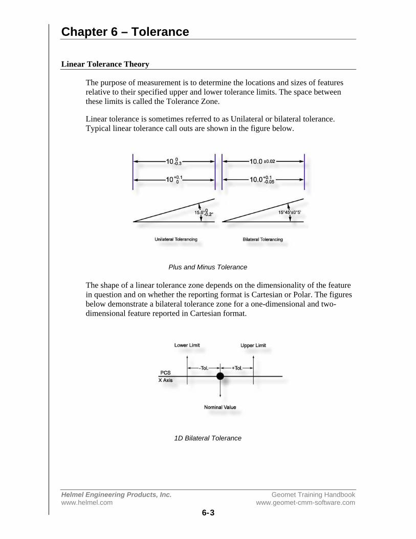
Chapter 6 – Tolerance
Helmel Engineering Products, Inc. Geomet Training Handbookwww.helmel.com www.geomet-cmm-software.com
6-3
Linear Tolerance Theory
The purpose of measurement is to determine the locations and sizes of featuresrelative to their specified upper and lower tolerance limits. The space betweenthese limits is called the Tolerance Zone.
Linear tolerance is sometimes referred to as Unilateral or bilateral tolerance.Typical linear tolerance call outs are shown in the figure below.
Plus and Minus Tolerance
The shape of a linear tolerance zone depends on the dimensionality of the featurein question and on whether the reporting format is Cartesian or Polar. The figuresbelow demonstrate a bilateral tolerance zone for a one-dimensional and two-dimensional feature reported in Cartesian format.
1D Bilateral Tolerance
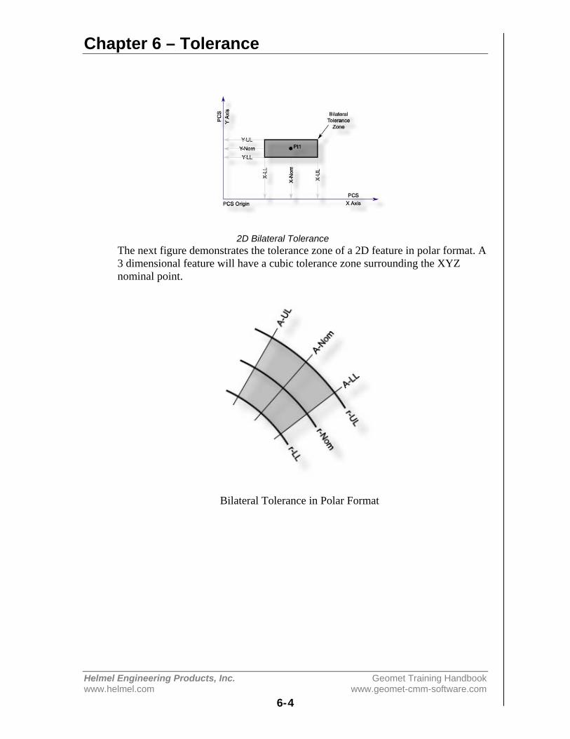
Chapter 6 – Tolerance
Helmel Engineering Products, Inc. Geomet Training Handbookwww.helmel.com www.geomet-cmm-software.com
6-4
2D Bilateral ToleranceThe next figure demonstrates the tolerance zone of a 2D feature in polar format. A3 dimensional feature will have a cubic tolerance zone surrounding the XYZnominal point.
Bilateral Tolerance in Polar Format
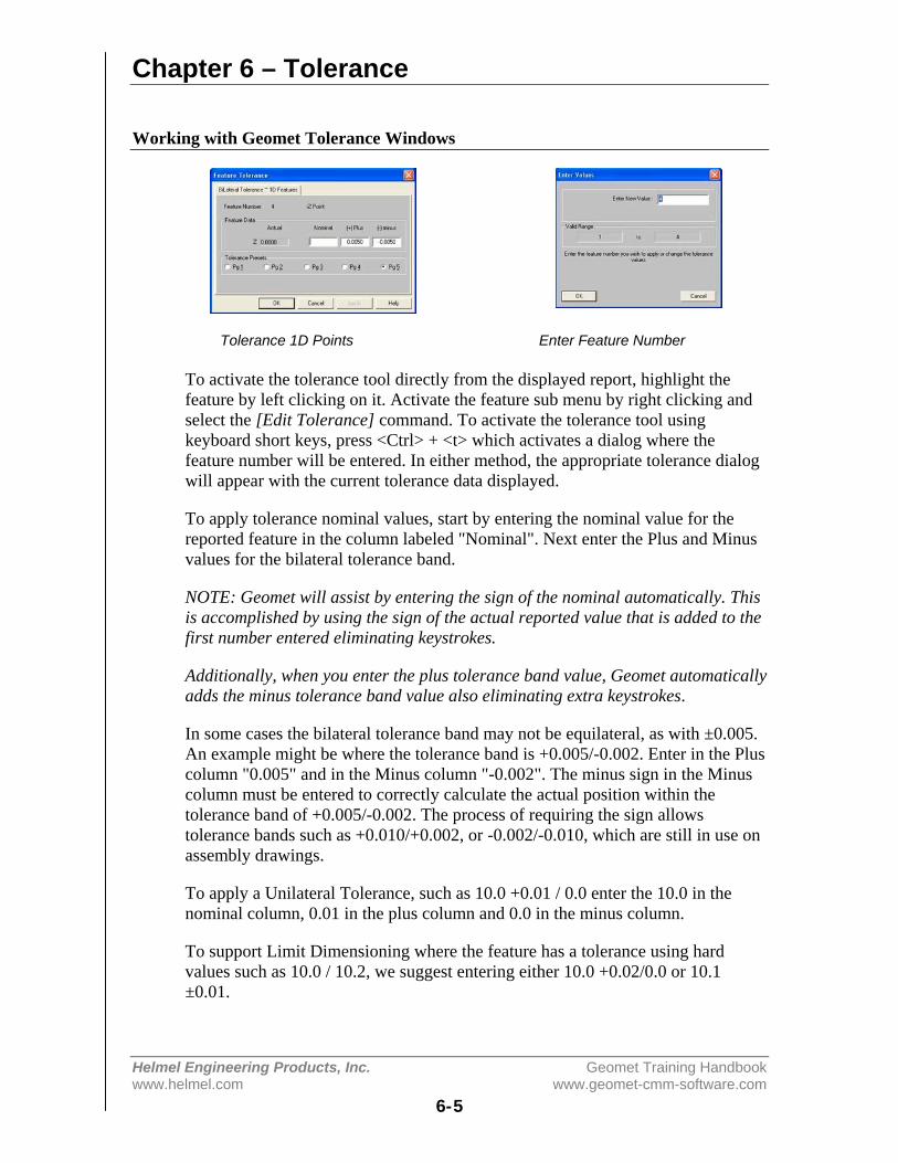
Chapter 6 – Tolerance
Helmel Engineering Products, Inc. Geomet Training Handbookwww.helmel.com www.geomet-cmm-software.com
6-5
Working with Geomet Tolerance Windows
Tolerance 1D Points Enter Feature Number
To activate the tolerance tool directly from the displayed report, highlight thefeature by left clicking on it. Activate the feature sub menu by right clicking andselect the [Edit Tolerance] command. To activate the tolerance tool usingkeyboard short keys, press <Ctrl> + <t> which activates a dialog where thefeature number will be entered. In either method, the appropriate tolerance dialogwill appear with the current tolerance data displayed.
To apply tolerance nominal values, start by entering the nominal value for thereported feature in the column labeled "Nominal". Next enter the Plus and Minusvalues for the bilateral tolerance band.
NOTE: Geomet will assist by entering the sign of the nominal automatically. Thisis accomplished by using the sign of the actual reported value that is added to thefirst number entered eliminating keystrokes.
Additionally, when you enter the plus tolerance band value, Geomet automaticallyadds the minus tolerance band value also eliminating extra keystrokes.
In some cases the bilateral tolerance band may not be equilateral, as with ±0.005.An example might be where the tolerance band is +0.005/-0.002. Enter in the Pluscolumn "0.005" and in the Minus column "-0.002". The minus sign in the Minuscolumn must be entered to correctly calculate the actual position within thetolerance band of +0.005/-0.002. The process of requiring the sign allowstolerance bands such as +0.010/+0.002, or -0.002/-0.010, which are still in use onassembly drawings.
To apply a Unilateral Tolerance, such as 10.0 +0.01 / 0.0 enter the 10.0 in thenominal column, 0.01 in the plus column and 0.0 in the minus column.
To support Limit Dimensioning where the feature has a tolerance using hardvalues such as 10.0 / 10.2, we suggest entering either 10.0 +0.02/0.0 or 10.1±0.01.

Chapter 6 – Tolerance
Helmel Engineering Products, Inc. Geomet Training Handbookwww.helmel.com www.geomet-cmm-software.com
6-6
On every tolerance dialog, there exists radio buttons to assign a Tolerance Preset.It would only be required that the nominal value be entered followed by theselection of a tolerance preset. For further explanation on tolerance presets, pleaserefer to System Options. To assign a tolerance preset, press the <Alt> + <2> keycombination to assign tolerance preset #2 or left click with the mouse on theselection.
Not all data fields are required to contain data. If you are required only totolerance the X value on a XY Point feature, enter the X nominal and leave the Ynominal blank. Geomet will then report only the tolerance data on the X-axisvalues.
TIP: It is more efficient to move between edit controls using the tab key or the upand down arrow keys on the keyboard. The order of movement on the tolerancedialog utilizing the tab key is Nominal⇒Plus⇒Minus with each press of the<tab> key. Should you want to reverse that order, press <Shift> + <tab>. The<Enter> key at any time solves the application of the tolerance data and closesthe tolerance tool. To navigate only between the edit controls in the Nominalcolumn, use the up and down arrow keys. It is not necessary to locate the mouse,which in this case, makes the tolerance tool very inefficient.
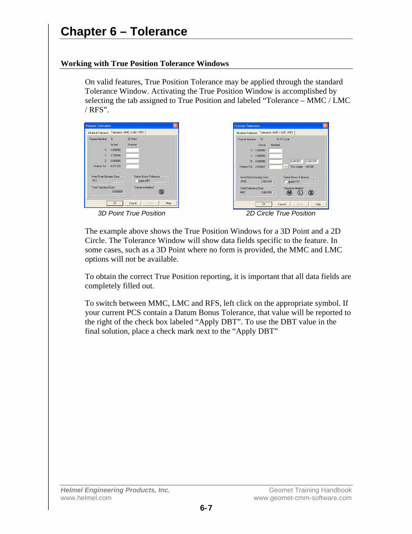
Chapter 6 – Tolerance
Helmel Engineering Products, Inc. Geomet Training Handbookwww.helmel.com www.geomet-cmm-software.com
6-7
Working with True Position Tolerance Windows
On valid features, True Position Tolerance may be applied through the standardTolerance Window. Activating the True Position Window is accomplished byselecting the tab assigned to True Position and labeled “Tolerance – MMC / LMC/ RFS”.
3D Point True Position 2D Circle True Position
The example above shows the True Position Windows for a 3D Point and a 2DCircle. The Tolerance Window will show data fields specific to the feature. Insome cases, such as a 3D Point where no form is provided, the MMC and LMCoptions will not be available.
To obtain the correct True Position reporting, it is important that all data fields arecompletely filled out.
To switch between MMC, LMC and RFS, left click on the appropriate symbol. Ifyour current PCS contain a Datum Bonus Tolerance, that value will be reported tothe right of the check box labeled “Apply DBT”. To use the DBT value in thefinal solution, place a check mark next to the “Apply DBT”
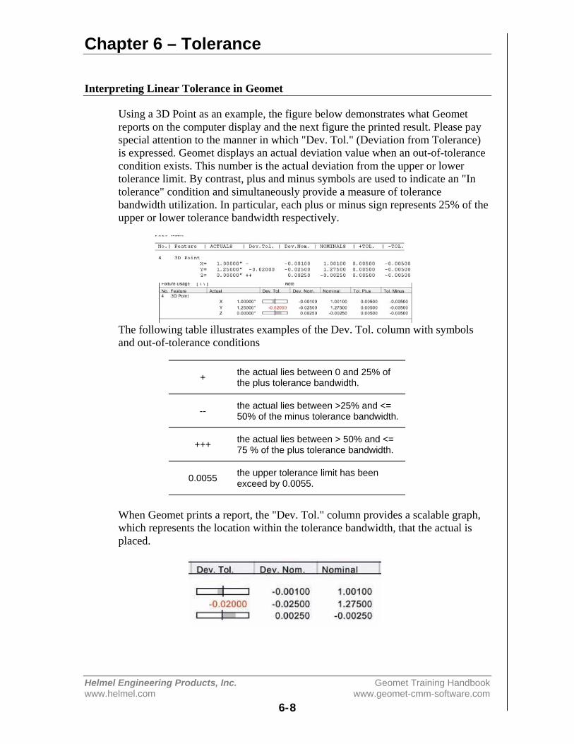
Chapter 6 – Tolerance
Helmel Engineering Products, Inc. Geomet Training Handbookwww.helmel.com www.geomet-cmm-software.com
6-8
Interpreting Linear Tolerance in Geomet
Using a 3D Point as an example, the figure below demonstrates what Geometreports on the computer display and the next figure the printed result. Please payspecial attention to the manner in which "Dev. Tol." (Deviation from Tolerance)is expressed. Geomet displays an actual deviation value when an out-of-tolerancecondition exists. This number is the actual deviation from the upper or lowertolerance limit. By contrast, plus and minus symbols are used to indicate an "Intolerance" condition and simultaneously provide a measure of tolerancebandwidth utilization. In particular, each plus or minus sign represents 25% of theupper or lower tolerance bandwidth respectively.
The following table illustrates examples of the Dev. Tol. column with symbolsand out-of-tolerance conditions
+ the actual lies between 0 and 25% ofthe plus tolerance bandwidth.
-- the actual lies between >25% and <=50% of the minus tolerance bandwidth.
+++ the actual lies between > 50% and <=75 % of the plus tolerance bandwidth.
0.0055 the upper tolerance limit has beenexceed by 0.0055.
When Geomet prints a report, the "Dev. Tol." column provides a scalable graph,which represents the location within the tolerance bandwidth, that the actual isplaced.
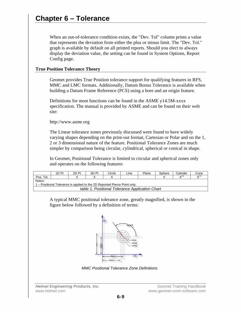
Chapter 6 – Tolerance
Helmel Engineering Products, Inc. Geomet Training Handbookwww.helmel.com www.geomet-cmm-software.com
6-9
When an out-of-tolerance condition exists, the "Dev. Tol" column prints a valuethat represents the deviation from either the plus or minus limit. The "Dev. Tol."graph is available by default on all printed reports. Should you elect to alwaysdisplay the deviation value, the setting can be found in System Options, ReportConfig page.
True Position Tolerance Theory
Geomet provides True Position tolerance support for qualifying features in RFS,MMC and LMC formats. Additionally, Datum Bonus Tolerance is available whenbuilding a Datum Frame Reference (PCS) using a bore and an origin feature.
Definitions for most functions can be found in the ASME y14.5M-xxxxspecification. The manual is provided by ASME and can be found on their website:
http://www.asme.org
The Linear tolerance zones previously discussed were found to have widelyvarying shapes depending on the print-out format, Cartesian or Polar and on the 1,2 or 3 dimensional nature of the feature. Positional Tolerance Zones are muchsimpler by comparison being circular, cylindrical, spherical or conical in shape.
In Geomet, Positional Tolerance is limited to circular and spherical zones onlyand operates on the following features:
1D Pt 2D Pt 3D Pt Circle Line Plane Sphere Cylinder ConePos. Tol. X X X X X(1) X(1)
Notes:1 – Positional Tolerance is applied to the 2D Reported Pierce Point only.
table 1, Positional Tolerance Application Chart
A typical MMC positional tolerance zone, greatly magnified, is shown in thefigure below followed by a definition of terms:
MMC Positional Tolerance Zone Definitions
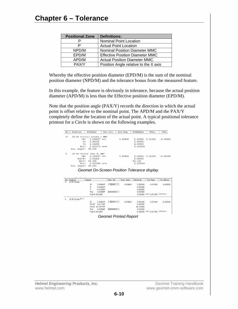
Chapter 6 – Tolerance
Helmel Engineering Products, Inc. Geomet Training Handbookwww.helmel.com www.geomet-cmm-software.com
6-10
Positional Zone Definitions:P Nominal Point LocationP’ Actual Point Location
NPD/M Nominal Position Diameter MMCEPD/M Effective Position Diameter MMCAPD/M Actual Position Diameter MMCPAX/Y Position Angle relative to the X axis
Whereby the effective position diameter (EPD/M) is the sum of the nominalposition diameter (NPD/M) and the tolerance bonus from the measured feature.
In this example, the feature is obviously in tolerance, because the actual positiondiameter (APD/M) is less than the Effective position diameter (EPD/M).
Note that the position angle (PAX/Y) records the direction in which the actualpoint is offset relative to the nominal point. The APD/M and the PAX/Ycompletely define the location of the actual point. A typical positional toleranceprintout for a Circle is shown on the following examples.
Geomet On-Screen Position Tolerance display
Geomet Printed Report
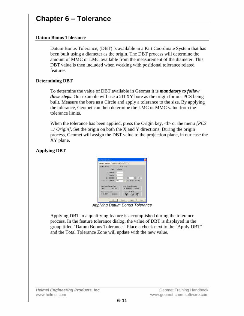
Chapter 6 – Tolerance
Helmel Engineering Products, Inc. Geomet Training Handbookwww.helmel.com www.geomet-cmm-software.com
6-11
Datum Bonus Tolerance
Datum Bonus Tolerance, (DBT) is available in a Part Coordinate System that hasbeen built using a diameter as the origin. The DBT process will determine theamount of MMC or LMC available from the measurement of the diameter. ThisDBT value is then included when working with positional tolerance relatedfeatures.
Determining DBT
To determine the value of DBT available in Geomet it is mandatory to followthese steps. Our example will use a 2D XY bore as the origin for our PCS beingbuilt. Measure the bore as a Circle and apply a tolerance to the size. By applyingthe tolerance, Geomet can then determine the LMC or MMC value from thetolerance limits.
When the tolerance has been applied, press the Origin key, <l> or the menu [PCS⇒ Origin]. Set the origin on both the X and Y directions. During the originprocess, Geomet will assign the DBT value to the projection plane, in our case theXY plane.
Applying DBT
Applying Datum Bonus Tolerance
Applying DBT to a qualifying feature is accomplished during the toleranceprocess. In the feature tolerance dialog, the value of DBT is displayed in thegroup titled "Datum Bonus Tolerance". Place a check next to the "Apply DBT"and the Total Tolerance Zone will update with the new value.

Chapter 6 – Tolerance
Helmel Engineering Products, Inc. Geomet Training Handbookwww.helmel.com www.geomet-cmm-software.com
6-12
Process Control Tolerance
As the name implies, Process Control Tolerance (PCT) is a form of controllingthe manufacturing process by monitoring production and automatically reportingconditions that require correction to the process before non-compliance issuesarise. Traditionally a feature attribute has a single tolerance value that, whenexceeded, was reported only as non-conforming. By the time a non-conformancehad been identified, the manufacturing process may have produced parts that maynow require expensive repairs.
Using PCT allows the inspector to establish differentbut simultaneous tolerance zones for position and sizeof features. For example the size of a bore might bespecified as 1.000 +/- .001. Under PCT controls thecontrols values might look like:
Nominal [Zone A] / [Zone B] / [Zone C] / [Zone D]
- or - 1.000 [+/-.0007] / [+/-.0008] / [+/-.0009] / [+/-.001]
As shown in figure – PCT Tolerance Zones, We break down the tolerance bandinto zones of control. Each zone is identified by Geomet as Zone A / Zone B /Zone C and Zone D.
PCT Tolerance Zone Suggested Descriptions
Zone A - action trigger levelThis portion of the tolerance zone is considered in compliance and requires noaction. The default value for this zone is 70% of the allowable tolerance, but maybe changed to any desirable percent of tolerance.
Zone BZone B is the portion of the tolerance zone that exceeds the limit established byZone A. It is monitored as a first response to provide corrective action to bring theproduction process back under the trigger limit. Production is still withintolerance limits. The default limit of this zone is 70% - 80% of the allowabletolerance zone.
Zone CThis portion of the tolerance zone requires immediate action to correct a potentialproduction problem. The production is still within the tolerance limit, but beyonda trigger zone that requires immediate attention. The default limit for this value is80% - 90% of the allowable tolerance zone.
PCT Tolerance Zones

Chapter 6 – Tolerance
Helmel Engineering Products, Inc. Geomet Training Handbookwww.helmel.com www.geomet-cmm-software.com
6-13
Zone DThis level equals 90% of the allowable tolerance zone and identifies theproduction as non-conforming that requires a material review.
Zone Suggested ActionABCD
No action required.Notify Manufacturing and monitor.Notify Manufacturing and review process.Notify Management and adjust process.
Applying Process Control Tolerance
You access the PCT dialog when you apply standard tolerance from withinGeomet. In our example, the feature being toleranced is a standard 2D circle. Thetolerance box will have a buttons next to all Actual values. The “<<” is the accessbutton to start the PCT Dialog.
Feature Tolerance Dialog PCT Dialog
Process Control Tolerance Application Dialog
Each zone can be edited with a custom value or the <Use Default> button can beselected to use the predefined percentages for each zone. There exists a validationto exit this dialog. The zones must be A < B < C <= D to prevent zoneoverlapping.
If you require a tighter control, select <Use 3 Level> which will compress theallowable tolerance limit by eliminating Zone C and defining it as the non-conformance limit. This will have the same effect as removing the firstnotification level when the trigger value has been exceeded.
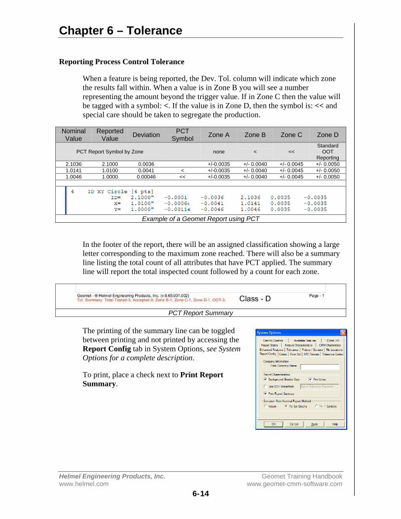
Chapter 6 – Tolerance
Helmel Engineering Products, Inc. Geomet Training Handbookwww.helmel.com www.geomet-cmm-software.com
6-14
Reporting Process Control Tolerance
When a feature is being reported, the Dev. Tol. column will indicate which zonethe results fall within. When a value is in Zone B you will see a numberrepresenting the amount beyond the trigger value. If in Zone C then the value willbe tagged with a symbol: <. If the value is in Zone D, then the symbol is: << andspecial care should be taken to segregate the production.
NominalValue
ReportedValue Deviation PCT
Symbol Zone A Zone B Zone C Zone D
PCT Report Symbol by Zone none < <<Standard
OOTReporting
2.1036 2.1000 0.0036 +/-0.0035 +/- 0.0040 +/- 0.0045 +/- 0.00501.0141 1.0100 0.0041 < +/-0.0035 +/- 0.0040 +/- 0.0045 +/- 0.00501.0046 1.0000 0.00046 << +/-0.0035 +/- 0.0040 +/- 0.0045 +/- 0.0050
Example of a Geomet Report using PCT
In the footer of the report, there will be an assigned classification showing a largeletter corresponding to the maximum zone reached. There will also be a summaryline listing the total count of all attributes that have PCT applied. The summaryline will report the total inspected count followed by a count for each zone.
PCT Report Summary
The printing of the summary line can be toggledbetween printing and not printed by accessing theReport Config tab in System Options, see SystemOptions for a complete description.
To print, place a check next to Print ReportSummary.

Chapter 6 – Tolerance
Helmel Engineering Products, Inc. Geomet Training Handbookwww.helmel.com www.geomet-cmm-software.com
6-15
Out-of-Tolerance Flash Message
The Out-of-Tolerance Notification function provides a flash message to theprimary system monitor at the end of an Inspection Run only when an Out-of-Tolerance condition exists.
The OOT Setup tool is located in the pull down menus [Tolerance->Out-of-TolNotification].
OOT Setup Box OOT Setup Message
To activate, place a check next to "Send a Flash to the Monitor". Upon acceptingthe change, <Ok>, you will be reminded where the message exists. The messageis in a Rich Text File format (*.rtf) and has a default file name of "OotToMon.rtf"and resides in the program folder where Geomet.exe is installed. In normalinstallations, the folder for Geomet is located at:
C:\Program Files\Helmel Engineering\Geomet 101
This file can be changed with Microsoft Word, WordPad or any application thatsupport RTF files. When saving, writeover the same file name and save as "rtf"format.
To create a high visibility for the FlashMessage, select the <Set Bk Color>button and assign a new background colorto your message.
The activation of the OOT Notification and color settings becomes part of yourcurrent inspection program, not a global state for all programs. After making yourchanges, save your current inspection file to ensure the changes become part ofthe inspection program.
Program Execution
Upon completion of an inspection run, Geomet will review all results that have atolerance applied and should it find one or more out-of-tolerance conditions,Geomet will flash the OOT Notification message to the screen.
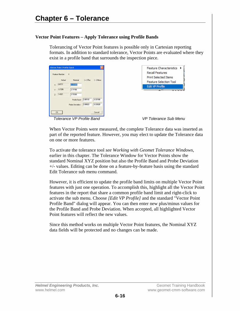
Chapter 6 – Tolerance
Helmel Engineering Products, Inc. Geomet Training Handbookwww.helmel.com www.geomet-cmm-software.com
6-16
Vector Point Features – Apply Tolerance using Profile Bands
Tolerancing of Vector Point features is possible only in Cartesian reportingformats. In addition to standard tolerance, Vector Points are evaluated where theyexist in a profile band that surrounds the inspection piece.
Tolerance VP Profile Band VP Tolerance Sub Menu
When Vector Points were measured, the complete Tolerance data was inserted aspart of the reported feature. However, you may elect to update the Tolerance dataon one or more features.
To activate the tolerance tool see Working with Geomet Tolerance Windows,earlier in this chapter. The Tolerance Window for Vector Points show thestandard Nominal XYZ position but also the Profile Band and Probe Deviation+/- values. Editing can be done on a feature-by-feature basis using the standardEdit Tolerance sub menu command.
However, it is efficient to update the profile band limits on multiple Vector Pointfeatures with just one operation. To accomplish this, highlight all the Vector Pointfeatures in the report that share a common profile band limit and right-click toactivate the sub menu. Choose [Edit VP Profile] and the standard "Vector PointProfile Band" dialog will appear. You can then enter new plus/minus values forthe Profile Band and Probe Deviation. When accepted, all highlighted VectorPoint features will reflect the new values.
Since this method works on multiple Vector Point features, the Nominal XYZdata fields will be protected and no changes can be made.
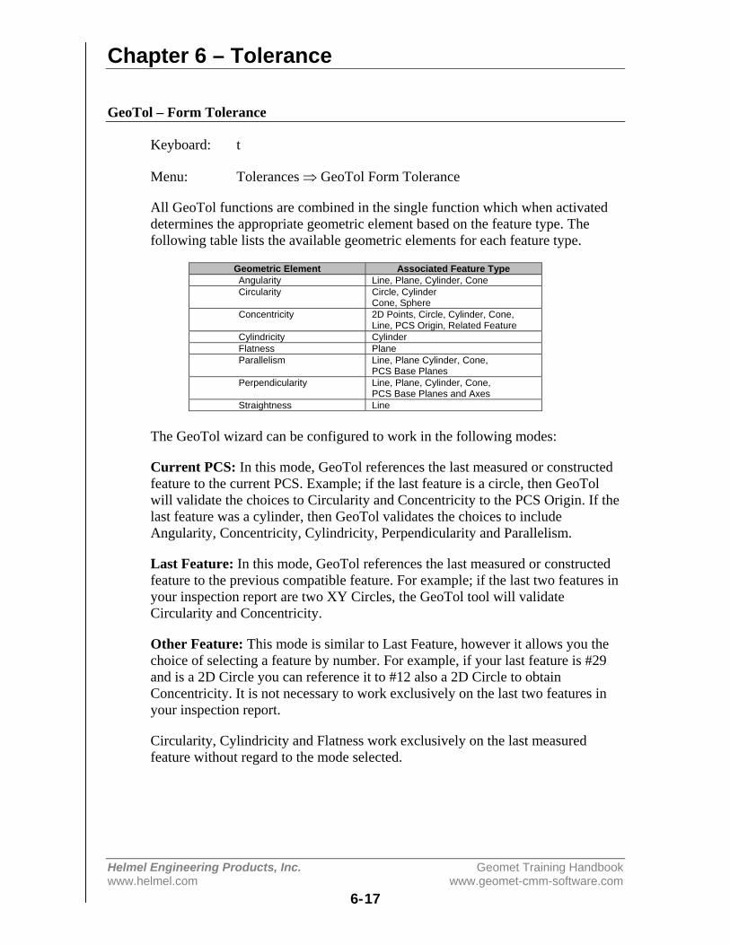
Chapter 6 – Tolerance
Helmel Engineering Products, Inc. Geomet Training Handbookwww.helmel.com www.geomet-cmm-software.com
6-17
GeoTol – Form Tolerance
Keyboard: t
Menu: Tolerances ⇒ GeoTol Form Tolerance
All GeoTol functions are combined in the single function which when activateddetermines the appropriate geometric element based on the feature type. Thefollowing table lists the available geometric elements for each feature type.
Geometric Element Associated Feature TypeAngularity Line, Plane, Cylinder, ConeCircularity Circle, Cylinder
Cone, SphereConcentricity 2D Points, Circle, Cylinder, Cone,
Line, PCS Origin, Related FeatureCylindricity CylinderFlatness PlaneParallelism Line, Plane Cylinder, Cone,
PCS Base PlanesPerpendicularity Line, Plane, Cylinder, Cone,
PCS Base Planes and AxesStraightness Line
The GeoTol wizard can be configured to work in the following modes:
Current PCS: In this mode, GeoTol references the last measured or constructedfeature to the current PCS. Example; if the last feature is a circle, then GeoTolwill validate the choices to Circularity and Concentricity to the PCS Origin. If thelast feature was a cylinder, then GeoTol validates the choices to includeAngularity, Concentricity, Cylindricity, Perpendicularity and Parallelism.
Last Feature: In this mode, GeoTol references the last measured or constructedfeature to the previous compatible feature. For example; if the last two features inyour inspection report are two XY Circles, the GeoTol tool will validateCircularity and Concentricity.
Other Feature: This mode is similar to Last Feature, however it allows you thechoice of selecting a feature by number. For example, if your last feature is #29and is a 2D Circle you can reference it to #12 also a 2D Circle to obtainConcentricity. It is not necessary to work exclusively on the last two features inyour inspection report.
Circularity, Cylindricity and Flatness work exclusively on the last measuredfeature without regard to the mode selected.
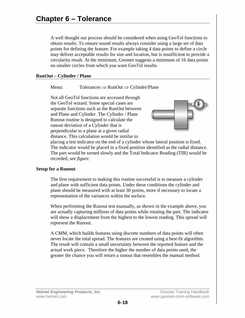
Chapter 6 – Tolerance
Helmel Engineering Products, Inc. Geomet Training Handbookwww.helmel.com www.geomet-cmm-software.com
6-18
A well thought out process should be considered when using GeoTol functions toobtain results. To ensure sound results always consider using a large set of datapoints for defining the feature. For example taking 4 data points to define a circlemay deliver acceptable results for size and location, but is insufficient to provide acircularity result. At the minimum, Geomet suggests a minimum of 16 data pointson smaller circles from which you want GeoTol results.
RunOut – Cylinder / Plane
Menu: Tolerances ⇒ RunOut ⇒ Cylinder/Plane
Not all GeoTol functions are accessed throughthe GeoTol wizard. Some special cases areseparate functions such as the RunOut betweenand Plane and Cylinder. The Cylinder / PlaneRunout routine is designed to calculate therunout deviation of a Cylinder that isperpendicular to a plane at a given radialdistance. This calculation would be similar toplacing a test indicator on the end of a cylinder whose lateral position is fixed.The indicator would be placed in a fixed position identified as the radial distance.The part would be turned slowly and the Total Indicator Reading (TIR) would berecorded, see figure.
Setup for a Runout
The first requirement to making this routine successful is to measure a cylinderand plane with sufficient data points. Under these conditions the cylinder andplane should be measured with at least 30 points, more if necessary to locate arepresentation of the variances within the surface.
When performing the Runout test manually, as shown in the example above, youare actually capturing millions of data points while rotating the part. The indicatorwill show a displacement from the highest to the lowest reading. This spread willrepresent the Runout.
A CMM, which builds features using discrete numbers of data points will oftennever locate the total spread. The features are created using a best-fit algorithm.The result will contain a small uncertainty between the reported feature and theactual work piece. Therefore the higher the number of data points used, thegreater the chance you will return a runout that resembles the manual method.
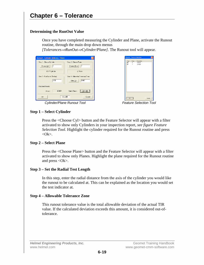
Chapter 6 – Tolerance
Helmel Engineering Products, Inc. Geomet Training Handbookwww.helmel.com www.geomet-cmm-software.com
6-19
Determining the RunOut Value
Once you have completed measuring the Cylinder and Plane, activate the Runoutroutine, through the main drop down menus[Tolerances⇒RunOut⇒Cylinder/Plane]. The Runout tool will appear.
Cylinder/Plane Runout Tool Feature Selection Tool
Step 1 – Select Cylinder
Press the <Choose Cyl> button and the Feature Selector will appear with a filteractivated to show only Cylinders in your inspection report, see figure FeatureSelection Tool. Highlight the cylinder required for the Runout routine and press<Ok>.
Step 2 – Select Plane
Press the <Choose Plane> button and the Feature Selector will appear with a filteractivated to show only Planes. Highlight the plane required for the Runout routineand press <Ok>.
Step 3 – Set the Radial Test Length
In this step, enter the radial distance from the axis of the cylinder you would likethe runout to be calculated at. This can be explained as the location you would setthe test indicator at.
Step 4 – Allowable Tolerance Zone
This runout tolerance value is the total allowable deviation of the actual TIRvalue. If the calculated deviation exceeds this amount, it is considered out-of-tolerance.
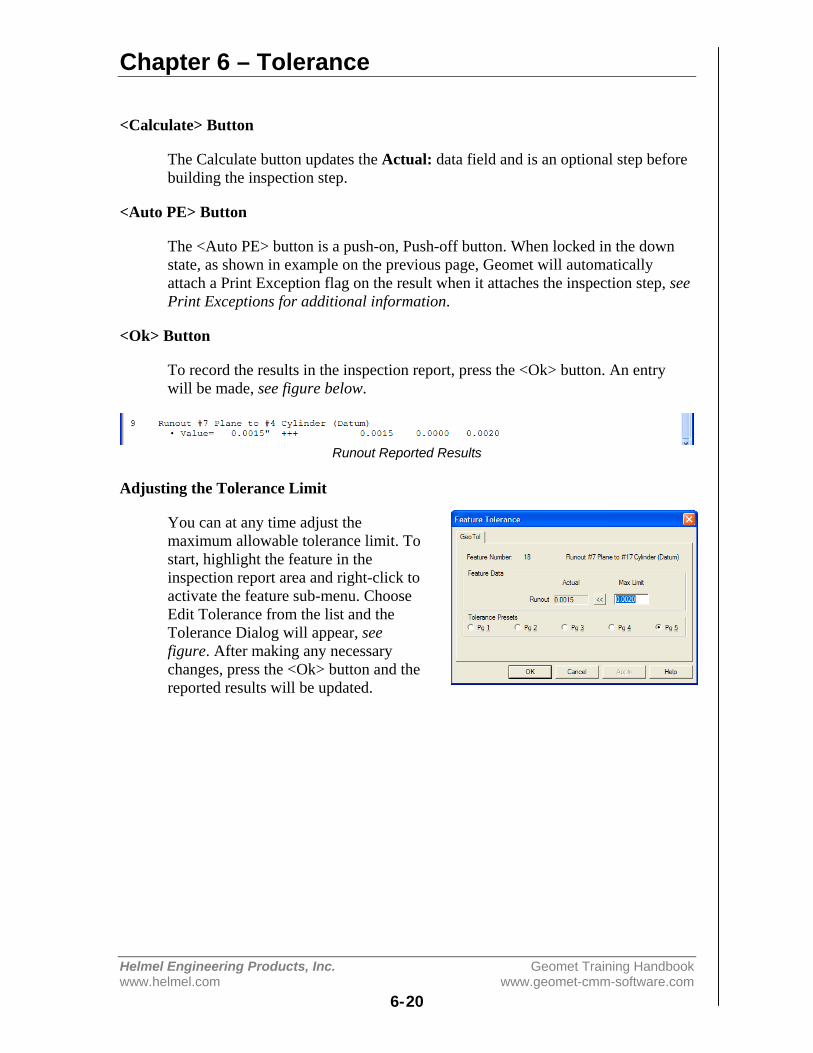
Chapter 6 – Tolerance
Helmel Engineering Products, Inc. Geomet Training Handbookwww.helmel.com www.geomet-cmm-software.com
6-20
<Calculate> Button
The Calculate button updates the Actual: data field and is an optional step beforebuilding the inspection step.
<Auto PE> Button
The <Auto PE> button is a push-on, Push-off button. When locked in the downstate, as shown in example on the previous page, Geomet will automaticallyattach a Print Exception flag on the result when it attaches the inspection step, seePrint Exceptions for additional information.
<Ok> Button
To record the results in the inspection report, press the <Ok> button. An entrywill be made, see figure below.
Runout Reported Results
Adjusting the Tolerance Limit
You can at any time adjust themaximum allowable tolerance limit. Tostart, highlight the feature in theinspection report area and right-click toactivate the feature sub-menu. ChooseEdit Tolerance from the list and theTolerance Dialog will appear, seefigure. After making any necessarychanges, press the <Ok> button and thereported results will be updated.
Chapter 7 – Constructions
Helmel Engineering Products, Inc. Geomet Training Handbookwww.helmel.com www.geomet-cmm-software.com
7-1
Chapter 7 – Constructions
Constructions – Brief Overview ........................................................ 7-2Selecting Features ........................................................................ 7-2Implicit Selection ......................................................................... 7-2Targeted Highlighting.................................................................. 7-2Feature Selection Tool ................................................................. 7-2
Bisect ................................................................................................. 7-3
Intersect.............................................................................................. 7-4General Features – Single Point Solutions .................................. 7-4Circle / Circle............................................................................... 7-4Circle Line ................................................................................... 7-6
Offset Features ................................................................................... 7-8Offset Point .................................................................................. 7-8Offset Line ................................................................................... 7-9Offset Plane................................................................................ 7-10
Angle................................................................................................ 7-11
Distance ........................................................................................... 7-12
Extended Distance ........................................................................... 7-13Reporting Format Control.......................................................... 7-13Circle / Circle............................................................................. 7-14Cylinder / Sphere ....................................................................... 7-163D Point / 3D Point.................................................................... 7-18
Boundary Planes .............................................................................. 7-19
Inscribed / Circumscribed Circle ..................................................... 7-20
Recall Feature .................................................................................. 7-21Recall Feature Tool.................................................................... 7-21On Demand Recall ..................................................................... 7-21
Recall PCS Base Components ......................................................... 7-22

Chapter 7 – Constructions
Helmel Engineering Products, Inc. Geomet Training Handbookwww.helmel.com www.geomet-cmm-software.com
7-2
Constructions
Geomet has the capability to create new features derived from other measured orconstructed entities. During the inspection process, features are often created tosolve complex solutions. The constructions available include:
BisectIntersectOffset FeaturesAnglesDistances
Selecting Features for Constructions
The process of selecting compatible features from your inspection for use with aConstruction command can be accomplished through three methods.
Method 1- Implicit Selection
This method assumes there are no highlighted features in your inspection report.The construction command will then work exclusively on the last two compatiblefeatures in your inspection report. The construction command will look throughtransparent features such as state changes, text and other non-geometry entriesand extract two measured or constructed features for use in the construction.
Method 2 – Targeted Highlighting
The operator may elect to highlight two random features then invoke theconstruction command. The construction command will extract those highlightedfeatures to solve for a solution. Care should be taken when selecting randomfeatures to follow the rules of compatibility. These rules vary based on theconstruction command being applied. Where utilizing 1D and 2D features, theselected features must share the same PCS, which is also the current PCS.
Method 3 – Feature Selection Tool
Geomet has a selection tool that is invoked with the <~> key press or menucommand [Construct ⇒ Feature Selector]. This is a tool that extracts a listingfrom the current inspection of all, or filtered features. Select from this list thefeatures you would like the construction command to work with. For moreinformation regarding the Feature Selector, please refer to chapter 8.
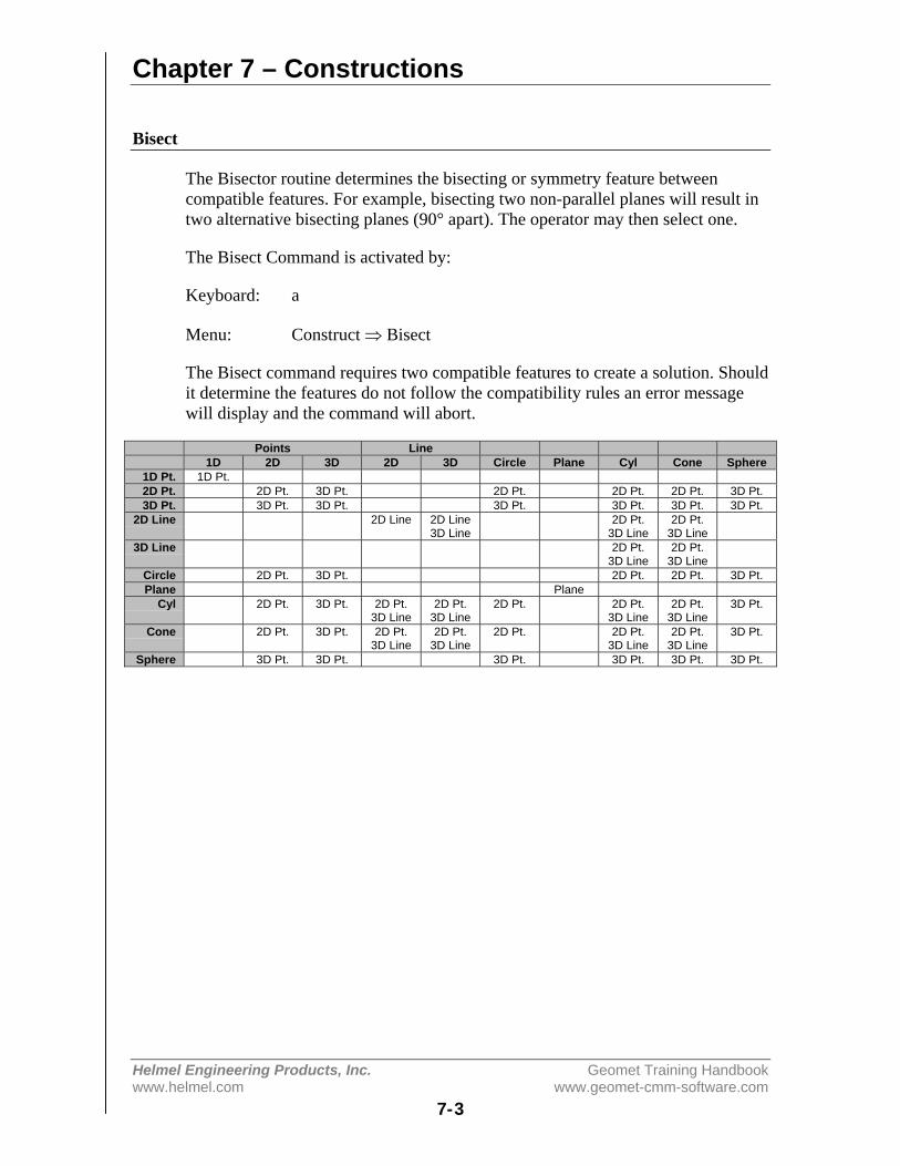
Chapter 7 – Constructions
Helmel Engineering Products, Inc. Geomet Training Handbookwww.helmel.com www.geomet-cmm-software.com
7-3
Bisect
The Bisector routine determines the bisecting or symmetry feature betweencompatible features. For example, bisecting two non-parallel planes will result intwo alternative bisecting planes (90° apart). The operator may then select one.
The Bisect Command is activated by:
Keyboard: a
Menu: Construct ⇒ Bisect
The Bisect command requires two compatible features to create a solution. Shouldit determine the features do not follow the compatibility rules an error messagewill display and the command will abort.
Points Line1D 2D 3D 2D 3D Circle Plane Cyl Cone Sphere
1D Pt. 1D Pt.2D Pt. 2D Pt. 3D Pt. 2D Pt. 2D Pt. 2D Pt. 3D Pt.3D Pt. 3D Pt. 3D Pt. 3D Pt. 3D Pt. 3D Pt. 3D Pt.
2D Line 2D Line 2D Line3D Line
2D Pt.3D Line
2D Pt.3D Line
3D Line 2D Pt.3D Line
2D Pt.3D Line
Circle 2D Pt. 3D Pt. 2D Pt. 2D Pt. 3D Pt.Plane Plane
Cyl 2D Pt. 3D Pt. 2D Pt.3D Line
2D Pt.3D Line
2D Pt. 2D Pt.3D Line
2D Pt.3D Line
3D Pt.
Cone 2D Pt. 3D Pt. 2D Pt.3D Line
2D Pt.3D Line
2D Pt. 2D Pt.3D Line
2D Pt.3D Line
3D Pt.
Sphere 3D Pt. 3D Pt. 3D Pt. 3D Pt. 3D Pt. 3D Pt.
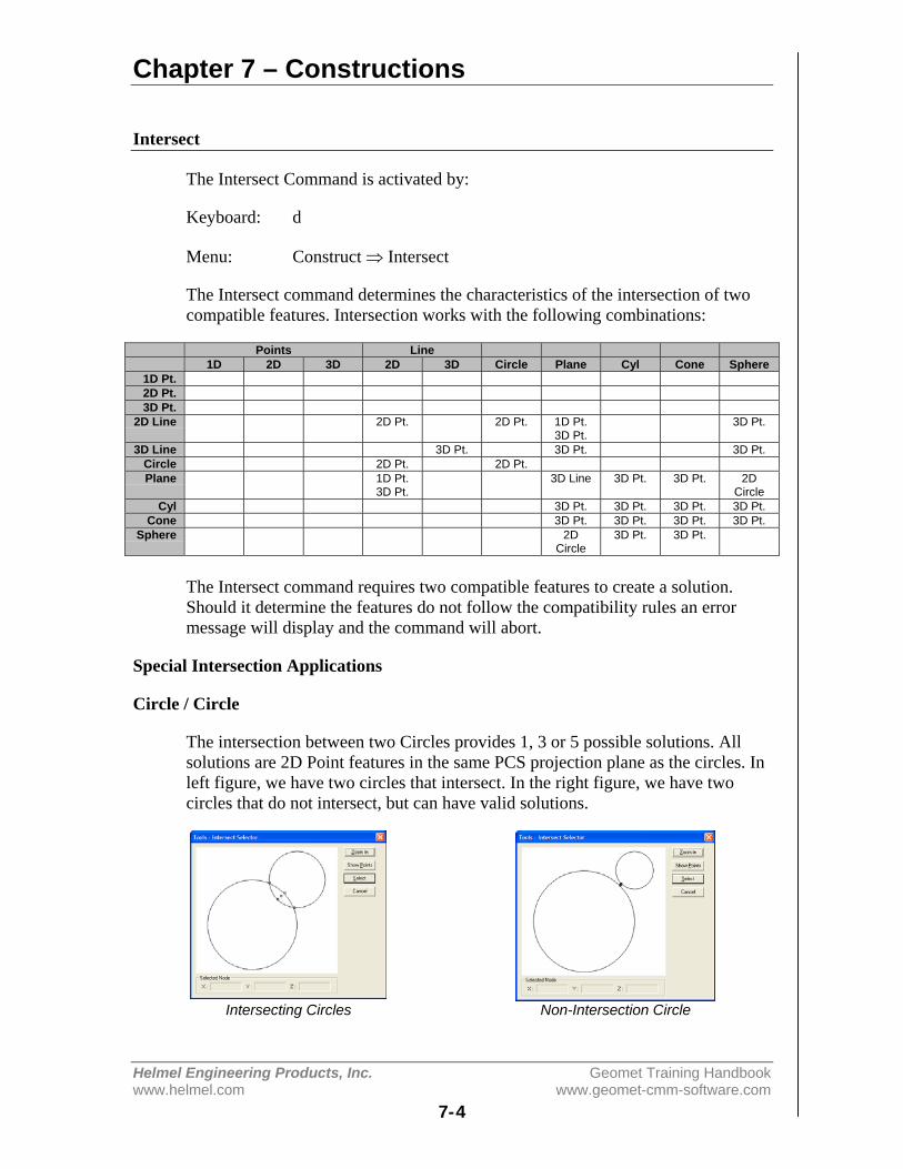
Chapter 7 – Constructions
Helmel Engineering Products, Inc. Geomet Training Handbookwww.helmel.com www.geomet-cmm-software.com
7-4
Intersect
The Intersect Command is activated by:
Keyboard: d
Menu: Construct ⇒ Intersect
The Intersect command determines the characteristics of the intersection of twocompatible features. Intersection works with the following combinations:
Points Line1D 2D 3D 2D 3D Circle Plane Cyl Cone Sphere
1D Pt.2D Pt.3D Pt.
2D Line 2D Pt. 2D Pt. 1D Pt.3D Pt.
3D Pt.
3D Line 3D Pt. 3D Pt. 3D Pt.Circle 2D Pt. 2D Pt.Plane 1D Pt.
3D Pt.3D Line 3D Pt. 3D Pt. 2D
CircleCyl 3D Pt. 3D Pt. 3D Pt. 3D Pt.
Cone 3D Pt. 3D Pt. 3D Pt. 3D Pt.Sphere 2D
Circle3D Pt. 3D Pt.
The Intersect command requires two compatible features to create a solution.Should it determine the features do not follow the compatibility rules an errormessage will display and the command will abort.
Special Intersection Applications
Circle / Circle
The intersection between two Circles provides 1, 3 or 5 possible solutions. Allsolutions are 2D Point features in the same PCS projection plane as the circles. Inleft figure, we have two circles that intersect. In the right figure, we have twocircles that do not intersect, but can have valid solutions.
Intersecting Circles Non-Intersection Circle
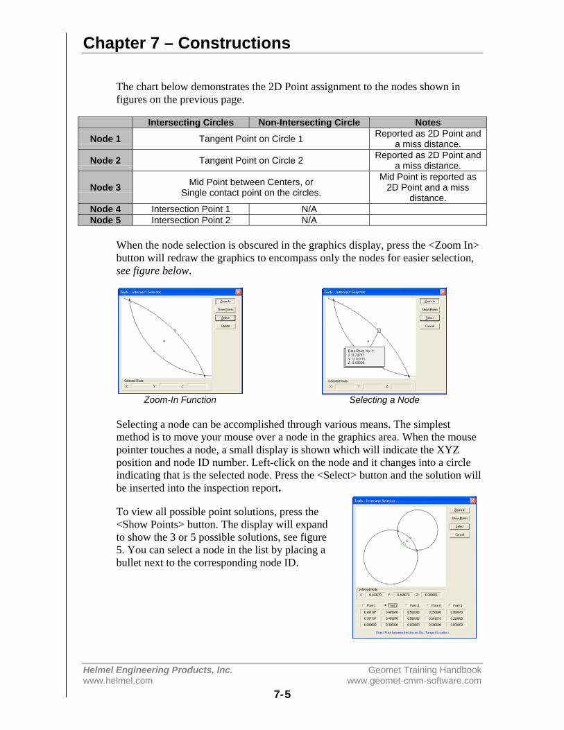
Chapter 7 – Constructions
Helmel Engineering Products, Inc. Geomet Training Handbookwww.helmel.com www.geomet-cmm-software.com
7-5
The chart below demonstrates the 2D Point assignment to the nodes shown infigures on the previous page.
Intersecting Circles Non-Intersecting Circle Notes
Node 1 Tangent Point on Circle 1 Reported as 2D Point anda miss distance.
Node 2 Tangent Point on Circle 2 Reported as 2D Point anda miss distance.
Node 3 Mid Point between Centers, orSingle contact point on the circles.
Mid Point is reported as2D Point and a miss
distance.Node 4 Intersection Point 1 N/ANode 5 Intersection Point 2 N/A
When the node selection is obscured in the graphics display, press the <Zoom In>button will redraw the graphics to encompass only the nodes for easier selection,see figure below.
Zoom-In Function Selecting a Node
Selecting a node can be accomplished through various means. The simplestmethod is to move your mouse over a node in the graphics area. When the mousepointer touches a node, a small display is shown which will indicate the XYZposition and node ID number. Left-click on the node and it changes into a circleindicating that is the selected node. Press the <Select> button and the solution willbe inserted into the inspection report.
To view all possible point solutions, press the<Show Points> button. The display will expandto show the 3 or 5 possible solutions, see figure5. You can select a node in the list by placing abullet next to the corresponding node ID.

Chapter 7 – Constructions
Helmel Engineering Products, Inc. Geomet Training Handbookwww.helmel.com www.geomet-cmm-software.com
7-6
Circle / Circle - Single Point Solution
There exists one condition that results in one intersect solution. That is where thecircles touch at only one point. When asking for the Intersection, the system willreport the one solution in your inspection report. This point corresponds to nodeID number 3 from the table above.
However, when capturing measured results this condition is rare. When Geometdetermines the two circle do not repeat the touching in only the one selectedpoint, or may not even intersect, the solution will default to the mid point andmiss distance.
Circle / Circle - Default Reporting
When teaching a part for auto-inspection, variances to the part duringmanufacturing may affect the reported intersection solution. For example, thecircle may intersect resulting in 5 possible solutions during the self-teach phase,but later during the inspection routine they fail to intersect resulting in 3 possiblesolutions.
If the original solution to report was node #4 or #5 when they intersected, theywill report as node #3 during inspection.
Circle / Line
The intersection between a Circle and Line provides 1, 3 or 5 possible solutions.All solutions are 2D Point features in the same PCS projection plane as thefeatures. In figure 6, we have two circles that intersect. In figure 7, we have twocircles that do not intersect, but can have valid solutions.
Intersecting Line/Circle Non- Intersecting Line/Circle
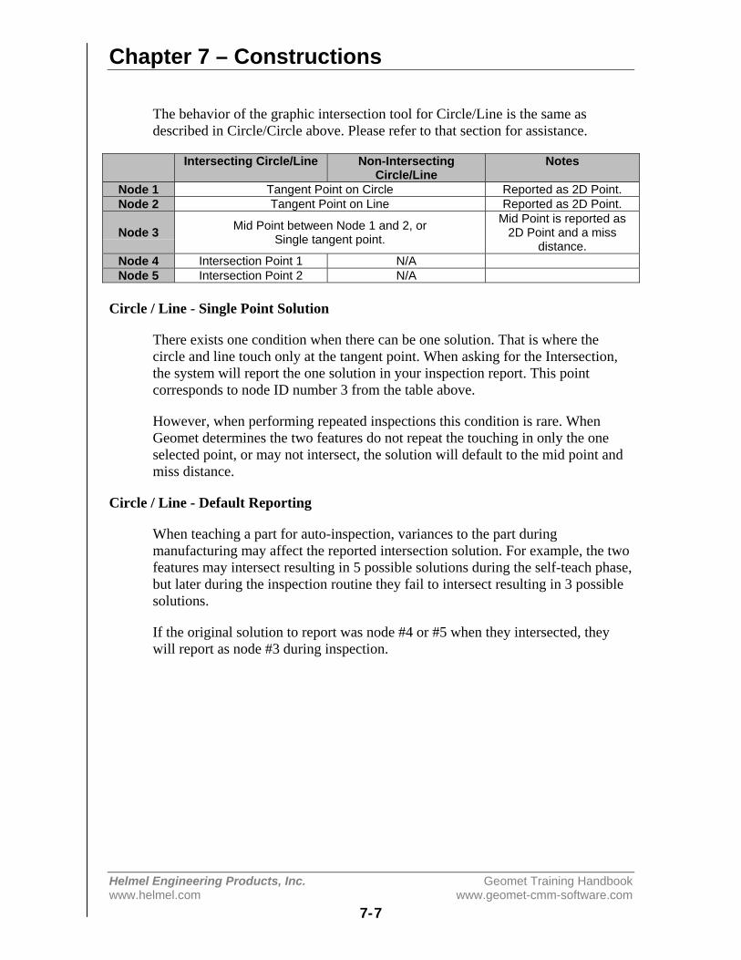
Chapter 7 – Constructions
Helmel Engineering Products, Inc. Geomet Training Handbookwww.helmel.com www.geomet-cmm-software.com
7-7
The behavior of the graphic intersection tool for Circle/Line is the same asdescribed in Circle/Circle above. Please refer to that section for assistance.
Intersecting Circle/Line Non-IntersectingCircle/Line
Notes
Node 1 Tangent Point on Circle Reported as 2D Point.Node 2 Tangent Point on Line Reported as 2D Point.
Node 3 Mid Point between Node 1 and 2, orSingle tangent point.
Mid Point is reported as2D Point and a miss
distance.Node 4 Intersection Point 1 N/ANode 5 Intersection Point 2 N/A
Circle / Line - Single Point Solution
There exists one condition when there can be one solution. That is where thecircle and line touch only at the tangent point. When asking for the Intersection,the system will report the one solution in your inspection report. This pointcorresponds to node ID number 3 from the table above.
However, when performing repeated inspections this condition is rare. WhenGeomet determines the two features do not repeat the touching in only the oneselected point, or may not intersect, the solution will default to the mid point andmiss distance.
Circle / Line - Default Reporting
When teaching a part for auto-inspection, variances to the part duringmanufacturing may affect the reported intersection solution. For example, the twofeatures may intersect resulting in 5 possible solutions during the self-teach phase,but later during the inspection routine they fail to intersect resulting in 3 possiblesolutions.
If the original solution to report was node #4 or #5 when they intersected, theywill report as node #3 during inspection.
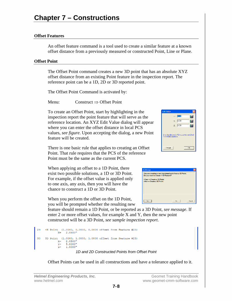
Chapter 7 – Constructions
Helmel Engineering Products, Inc. Geomet Training Handbookwww.helmel.com www.geomet-cmm-software.com
7-8
Offset Features
An offset feature command is a tool used to create a similar feature at a knownoffset distance from a previously measured or constructed Point, Line or Plane.
Offset Point
The Offset Point command creates a new 3D point that has an absolute XYZoffset distance from an existing Point feature in the inspection report. Thereference point can be a 1D, 2D or 3D reported point.
The Offset Point Command is activated by:
Menu: Construct ⇒ Offset Point
To create an Offset Point, start by highlighting in theinspection report the point feature that will serve as thereference location. An XYZ Edit Value dialog will appearwhere you can enter the offset distance in local PCSvalues, see figure. Upon accepting the dialog, a new Pointfeature will be created.
There is one basic rule that applies to creating an OffsetPoint. That rule requires that the PCS of the referencePoint must be the same as the current PCS.
When applying an offset to a 1D Point, thereexist two possible solutions, a 1D or 3D Point.For example, if the offset value is applied onlyto one axis, any axis, then you will have thechance to construct a 1D or 3D Point.
When you perform the offset on the 1D Point,you will be prompted whether the resulting newfeature should remain a 1D Point, or be reported as a 3D Point, see message. Ifenter 2 or more offset values, for example X and Y, then the new pointconstructed will be a 3D Point, see sample inspection report.
1D and 2D Constructed Points from Offset Point
Offset Points can be used in all constructions and have a tolerance applied to it.
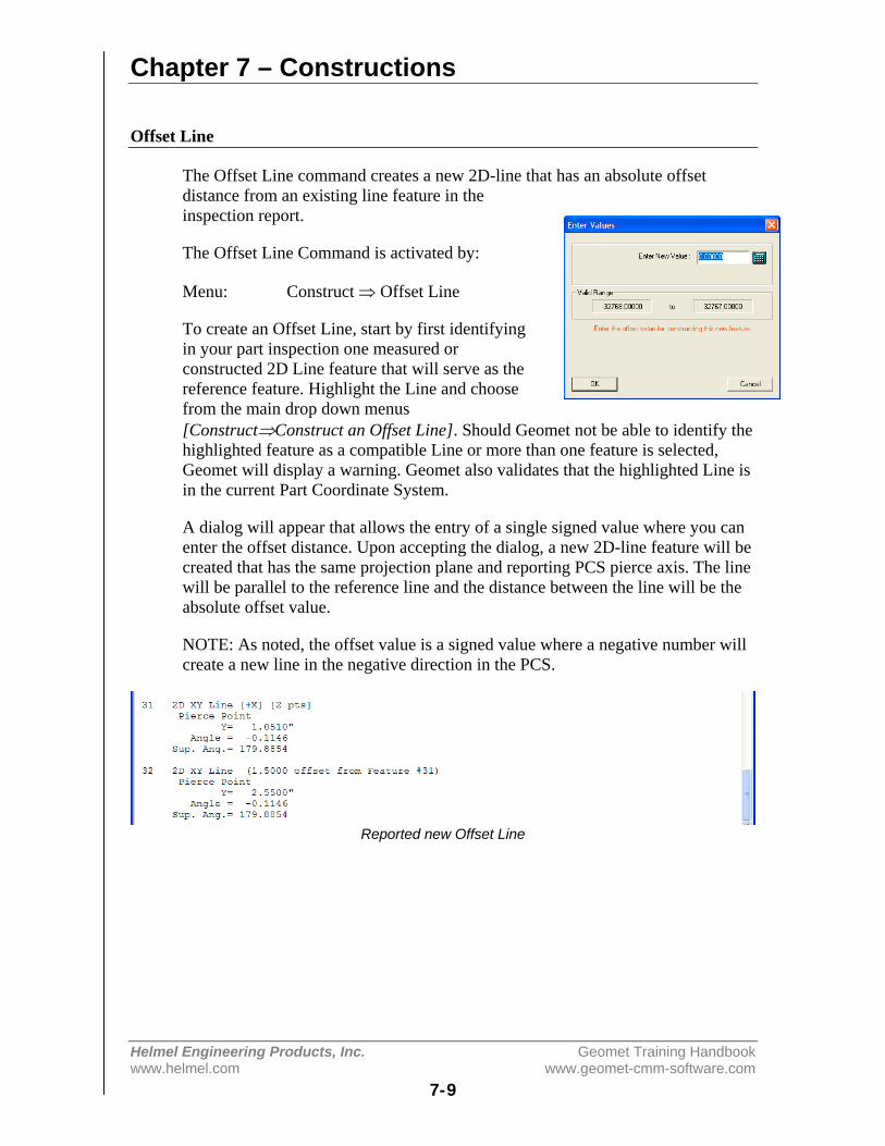
Chapter 7 – Constructions
Helmel Engineering Products, Inc. Geomet Training Handbookwww.helmel.com www.geomet-cmm-software.com
7-9
Offset Line
The Offset Line command creates a new 2D-line that has an absolute offsetdistance from an existing line feature in theinspection report.
The Offset Line Command is activated by:
Menu: Construct ⇒ Offset Line
To create an Offset Line, start by first identifyingin your part inspection one measured orconstructed 2D Line feature that will serve as thereference feature. Highlight the Line and choosefrom the main drop down menus[Construct⇒Construct an Offset Line]. Should Geomet not be able to identify thehighlighted feature as a compatible Line or more than one feature is selected,Geomet will display a warning. Geomet also validates that the highlighted Line isin the current Part Coordinate System.
A dialog will appear that allows the entry of a single signed value where you canenter the offset distance. Upon accepting the dialog, a new 2D-line feature will becreated that has the same projection plane and reporting PCS pierce axis. The linewill be parallel to the reference line and the distance between the line will be theabsolute offset value.
NOTE: As noted, the offset value is a signed value where a negative number willcreate a new line in the negative direction in the PCS.
Reported new Offset Line

Chapter 7 – Constructions
Helmel Engineering Products, Inc. Geomet Training Handbookwww.helmel.com www.geomet-cmm-software.com
7-10
Offset Plane
A previously measured or constructed plane can be used to create a parallel planespecified at a known distance. The offset plane can be used in all PCSconstructions, tolerance or other constructionrelated activities.
The Offset Plane Command is activated by:
Menu: Construct ⇒ Offset Plane
To create an Offset Plane, start by selecting inthe inspection report the plane feature that willserve as the reference feature. Highlight thatplane and choose from the drop down menus[Construct⇒Construct an Offset Plane]. A dialog will appear that allows theentry of a single signed value where you can enter the offset distance. Uponaccepting the dialog, a new plane feature will be created that has the sameprojection angles and reporting PCS pierce axis. The plane will be parallel to thereference plane and the distance between the line will be the absolute offset value.The Offset Plane command does not require that the PCS of the reference plane isthe same as the current PCS.
NOTE: As noted, the offset value is a signed value where a negative number willcreate a new plane in the negative direction of the PCS.
Reporting of an Offset Plane
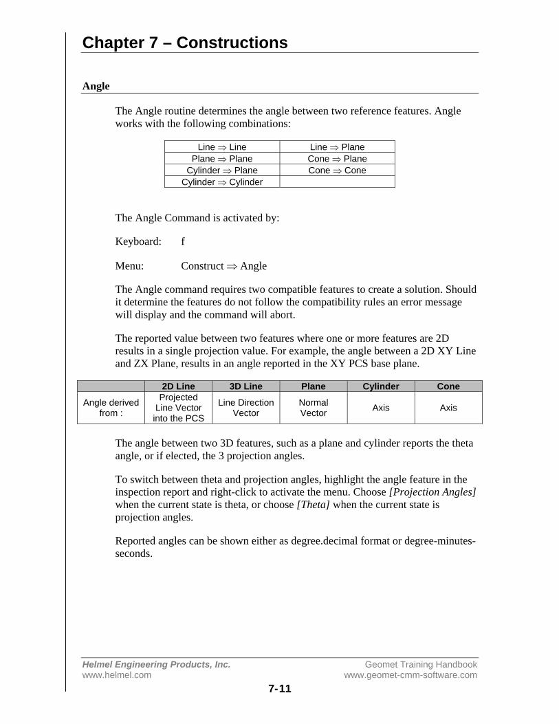
Chapter 7 – Constructions
Helmel Engineering Products, Inc. Geomet Training Handbookwww.helmel.com www.geomet-cmm-software.com
7-11
Angle
The Angle routine determines the angle between two reference features. Angleworks with the following combinations:
Line ⇒ Line Line ⇒ PlanePlane ⇒ Plane Cone ⇒ Plane
Cylinder ⇒ Plane Cone ⇒ ConeCylinder ⇒ Cylinder
The Angle Command is activated by:
Keyboard: f
Menu: Construct ⇒ Angle
The Angle command requires two compatible features to create a solution. Shouldit determine the features do not follow the compatibility rules an error messagewill display and the command will abort.
The reported value between two features where one or more features are 2Dresults in a single projection value. For example, the angle between a 2D XY Lineand ZX Plane, results in an angle reported in the XY PCS base plane.
2D Line 3D Line Plane Cylinder Cone
Angle derivedfrom :
ProjectedLine Vectorinto the PCS
Line DirectionVector
NormalVector Axis Axis
The angle between two 3D features, such as a plane and cylinder reports the thetaangle, or if elected, the 3 projection angles.
To switch between theta and projection angles, highlight the angle feature in theinspection report and right-click to activate the menu. Choose [Projection Angles]when the current state is theta, or choose [Theta] when the current state isprojection angles.
Reported angles can be shown either as degree.decimal format or degree-minutes-seconds.
Chapter 7 – Constructions
Helmel Engineering Products, Inc. Geomet Training Handbookwww.helmel.com www.geomet-cmm-software.com
7-12
Distance
The Distance Command is activated by:
Keyboard: s
Menu: Construct ⇒ Distance
Features must share a common axis and are contained in the current PartCoordinate System. For example a 2D XY Circle shares a common axis of Y witha 2D line reporting the Y-axis pierce value. The XY Cylinder Axis Pierce Pointshares both the X and Y with the reported position of a 3D Sphere.
Should the distance routine determine there are no shared axes between the twofeatures, an error will be reported. The Distance routine utilizes the currentReporting Format under the following conditions.
Reporting Formats
Cartesian: Calculates the results in X, Y, and/or Z values that are parallel to thecurrent Part Coordinate System.
Polar: Calculates the results in Radius and project angle components of 2D and3D distance solutions. Should the distance routine determine only a 1D solution ispossible, the reporting format will default to Cartesian.
Special considerations should be taken when using the Distance function. Forexample the distance between two -Z planes is calculated along the Z-axis of thecurrent Part Coordinate System. This may not reflect the desired results when thedata points used to calculate the planes are taken a distance from the PCS Origin.Any parallel deviation between the planes will accentuate the distance value whenprojecting to the Z-axis of the PCS.
The chart below illustrates the feature characteristics used in distance reporting.
FeatureType Reporting Characteristics
ReportingAxis
1D Point Reported position along the Current PCS Axis. 1D2D Point Projected 2D Point in the reported PCS Base plane. 2D3D Point Center XYZ Reported Position. 3D2D Circle Projected 2D Point in the reported PCS Base plane. 2D
2D Line Projected PCS Axis Pierce Point. 1D3D Line PCS Base Plane Pierce Point. 2D
Plane Project PCS Axis Pierce Point. 1DCylinder PCS Base Plane Pierce Point. 2D
Cone PCS Base Plane Pierce Point. 2DSphere Center XYZ Reported Position. 3D

Chapter 7 – Constructions
Helmel Engineering Products, Inc. Geomet Training Handbookwww.helmel.com www.geomet-cmm-software.com
7-13
Extended Distance
The Distance Command is activated by:
Keyboard: shift + s
Menu: Construct ⇒ Extended Distance
The Extended Distance routine expands the choices that can be used indetermining common axis distances between features with form. An examplewould be the outer distance between two circles, which result in a reported valueequal to the center-to-center distance plus the two radii.
The routine requires that features sharing reporting axis be used. For example twoXY Circles are acceptable, but a XY circle and a YZ circle are not. The onlynotable exceptions are a Cylinder/Sphere and two 3D Points. The explanation onthese special relationships is provided below.
Feature 1 Feature 2 Notes:Circle Circle Must be coplanar, distance
reported is in the commonPCS base plane.
Cylinder Sphere Distance reported isperpendicular to the Cylinderaxis, through the center of theSphere.
3D Point 3D Point Distance is reported as directline between 3D Points. Theform of the 3D Points is thesize of the Stylus used duringmeasuring.

Chapter 7 – Constructions
Helmel Engineering Products, Inc. Geomet Training Handbookwww.helmel.com www.geomet-cmm-software.com
7-14
Extended Distance Options
There are two basic controls that direct behavior of theExtended Distance tool. These are Reporting Formats andAlignments, see figure.
Reporting Formats:
Cartesian: Calculates the results in XYZ values that areparallel to the current Part Coordinate System.
Polar: Calculates the results in Radius and projectionangle components. The radius equals a direct line distancebetween the selected nodes. The angle is the projectedPCS base plane angle in the XY, ZX or YZ base plane.
Alignments:
Align in PCS: The calculated nodes are inline with the current Part CoordinateSystem. All reported results will be in PCS XYZ values.
Align with Features: The calculated nodes are inline with the direction vectorpassing through the center positions of the features. This method is commonlyused when combined with Polar reporting to show the inner or outside distancesof the features.
Tangent Points: The calculated nodes represent the point of contact of a linetouching both features simultaneously.
Using the Extended Distance Tool with Two Circles
Extended Distance works with the last two features measured or constructed, orwith two previously selected features in the inspection report.
Activating the Extended Distance Tool will show the two features in theirrespective orientation, see figure 1. Each circle will be shown with five nodesassigned corresponding to the top, bottom, right and left extreme positions, plus acenter point node. Between the two circles will exist a node that lies on a directline between the circle centers and its mid point.
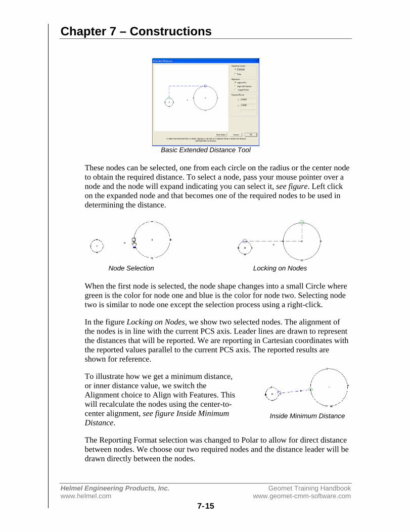
Chapter 7 – Constructions
Helmel Engineering Products, Inc. Geomet Training Handbookwww.helmel.com www.geomet-cmm-software.com
7-15
Basic Extended Distance Tool
These nodes can be selected, one from each circle on the radius or the center nodeto obtain the required distance. To select a node, pass your mouse pointer over anode and the node will expand indicating you can select it, see figure. Left clickon the expanded node and that becomes one of the required nodes to be used indetermining the distance.
Node Selection Locking on Nodes
When the first node is selected, the node shape changes into a small Circle wheregreen is the color for node one and blue is the color for node two. Selecting nodetwo is similar to node one except the selection process using a right-click.
In the figure Locking on Nodes, we show two selected nodes. The alignment ofthe nodes is in line with the current PCS axis. Leader lines are drawn to representthe distances that will be reported. We are reporting in Cartesian coordinates withthe reported values parallel to the current PCS axis. The reported results areshown for reference.
To illustrate how we get a minimum distance,or inner distance value, we switch theAlignment choice to Align with Features. Thiswill recalculate the nodes using the center-to-center alignment, see figure Inside MinimumDistance.
The Reporting Format selection was changed to Polar to allow for direct distancebetween nodes. We choose our two required nodes and the distance leader will bedrawn directly between the nodes.
Inside Minimum Distance
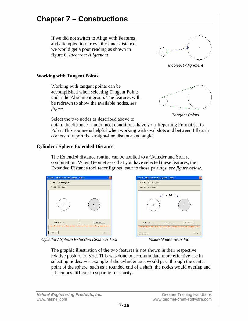
Chapter 7 – Constructions
Helmel Engineering Products, Inc. Geomet Training Handbookwww.helmel.com www.geomet-cmm-software.com
7-16
If we did not switch to Align with Featuresand attempted to retrieve the inner distance,we would get a poor reading as shown infigure 6, Incorrect Alignment.
Working with Tangent Points
Working with tangent points can beaccomplished when selecting Tangent Pointsunder the Alignment group. The features willbe redrawn to show the available nodes, seefigure.
Select the two nodes as described above toobtain the distance. Under most conditions, have your Reporting Format set toPolar. This routine is helpful when working with oval slots and between fillets incorners to report the straight-line distance and angle.
Cylinder / Sphere Extended Distance
The Extended distance routine can be applied to a Cylinder and Spherecombination. When Geomet sees that you have selected these features, theExtended Distance tool reconfigures itself to those pairings, see figure below.
Cylinder / Sphere Extended Distance Tool Inside Nodes Selected
The graphic illustration of the two features is not shown in their respectiverelative position or size. This was done to accommodate more effective use inselecting nodes. For example if the cylinder axis would pass through the centerpoint of the sphere, such as a rounded end of a shaft, the nodes would overlap andit becomes difficult to separate for clarity.
Incorrect Alignment
Tangent Points
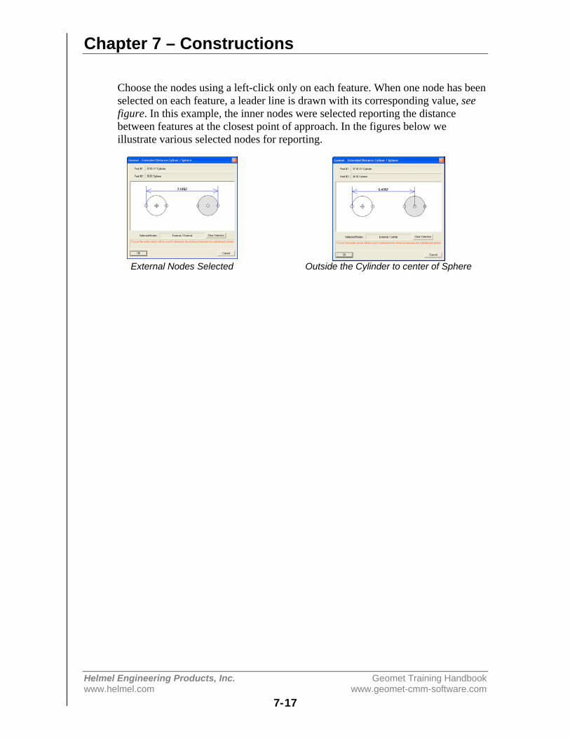
Chapter 7 – Constructions
Helmel Engineering Products, Inc. Geomet Training Handbookwww.helmel.com www.geomet-cmm-software.com
7-17
Choose the nodes using a left-click only on each feature. When one node has beenselected on each feature, a leader line is drawn with its corresponding value, seefigure. In this example, the inner nodes were selected reporting the distancebetween features at the closest point of approach. In the figures below weillustrate various selected nodes for reporting.
External Nodes Selected Outside the Cylinder to center of Sphere
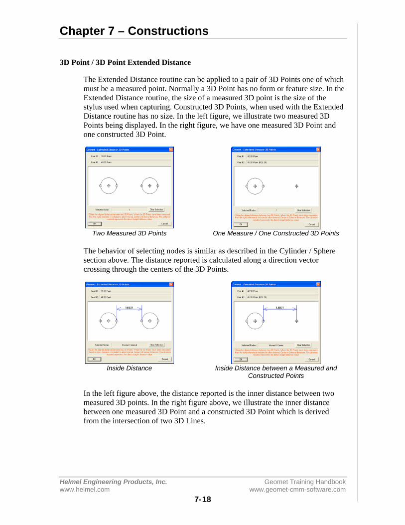
Chapter 7 – Constructions
Helmel Engineering Products, Inc. Geomet Training Handbookwww.helmel.com www.geomet-cmm-software.com
7-18
3D Point / 3D Point Extended Distance
The Extended Distance routine can be applied to a pair of 3D Points one of whichmust be a measured point. Normally a 3D Point has no form or feature size. In theExtended Distance routine, the size of a measured 3D point is the size of thestylus used when capturing. Constructed 3D Points, when used with the ExtendedDistance routine has no size. In the left figure, we illustrate two measured 3DPoints being displayed. In the right figure, we have one measured 3D Point andone constructed 3D Point.
Two Measured 3D Points One Measure / One Constructed 3D Points
The behavior of selecting nodes is similar as described in the Cylinder / Spheresection above. The distance reported is calculated along a direction vectorcrossing through the centers of the 3D Points.
Inside Distance Inside Distance between a Measured andConstructed Points
In the left figure above, the distance reported is the inner distance between twomeasured 3D points. In the right figure above, we illustrate the inner distancebetween one measured 3D Point and a constructed 3D Point which is derivedfrom the intersection of two 3D Lines.
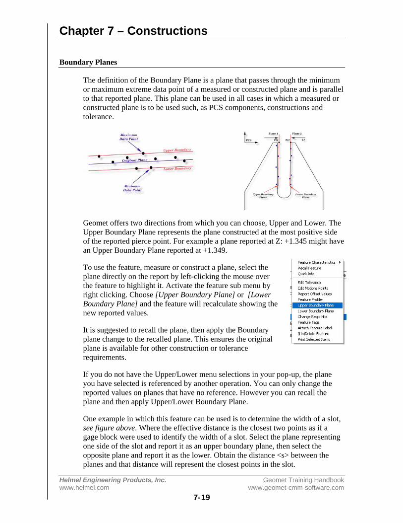
Chapter 7 – Constructions
Helmel Engineering Products, Inc. Geomet Training Handbookwww.helmel.com www.geomet-cmm-software.com
7-19
Boundary Planes
The definition of the Boundary Plane is a plane that passes through the minimumor maximum extreme data point of a measured or constructed plane and is parallelto that reported plane. This plane can be used in all cases in which a measured orconstructed plane is to be used such, as PCS components, constructions andtolerance.
Geomet offers two directions from which you can choose, Upper and Lower. TheUpper Boundary Plane represents the plane constructed at the most positive sideof the reported pierce point. For example a plane reported at Z: +1.345 might havean Upper Boundary Plane reported at +1.349.
To use the feature, measure or construct a plane, select theplane directly on the report by left-clicking the mouse overthe feature to highlight it. Activate the feature sub menu byright clicking. Choose [Upper Boundary Plane] or [LowerBoundary Plane] and the feature will recalculate showing thenew reported values.
It is suggested to recall the plane, then apply the Boundaryplane change to the recalled plane. This ensures the originalplane is available for other construction or tolerancerequirements.
If you do not have the Upper/Lower menu selections in your pop-up, the planeyou have selected is referenced by another operation. You can only change thereported values on planes that have no reference. However you can recall theplane and then apply Upper/Lower Boundary Plane.
One example in which this feature can be used is to determine the width of a slot,see figure above. Where the effective distance is the closest two points as if agage block were used to identify the width of a slot. Select the plane representingone side of the slot and report it as an upper boundary plane, then select theopposite plane and report it as the lower. Obtain the distance <s> between theplanes and that distance will represent the closest points in the slot.

Chapter 7 – Constructions
Helmel Engineering Products, Inc. Geomet Training Handbookwww.helmel.com www.geomet-cmm-software.com
7-20
Inscribed / Circumscribed Circle
The Inscribed Circle function evaluates the data points used to measure the circleand locates the inscribed and circumscribed circle solutions. The inscribed Circleis best used to illustrate a gage pin being inserted into a bore. The gage pin, whensized to the largest pin available to fit in the bore, will represent the maximuminscribed circle. The pin will contact the bore at three points representing theclosest points of contact.
The minimum Circumscribed Circle is best suited for use on outside features suchas a boss. This feature is best illustrated when using a ring gage to measure anoutside diameter. The solution is the smallest ring gage that will fit over theoutside diameter. The ring gage will contact the diameter at the three greatestpoints.
In both cases, the diameter reported will reflect these conditions. The position willalso vary from the normal best-fit solution of a circle.
Using the Inscribed / Circumscribed Circle Command
These features are a post operation on an already measured or constructed 2Dcircle. To use, highlight the circle in the inspection report and right click toactivate the sub menu. Locate either the Minimum or Maximum Inscribed Circlefeature as required.
Once you select your choice, the circle will appear in the inspection report as anInscribed Circle. In most cases, we recommend that you perform a recall on theoriginal circle, then apply the Inscribed Circle feature. That will preserve theoriginal values for comparison.
If you require removing the Inscribed Circle feature and revert it back to a normalbest-fit circle highlight the Inscribed Circle in the report and right click to activatethe sub menu. Choose [Remove Inscribed Circle].
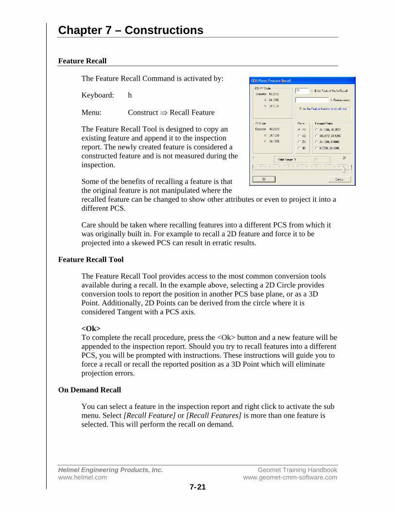
Chapter 7 – Constructions
Helmel Engineering Products, Inc. Geomet Training Handbookwww.helmel.com www.geomet-cmm-software.com
7-21
Feature Recall
The Feature Recall Command is activated by:
Keyboard: h
Menu: Construct ⇒ Recall Feature
The Feature Recall Tool is designed to copy anexisting feature and append it to the inspectionreport. The newly created feature is considered aconstructed feature and is not measured during theinspection.
Some of the benefits of recalling a feature is thatthe original feature is not manipulated where therecalled feature can be changed to show other attributes or even to project it into adifferent PCS.
Care should be taken where recalling features into a different PCS from which itwas originally built in. For example to recall a 2D feature and force it to beprojected into a skewed PCS can result in erratic results.
Feature Recall Tool
The Feature Recall Tool provides access to the most common conversion toolsavailable during a recall. In the example above, selecting a 2D Circle providesconversion tools to report the position in another PCS base plane, or as a 3DPoint. Additionally, 2D Points can be derived from the circle where it isconsidered Tangent with a PCS axis.
<Ok>To complete the recall procedure, press the <Ok> button and a new feature will beappended to the inspection report. Should you try to recall features into a differentPCS, you will be prompted with instructions. These instructions will guide you toforce a recall or recall the reported position as a 3D Point which will eliminateprojection errors.
On Demand Recall
You can select a feature in the inspection report and right click to activate the submenu. Select [Recall Feature] or [Recall Features] is more than one feature isselected. This will perform the recall on demand.

Chapter 7 – Constructions
Helmel Engineering Products, Inc. Geomet Training Handbookwww.helmel.com www.geomet-cmm-software.com
7-22
Recall PCS Base Components
The Recall PCS Base Components Command is activated by:
Keyboard: shift + H
Menu: Construct ⇒ Recall PCS Base Components
Part Coordinate Systems contains 3 orthogonal planes that define the XY, YZ andZX base planes. There is also a 3D Point that defines the origin. Thesecomponents can be recalled as constructed features.
Select a PCS Choose Component
When you activate the command you will be prompted to choose a PCS by itsnumber. If there is only one PCS, this step will be skipped automatically. The nexttool will allow you to choose one of the PCS components. Your choices are:
Button DescriptionXY Recalls a XY PlaneYZ Recalls a YZ PlaneZX Recalls a ZX Plane3D Recalls a the Origin as a 3D Point
The features created are compatible with all construction and tolerance tools.
Chapter 8 – Support Tools and Features
Helmel Engineering Products, Inc. Geomet Training Handbookwww.helmel.com www.geomet-cmm-software.com
8-1
Chapter 8 – Support Tools and Features
Understanding Auto Direction Sensing ............................................. 8-3Activate Auto Direction Sensing ................................................. 8-4
Program Header ................................................................................. 8-5Fixture Usage Data Fields............................................................ 8-6
Restart Program Header..................................................................... 8-7Rerun Step Selection, Manual and DCC CMMs ......................... 8-7
EZ Launch Menu System................................................................... 8-8Activating the EZ Launch Menu System..................................... 8-8Creating and Editing Cradle Definitions...................................... 8-8Cradle Definitions........................................................................ 8-9Editing Cradle Definitions ......................................................... 8-10Assign and FCS to a Cradle ....................................................... 8-12Assign Inspection Files to a Cradle ........................................... 8-13EZ Launch Polling System ........................................................ 8-15EZ Launch Operational Sequence ............................................. 8-18
Feature Selection Tool ..................................................................... 8-19Using PCS Filters....................................................................... 8-19Display only Measured and Constructed Features..................... 8-20Column Sorting.......................................................................... 8-20Applying your Selections........................................................... 8-20Math Function............................................................................ 8-21Diameter Averaging................................................................... 8-22Stylus Size Updating using a Ring Gage ................................... 8-22DCC Option Menu..................................................................... 8-23Rerun Feature Selector – Manual CMMs .................................. 8-24
Text Features.................................................................................... 8-25Manual Step Text Entry ............................................................. 8-25Basic Text .................................................................................. 8-27User Prompt with Image Support .............................................. 8-28In-Line Text Entry ..................................................................... 8-29
Custom Ordered Reports ................................................................. 8-31
Concise Reports ............................................................................... 8-34
Report Control Center...................................................................... 8-36
Print Exception / SPC Tags.............................................................. 8-37
Chapter 8 – Support Tools and Features
Helmel Engineering Products, Inc. Geomet Training Handbookwww.helmel.com www.geomet-cmm-software.com
8-2
Report Offset.................................................................................... 8-41
Digital Readout ................................................................................ 8-42Standard DRO............................................................................ 8-42Full DRO.................................................................................... 8-44
In-Line Math Calculator .................................................................. 8-46
GeoPlus Library ............................................................................... 8-48
Inspection Program Editing Tools ................................................... 8-53Undo........................................................................................... 8-53Delete ......................................................................................... 8-53Delete Permanently.................................................................... 8-55Delete All After.......................................................................... 8-56Edit History Tool ....................................................................... 8-57Insert .......................................................................................... 8-59Move .......................................................................................... 8-60Copy and Append ...................................................................... 8-61Jump to Feature Number............................................................ 8-62
Feature Properties ............................................................................ 8-63Single Feature Selection Submenu ............................................ 8-63Single Feature Property Tool ..................................................... 8-64Multiple Selected Features Submenu......................................... 8-65
Report Navigation Keys................................................................... 8-67
File Archive ..................................................................................... 8-68

Chapter 8 – Support Tools and Features
Helmel Engineering Products, Inc. Geomet Training Handbookwww.helmel.com www.geomet-cmm-software.com
8-3
Understanding Auto Direction Sensing
Using auto direction on 1D Points can lead to erroneous reported values if usedincorrectly. Auto direction relies on a smooth approach, from you the operator, incapturing of a data point. The process of determining the approach vectorinvolves the CMM interface card to maintain a rolling IJK vector based on the lastfive reported values. The interface card updates the current position in the MCSon a programmable time interval from 20 to 200 milliseconds.
Auto Direction Approach vector
When you are approaching your work piece, it is required that you make contactwhile remaining in a ±45° approach, see figure above. In this example, if weremained in the approach zone we will capture a data point that will be reportedas a +Y point. If the operator did not remain in the approach zone the 1D Pointmight report a + or - X Point from which we will have to correct the probecompensation error. Most common occurrence of an erroneous data point comesfrom operators who approach the surface, and then pause during the approach andattempt to make contact under extremely slow speeds, which causes variations inthe path toward the surface.
1D Point Correction Sub-menu (both styles shown)

Chapter 8 – Support Tools and Features
Helmel Engineering Products, Inc. Geomet Training Handbookwww.helmel.com www.geomet-cmm-software.com
8-4
To correct the reported direction of a 1D Point, highlight the feature by leftclicking on it, then right-click to bring up the feature menu, as shown in theprevious figure. Select [Point Direction], which will offer a sub-menu, with allsix probing directions available. Choose the correct 1D Point direction and yourpart inspection will update with the correct 1D Point. Note: Once a feature hasbeen referenced it can not be changed or edited. For example, if a feature wasused in the construction of a PCS, it will be locked from changes. This isidentified by the inclusion of a ¹ next to the feature number, example " 12¹ ".
Using Auto-Direction with multi-point features such as circle, lines and planescan also incorrectly report feature characteristics. This occurs when capturing datapoints inconsistently or by capturing data points at a high rate. As previouslymentioned, the calculation of the direction vector for the probe works off thespeed of the interface and should that rate of point capture be too high, thechanges in direction going toward, then backing off the data point will create apoor direction vector.
Since touch probes can be effected by speed and our auto-direction tool is alsoadversely effected by speed, we suggest the use of a smooth consistent approachspeed and rate when capturing data points.
Activate Auto Direction Sensing
Activate the Auto Direction sensing by going to the System Options, <F9> or[System⇒System Options] from the drop down menu. Locate the EnhancedFeature tab and place a check next to Enable Auto Sensing. If your CMMinterface does not supports Auto Direction Sensing, the check mark will clearautomatically.
During the inspection process you may require to control the Auto Directionsensing manually. This can be accomplished through the Feature MeasurementToolbar or by pressing the <u> key on the keyboard. The iconic button on thetoolbar will indicate the status of the sensing option. In right figure below, thebutton shows an "X" through the button. This indicates that if the button waspressed, you will take sensing off.
Turn Auto Direction Off Turn Auto Direction On
Although the visual appearance of these iconic buttons appears to be backward itactually represents what the button will do should it be pressed. The button is notdesigned to represent the current state of the Auto Direction Sensing.
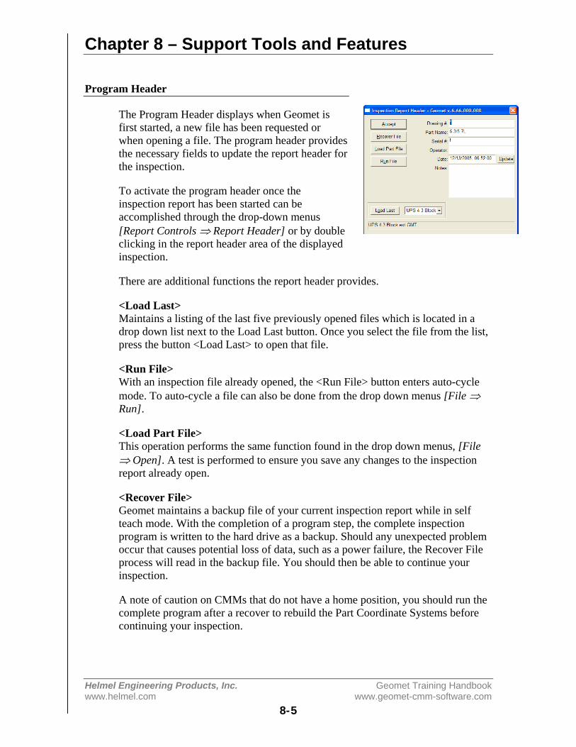
Chapter 8 – Support Tools and Features
Helmel Engineering Products, Inc. Geomet Training Handbookwww.helmel.com www.geomet-cmm-software.com
8-5
Program Header
The Program Header displays when Geomet isfirst started, a new file has been requested orwhen opening a file. The program header providesthe necessary fields to update the report header forthe inspection.
To activate the program header once theinspection report has been started can beaccomplished through the drop-down menus[Report Controls ⇒ Report Header] or by doubleclicking in the report header area of the displayedinspection.
There are additional functions the report header provides.
<Load Last>Maintains a listing of the last five previously opened files which is located in adrop down list next to the Load Last button. Once you select the file from the list,press the button <Load Last> to open that file.
<Run File>With an inspection file already opened, the <Run File> button enters auto-cyclemode. To auto-cycle a file can also be done from the drop down menus [File ⇒Run].
<Load Part File>This operation performs the same function found in the drop down menus, [File⇒ Open]. A test is performed to ensure you save any changes to the inspectionreport already open.
<Recover File>Geomet maintains a backup file of your current inspection report while in selfteach mode. With the completion of a program step, the complete inspectionprogram is written to the hard drive as a backup. Should any unexpected problemoccur that causes potential loss of data, such as a power failure, the Recover Fileprocess will read in the backup file. You should then be able to continue yourinspection.
A note of caution on CMMs that do not have a home position, you should run thecomplete program after a recover to rebuild the Part Coordinate Systems beforecontinuing your inspection.
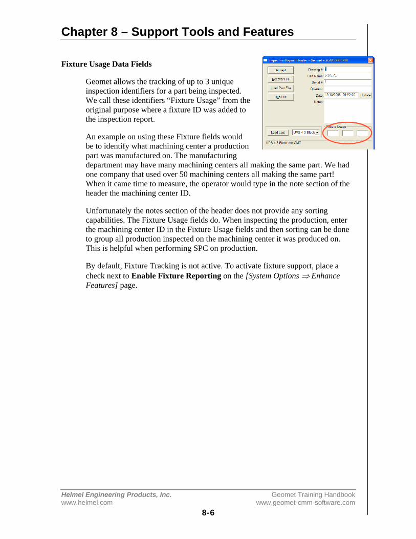
Chapter 8 – Support Tools and Features
Helmel Engineering Products, Inc. Geomet Training Handbookwww.helmel.com www.geomet-cmm-software.com
8-6
Fixture Usage Data Fields
Geomet allows the tracking of up to 3 uniqueinspection identifiers for a part being inspected.We call these identifiers “Fixture Usage” from theoriginal purpose where a fixture ID was added tothe inspection report.
An example on using these Fixture fields wouldbe to identify what machining center a productionpart was manufactured on. The manufacturingdepartment may have many machining centers all making the same part. We hadone company that used over 50 machining centers all making the same part!When it came time to measure, the operator would type in the note section of theheader the machining center ID.
Unfortunately the notes section of the header does not provide any sortingcapabilities. The Fixture Usage fields do. When inspecting the production, enterthe machining center ID in the Fixture Usage fields and then sorting can be doneto group all production inspected on the machining center it was produced on.This is helpful when performing SPC on production.
By default, Fixture Tracking is not active. To activate fixture support, place acheck next to Enable Fixture Reporting on the [System Options ⇒ EnhanceFeatures] page.
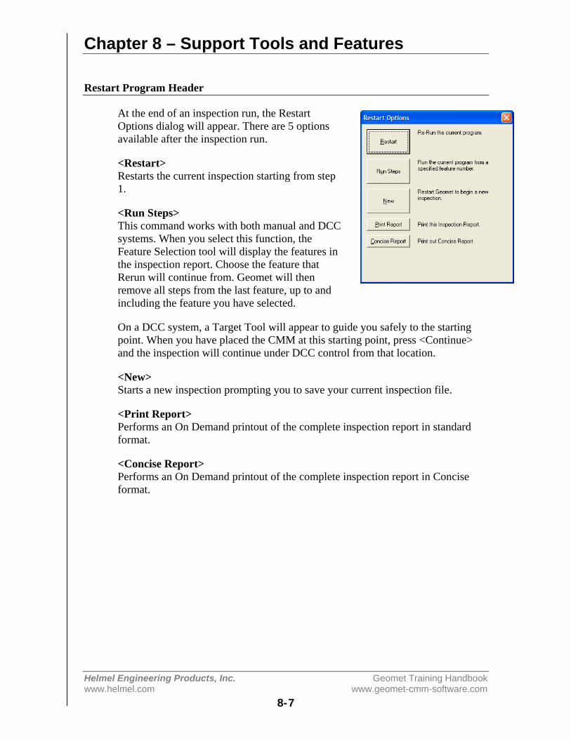
Chapter 8 – Support Tools and Features
Helmel Engineering Products, Inc. Geomet Training Handbookwww.helmel.com www.geomet-cmm-software.com
8-7
Restart Program Header
At the end of an inspection run, the RestartOptions dialog will appear. There are 5 optionsavailable after the inspection run.
<Restart>Restarts the current inspection starting from step1.
<Run Steps>This command works with both manual and DCCsystems. When you select this function, theFeature Selection tool will display the features inthe inspection report. Choose the feature thatRerun will continue from. Geomet will thenremove all steps from the last feature, up to andincluding the feature you have selected.
On a DCC system, a Target Tool will appear to guide you safely to the startingpoint. When you have placed the CMM at this starting point, press <Continue>and the inspection will continue under DCC control from that location.
<New>Starts a new inspection prompting you to save your current inspection file.
<Print Report>Performs an On Demand printout of the complete inspection report in standardformat.
<Concise Report>Performs an On Demand printout of the complete inspection report in Conciseformat.
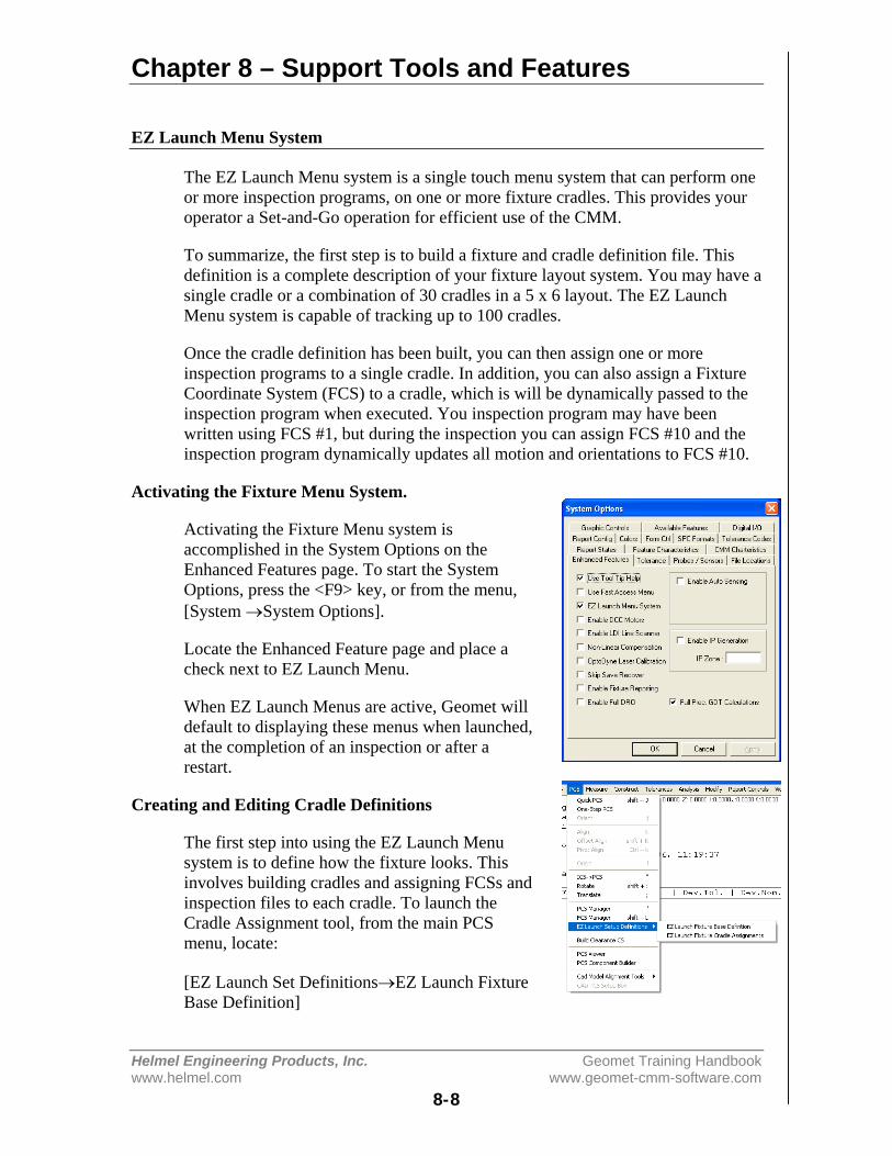
Chapter 8 – Support Tools and Features
Helmel Engineering Products, Inc. Geomet Training Handbookwww.helmel.com www.geomet-cmm-software.com
8-8
EZ Launch Menu System
The EZ Launch Menu system is a single touch menu system that can perform oneor more inspection programs, on one or more fixture cradles. This provides youroperator a Set-and-Go operation for efficient use of the CMM.
To summarize, the first step is to build a fixture and cradle definition file. Thisdefinition is a complete description of your fixture layout system. You may have asingle cradle or a combination of 30 cradles in a 5 x 6 layout. The EZ LaunchMenu system is capable of tracking up to 100 cradles.
Once the cradle definition has been built, you can then assign one or moreinspection programs to a single cradle. In addition, you can also assign a FixtureCoordinate System (FCS) to a cradle, which is will be dynamically passed to theinspection program when executed. You inspection program may have beenwritten using FCS #1, but during the inspection you can assign FCS #10 and theinspection program dynamically updates all motion and orientations to FCS #10.
Activating the Fixture Menu System.
Activating the Fixture Menu system isaccomplished in the System Options on theEnhanced Features page. To start the SystemOptions, press the <F9> key, or from the menu,[System →System Options].
Locate the Enhanced Feature page and place acheck next to EZ Launch Menu.
When EZ Launch Menus are active, Geomet willdefault to displaying these menus when launched,at the completion of an inspection or after arestart.
Creating and Editing Cradle Definitions
The first step into using the EZ Launch Menusystem is to define how the fixture looks. Thisinvolves building cradles and assigning FCSs andinspection files to each cradle. To launch theCradle Assignment tool, from the main PCSmenu, locate:
[EZ Launch Set Definitions→EZ Launch FixtureBase Definition]
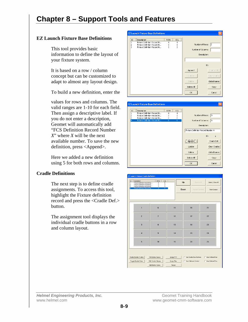
Chapter 8 – Support Tools and Features
Helmel Engineering Products, Inc. Geomet Training Handbookwww.helmel.com www.geomet-cmm-software.com
8-9
EZ Launch Fixture Base Definitions
This tool provides basicinformation to define the layout ofyour fixture system.
It is based on a row / columnconcept but can be customized toadapt to almost any layout design.
To build a new definition, enter the
values for rows and columns. Thevalid ranges are 1-10 for each field.Then assign a descriptive label. Ifyou do not enter a description,Geomet will automatically add“FCS Definition Record NumberX” where X will be the nextavailable number. To save the newdefinition, press <Append>.
Here we added a new definitionusing 5 for both rows and columns.
Cradle Definitions
The next step is to define cradleassignments. To access this tool,highlight the Fixture definitionrecord and press the <Cradle Def.>button.
The assignment tool displays theindividual cradle buttons in a rowand column layout.

Chapter 8 – Support Tools and Features
Helmel Engineering Products, Inc. Geomet Training Handbookwww.helmel.com www.geomet-cmm-software.com
8-10
Enable / Disable Cradles
This option lets you control thestate of a cradle. When you disablea cradle it is removed from thefinal menu and can no longer beaccessed by the operator.
To change the enable / disablestate, press the <Enable/DisableCradles> button. Each cradle willchange its label to reflect itscurrent state. Click on a cradle totoggle its state.
When you have completed yourchanges, press the <Enable/DisableCradles> button again to commityour changes as shown here.
We have removed from the activestate cradles 1, 7 and 13.
Toggle Disable State
This command will change thestate on each cradle between theEnabled and Disabled state.However, any cradle that hasinspection files assigned will stayin the Enabled state.
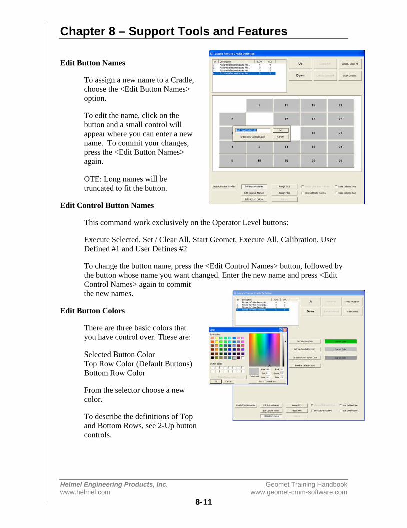
Chapter 8 – Support Tools and Features
Helmel Engineering Products, Inc. Geomet Training Handbookwww.helmel.com www.geomet-cmm-software.com
8-11
Edit Button Names
To assign a new name to a Cradle,choose the <Edit Button Names>option.
To edit the name, click on thebutton and a small control willappear where you can enter a newname. To commit your changes,press the <Edit Button Names>again.
OTE: Long names will betruncated to fit the button.
Edit Control Button Names
This command work exclusively on the Operator Level buttons:
Execute Selected, Set / Clear All, Start Geomet, Execute All, Calibration, UserDefined #1 and User Defines #2
To change the button name, press the <Edit Control Names> button, followed bythe button whose name you want changed. Enter the new name and press <EditControl Names> again to committhe new names.
Edit Button Colors
There are three basic colors thatyou have control over. These are:
Selected Button ColorTop Row Color (Default Buttons)Bottom Row Color
From the selector choose a newcolor.
To describe the definitions of Topand Bottom Rows, see 2-Up buttoncontrols.
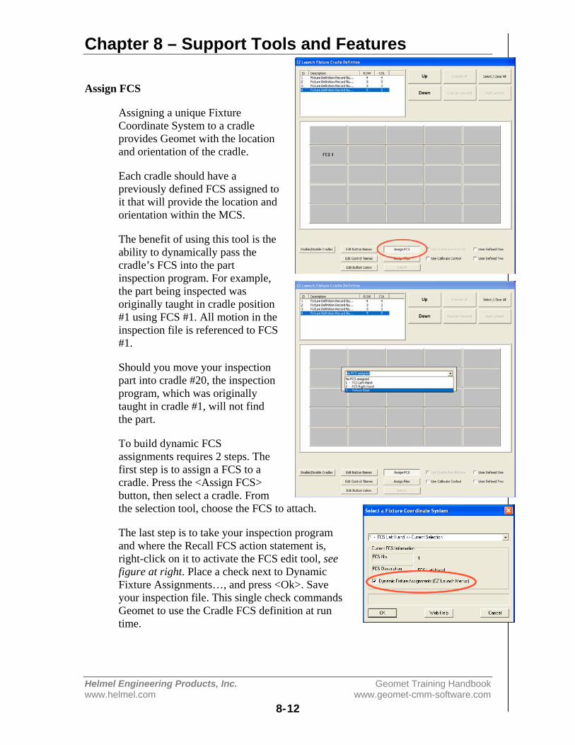
Chapter 8 – Support Tools and Features
Helmel Engineering Products, Inc. Geomet Training Handbookwww.helmel.com www.geomet-cmm-software.com
8-12
Assign FCS
Assigning a unique FixtureCoordinate System to a cradleprovides Geomet with the locationand orientation of the cradle.
Each cradle should have apreviously defined FCS assigned toit that will provide the location andorientation within the MCS.
The benefit of using this tool is theability to dynamically pass thecradle’s FCS into the partinspection program. For example,the part being inspected wasoriginally taught in cradle position#1 using FCS #1. All motion in theinspection file is referenced to FCS#1.
Should you move your inspectionpart into cradle #20, the inspectionprogram, which was originallytaught in cradle #1, will not findthe part.
To build dynamic FCSassignments requires 2 steps. Thefirst step is to assign a FCS to acradle. Press the <Assign FCS>button, then select a cradle. Fromthe selection tool, choose the FCS to attach.
The last step is to take your inspection programand where the Recall FCS action statement is,right-click on it to activate the FCS edit tool, seefigure at right. Place a check next to DynamicFixture Assignments…, and press <Ok>. Saveyour inspection file. This single check commandsGeomet to use the Cradle FCS definition at runtime.

Chapter 8 – Support Tools and Features
Helmel Engineering Products, Inc. Geomet Training Handbookwww.helmel.com www.geomet-cmm-software.com
8-13
Assign Files
Press <Assign Files> followed by aclick on a cradle to launch the FileFinder tool. Using <Locate Files>select all the files you wantactivated for this cradle. You canassign more than one file.
To commit your selections, press the <Assign Files> button again. To indicatethat files have been assigned to a cradle an asterisk “*” will be attached to thebutton name.
Use Double Row Buttons
This option groups two buttonstogether to act as a toggle. Forexample, each cradle has a uniqueinspection program that receivesparts from 2 possible machiningcenters. The inspection program,which captures data for SPC, needsto know which machining centerproduced the part. This requireseach inspection program to knowwhat machining center was used.
Build the inspection program andsave it with SPC tags formachining center #1. Create aduplicate inspection program, butassign machining center #2.
Assign the first inspection program to #1 and the second inspection program to#2. Then when the operator chooses the correct cradle / machining centercombination, they would choose button #1 or #2. These buttons toggle betweenselections where you can run #1 OR #2, but never both.
Chapter 8 – Support Tools and Features
Helmel Engineering Products, Inc. Geomet Training Handbookwww.helmel.com www.geomet-cmm-software.com
8-14
Use Calibration ControlUser Defined #1User Defined #2
These check options control the state for the defined buttons. Each of thesebuttons can have one assigned inspection program attached to it. An examplewould be to assign a Probe Re-Qualification program to the <Run Calibrate>button. This provides a fast access for your operator to re-qualify the attachedstyli.
Each user define button can have only one inspection program attached to it.
<UP> and <DOWN> Position Controls
These commands move the highlighted bar that select the current Fixture BaseDefinition. Since the Fixture Menu is designed around the use of a Touch Screen,these buttons are larger to accommodate user friendliness.
Select / Clear All
This command quickly selects or clears buttons that have files within them. Forexample, you can select each button that has files to be executed, or just press the<Select / Clear All> button and press <Execute Selected>.
Execute Selected
Closes the Fixture Menu and queues up all selected cradles for immediate partinspection.
Execute All
This command closes the Fixture Menu and queues up all inspection programsassigned in this Fixture Definition for immediate part inspection. This commanddoes not require selections to be made.
Start Geomet
Closes the Fixture Menu and returns to standard Geomet.
Fixture Menu Summary
All edit controls shown below the cradle assignments are not displayed when inoperator mode. This prevents the operator from inadvertently making changes tocradle assignments. All data for the Fixture Menu is stored in the file Geomet.gcsthat is located where Geomet.exe is installed.
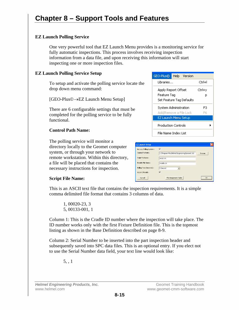
Chapter 8 – Support Tools and Features
Helmel Engineering Products, Inc. Geomet Training Handbookwww.helmel.com www.geomet-cmm-software.com
8-15
EZ Launch Polling Service
One very powerful tool that EZ Launch Menu provides is a monitoring service forfully automatic inspections. This process involves receiving inspectioninformation from a data file, and upon receiving this information will startinspecting one or more inspection files.
EZ Launch Polling Service Setup
To setup and activate the polling service locate thedrop down menu command:
[GEO-Plus©→EZ Launch Menu Setup]
There are 6 configurable settings that must becompleted for the polling service to be fullyfunctional.
Control Path Name:
The polling service will monitor adirectory locally to the Geomet computersystem, or through your network toremote workstation. Within this directory,a file will be placed that contains thenecessary instructions for inspection.
Script File Name:
This is an ASCII text file that contains the inspection requirements. It is a simplecomma delimited file format that contains 3 columns of data.
1, 00020-23, 35, 00133-001, 1
Column 1: This is the Cradle ID number where the inspection will take place. TheID number works only with the first Fixture Definition file. This is the topmostlisting as shown in the Base Definition described on page 8-9.
Column 2: Serial Number to be inserted into the part inspection header andsubsequently saved into SPC data files. This is an optional entry. If you elect notto use the Serial Number data field, your text line would look like:
5, , 1
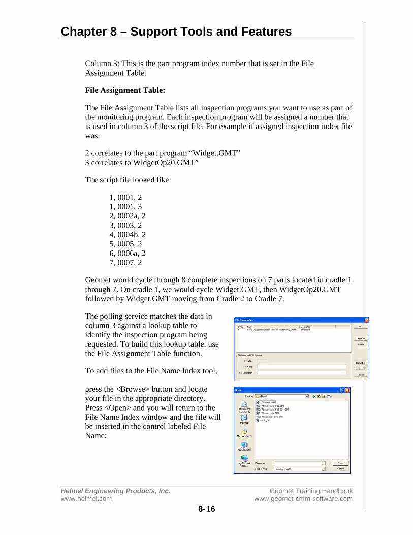
Chapter 8 – Support Tools and Features
Helmel Engineering Products, Inc. Geomet Training Handbookwww.helmel.com www.geomet-cmm-software.com
8-16
Column 3: This is the part program index number that is set in the FileAssignment Table.
File Assignment Table:
The File Assignment Table lists all inspection programs you want to use as part ofthe monitoring program. Each inspection program will be assigned a number thatis used in column 3 of the script file. For example if assigned inspection index filewas:
2 correlates to the part program “Widget.GMT”3 correlates to WidgetOp20.GMT”
The script file looked like:
1, 0001, 21, 0001, 32, 0002a, 23, 0003, 24, 0004b, 25, 0005, 26, 0006a, 27, 0007, 2
Geomet would cycle through 8 complete inspections on 7 parts located in cradle 1through 7. On cradle 1, we would cycle Widget.GMT, then WidgetOp20.GMTfollowed by Widget.GMT moving from Cradle 2 to Cradle 7.
The polling service matches the data incolumn 3 against a lookup table toidentify the inspection program beingrequested. To build this lookup table, usethe File Assignment Table function.
To add files to the File Name Index tool,
press the <Browse> button and locateyour file in the appropriate directory.Press <Open> and you will return to theFile Name Index window and the file willbe inserted in the control labeled FileName:
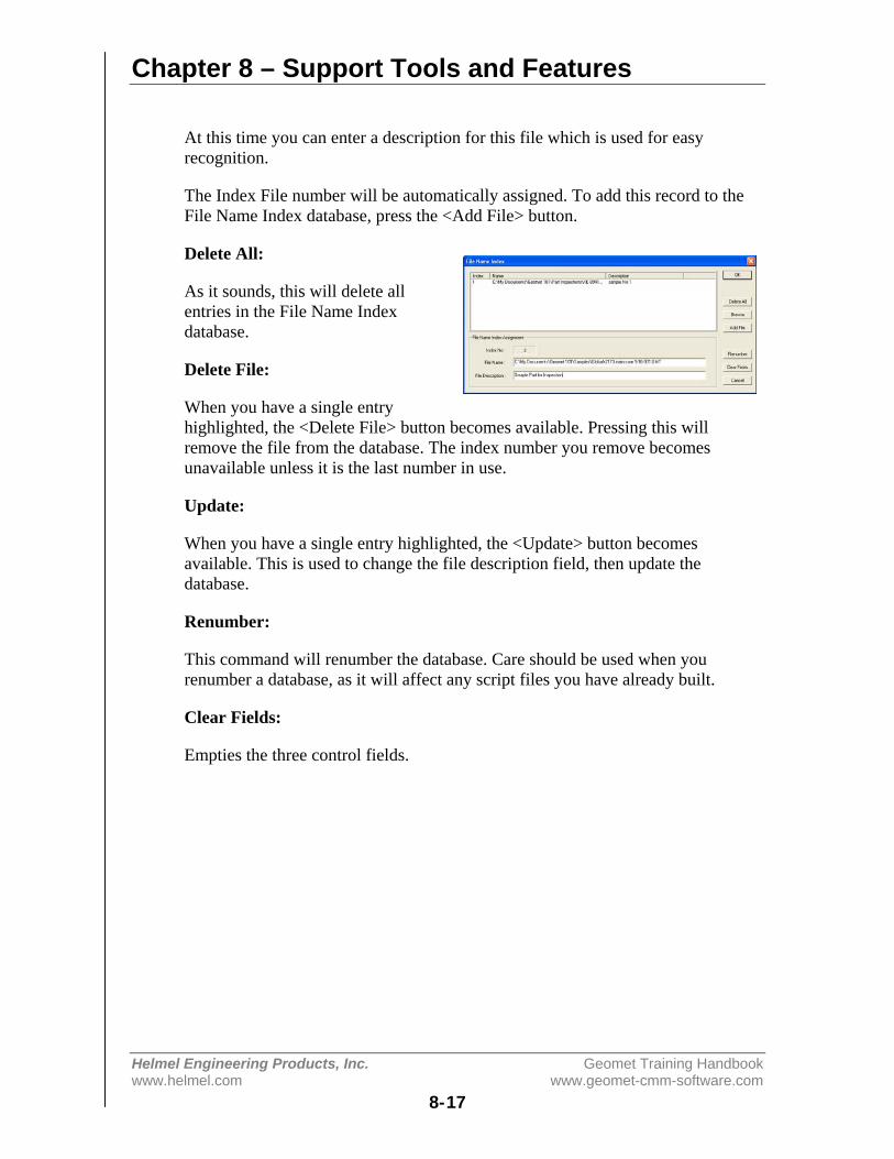
Chapter 8 – Support Tools and Features
Helmel Engineering Products, Inc. Geomet Training Handbookwww.helmel.com www.geomet-cmm-software.com
8-17
At this time you can enter a description for this file which is used for easyrecognition.
The Index File number will be automatically assigned. To add this record to theFile Name Index database, press the <Add File> button.
Delete All:
As it sounds, this will delete allentries in the File Name Indexdatabase.
Delete File:
When you have a single entryhighlighted, the <Delete File> button becomes available. Pressing this willremove the file from the database. The index number you remove becomesunavailable unless it is the last number in use.
Update:
When you have a single entry highlighted, the <Update> button becomesavailable. This is used to change the file description field, then update thedatabase.
Renumber:
This command will renumber the database. Care should be used when yourenumber a database, as it will affect any script files you have already built.
Clear Fields:
Empties the three control fields.
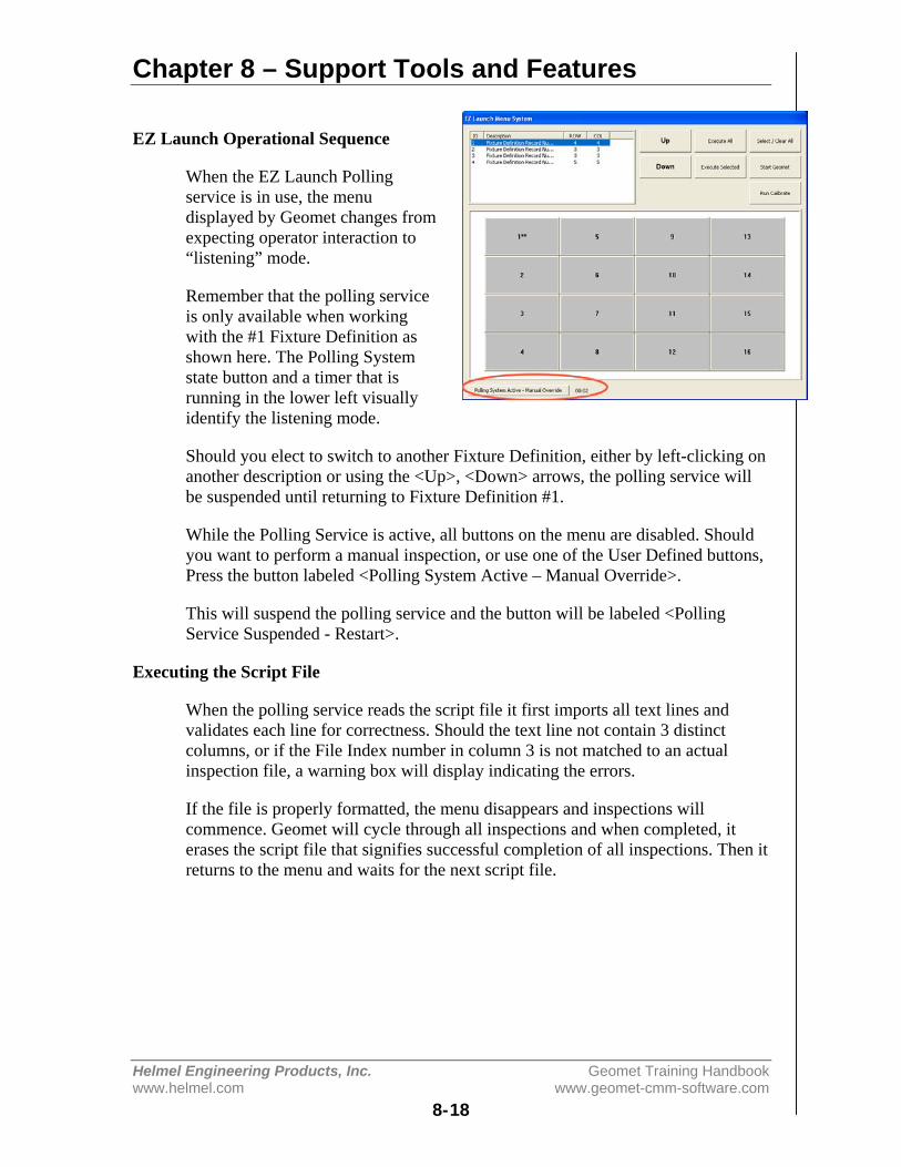
Chapter 8 – Support Tools and Features
Helmel Engineering Products, Inc. Geomet Training Handbookwww.helmel.com www.geomet-cmm-software.com
8-18
EZ Launch Operational Sequence
When the EZ Launch Pollingservice is in use, the menudisplayed by Geomet changes fromexpecting operator interaction to“listening” mode.
Remember that the polling serviceis only available when workingwith the #1 Fixture Definition asshown here. The Polling Systemstate button and a timer that isrunning in the lower left visuallyidentify the listening mode.
Should you elect to switch to another Fixture Definition, either by left-clicking onanother description or using the <Up>, <Down> arrows, the polling service willbe suspended until returning to Fixture Definition #1.
While the Polling Service is active, all buttons on the menu are disabled. Shouldyou want to perform a manual inspection, or use one of the User Defined buttons,Press the button labeled <Polling System Active – Manual Override>.
This will suspend the polling service and the button will be labeled <PollingService Suspended - Restart>.
Executing the Script File
When the polling service reads the script file it first imports all text lines andvalidates each line for correctness. Should the text line not contain 3 distinctcolumns, or if the File Index number in column 3 is not matched to an actualinspection file, a warning box will display indicating the errors.
If the file is properly formatted, the menu disappears and inspections willcommence. Geomet will cycle through all inspections and when completed, iterases the script file that signifies successful completion of all inspections. Then itreturns to the menu and waits for the next script file.

Chapter 8 – Support Tools and Features
Helmel Engineering Products, Inc. Geomet Training Handbookwww.helmel.com www.geomet-cmm-software.com
8-19
Feature Selection Tool
Feature Selection Tool provides expanded capabilities to Geomet through the useof random feature selections. Geomet has been developed over the years as asequential part-programming tool. This means that operation normally take placeon the last sequence of features. For example if you want to obtain the distancebetween two coplanar circles, press the distance key assuming the two circleswere the last two features in the report stack. If they are not, then recall the circlesto ensure they are the last two features in the report.
Feature Selection allows you to select these features anywhere in the report andperform the distance function. From the Feature Selection dialog, you canperform the following:
• Distances• Intersections• Angles• Bisects• Fit Lines, Circles, Planes, Cylinders• Fit Cylinder from Circles• Basic Math Calculations• Edit Tolerance Values in Groups
To activate the Feature Selector anytimeduring your inspection process, press the< ~ >, key on your keyboard. You can alsohighlight features in your inspection report andthrough the right-click submenu, choose[Feature Selection Tool].
How the feature selection tool displays features is dependent on whether featureswere highlighted before starting the tool. If no features were highlighted, then thetool will display all features in your report. Should you have previouslyhighlighted some features, then only those features will appear in the tool.
The tool is designed to provide you with a list of the current inspection. This listcan be sorted in many ways to assist in easier selection of features.
Using PCS Filters
There are several filters you can use in conjunction with viewing the features. Thefirst filter applies to Coordinate Systems. By default, the feature selection willshow all features regardless of PCS affiliation. If you want to choose a specificPCS, use the drop down box to choose an existing PCS. There is a button labeled<Current PCS> which will take you directly to the current PCS of the inspection
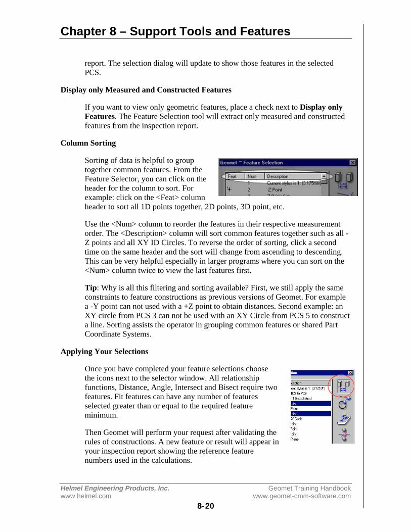
Chapter 8 – Support Tools and Features
Helmel Engineering Products, Inc. Geomet Training Handbookwww.helmel.com www.geomet-cmm-software.com
8-20
report. The selection dialog will update to show those features in the selectedPCS.
Display only Measured and Constructed Features
If you want to view only geometric features, place a check next to Display onlyFeatures. The Feature Selection tool will extract only measured and constructedfeatures from the inspection report.
Column Sorting
Sorting of data is helpful to grouptogether common features. From theFeature Selector, you can click on theheader for the column to sort. Forexample: click on the <Feat> columnheader to sort all 1D points together, 2D points, 3D point, etc.
Use the <Num> column to reorder the features in their respective measurementorder. The <Description> column will sort common features together such as all -Z points and all XY ID Circles. To reverse the order of sorting, click a secondtime on the same header and the sort will change from ascending to descending.This can be very helpful especially in larger programs where you can sort on the<Num> column twice to view the last features first.
Tip: Why is all this filtering and sorting available? First, we still apply the sameconstraints to feature constructions as previous versions of Geomet. For examplea -Y point can not used with a +Z point to obtain distances. Second example: anXY circle from PCS 3 can not be used with an XY Circle from PCS 5 to constructa line. Sorting assists the operator in grouping common features or shared PartCoordinate Systems.
Applying Your Selections
Once you have completed your feature selections choosethe icons next to the selector window. All relationshipfunctions, Distance, Angle, Intersect and Bisect require twofeatures. Fit features can have any number of featuresselected greater than or equal to the required featureminimum.
Then Geomet will perform your request after validating therules of constructions. A new feature or result will appear inyour inspection report showing the reference featurenumbers used in the calculations.
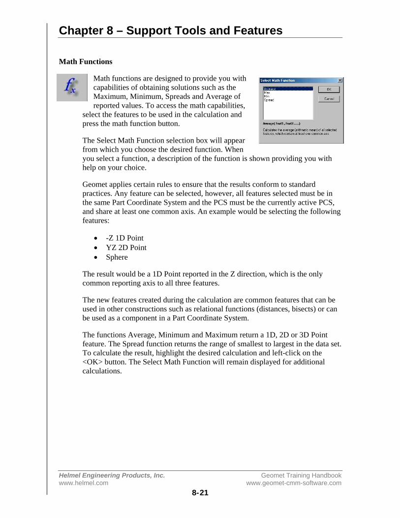
Chapter 8 – Support Tools and Features
Helmel Engineering Products, Inc. Geomet Training Handbookwww.helmel.com www.geomet-cmm-software.com
8-21
Math Functions
Math functions are designed to provide you withcapabilities of obtaining solutions such as theMaximum, Minimum, Spreads and Average ofreported values. To access the math capabilities,
select the features to be used in the calculation andpress the math function button.
The Select Math Function selection box will appearfrom which you choose the desired function. Whenyou select a function, a description of the function is shown providing you withhelp on your choice.
Geomet applies certain rules to ensure that the results conform to standardpractices. Any feature can be selected, however, all features selected must be inthe same Part Coordinate System and the PCS must be the currently active PCS,and share at least one common axis. An example would be selecting the followingfeatures:
• -Z 1D Point• YZ 2D Point• Sphere
The result would be a 1D Point reported in the Z direction, which is the onlycommon reporting axis to all three features.
The new features created during the calculation are common features that can beused in other constructions such as relational functions (distances, bisects) or canbe used as a component in a Part Coordinate System.
The functions Average, Minimum and Maximum return a 1D, 2D or 3D Pointfeature. The Spread function returns the range of smallest to largest in the data set.To calculate the result, highlight the desired calculation and left-click on the<OK> button. The Select Math Function will remain displayed for additionalcalculations.

Chapter 8 – Support Tools and Features
Helmel Engineering Products, Inc. Geomet Training Handbookwww.helmel.com www.geomet-cmm-software.com
8-22
Diameter Averaging using Math Functions
The Math Functions tool will review the highlightedfeatures in the Feature Selection Tool. Should allfeatures share a common type, example a Circle, theMath Functions will include "Diameter Averaging".
Diameter Averaging will take the diameters of allhighlighted features and record the following in theinspection report:
• Average Radius• Maximum Radius• Minimum Radius
Stylus Size Update using a Ring Gage
This math tool is designed to update the size of thecurrent qualified stylus based on previously measureRing Gages.
Under normal operations, the ball stylus is qualifiedagainst a known reference sphere. During thisqualification process the stylus size and location iscalculated. Under most conditions, the referencesphere qualification process is sufficient for all general inspection requirements.
However, measure a known ring gage and the measured diameter normally willbe different than the stated ring gage size. This happens due to variations in probedesign and usage. When qualifying against a reference sphere, the bottom of theprobe will trigger at a different pre-travel distance than a point taken at itsequator.
The Ring Gage Re-Qualification tool uses only readings around the equator tocalculate a high accuracy diameter of the stylus. The result will only update thesize of the stylus, not the 3D location. It is recommended that the Ring Gage bemeasured several times as separate records in your inspection report. The mathtool will then average all selected Ring Gage features for a more accuratesolution.
To start, active the stylus to be updated, see Choosing a Stylus, then follow thesesteps:

Chapter 8 – Support Tools and Features
Helmel Engineering Products, Inc. Geomet Training Handbookwww.helmel.com www.geomet-cmm-software.com
8-23
1. Create a Part Coordinate System on your Ring Gage.2. Measure the Ring Gage as an ID or IR Circle.3. Activate the Feature Selection Tool.4. Highlight the Ring Gage features.5. Select the Math button and from the choices select [Stylus Size Update].6. Enter the Ring Gage Radius when prompted.7. Geomet will report the change in stylus size and update the Stylus Manager.
NOTE: This process is designed for self teach operations only and will not createan inspection record that becomes part of an automated inspection.
DCC Option Menu
Through this drop down menu you willfind access to commands that disable orenable motion for selected features.
Use [Disable Motion] to set the flag for allthe current selected features. This instructsGeomet that when running a partinspection program to drop into manual CMM mode for the disabled features.Geomet will resume DCC operations after the last disabled flag.
The [Clear all Disable Motion] command will remove all disable flags in theentire part program. Additional information on disabling DCC motion can befound in the Chapter 9 – Working with Motion Control.
NOTE: There are conditions that prevent a feature from being successfully ranunder DCC. An example would be a small diameter where the positionaltolerance is sufficiently large to interfere with the motion map. By disabling themotion for that feature, the inspection program would drop into manual, orjoystick mode allowing the operator to measure the feature by hand. When thefeature is completed, DCC operations would resume.
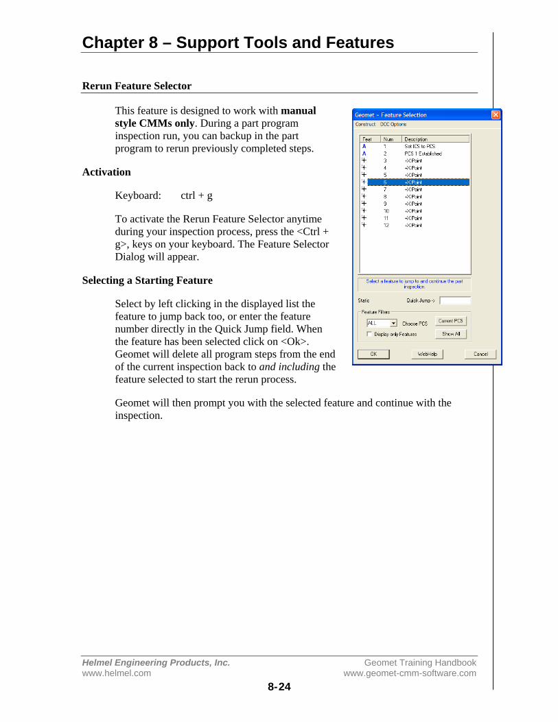
Chapter 8 – Support Tools and Features
Helmel Engineering Products, Inc. Geomet Training Handbookwww.helmel.com www.geomet-cmm-software.com
8-24
Rerun Feature Selector
This feature is designed to work with manualstyle CMMs only. During a part programinspection run, you can backup in the partprogram to rerun previously completed steps.
Activation
Keyboard: ctrl + g
To activate the Rerun Feature Selector anytimeduring your inspection process, press the <Ctrl +g>, keys on your keyboard. The Feature SelectorDialog will appear.
Selecting a Starting Feature
Select by left clicking in the displayed list thefeature to jump back too, or enter the featurenumber directly in the Quick Jump field. Whenthe feature has been selected click on <Ok>.Geomet will delete all program steps from the endof the current inspection back to and including thefeature selected to start the rerun process.
Geomet will then prompt you with the selected feature and continue with theinspection.
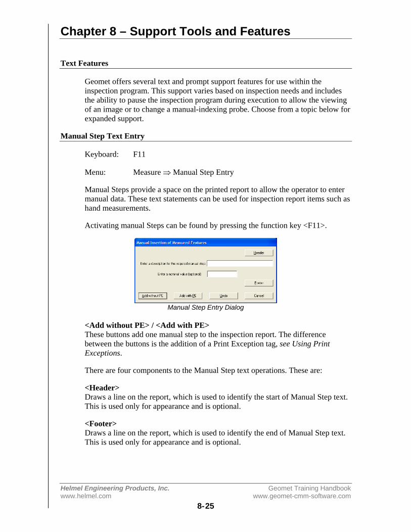
Chapter 8 – Support Tools and Features
Helmel Engineering Products, Inc. Geomet Training Handbookwww.helmel.com www.geomet-cmm-software.com
8-25
Text Features
Geomet offers several text and prompt support features for use within theinspection program. This support varies based on inspection needs and includesthe ability to pause the inspection program during execution to allow the viewingof an image or to change a manual-indexing probe. Choose from a topic below forexpanded support.
Manual Step Text Entry
Keyboard: F11
Menu: Measure ⇒ Manual Step Entry
Manual Steps provide a space on the printed report to allow the operator to entermanual data. These text statements can be used for inspection report items such ashand measurements.
Activating manual Steps can be found by pressing the function key <F11>.
Manual Step Entry Dialog
<Add without PE> / <Add with PE>These buttons add one manual step to the inspection report. The differencebetween the buttons is the addition of a Print Exception tag, see Using PrintExceptions.
There are four components to the Manual Step text operations. These are:
<Header>Draws a line on the report, which is used to identify the start of Manual Step text.This is used only for appearance and is optional.
<Footer>Draws a line on the report, which is used to identify the end of Manual Step text.This is used only for appearance and is optional.

Chapter 8 – Support Tools and Features
Helmel Engineering Products, Inc. Geomet Training Handbookwww.helmel.com www.geomet-cmm-software.com
8-26
Enter a DescriptionThe description field is used to enter a small note associated with the data to berecorded.
Nominal ValueThis is a value entered at the self teach stage which represents the target of themeasurement. An example involves the manual measurement of a boss using a 3-point micrometer; the operator would compare to the nominal reading of 1.000.This number is recorded as a text line in the report followed by an underlinedspace where the operator could then enter the actual reading manually. TheNominal Value entry is optional.
Manual Step Sample Output
In the output sample shown above, line 44 represents a Header, line 47 is thefooter. Line 45 shows an example where no nominal value is provided. Line 46shows and example where a Nominal Value has been entered.
During the part inspection run, Geomet will place this text on the report. It is thenthe responsibility of the operator to complete the inspection step by manuallyentering the Actual value measured.
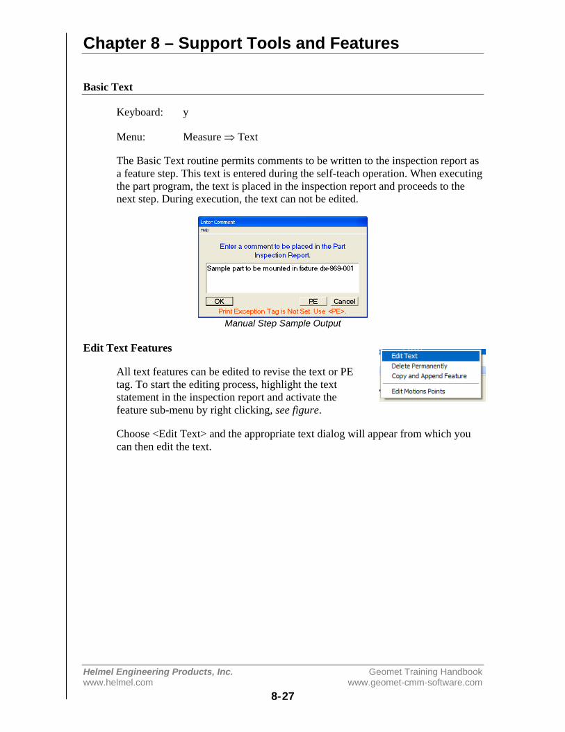
Chapter 8 – Support Tools and Features
Helmel Engineering Products, Inc. Geomet Training Handbookwww.helmel.com www.geomet-cmm-software.com
8-27
Basic Text
Keyboard: y
Menu: Measure ⇒ Text
The Basic Text routine permits comments to be written to the inspection report asa feature step. This text is entered during the self-teach operation. When executingthe part program, the text is placed in the inspection report and proceeds to thenext step. During execution, the text can not be edited.
Manual Step Sample Output
Edit Text Features
All text features can be edited to revise the text or PEtag. To start the editing process, highlight the textstatement in the inspection report and activate thefeature sub-menu by right clicking, see figure.
Choose <Edit Text> and the appropriate text dialog will appear from which youcan then edit the text.
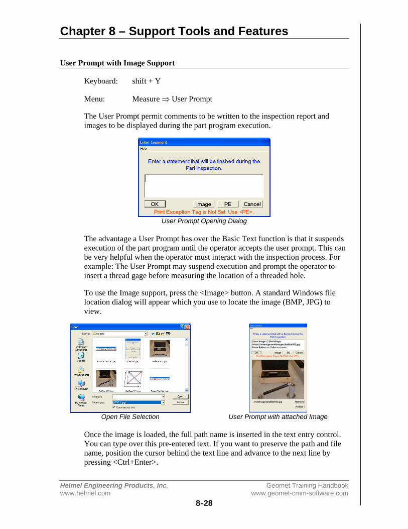
Chapter 8 – Support Tools and Features
Helmel Engineering Products, Inc. Geomet Training Handbookwww.helmel.com www.geomet-cmm-software.com
8-28
User Prompt with Image Support
Keyboard: shift + Y
Menu: Measure ⇒ User Prompt
The User Prompt permit comments to be written to the inspection report andimages to be displayed during the part program execution.
User Prompt Opening Dialog
The advantage a User Prompt has over the Basic Text function is that it suspendsexecution of the part program until the operator accepts the user prompt. This canbe very helpful when the operator must interact with the inspection process. Forexample: The User Prompt may suspend execution and prompt the operator toinsert a thread gage before measuring the location of a threaded hole.
To use the Image support, press the <Image> button. A standard Windows filelocation dialog will appear which you use to locate the image (BMP, JPG) toview.
Open File Selection User Prompt with attached Image
Once the image is loaded, the full path name is inserted in the text entry control.You can type over this pre-entered text. If you want to preserve the path and filename, position the cursor behind the text line and advance to the next line bypressing <Ctrl+Enter>.

Chapter 8 – Support Tools and Features
Helmel Engineering Products, Inc. Geomet Training Handbookwww.helmel.com www.geomet-cmm-software.com
8-29
Images that are larger than the available area in the dialog box will automaticallybe reduced to fit. Images that are smaller are displayed in their actual size. The<ReSize> button will stretch smaller images to fit the available area. Geometmaintains a link to the actual image file, therefore the image file should not bemoved from its original location on the hard drive.
When the inspection program is run, execution will pause when the User Promptis encountered. Execution will resume when the operator presses the <Ok>button.
In-Line Text Entry
Keyboard: alt + Y
In-Line Text Entry allows the user to suspend execution of a part program andenter text. The behavior of the In-Line text feature is similar to the User Prompt(without image support). When the pause in program execution occurs, theoperator then has an opportunity to enter new text. This text becomes part of thefinal inspection report.
Enter instructions for In-Line Text During run time.
In the examples above, the image on the left is the setup dialog for In-Line text.Here the programmer would enter instructions, which at run time, will instruct theoperator to add comments responding to the request.
The image on the right is what the operator would see. Only upon completion,will the inspection continue to the next step.
Text entry made in the final inspection report.

Chapter 8 – Support Tools and Features
Helmel Engineering Products, Inc. Geomet Training Handbookwww.helmel.com www.geomet-cmm-software.com
8-30
Edit Text Features
All text features can be edited to revise the text, and ifapplicable, the attached image. To start the editingprocess, highlight the text statement in the inspectionreport and activate the feature sub-menu by right clicking with your mouse. Ifonly one feature is highlighted, the edit text dialog will appear. If more than onefeature is highlighted, the sub-menu does not provide access to editing the textfeature.
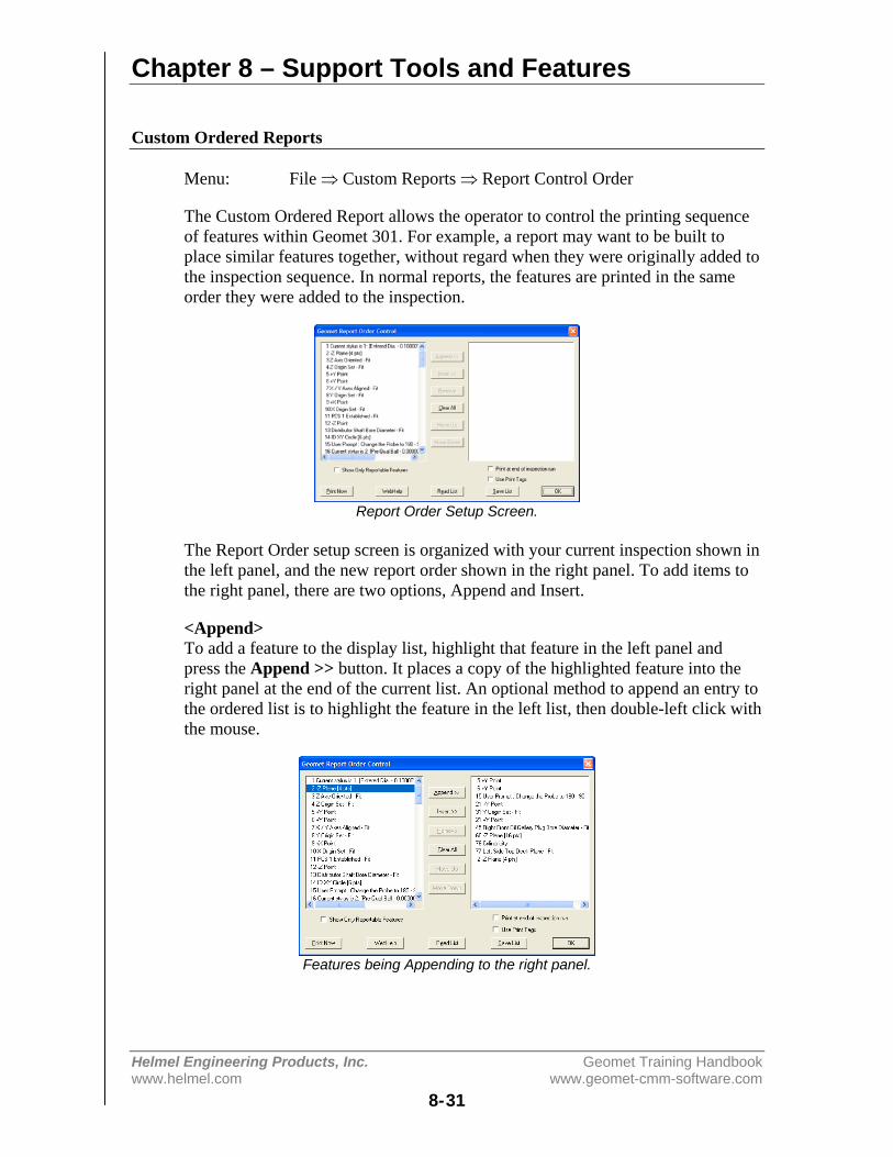
Chapter 8 – Support Tools and Features
Helmel Engineering Products, Inc. Geomet Training Handbookwww.helmel.com www.geomet-cmm-software.com
8-31
Custom Ordered Reports
Menu: File ⇒ Custom Reports ⇒ Report Control Order
The Custom Ordered Report allows the operator to control the printing sequenceof features within Geomet 301. For example, a report may want to be built toplace similar features together, without regard when they were originally added tothe inspection sequence. In normal reports, the features are printed in the sameorder they were added to the inspection.
Report Order Setup Screen.
The Report Order setup screen is organized with your current inspection shown inthe left panel, and the new report order shown in the right panel. To add items tothe right panel, there are two options, Append and Insert.
<Append>To add a feature to the display list, highlight that feature in the left panel andpress the Append >> button. It places a copy of the highlighted feature into theright panel at the end of the current list. An optional method to append an entry tothe ordered list is to highlight the feature in the left list, then double-left click withthe mouse.
Features being Appending to the right panel.
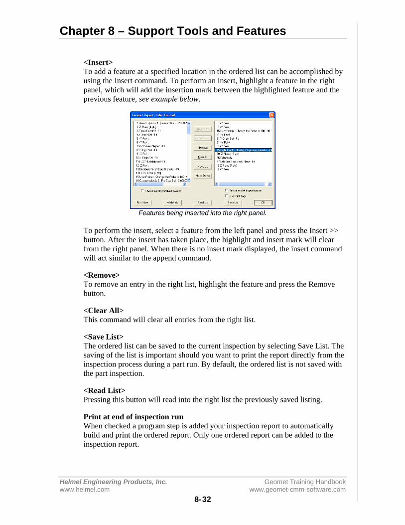
Chapter 8 – Support Tools and Features
Helmel Engineering Products, Inc. Geomet Training Handbookwww.helmel.com www.geomet-cmm-software.com
8-32
<Insert>To add a feature at a specified location in the ordered list can be accomplished byusing the Insert command. To perform an insert, highlight a feature in the rightpanel, which will add the insertion mark between the highlighted feature and theprevious feature, see example below.
Features being Inserted into the right panel.
To perform the insert, select a feature from the left panel and press the Insert >>button. After the insert has taken place, the highlight and insert mark will clearfrom the right panel. When there is no insert mark displayed, the insert commandwill act similar to the append command.
<Remove>To remove an entry in the right list, highlight the feature and press the Removebutton.
<Clear All>This command will clear all entries from the right list.
<Save List>The ordered list can be saved to the current inspection by selecting Save List. Thesaving of the list is important should you want to print the report directly from theinspection process during a part run. By default, the ordered list is not saved withthe part inspection.
<Read List>Pressing this button will read into the right list the previously saved listing.
Print at end of inspection runWhen checked a program step is added your inspection report to automaticallybuild and print the ordered report. Only one ordered report can be added to theinspection report.
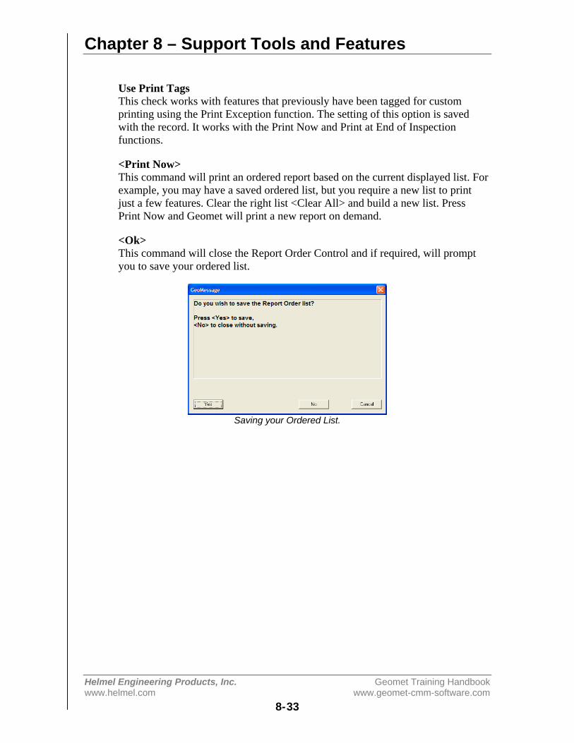
Chapter 8 – Support Tools and Features
Helmel Engineering Products, Inc. Geomet Training Handbookwww.helmel.com www.geomet-cmm-software.com
8-33
Use Print TagsThis check works with features that previously have been tagged for customprinting using the Print Exception function. The setting of this option is savedwith the record. It works with the Print Now and Print at End of Inspectionfunctions.
<Print Now>This command will print an ordered report based on the current displayed list. Forexample, you may have a saved ordered list, but you require a new list to printjust a few features. Clear the right list <Clear All> and build a new list. PressPrint Now and Geomet will print a new report on demand.
<Ok>This command will close the Report Order Control and if required, will promptyou to save your ordered list.
Saving your Ordered List.
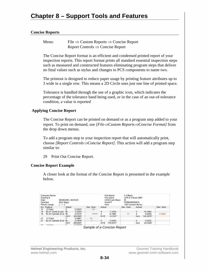
Chapter 8 – Support Tools and Features
Helmel Engineering Products, Inc. Geomet Training Handbookwww.helmel.com www.geomet-cmm-software.com
8-34
Concise Reports
Menu: File ⇒ Custom Reports ⇒ Concise ReportReport Controls ⇒ Concise Report
The Concise Report format is an efficient and condensed printed report of yourinspection reports. This report format prints all standard essential inspection stepssuch as measured and constructed features eliminating program steps that deliverno final values such as stylus and changes to PCS components to name two.
The printout is designed to reduce paper usage by printing feature attributes up to3 wide in a single row. This means a 2D Circle uses just one line of printed space.
Tolerance is handled through the use of a graphic icon, which indicates thepercentage of the tolerance band being used, or in the case of an out-of-tolerancecondition, a value is reported
Applying Concise Report
The Concise Report can be printed on demand or as a program step added to yourreport. To print on demand, use [File⇒Custom Reports⇒Concise Format] fromthe drop down menus.
To add a program step to your inspection report that will automatically print,choose [Report Controls⇒Concise Report]. This action will add a program stepsimilar to:
29 Print Out Concise Report.
Concise Report Example
A closer look at the format of the Concise Report is presented in the examplebelow.
Sample of a Concise Report
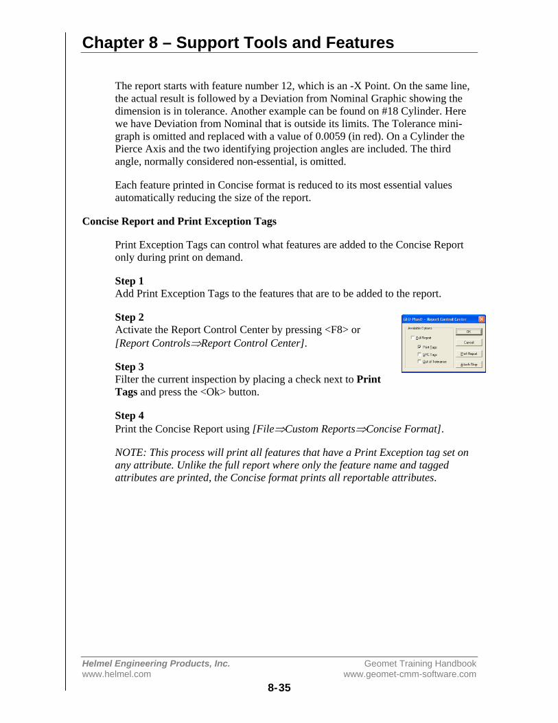
Chapter 8 – Support Tools and Features
Helmel Engineering Products, Inc. Geomet Training Handbookwww.helmel.com www.geomet-cmm-software.com
8-35
The report starts with feature number 12, which is an -X Point. On the same line,the actual result is followed by a Deviation from Nominal Graphic showing thedimension is in tolerance. Another example can be found on #18 Cylinder. Herewe have Deviation from Nominal that is outside its limits. The Tolerance mini-graph is omitted and replaced with a value of 0.0059 (in red). On a Cylinder thePierce Axis and the two identifying projection angles are included. The thirdangle, normally considered non-essential, is omitted.
Each feature printed in Concise format is reduced to its most essential valuesautomatically reducing the size of the report.
Concise Report and Print Exception Tags
Print Exception Tags can control what features are added to the Concise Reportonly during print on demand.
Step 1Add Print Exception Tags to the features that are to be added to the report.
Step 2Activate the Report Control Center by pressing <F8> or[Report Controls⇒Report Control Center].
Step 3Filter the current inspection by placing a check next to PrintTags and press the <Ok> button.
Step 4Print the Concise Report using [File⇒Custom Reports⇒Concise Format].
NOTE: This process will print all features that have a Print Exception tag set onany attribute. Unlike the full report where only the feature name and taggedattributes are printed, the Concise format prints all reportable attributes.

Chapter 8 – Support Tools and Features
Helmel Engineering Products, Inc. Geomet Training Handbookwww.helmel.com www.geomet-cmm-software.com
8-36
Report Control Center
Keyboard: F8
Menu: Report Controls ⇒ Report Control Center
The Report Control Center performs two main operations. The first is manualcontrol to print reports using the standard print format, but controlling whetherPrint Exception, SPC Tags or Out-of-Tolerance conditions are set. The secondfunction is to add an automatic Print feature to the inspection report.
On Demand Printing
Activate the Report Control Center from the drop-down menu [ReportControls⇒Report Control Center], when or press the function button <F8>.
To control the displayed and printed report, place a check next to the reportoption.
Report Control Center
To view or print only features that have been tagged under Print Exception, placea check next to Print Tags. To combine tags, you can place multiple checksagainst an option.
Program Action Step
Configure your report by placing checks on the options to be included in theprinted report. Press the <Attach Step> button and an action feature will be addedto the inspection report. This new feature will automatically print the configuredreport at the designated place in the inspection run.

Chapter 8 – Support Tools and Features
Helmel Engineering Products, Inc. Geomet Training Handbookwww.helmel.com www.geomet-cmm-software.com
8-37
Print Exception / SPC Tags
Keyboard: p
Menu: GeoPlus ⇒ Feature Tag
Feature Attribute Tags provide tools to customize printouts, assign featurecharacteristics for ASCII exporting and build GeoStat database records. The mostcommon use for Tags is to produce inspection reports that contain only the featurevalues you require.
Applying Feature Attribute Tags
The Feature Tag dialog provides the necessary tools to assign attribute tags. Toactivate Feature Tags, highlight the feature in the inspection report and right-clickto activate the feature sub-menu. Choose [Feature Tag]. Optionally you may usethe keystroke <p> or menu options.
Feature Tag Control Panel Right Click Activation
The Feature Tag dialog will appear configured to the highlighted feature. Withinthe dialog, there are three columns of check boxes that are defined as:
PE: Print Exceptions. When a check is placed against an attribute, the ReportControl Center will add that feature and attribute to the printed inspection report.Only tagged features will be printed allowing control over the printing process.The symbol " • " is placed next to the attribute in the full displayed inspectionreport indicating it has been tagged.
SPC: ASCII Export Control. When a check is placed against an attribute, Geometwill export this attribute to an ASCII text file. The exporting process is automaticduring an inspection run, or can be done manually through the drop-down menuselection [File⇒Export⇒Export ASCII SPC Data] The symbol " § " is placednext to the attribute in the full displayed inspection report indicating it has beentagged for SPC exporting. The configuration of the exporting formats iscontrolled in the System Option, SPC Format page <F9> or [System⇒SystemOptions].
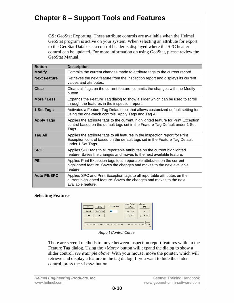
Chapter 8 – Support Tools and Features
Helmel Engineering Products, Inc. Geomet Training Handbookwww.helmel.com www.geomet-cmm-software.com
8-38
GS: GeoStat Exporting. These attribute controls are available when the HelmelGeoStat program is active on your system. When selecting an attribute for exportto the GeoStat Database, a control header is displayed where the SPC headercontrol can be updated. For more information on using GeoStat, please review theGeoStat Manual.
Button DescriptionModify Commits the current changes made to attribute tags to the current record.Next Feature Retrieves the next feature from the inspection report and displays its current
values and attributes.Clear Clears all flags on the current feature, commits the changes with the Modify
button.More / Less Expands the Feature Tag dialog to show a slider which can be used to scroll
through the features in the inspection report.1 Set Tags Activates a Feature Tag Default tool that allows customized default setting for
using the one-touch controls, Apply Tags and Tag All.Apply Tags Applies the attribute tags to the current, highlighted feature for Print Exception
control based on the default tags set in the Feature Tag Default under 1 SetTags.
Tag All Applies the attribute tags to all features in the inspection report for PrintException control based on the default tags set in the Feature Tag Defaultunder 1 Set Tags.
SPC Applies SPC tags to all reportable attributes on the current highlightedfeature. Saves the changes and moves to the next available feature.
PE Applies Print Exception tags to all reportable attributes on the currenthighlighted feature. Saves the changes and moves to the next availablefeature.
Auto PE/SPC Applies SPC and Print Exception tags to all reportable attributes on thecurrent highlighted feature. Saves the changes and moves to the nextavailable feature.
Selecting Features
Report Control Center
There are several methods to move between inspection report features while in theFeature Tag dialog. Using the <More> button will expand the dialog to show aslider control, see example above. With your mouse, move the pointer, which willretrieve and display a feature in the tag dialog. If you want to hide the slidercontrol, press the <Less> button.
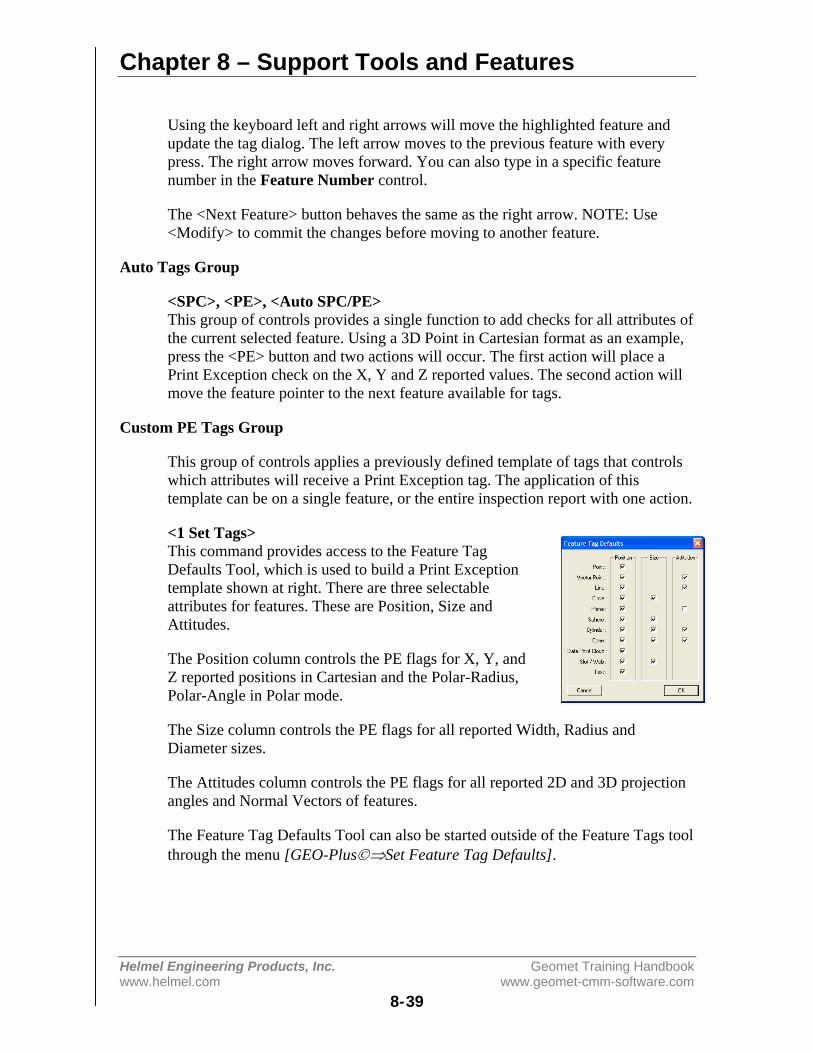
Chapter 8 – Support Tools and Features
Helmel Engineering Products, Inc. Geomet Training Handbookwww.helmel.com www.geomet-cmm-software.com
8-39
Using the keyboard left and right arrows will move the highlighted feature andupdate the tag dialog. The left arrow moves to the previous feature with everypress. The right arrow moves forward. You can also type in a specific featurenumber in the Feature Number control.
The <Next Feature> button behaves the same as the right arrow. NOTE: Use<Modify> to commit the changes before moving to another feature.
Auto Tags Group
<SPC>, <PE>, <Auto SPC/PE>This group of controls provides a single function to add checks for all attributes ofthe current selected feature. Using a 3D Point in Cartesian format as an example,press the <PE> button and two actions will occur. The first action will place aPrint Exception check on the X, Y and Z reported values. The second action willmove the feature pointer to the next feature available for tags.
Custom PE Tags Group
This group of controls applies a previously defined template of tags that controlswhich attributes will receive a Print Exception tag. The application of thistemplate can be on a single feature, or the entire inspection report with one action.
<1 Set Tags>This command provides access to the Feature TagDefaults Tool, which is used to build a Print Exceptiontemplate shown at right. There are three selectableattributes for features. These are Position, Size andAttitudes.
The Position column controls the PE flags for X, Y, andZ reported positions in Cartesian and the Polar-Radius,Polar-Angle in Polar mode.
The Size column controls the PE flags for all reported Width, Radius andDiameter sizes.
The Attitudes column controls the PE flags for all reported 2D and 3D projectionangles and Normal Vectors of features.
The Feature Tag Defaults Tool can also be started outside of the Feature Tags toolthrough the menu [GEO-Plus©⇒Set Feature Tag Defaults].
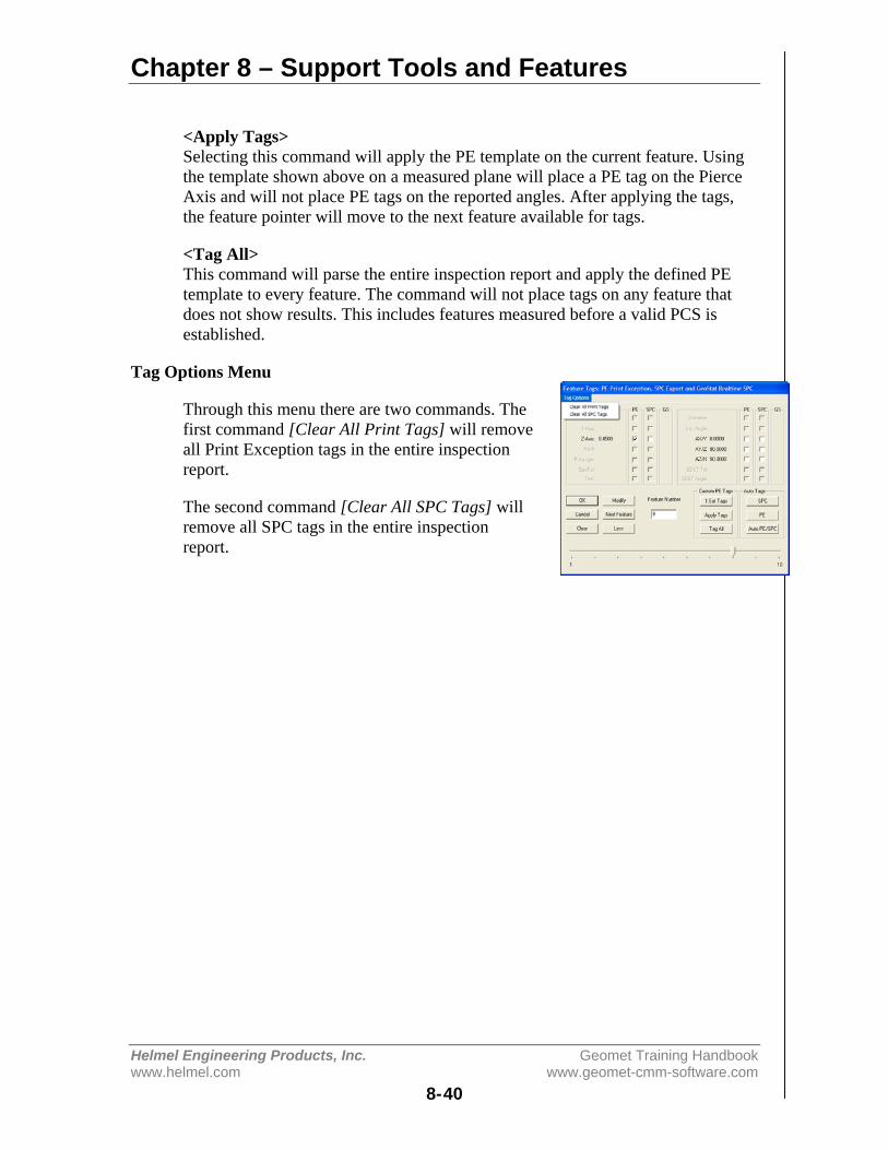
Chapter 8 – Support Tools and Features
Helmel Engineering Products, Inc. Geomet Training Handbookwww.helmel.com www.geomet-cmm-software.com
8-40
<Apply Tags>Selecting this command will apply the PE template on the current feature. Usingthe template shown above on a measured plane will place a PE tag on the PierceAxis and will not place PE tags on the reported angles. After applying the tags,the feature pointer will move to the next feature available for tags.
<Tag All>This command will parse the entire inspection report and apply the defined PEtemplate to every feature. The command will not place tags on any feature thatdoes not show results. This includes features measured before a valid PCS isestablished.
Tag Options Menu
Through this menu there are two commands. Thefirst command [Clear All Print Tags] will removeall Print Exception tags in the entire inspectionreport.
The second command [Clear All SPC Tags] willremove all SPC tags in the entire inspectionreport.

Chapter 8 – Support Tools and Features
Helmel Engineering Products, Inc. Geomet Training Handbookwww.helmel.com www.geomet-cmm-software.com
8-41
Report Offset
Keyboard: ctrl + y
Menu: GeoPlus ⇒ Apply Report Offset
The Report Offset Tool is used to apply a reference value to a reported attributeon any feature. One example is the rotation of an angle to match the drawing. Thisallows the printed inspection report to match the drawing. Using an example of a2D XY Circle, we will apply an offset to the angle.
ID XY Circle [16 pts]Cartesian Format Polar Format
ID= 0.5000” ID= 0.5000”X= 4.3300” Pol-R= 4.9999”Y= 2.5000” Angle= 30.0007°
Here we show the Cartesian and Polar formats for reference. The angle of30.0007° is referenced off the x-axis going counter clockwise. The drawingreferences the angle off the y-axis and has a nominal value of 60.0°. To make acorrection to the reported value, we can add a nominal offset value to the reportedangle.
Report Offset Tool
As shown in the Report Offset Tool, we entered a –90 in the Pol Angle: control.The result to the reported angle is shown to the right.
ID XY Circle [16 pts]Before After
ID= 0.5000” ID= 0.5000”Pol-R= 4.9999” Pol-R= 4.9999”Angle= 30.0007° Angle= -59.9993°
The Report Offset can be applied to any feature and any reported position. It iscarried forward to inspection runs.
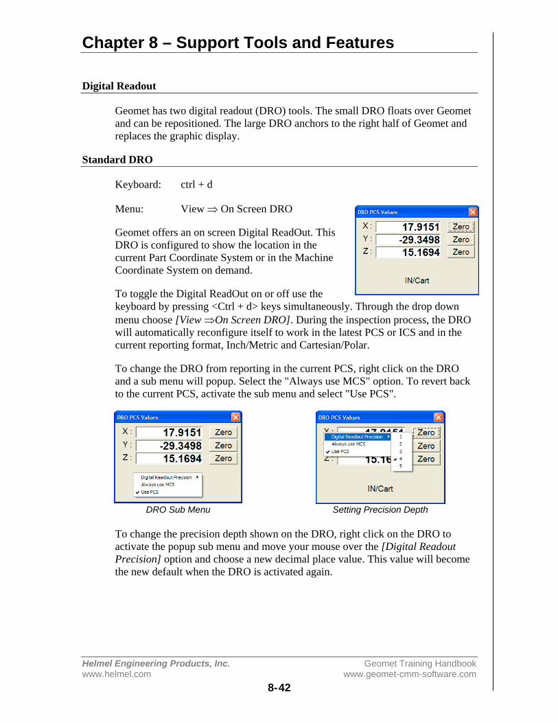
Chapter 8 – Support Tools and Features
Helmel Engineering Products, Inc. Geomet Training Handbookwww.helmel.com www.geomet-cmm-software.com
8-42
Digital Readout
Geomet has two digital readout (DRO) tools. The small DRO floats over Geometand can be repositioned. The large DRO anchors to the right half of Geomet andreplaces the graphic display.
Standard DRO
Keyboard: ctrl + d
Menu: View ⇒ On Screen DRO
Geomet offers an on screen Digital ReadOut. ThisDRO is configured to show the location in thecurrent Part Coordinate System or in the MachineCoordinate System on demand.
To toggle the Digital ReadOut on or off use thekeyboard by pressing <Ctrl + d> keys simultaneously. Through the drop downmenu choose [View ⇒On Screen DRO]. During the inspection process, the DROwill automatically reconfigure itself to work in the latest PCS or ICS and in thecurrent reporting format, Inch/Metric and Cartesian/Polar.
To change the DRO from reporting in the current PCS, right click on the DROand a sub menu will popup. Select the "Always use MCS" option. To revert backto the current PCS, activate the sub menu and select "Use PCS".
DRO Sub Menu Setting Precision Depth
To change the precision depth shown on the DRO, right click on the DRO toactivate the popup sub menu and move your mouse over the [Digital ReadoutPrecision] option and choose a new decimal place value. This value will becomethe new default when the DRO is activated again.
Chapter 8 – Support Tools and Features
Helmel Engineering Products, Inc. Geomet Training Handbookwww.helmel.com www.geomet-cmm-software.com
8-43
Relative Zero
To set a zero reference for any axis, toggle the button opposite the axis to control.On first selection, the axis will zero out. Select the button again, and the DRO willremove the zero reference and return to normal reporting.
Polar versus Cartesian Reporting
The DRO reports the location in reference to the current Part Coordinate System.Should Geomet be set to report in Polar mode, the DRO will show the radiallength and polar direction to the current origin.

Chapter 8 – Support Tools and Features
Helmel Engineering Products, Inc. Geomet Training Handbookwww.helmel.com www.geomet-cmm-software.com
8-44
Full DRO
To assist the visual appearance of a Digital ReadOut at greater distances, Geometoffers a large text Full DRO. The Full DRO position reporting defaults to theXYZ location in the current Part Coordinate System. However, due to its size, itreplaces the drawing on the right portion of the Geomet display.
Starting the Full DRO
Keyboard: shift + D
System Options: Enhance Features Page
The Full DRO is activated through the [System Options⇒Enhance Features]page by placing a check next to Enable Full DRO. Optionally you can use thekeyboard <Shift> + <D> keys.
Full DRO Placement
Using the Full DRO
Changing precision places and coordinate system assignments can customize theFull DRO. This is accomplished through the use of a sub menu activated whenright clicking on the Full DRO.
The Full DRO sub menu controls the visual state of the Feature Measurement,Editing, Constructions, PCS and Part Programming tool bars. Additional controlsinclude the setting of the display decimal place for both length and angularreporting.

Chapter 8 – Support Tools and Features
Helmel Engineering Products, Inc. Geomet Training Handbookwww.helmel.com www.geomet-cmm-software.com
8-45
Relative Zero
To set a zero reference for any axis, toggle the button opposite the axis to control.On first selection, the axis will zero out. Select the button again, and the DRO willremove the zero reference and return to normal reporting.
Vector Point Targeting
The Full DRO displays the targeting position when performing a manual vectorpoint. The normal vector point targeting display offers smaller digital text size,which has limited use on larger CMMs. The Full DRO will provide the targetingposition and because of its larger text size, allows efficient use even on largeCMMs.

Chapter 8 – Support Tools and Features
Helmel Engineering Products, Inc. Geomet Training Handbookwww.helmel.com www.geomet-cmm-software.com
8-46
In-Line Math Calculator
Geomet offers an In-Line Math calculator on supported Dialog Boxes. Thisallows solving of simple math formulas when the operator enters data.
When a supported dialog box appears that has In-Line Math functionality it willbe identified by having a small calculator icon next to the supported control, seefigure below. Not all dialog boxes support the In-Line Math Calculator.
DRO Sub Menu Setting Precision Depth
When you see this icon, the edit control directly to the left will offer simple mathsolving function. To use, begin by entering your formula in the edit control. Forexample enter "2.0" in the edit control, as shown above. Next we press theaddition key “+” and Geomet recognizes a math function is being requested anddisplays a small calculator. NOTE: The In-Line Math Calculator will activatewhen pressing one of the following:
• Plus <+>• Minus <->• Multiply <*>• Divide </>
The initial value of "2.0" is passed into the calculator and the math symbol "+" isdisplayed to the left of the lower edit control. Enter in the number to be added tothe upper number and press any of the math keys, " + - * / or =" which will solvethe current operation and transfer the new value into the upper display awaitinganother calculation.
To return the solution to the originating data field, press <Enter>.
Metric / Inch Conversion
The current value displayed in the upper display will be converted into metric(mm) or inches by pressing the corresponding button. The In-Line mathCalculator makes no assignment to the values as they are calculated. By pressingthe <mm> button, the upper value will be multiplied by 25.4 and when pressing<inch>, the upper values are divided by 25.4.

Chapter 8 – Support Tools and Features
Helmel Engineering Products, Inc. Geomet Training Handbookwww.helmel.com www.geomet-cmm-software.com
8-47
Complete Table of In-Line Math functions:
Description+ (Plus) Solves the function X + Y and returns the result in X.- (Minus) Solves the function X - Y and returns the result in X.* (Multiply) Solves the function X * Y and returns the result in X./ (Divide) Solves the function X / Y and returns the result in X.
= (Equal) Solves the current operation and transfers the result back to the Xposition. This does not close the Calculator.
mm Converts the upper value (X) by multiplying it by 25.4.inch Converts the upper value (X) by dividing it by 25.4.Sqrt Converts the upper value (X) by determining its square root.-/+ Changes the sign of the lower value (Y).MC Clears any value stored in memory.MR Recalls the value stored in memory in the lower value (Y).MS Replace any value in memory with the upper value (X).M+ Add the upper value (X) to the current value in memory.C Clear X and Y, does not clear memory.
CE Clear the current lower value (Y).
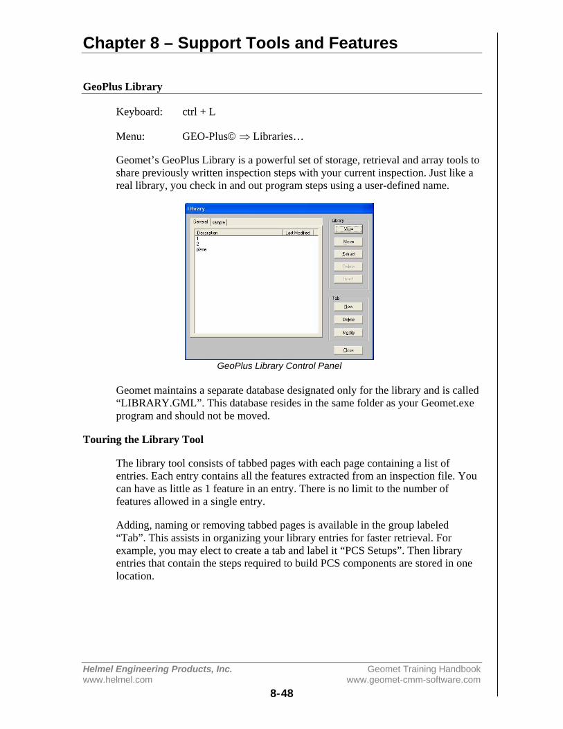
Chapter 8 – Support Tools and Features
Helmel Engineering Products, Inc. Geomet Training Handbookwww.helmel.com www.geomet-cmm-software.com
8-48
GeoPlus Library
Keyboard: ctrl + L
Menu: GEO-Plus© ⇒ Libraries…
Geomet’s GeoPlus Library is a powerful set of storage, retrieval and array tools toshare previously written inspection steps with your current inspection. Just like areal library, you check in and out program steps using a user-defined name.
GeoPlus Library Control Panel
Geomet maintains a separate database designated only for the library and is called“LIBRARY.GML”. This database resides in the same folder as your Geomet.exeprogram and should not be moved.
Touring the Library Tool
The library tool consists of tabbed pages with each page containing a list ofentries. Each entry contains all the features extracted from an inspection file. Youcan have as little as 1 feature in an entry. There is no limit to the number offeatures allowed in a single entry.
Adding, naming or removing tabbed pages is available in the group labeled“Tab”. This assists in organizing your library entries for faster retrieval. Forexample, you may elect to create a tab and label it “PCS Setups”. Then libraryentries that contain the steps required to build PCS components are stored in onelocation.
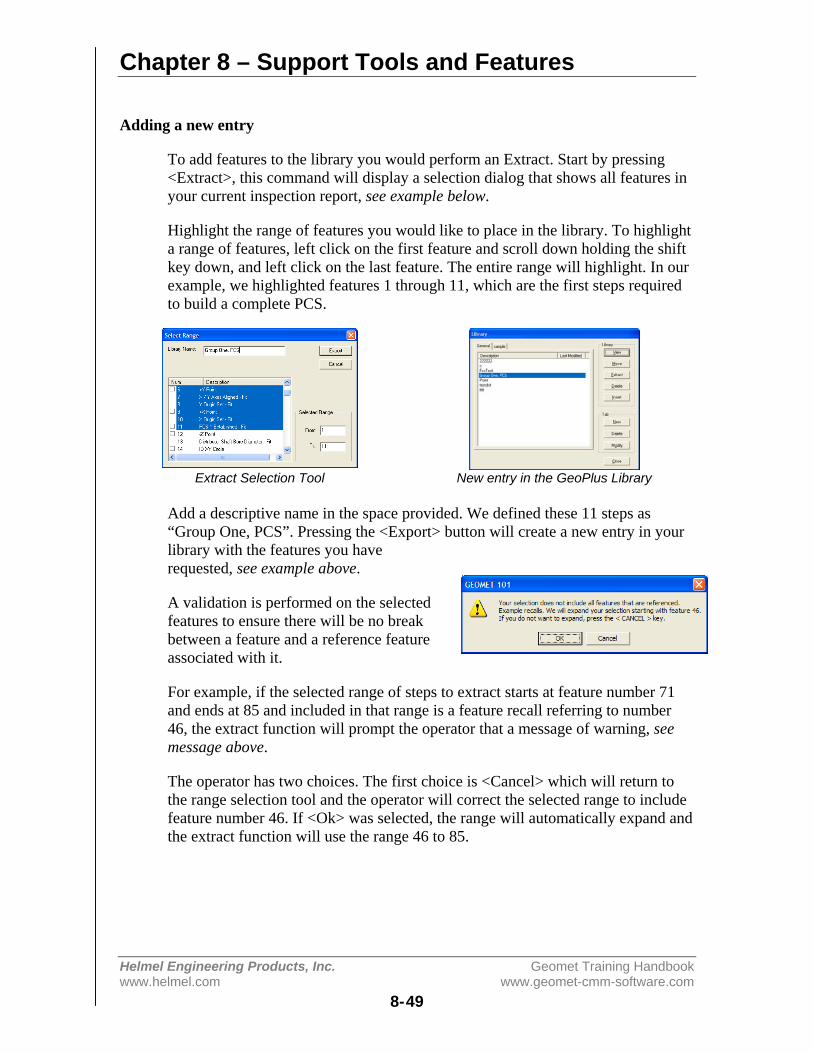
Chapter 8 – Support Tools and Features
Helmel Engineering Products, Inc. Geomet Training Handbookwww.helmel.com www.geomet-cmm-software.com
8-49
Adding a new entry
To add features to the library you would perform an Extract. Start by pressing<Extract>, this command will display a selection dialog that shows all features inyour current inspection report, see example below.
Highlight the range of features you would like to place in the library. To highlighta range of features, left click on the first feature and scroll down holding the shiftkey down, and left click on the last feature. The entire range will highlight. In ourexample, we highlighted features 1 through 11, which are the first steps requiredto build a complete PCS.
Extract Selection Tool New entry in the GeoPlus Library
Add a descriptive name in the space provided. We defined these 11 steps as“Group One, PCS”. Pressing the <Export> button will create a new entry in yourlibrary with the features you haverequested, see example above.
A validation is performed on the selectedfeatures to ensure there will be no breakbetween a feature and a reference featureassociated with it.
For example, if the selected range of steps to extract starts at feature number 71and ends at 85 and included in that range is a feature recall referring to number46, the extract function will prompt the operator that a message of warning, seemessage above.
The operator has two choices. The first choice is <Cancel> which will return tothe range selection tool and the operator will correct the selected range to includefeature number 46. If <Ok> was selected, the range will automatically expand andthe extract function will use the range 46 to 85.
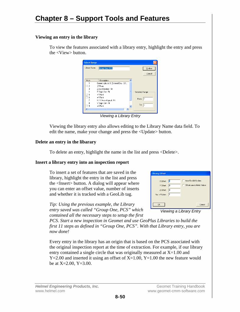
Chapter 8 – Support Tools and Features
Helmel Engineering Products, Inc. Geomet Training Handbookwww.helmel.com www.geomet-cmm-software.com
8-50
Viewing an entry in the library
To view the features associated with a library entry, highlight the entry and pressthe <View> button.
Viewing a Library Entry
Viewing the library entry also allows editing to the Library Name data field. Toedit the name, make your change and press the <Update> button.
Delete an entry in the libarary
To delete an entry, highlight the name in the list and press <Delete>.
Insert a library entry into an inspection report
To insert a set of features that are saved in thelibrary, highlight the entry in the list and pressthe <Insert> button. A dialog will appear whereyou can enter an offset value, number of insertsand whether it is tracked with a GeoLib tag.
Tip: Using the previous example, the Libraryentry saved was called “Group One, PCS” whichcontained all the necessary steps to setup the firstPCS. Start a new inspection in Geomet and use GeoPlus Libraries to build thefirst 11 steps as defined in “Group One, PCS”. With that Library entry, you arenow done!
Every entry in the library has an origin that is based on the PCS associated withthe original inspection report at the time of extraction. For example, if our libraryentry contained a single circle that was originally measured at X=1.00 andY=2.00 and inserted it using an offset of X=1.00, Y=1.00 the new feature wouldbe at X=2.00, Y=3.00.
Viewing a Library Entry

Chapter 8 – Support Tools and Features
Helmel Engineering Products, Inc. Geomet Training Handbookwww.helmel.com www.geomet-cmm-software.com
8-51
The ability to insert many features with a repetitive pattern can be accomplishedby entering a number greater than 1 in the data field “No. in Pattern”. During theinsertion process, the offset value is applied, and incremented with each entry.
For example, if you require to measure a row of –Z points consisting of 25 pointsincremented 0.500” between points, you would enter 25 in the “No. in Pattern”field and 0.500” in the X data field.
Then when the <Ok> button is pressed, 25 new –Z data points would be created.Each point would be updated, not only for its new position, but any associatedmotion and tolerance nominal data would also be recalculated.
Auto GeoLib Update
During an insert operation you can add a tracking flag to the inserted features.This is called a GeoLib tag. A flag and time/date stamp of the library entry will beadded to the inspection report receiving the new features. There will be additionalnew features added, one at the beginning of the new feature set, and one at theend.
The feature numbers will be enclosed in brackets such as [120], which indicates itis a “locked” group of features. No changes such as inserting, deleting or movingof this group of features will be allowed.
Each time the file is opened, a test is made against the GeoPlus Library to ensurethe library entry has not been changed. If the library entry has been updated, suchas a revision change, the open file process will ask if the new entry should beinserted. This allows you the flexibility to insert inspection steps, such as insertsthat you know are subject to part revision changes.
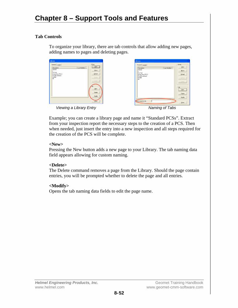
Chapter 8 – Support Tools and Features
Helmel Engineering Products, Inc. Geomet Training Handbookwww.helmel.com www.geomet-cmm-software.com
8-52
Tab Controls
To organize your library, there are tab controls that allow adding new pages,adding names to pages and deleting pages.
Viewing a Library Entry Naming of Tabs
Example; you can create a library page and name it “Standard PCSs”. Extractfrom your inspection report the necessary steps to the creation of a PCS. Thenwhen needed, just insert the entry into a new inspection and all steps required forthe creation of the PCS will be complete.
<New>Pressing the New button adds a new page to your Library. The tab naming datafield appears allowing for custom naming.
<Delete>The Delete command removes a page from the Library. Should the page containentries, you will be prompted whether to delete the page and all entries.
<Modify>Opens the tab naming data fields to edit the page name.
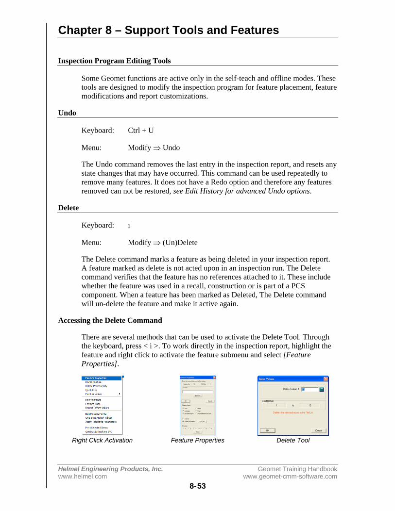
Chapter 8 – Support Tools and Features
Helmel Engineering Products, Inc. Geomet Training Handbookwww.helmel.com www.geomet-cmm-software.com
8-53
Inspection Program Editing Tools
Some Geomet functions are active only in the self-teach and offline modes. Thesetools are designed to modify the inspection program for feature placement, featuremodifications and report customizations.
Undo
Keyboard: Ctrl + U
Menu: Modify ⇒ Undo
The Undo command removes the last entry in the inspection report, and resets anystate changes that may have occurred. This command can be used repeatedly toremove many features. It does not have a Redo option and therefore any featuresremoved can not be restored, see Edit History for advanced Undo options.
Delete
Keyboard: i
Menu: Modify ⇒ (Un)Delete
The Delete command marks a feature as being deleted in your inspection report.A feature marked as delete is not acted upon in an inspection run. The Deletecommand verifies that the feature has no references attached to it. These includewhether the feature was used in a recall, construction or is part of a PCScomponent. When a feature has been marked as Deleted, The Delete commandwill un-delete the feature and make it active again.
Accessing the Delete Command
There are several methods that can be used to activate the Delete Tool. Throughthe keyboard, press < i >. To work directly in the inspection report, highlight thefeature and right click to activate the feature submenu and select [FeatureProperties].
Right Click Activation Feature Properties Delete Tool

Chapter 8 – Support Tools and Features
Helmel Engineering Products, Inc. Geomet Training Handbookwww.helmel.com www.geomet-cmm-software.com
8-54
Deleting a Feature
To delete a feature, activate the Delete tool. Enter a Feature Number that specifiesthe feature to be deleted. Press the <Ok> button and the feature will be changed inthe inspection report and marked as deleted.
If you are deleting the feature through the Feature Properties tool, place a checknext to “Deleted”.
Un-Deleting a Feature
To un-delete a feature, activate the Delete Mode. Enter a Feature Number thatspecifies the feature to be un-deleted. Press the <Ok> button and the feature willbe changed in the inspection report back to its original state.
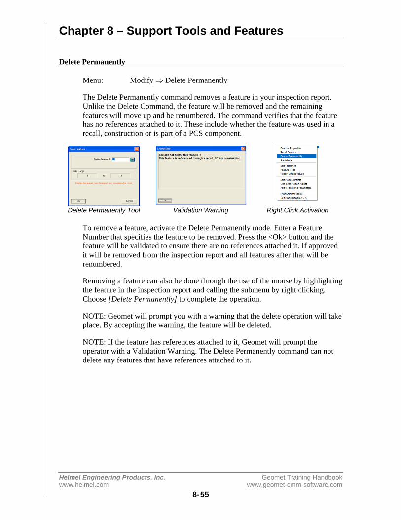
Chapter 8 – Support Tools and Features
Helmel Engineering Products, Inc. Geomet Training Handbookwww.helmel.com www.geomet-cmm-software.com
8-55
Delete Permanently
Menu: Modify ⇒ Delete Permanently
The Delete Permanently command removes a feature in your inspection report.Unlike the Delete Command, the feature will be removed and the remainingfeatures will move up and be renumbered. The command verifies that the featurehas no references attached to it. These include whether the feature was used in arecall, construction or is part of a PCS component.
Delete Permanently Tool Validation Warning Right Click Activation
To remove a feature, activate the Delete Permanently mode. Enter a FeatureNumber that specifies the feature to be removed. Press the <Ok> button and thefeature will be validated to ensure there are no references attached it. If approvedit will be removed from the inspection report and all features after that will berenumbered.
Removing a feature can also be done through the use of the mouse by highlightingthe feature in the inspection report and calling the submenu by right clicking.Choose [Delete Permanently] to complete the operation.
NOTE: Geomet will prompt you with a warning that the delete operation will takeplace. By accepting the warning, the feature will be deleted.
NOTE: If the feature has references attached to it, Geomet will prompt theoperator with a Validation Warning. The Delete Permanently command can notdelete any features that have references attached to it.

Chapter 8 – Support Tools and Features
Helmel Engineering Products, Inc. Geomet Training Handbookwww.helmel.com www.geomet-cmm-software.com
8-56
Delete All After
Menu: Modify ⇒ Delete All Records After…
The Delete all Records After... command prompts for a feature number that willbecome the last feature in the report. All features after that position will bedeleted.
Deleting Features from a Starting Point
To delete all features after a specified featurenumber, activate the Delete All After Mode. Entera Feature Number, which specifies the last featureto keep, and all features after this number will bedeleted. Press the <Ok> button and the inspectionreport will update to reflect the command.
Tip: If you highlight your feature in the inspectionreport then activate the Delete All After tool, thefeature number will transfer into the dialog automatically.
NOTE: When this command has been executed, the features are permanentlyremoved. Only through the use of the Advanced Edit History Tool can they beretrieved.
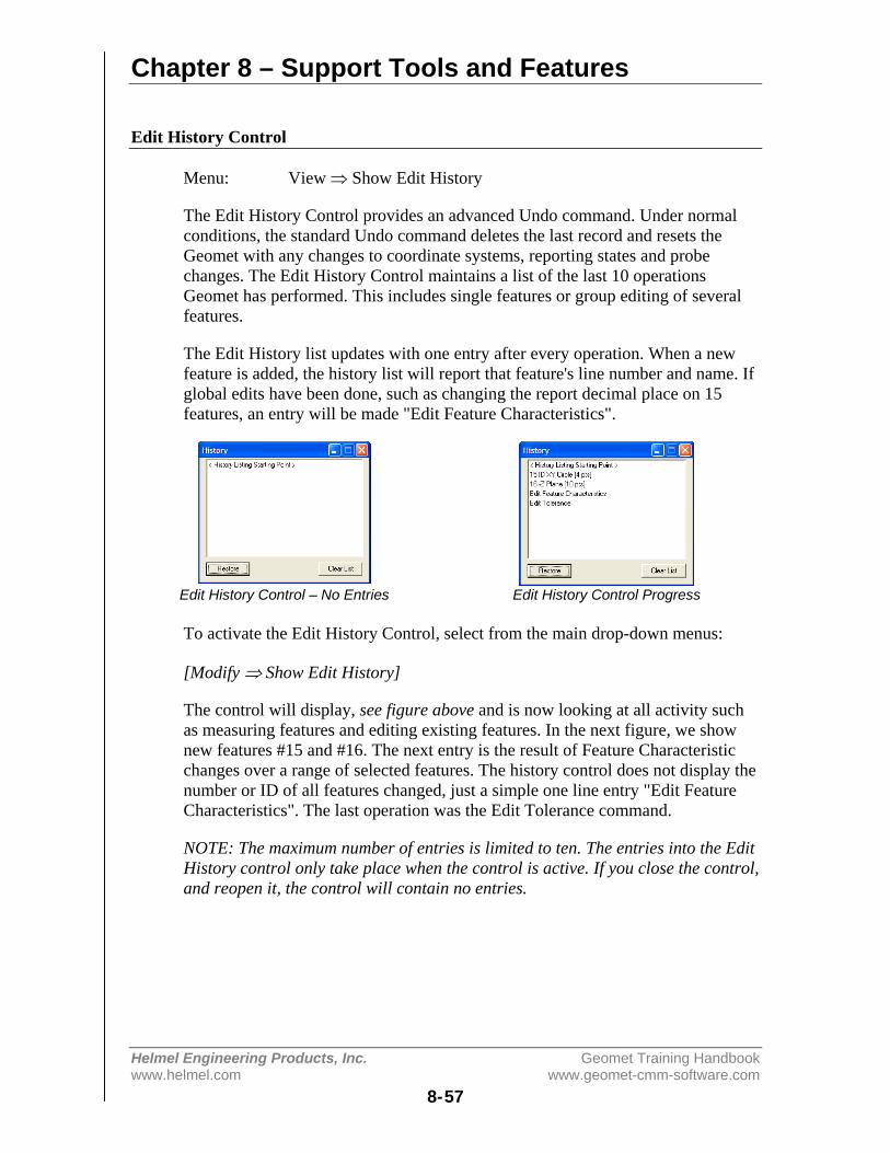
Chapter 8 – Support Tools and Features
Helmel Engineering Products, Inc. Geomet Training Handbookwww.helmel.com www.geomet-cmm-software.com
8-57
Edit History Control
Menu: View ⇒ Show Edit History
The Edit History Control provides an advanced Undo command. Under normalconditions, the standard Undo command deletes the last record and resets theGeomet with any changes to coordinate systems, reporting states and probechanges. The Edit History Control maintains a list of the last 10 operationsGeomet has performed. This includes single features or group editing of severalfeatures.
The Edit History list updates with one entry after every operation. When a newfeature is added, the history list will report that feature's line number and name. Ifglobal edits have been done, such as changing the report decimal place on 15features, an entry will be made "Edit Feature Characteristics".
Edit History Control – No Entries Edit History Control Progress
To activate the Edit History Control, select from the main drop-down menus:
[Modify ⇒ Show Edit History]
The control will display, see figure above and is now looking at all activity suchas measuring features and editing existing features. In the next figure, we shownew features #15 and #16. The next entry is the result of Feature Characteristicchanges over a range of selected features. The history control does not display thenumber or ID of all features changed, just a simple one line entry "Edit FeatureCharacteristics". The last operation was the Edit Tolerance command.
NOTE: The maximum number of entries is limited to ten. The entries into the EditHistory control only take place when the control is active. If you close the control,and reopen it, the control will contain no entries.

Chapter 8 – Support Tools and Features
Helmel Engineering Products, Inc. Geomet Training Handbookwww.helmel.com www.geomet-cmm-software.com
8-58
Using Advanced Undo
The Edit History control can Undo up to the last 10 operations. In our example,we need to Undo the last two operations. To accomplish this, select the historyrecord you want the Undo command to work back towards. This selected recordwill be the last record in your inspection report after you press the <Restore>button.
Selecting a feature for the Undo Command Undo Command completed
After the restore is completed, the Edit History Tool will show the results of theRestore command. You selected record, #16 –Z Plane, is now the last entry in theEdit History Tool and in your inspection report.
<Clear List>The Clear List button will remove all exiting entries in the Edit History control.
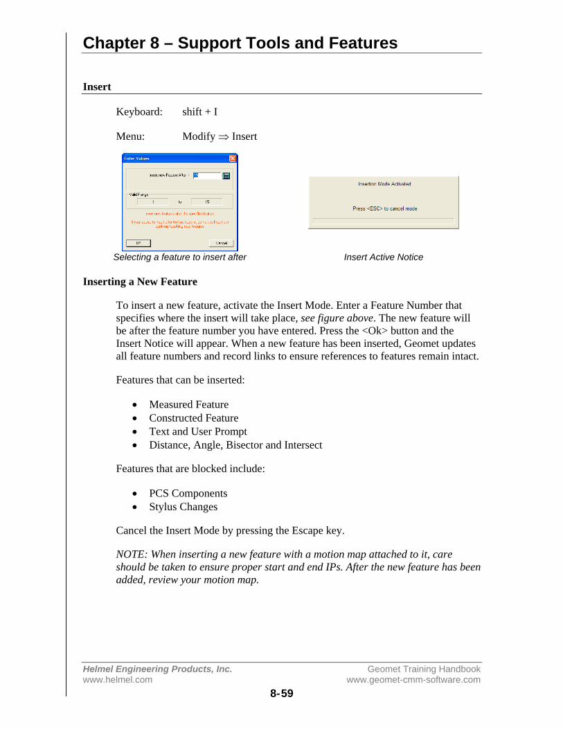
Chapter 8 – Support Tools and Features
Helmel Engineering Products, Inc. Geomet Training Handbookwww.helmel.com www.geomet-cmm-software.com
8-59
Insert
Keyboard: shift + I
Menu: Modify ⇒ Insert
Selecting a feature to insert after Insert Active Notice
Inserting a New Feature
To insert a new feature, activate the Insert Mode. Enter a Feature Number thatspecifies where the insert will take place, see figure above. The new feature willbe after the feature number you have entered. Press the <Ok> button and theInsert Notice will appear. When a new feature has been inserted, Geomet updatesall feature numbers and record links to ensure references to features remain intact.
Features that can be inserted:
• Measured Feature• Constructed Feature• Text and User Prompt• Distance, Angle, Bisector and Intersect
Features that are blocked include:
• PCS Components• Stylus Changes
Cancel the Insert Mode by pressing the Escape key.
NOTE: When inserting a new feature with a motion map attached to it, careshould be taken to ensure proper start and end IPs. After the new feature has beenadded, review your motion map.

Chapter 8 – Support Tools and Features
Helmel Engineering Products, Inc. Geomet Training Handbookwww.helmel.com www.geomet-cmm-software.com
8-60
Move
Keyboard: ctrl + i
Menu: Modify ⇒ Insert
The Move command allows the repositioning of a feature to another locationwithin the inspection program. Assurances are provided to prevent moving toanother PCS, or when the current probe is not the same as the feature's activeprobe.
Selecting a feature to move Select a new position
To move a feature, enter a number of the feature to be moved, see figure above.Press the <Ok> button then enter the location in the inspection report the featurewill be moved to. Press <Ok> and Geomet will validate your request and performthe move.
When the feature has been moved, Geomet renumbers all feature numbers andrecord links to ensure references to features remain intact.
TIP: Should you want to permanently delete a feature, such as feature number 15of a 50 step inspection program. Start by moving the feature to the end of theinspection report. Once this has been accomplished, Press <Ctrl + u> which isthe Undo command.
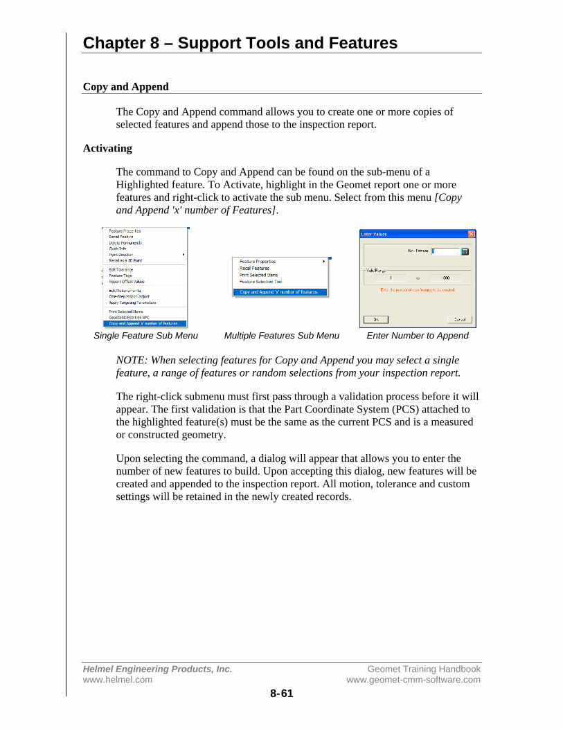
Chapter 8 – Support Tools and Features
Helmel Engineering Products, Inc. Geomet Training Handbookwww.helmel.com www.geomet-cmm-software.com
8-61
Copy and Append
The Copy and Append command allows you to create one or more copies ofselected features and append those to the inspection report.
Activating
The command to Copy and Append can be found on the sub-menu of aHighlighted feature. To Activate, highlight in the Geomet report one or morefeatures and right-click to activate the sub menu. Select from this menu [Copyand Append 'x' number of Features].
Single Feature Sub Menu Multiple Features Sub Menu Enter Number to Append
NOTE: When selecting features for Copy and Append you may select a singlefeature, a range of features or random selections from your inspection report.
The right-click submenu must first pass through a validation process before it willappear. The first validation is that the Part Coordinate System (PCS) attached tothe highlighted feature(s) must be the same as the current PCS and is a measuredor constructed geometry.
Upon selecting the command, a dialog will appear that allows you to enter thenumber of new features to build. Upon accepting this dialog, new features will becreated and appended to the inspection report. All motion, tolerance and customsettings will be retained in the newly created records.
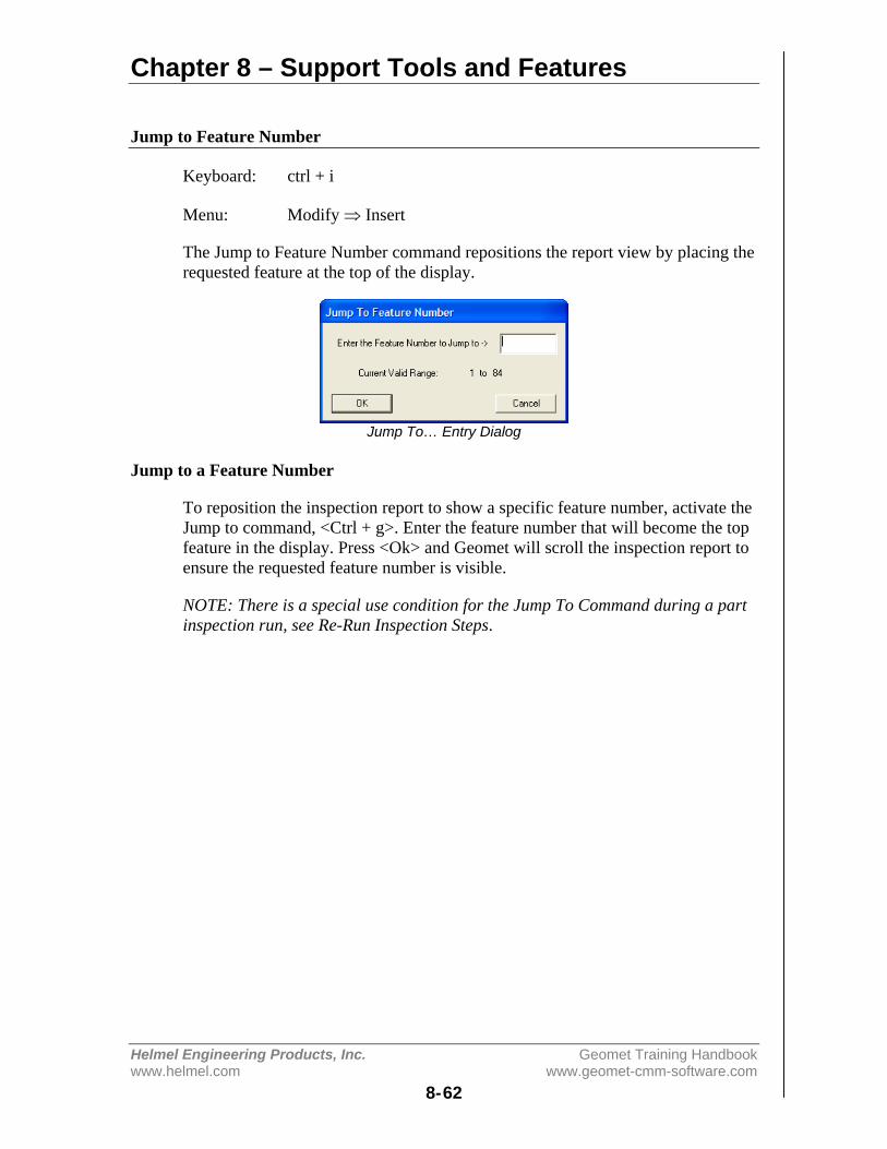
Chapter 8 – Support Tools and Features
Helmel Engineering Products, Inc. Geomet Training Handbookwww.helmel.com www.geomet-cmm-software.com
8-62
Jump to Feature Number
Keyboard: ctrl + i
Menu: Modify ⇒ Insert
The Jump to Feature Number command repositions the report view by placing therequested feature at the top of the display.
Jump To… Entry Dialog
Jump to a Feature Number
To reposition the inspection report to show a specific feature number, activate theJump to command, <Ctrl + g>. Enter the feature number that will become the topfeature in the display. Press <Ok> and Geomet will scroll the inspection report toensure the requested feature number is visible.
NOTE: There is a special use condition for the Jump To Command during a partinspection run, see Re-Run Inspection Steps.

Chapter 8 – Support Tools and Features
Helmel Engineering Products, Inc. Geomet Training Handbookwww.helmel.com www.geomet-cmm-software.com
8-63
Feature Properties
Feature Properties tools in Geomet allows the changing of states, access totolerance values and other feature specific information. To activate the tool,highlight one or more features and in the report area, right-click your mouse.
Single Feature Selection Submenu Multiple Feature Selection Submenu
Single Feature Selection Submenu
When only one feature has been selected in the inspection report, activating theFeature Properties tool provides an expanded set of commands, see left figureabove.
General Feature Commands Feature Specific Commands
The expanded Feature Properties tool is constructed with common commands, seeleft figure above, and feature specific commands, see right figure above. Thecommon tools are shared with all features. The feature specific commands changeto adapt to the selected feature.
In this example the selected feature is a 2D XY Circle and the CMM is a DCCstyle which instructs the Feature submenu generator to add motion tools.
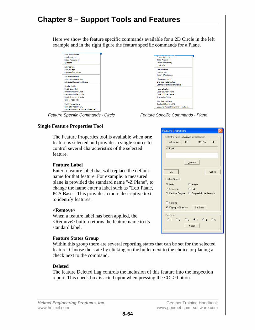
Chapter 8 – Support Tools and Features
Helmel Engineering Products, Inc. Geomet Training Handbookwww.helmel.com www.geomet-cmm-software.com
8-64
Here we show the feature specific commands available for a 2D Circle in the leftexample and in the right figure the feature specific commands for a Plane.
Feature Specific Commands - Circle Feature Specific Commands - Plane
Single Feature Properties Tool
The Feature Properties tool is available when onefeature is selected and provides a single source tocontrol several characteristics of the selectedfeature.
Feature LabelEnter a feature label that will replace the defaultname for that feature. For example: a measuredplane is provided the standard name "-Z Plane", tochange the name enter a label such as "Left Plane,PCS Base". This provides a more descriptive textto identify features.
<Remove>When a feature label has been applied, the<Remove> button returns the feature name to itsstandard label.
Feature States GroupWithin this group there are several reporting states that can be set for the selectedfeature. Choose the state by clicking on the bullet next to the choice or placing acheck next to the command.
DeletedThe feature Deleted flag controls the inclusion of this feature into the inspectionreport. This check box is acted upon when pressing the <Ok> button.
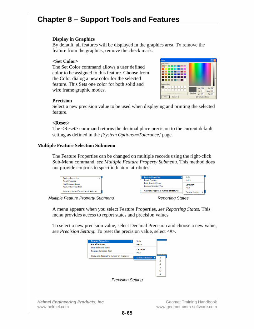
Chapter 8 – Support Tools and Features
Helmel Engineering Products, Inc. Geomet Training Handbookwww.helmel.com www.geomet-cmm-software.com
8-65
Display in GraphicsBy default, all features will be displayed in the graphics area. To remove thefeature from the graphics, remove the check mark.
<Set Color>The Set Color command allows a user definedcolor to be assigned to this feature. Choose fromthe Color dialog a new color for the selectedfeature. This Sets one color for both solid andwire frame graphic modes.
PrecisionSelect a new precision value to be used when displaying and printing the selectedfeature.
<Reset>The <Reset> command returns the decimal place precision to the current defaultsetting as defined in the [System Options⇒Tolerance] page.
Multiple Feature Selection Submenu
The Feature Properties can be changed on multiple records using the right-clickSub-Menu command, see Multiple Feature Property Submenu. This method doesnot provide controls to specific feature attributes.
Multiple Feature Property Submenu Reporting States
A menu appears when you select Feature Properties, see Reporting States. Thismenu provides access to report states and precision values.
To select a new precision value, select Decimal Precision and choose a new value,see Precision Setting. To reset the precision value, select <#>.
Precision Setting

Chapter 8 – Support Tools and Features
Helmel Engineering Products, Inc. Geomet Training Handbookwww.helmel.com www.geomet-cmm-software.com
8-66
Geomet will update all highlighted features with your requested changes.
NOTE: If the highlighted features are mixed reporting states or precision values,this command will over write all settings to the common choice being made.
[Recall Features]When the Recall Feature command is selected, each selected feature will generateits own programming step, or transaction file entry which is appended to theinspection report and will be operated on as a unique entity by other Geometfunctions. For example, if features 16, 25, 26 and 32 are highlighted in an 89-stepprogram, they will be appended as 90, 91, 92 and 93.
As in all Geomet functions, feature validations are applied to ensure crediblerecalls. These include ensuring the features being recalled are from the same PCSas the current PCS to name just one. Feature links will be updated to reflect anychanges.
[Print Selected Items]This command will generate a printed report consisting only of the highlightedfeatures. This is not a programmable step and is acted upon immediately.
[Feature Selection Tool]Activates the Feature Selection tool and populates the tool only with thehighlighted features. This is helpful when performing constructions using randomfeatures. For example we might highlight features 12, 15, 56, 57 which are 2Dpoints and construct a circle through them. Using this command the FeatureSelection tool will appear only with the four highlighted features. Within theFeature Selection tool, choose Fit Circle.

Chapter 8 – Support Tools and Features
Helmel Engineering Products, Inc. Geomet Training Handbookwww.helmel.com www.geomet-cmm-software.com
8-67
Report Navigation Keys
There are several key presses that compliment the standard Windows interface toscroll and reposition through the displayed inspection report. In Windows, a list,or report that exceeds the boundaries of the display will provide scroll barsnormally located on the right and bottom of the view. Using these scroll barsrequires the use of the mouse that controls the positioning by sliding the "ScrollBox". For further assistance on using scroll bars, please review Help in Windows.
Geomet provides shortcut key presses to control the positioning of the inspectionreport in the available area on the display.
Geomet Inspection Report Navigation KeysDown Arrow Moves the inspection report down one line.
Up Arrow Moves the inspection report up one line.Left Arrow Moves the Inspection report to the left one character.
Right Arrow Moves the Inspection report to the right one character.Home Scrolls the report to show the Header (focus required).
Ctrl + Home Scrolls the report to show the Header (focus not required).End Scrolls the report to show the last feature (focus required).
Ctrl + End Scrolls the report to show the last feature (focus required).Ctrl + g Jump to a specific feature number.
NOTE: Windows sends all key presses to the Window or Dialog that has "Focus",considered the current topmost active window. For example, if you have Geometand another program, such as Excel active, the program that has "Focus" willreceive all key presses. If you press the <Home> key when the inspection reportis not the current "Focused" control, no response is seen.
To illustrate, open a long inspection report and click your mouse in the graphicarea. Press <Home> or <End> and the inspection report does not move. That isbecause the graphic window has the current focus. Click your mouse in the reportarea and repeat the key presses and the report will scroll according to yourcommands.
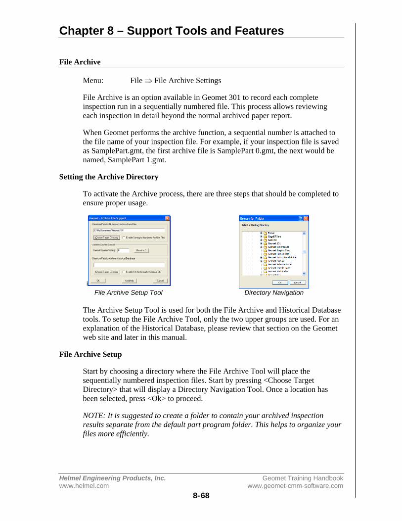
Chapter 8 – Support Tools and Features
Helmel Engineering Products, Inc. Geomet Training Handbookwww.helmel.com www.geomet-cmm-software.com
8-68
File Archive
Menu: File ⇒ File Archive Settings
File Archive is an option available in Geomet 301 to record each completeinspection run in a sequentially numbered file. This process allows reviewingeach inspection in detail beyond the normal archived paper report.
When Geomet performs the archive function, a sequential number is attached tothe file name of your inspection file. For example, if your inspection file is savedas SamplePart.gmt, the first archive file is SamplePart 0.gmt, the next would benamed, SamplePart 1.gmt.
Setting the Archive Directory
To activate the Archive process, there are three steps that should be completed toensure proper usage.
iFile Archive Setup Tool Directory Navigation
The Archive Setup Tool is used for both the File Archive and Historical Databasetools. To setup the File Archive Tool, only the two upper groups are used. For anexplanation of the Historical Database, please review that section on the Geometweb site and later in this manual.
File Archive Setup
Start by choosing a directory where the File Archive Tool will place thesequentially numbered inspection files. Start by pressing <Choose TargetDirectory> that will display a Directory Navigation Tool. Once a location hasbeen selected, press <Ok> to proceed.
NOTE: It is suggested to create a folder to contain your archived inspectionresults separate from the default part program folder. This helps to organize yourfiles more efficiently.

Chapter 8 – Support Tools and Features
Helmel Engineering Products, Inc. Geomet Training Handbookwww.helmel.com www.geomet-cmm-software.com
8-69
Enabling File Archive
By default, a check is placed next to "Enable Saving Archive Files. This directsGeomet to save every inspection into a separate file upon completion of a partinspection run. Should you want to temporarily disable the archive process,remove the check mark and save the inspection program.
Setting the Archive Counter Control
Geomet will maintain an index file in your designated target folder calledfilename.txt where filename is derived from the name you have provided to yourinspection file such as “DX100.gmt”. Within this text file, the last index numberis recorded. There is no other information saved within this file.
Should you want to change this counter, activate the File Archive Setup Tool,[File ⇒ File Archive Settings]. In the section titled "Archive Counter Control"you will see the current setting which you can change directly. The value shownrepresents the last index number used. To reset to zero, press the button <Reset to0>.
When you press the <Ok> button in the File Archive dialog, the new value will bewritten out to the index text file.
NOTE: By changing the index value, any archive files that already exist using thatindex number will be overwritten without warning during the archive process.Should you want to preserve those files that will be effected, transfer them toanother folder using standard Windows tools.
The Archive Process during Inspection
When a part program has been completed, Geomet will check if archiving isactive. If file archiving is activated for the part program, a complete copy of thepart program with the assigned index number will be saved in the designatedtarget folder. This process is fully automated and requires no operatorintervention.
Reviewing an Archive File
To review the archived file, use the file open command in Geomet. Locate thefolder where the files are stored and choose the file to open. The archive file is anormal inspection file containing all results and coordinate systems and can evenbe cycled in auto run.


Chapter 9 – Working with Motion Control
Helmel Engineering Products, Inc. Geomet Training Handbookwww.helmel.com www.geomet-cmm-software.com
9-1
Chapter 9 – Working with Motion Control
Introduction to Motion Control.......................................................... 9-2Point Type Definitions................................................................. 9-2Special Considerations when Teaching Motion .......................... 9-3
Motion Adjustment Tools .................................................................. 9-4
Feature Generators ............................................................................. 9-4
DCC Home Position .......................................................................... 9-5
DCC Variables ................................................................................... 9-6
Motion Control Ribbon...................................................................... 9-7
Motion Edit Tool ............................................................................... 9-8
One-Step Motion Edit ...................................................................... 9-15
Disable Motion on Features ............................................................. 9-17
Motion Map Test ............................................................................. 9-19
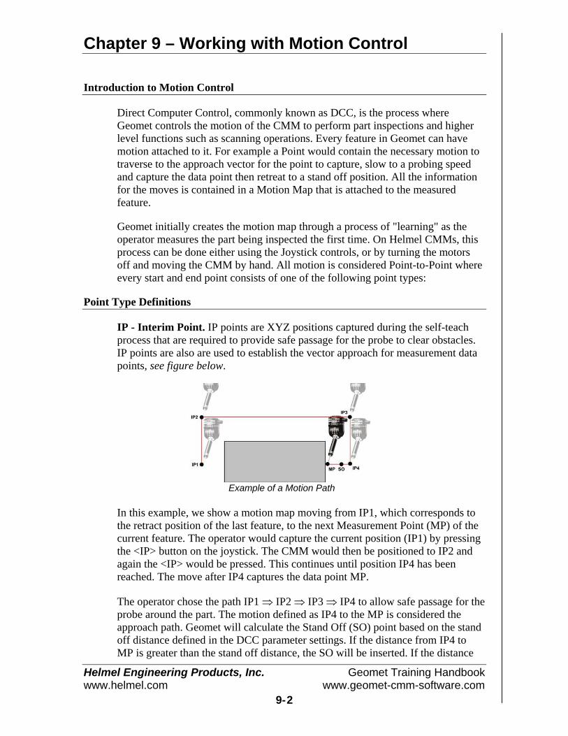
Chapter 9 – Working with Motion Control
Helmel Engineering Products, Inc. Geomet Training Handbookwww.helmel.com www.geomet-cmm-software.com
9-2
Introduction to Motion Control
Direct Computer Control, commonly known as DCC, is the process whereGeomet controls the motion of the CMM to perform part inspections and higherlevel functions such as scanning operations. Every feature in Geomet can havemotion attached to it. For example a Point would contain the necessary motion totraverse to the approach vector for the point to capture, slow to a probing speedand capture the data point then retreat to a stand off position. All the informationfor the moves is contained in a Motion Map that is attached to the measuredfeature.
Geomet initially creates the motion map through a process of "learning" as theoperator measures the part being inspected the first time. On Helmel CMMs, thisprocess can be done either using the Joystick controls, or by turning the motorsoff and moving the CMM by hand. All motion is considered Point-to-Point whereevery start and end point consists of one of the following point types:
Point Type Definitions
IP - Interim Point. IP points are XYZ positions captured during the self-teachprocess that are required to provide safe passage for the probe to clear obstacles.IP points are also are used to establish the vector approach for measurement datapoints, see figure below.
Example of a Motion Path
In this example, we show a motion map moving from IP1, which corresponds tothe retract position of the last feature, to the next Measurement Point (MP) of thecurrent feature. The operator would capture the current position (IP1) by pressingthe <IP> button on the joystick. The CMM would then be positioned to IP2 andagain the <IP> would be pressed. This continues until position IP4 has beenreached. The move after IP4 captures the data point MP.
The operator chose the path IP1 ⇒ IP2 ⇒ IP3 ⇒ IP4 to allow safe passage for theprobe around the part. The motion defined as IP4 to the MP is considered theapproach path. Geomet will calculate the Stand Off (SO) point based on the standoff distance defined in the DCC parameter settings. If the distance from IP4 toMP is greater than the stand off distance, the SO will be inserted. If the distance

Chapter 9 – Working with Motion Control
Helmel Engineering Products, Inc. Geomet Training Handbookwww.helmel.com www.geomet-cmm-software.com
9-3
from IP4 to MP is less than the distance define as the stand off distance, then IP 4becomes the SO.
There are two Stand Off points created, one before the MP and one after. Both ofthese SO points share the same XYZ location. The first SO is where Geomet willswitch from Traverse Speed to Probing Speed. The second SO which follows theMP is the retract position and the completion of a normal feature motion map.
SO - Stand Off Point. This point brackets the Measurement Point. Theproceeding SO will act as the location the motion of the CMM will slow to theProbe Speed. The SO that follows the Measurement Point is the location the probewill retract towards after the MP point has been captured.
MP - Measurement Point. The MP point is the point of contact where the probecontacts the part.
Auto-IP, Automatic IP. As the name suggests, the Auto-IP is calculated at themoment it is used during motion. This point is used when Geomet has a ClearanceCoordinate System established. The Auto-IP is defined not by an XYZ location,but by an axis of movement. If the Auto-IP is defined as using the Z-axis, then themotion will calculate a direct path from the current location into the XY plane ofthe current Clearance Coordinate System. The actual motion will be parallel to theZ-axis of the Clearance CS.
Special Considerations when Teaching Motion
The teaching of the motion path can be accomplished when motors are on and theoperator uses the joysticks, or when the motors are switched off and the operatormoves the CMM by hand. Manual operation is often the preferred method ofteaching due to the speed and ease of movement when the operator moves theCMM by hand. However manual or joystick motion can lead to erroneous IPswhen moving the CMM at a high speed.
For example, the CMM interface is responsible to control all communicationsbetween Geomet and the PMAC motion controller. The Geomet interface pollsthe PMAC motion controller at a variable rate such as 5 times per second andtransfers position and status data between Geomet and the PMAC motioncontroller with each cycle. The buttons on the joystick are interpreted by CMMinterface and transferred to the motion controller at the interface-polling rate.Therefore, when the IP button is pressed while moving 10 inches per second, theactual capturing of data can happen at worse case, 0.2 seconds later, or 2 inchesafter you pressed the IP button! The procedure of capturing an IP starts with theIP button press, then the CMM interface acknowledges the button press and sets aflag to inform the motion controller to capture an IP and return the XYZ position.This requires one cycle. Therefore when teaching a motion path that requirespositional accuracy, slow down or stop at the IP positions.

Chapter 9 – Working with Motion Control
Helmel Engineering Products, Inc. Geomet Training Handbookwww.helmel.com www.geomet-cmm-software.com
9-4
The PMAC motion controller maintains the current position of the CMM at rateshigher than 8MHz per second. When a probe trigger occurs, PMAC latches thatposition in memory and waits for the CMM interface to cycle around beforetransmitting the positional data to Geomet.
Motion Adjustment Tools
Motion paths often require adjustments due to changes in the part or the need toadjust motion to eliminate accidental collisions due to a missing IP or otherconditions. These adjustment tools are:
Motion Edit Tool Allows full adjustment of the motion map by allowing access to adjust allor a single motion point. Appending, Inserting and Moving of motionpoints can be done.
One-Step Edit This tool will provide access to adjust motion attributes (speeds anddistance) or move the entire motion map a desired relative distance.
Clearance CoordinateSystem
Clearance Coordinate Systems (CS) are defined as an offset to anexisting PCS and is used to provide safe transition planes for CMMmovement.
Offline IP The Offline IP generator allows the creation of Interim Points at thebeginning of a motion map. These points can be created as an XYZdefined point or as an Auto-IP which utilizes a Clearance CS for safetransition.
Feature Generators
Feature Generators are offline tools that can create features complete with motionand tolerance data, and when connected to a CMM, will measure the featurewithout operator involvement.
Point Generator Creates 1D, 2D and 3D Point Features in offline and interactive modes.Line Generator Creates a 2D Line Feature in offline and interactive modes.
Circle Generator Creates a 2D Circle Feature in offline and interactive modes.Cylinder Generator Creates a Cylinder Feature in offline and interactive modes.
Plane Generator Creates a Plane Feature in offline and interactive modes.Bolt Hole Pattern Creates two or more 2D Circle Features surrounding a common center
point in offline and interactive modes.
Chapter 10 details all Feature Generator tools.
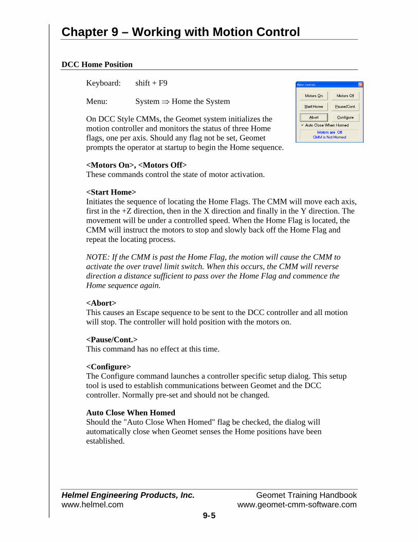
Chapter 9 – Working with Motion Control
Helmel Engineering Products, Inc. Geomet Training Handbookwww.helmel.com www.geomet-cmm-software.com
9-5
DCC Home Position
Keyboard: shift + F9
Menu: System ⇒ Home the System
On DCC Style CMMs, the Geomet system initializes themotion controller and monitors the status of three Homeflags, one per axis. Should any flag not be set, Geometprompts the operator at startup to begin the Home sequence.
<Motors On>, <Motors Off>These commands control the state of motor activation.
<Start Home>Initiates the sequence of locating the Home Flags. The CMM will move each axis,first in the +Z direction, then in the X direction and finally in the Y direction. Themovement will be under a controlled speed. When the Home Flag is located, theCMM will instruct the motors to stop and slowly back off the Home Flag andrepeat the locating process.
NOTE: If the CMM is past the Home Flag, the motion will cause the CMM toactivate the over travel limit switch. When this occurs, the CMM will reversedirection a distance sufficient to pass over the Home Flag and commence theHome sequence again.
<Abort>This causes an Escape sequence to be sent to the DCC controller and all motionwill stop. The controller will hold position with the motors on.
<Pause/Cont.>This command has no effect at this time.
<Configure>The Configure command launches a controller specific setup dialog. This setuptool is used to establish communications between Geomet and the DCCcontroller. Normally pre-set and should not be changed.
Auto Close When HomedShould the "Auto Close When Homed" flag be checked, the dialog willautomatically close when Geomet senses the Home positions have beenestablished.
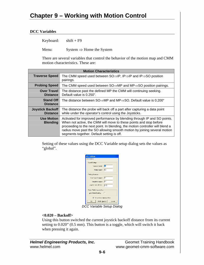
Chapter 9 – Working with Motion Control
Helmel Engineering Products, Inc. Geomet Training Handbookwww.helmel.com www.geomet-cmm-software.com
9-6
DCC Variables
Keyboard: shift + F9
Menu: System ⇒ Home the System
There are several variables that control the behavior of the motion map and CMMmotion characteristics. These are:
Motion CharacteristicsTraverse Speed The CMM speed used between SO⇒IP, IP⇒IP and IP⇒SO position
pairings.Probing Speed The CMM speed used between SO⇒MP and MP⇒SO position pairings.
Over TravelDistance
The distance past the defined MP the CMM will continuing seeking.Default value is 0.250”.
Stand OffDistance
The distance between SO⇒MP and MP⇒SO. Default value is 0.200”
Joystick BackoffDistance
The distance the probe will back off a part after capturing a data pointwhile under the operator’s control using the Joysticks.
Use MotionBlending
Activated for improved performance by blending through IP and SO points.When not active, the CMM will move to these points and stop beforeproceeding to the next point. In blending, the motion controller will blend aradius move past the SO allowing smooth motion by joining several motionsegments together. Default setting is off.
Setting of these values using the DCC Variable setup dialog sets the values as“global”.
DCC Variable Setup Dialog
<0.020 – Backoff>Using this button switched the current joystick backoff distance from its currentsetting to 0.020” (0.5 mm). This button is a toggle, which will switch it backwhen pressing it again.

Chapter 9 – Working with Motion Control
Helmel Engineering Products, Inc. Geomet Training Handbookwww.helmel.com www.geomet-cmm-software.com
9-7
Motion Control Ribbon
Motion Control Ribbon
The motion control ribbon provides a quick visual indication of the status of yourDCC style CMM as well as access to the most common controls.
Motion Ribbon Control DefinitionsToggles the Motor On and Motor Off state.The button face is Red when off, Green when on,This indicator provides a visual state between the 3 possible modes: [Man]:for motors off, [Joystick] when motors are on and Joysticks are active and[DCC] when system is under CNC control.Single Step Mode – processes one leg of motion, then pauses.
CMM Homing function. When the CMM requires the homing proceedure, thisbutton will appear on the ribbon. When the CMM is homed, this button willdisappear.Provides access to the DCC Variables Setup Tool.
This button toggles between three system level speeds defined as Normal,Slow and Extra-Slow.This drop-down tool controls the backoff distance of the joystick control. Thisis the distance the CMM will retract after capturing a data point while underthe control of the manual joysticks.This button inserts one Interim Point into the motion map for the currentposition of the active stylus.
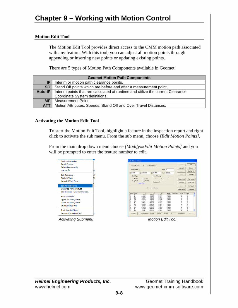
Chapter 9 – Working with Motion Control
Helmel Engineering Products, Inc. Geomet Training Handbookwww.helmel.com www.geomet-cmm-software.com
9-8
Motion Edit Tool
The Motion Edit Tool provides direct access to the CMM motion path associatedwith any feature. With this tool, you can adjust all motion points throughappending or inserting new points or updating existing points.
There are 5 types of Motion Path Components available in Geomet:
Geomet Motion Path ComponentsIP Interim or motion path clearance points.
SO Stand Off points which are before and after a measurement point.Auto-IP Interim points that are calculated at runtime and utilize the current Clearance
Coordinate System definitions.MP Measurement Point.
ATT Motion Attributes; Speeds, Stand Off and Over Travel Distances.
Activating the Motion Edit Tool
To start the Motion Edit Tool, highlight a feature in the inspection report and rightclick to activate the sub menu. From the sub menu, choose [Edit Motion Points].
From the main drop down menu choose [Modify⇒Edit Motion Points] and youwill be prompted to enter the feature number to edit.
Activating Submenu Motion Edit Tool
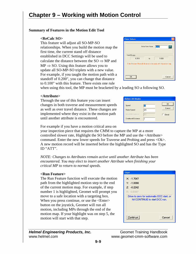
Chapter 9 – Working with Motion Control
Helmel Engineering Products, Inc. Geomet Training Handbookwww.helmel.com www.geomet-cmm-software.com
9-9
Summary of Features in the Motion Edit Tool
<ReCalc SO>This feature will adjust all SO-MP-SOrelationships. When you build the motion map thefirst time, the current stand off distanceestablished in DCC Settings will be used tocalculate the distance between the SO ⇒ MP andMP ⇒ SO. Using this feature allows you toupdate all SO-MP-SO triplets with a new value.For example, if you taught the motion path with astandoff of 0.200", you can change that distanceto 0.100" with this feature. There exists one rulewhen using this tool, the MP must be bracketed by a leading SO a following SO.
<Attribute>Through the use of this feature you can insertchanges in both traverse and measurement speedsas well as over travel distance. These changes areimplemented where they exist in the motion pathuntil another attribute is encountered.
For example if you have a motion critical area onyour inspection piece that requires the CMM to capture the MP at a morecontrolled slower rate, Highlight the SO before the MP and use the <Attribute>command. Enter the new lower speeds for Traverse and Probing and press <Ok>.A new motion record will be inserted before the highlighted SO and has the TypeID “ATT”.
NOTE: Changes to Attributes remain active until another Attribute has beenencountered. You may elect to insert another Attribute when finishing yourcritical MP to return to normal speeds.
<Run Feature>The Run Feature function will execute the motionpath from the highlighted motion step to the endof the current motion map. For example, if stepnumber 1 is highlighted, Geomet will prompt youmove to a safe location with a targeting box.When you press continue, or use the <Enter>button on the joystick, Geomet will run allmotion, including MPs through the end of themotion map. If your highlight was on step 5, themotion will start with that step.

Chapter 9 – Working with Motion Control
Helmel Engineering Products, Inc. Geomet Training Handbookwww.helmel.com www.geomet-cmm-software.com
9-10
<Single Step>The Single Step function will execute motion for just that one highlighted step.The motion will occur for all IP, SO and Auto-IP records and will not executeMPs. If the motion record has an XYZ location beyond the in-position limit, thenthe Target DRO (see Run Feature) will appear and the operator then has thechoice to manually move the CMM or use DCC to the target position. This addedstep is used to prevent potential CMM crashes if the requested location is at adistance from the current probe location.
When you highlight the leading SO, motion will take place to the XYZ location ofthe SO. Pressing single step again will skip through the MP and move to thetrailing SO for that MP. The single step feature is the tool used most to correctany motion path concerns.
<Re-Teach>In the Re-Teach function, you can highlight a location in the motion map, press<Re-Teach> and from that point down teach a new motion path creating new IPs,and SO/MPs. This function is most useful when your part program has changedand you require major changes to the motion path for the selected feature.
Start position of a ReTeach End position for the ReTeach
When starting the re-teach process, Geomet will display the targeting dialog thatshows the last location in the motion map. This becomes your start position inyour re-teach process. Manually move to this location and press <Continue>.From this point, you would create your new motion. A new target dialog willreplace the start target dialog and this new target is the next known location inyour motion map. This target will assist you in developing the new motion map.As you re-teach your finish should be near this end location for smooth transitionbetween motion maps.
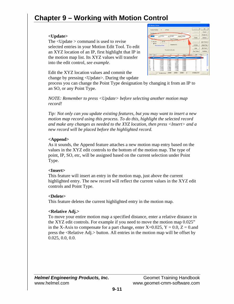
Chapter 9 – Working with Motion Control
Helmel Engineering Products, Inc. Geomet Training Handbookwww.helmel.com www.geomet-cmm-software.com
9-11
<Update>The <Update > command is used to reviseselected entries in your Motion Edit Tool. To editan XYZ location of an IP, first highlight that IP inthe motion map list. Its XYZ values will transferinto the edit control, see example.
Edit the XYZ location values and commit thechange by pressing <Update>. During the updateprocess you can change the Point Type designation by changing it from an IP toan SO, or any Point Type.
NOTE: Remember to press <Update> before selecting another motion maprecord!
Tip: Not only can you update existing features, but you may want to insert a newmotion map record using this process. To do this, highlight the selected recordand make any changes as needed to the XYZ location, then press <Insert> and anew record will be placed before the highlighted record.
<Append>As it sounds, the Append feature attaches a new motion map entry based on thevalues in the XYZ edit controls to the bottom of the motion map. The type ofpoint, IP, SO, etc, will be assigned based on the current selection under PointType.
<Insert>This feature will insert an entry in the motion map, just above the currenthighlighted entry. The new record will reflect the current values in the XYZ editcontrols and Point Type.
<Delete>This feature deletes the current highlighted entry in the motion map.
<Relative Adj.>To move your entire motion map a specified distance, enter a relative distance inthe XYZ edit controls. For example if you need to move the motion map 0.025”in the X-Axis to compensate for a part change, enter X=0.025, Y = 0.0, Z = 0.andpress the <Relative Adj.> button. All entries in the motion map will be offset by0.025, 0.0, 0.0.
Chapter 9 – Working with Motion Control
Helmel Engineering Products, Inc. Geomet Training Handbookwww.helmel.com www.geomet-cmm-software.com
9-12
NOTE: In some cases the leading IPs should not be adjusted. The motion paththat leads from the previous feature, to the start of the current feature should bereviewed carefully to ensure a relative adjustment does not cause unexpectedmotion.
Geomet offers a single tool, One-Step Motion Edit Tool, that allows a relativemotion adjustment to the entire motion map while protecting the leading IPs.
<UnSelect>This feature will drop the highlight in the motion map and clear all values in theXYZ edit controls.
<Copy>This feature takes the current highlighted motion map record and places a copy ofthat record in a buffer. Once the record is in the buffer you can Append, Insert orUpdate based on the following table:
Copy FunctionsAppend Pressing the <Append> button will attach a new motion record at the end of
the current motion map based on the copied record.Insert Highlight a location in your motion map and select <Insert>. A new record is
created and inserted before the highlighted record.Update Highlight a record in your motion map and press <Update>. The copied
record will replace the highlighted record.
<Clear>This will clear out all values in the X, Y, Z and Angle edit controls. If a motionrecord was highlighted, it remains highlighted.
Disable MotionWhen you place a check next to Disable Motion, Geomet will drop into manualmode during the part inspection when it gets to this feature. This allows theoperator to capture data points for the selected feature under Joystick or manualoperations.
When the feature is completed, Geomet looks at the next feature and if it returnsto DCC control, a targeting window is displayed to let the operator know wherethe next DCC point will start.
For a more detailed explanation, see Disable Motion and the Feature SelectionTool.
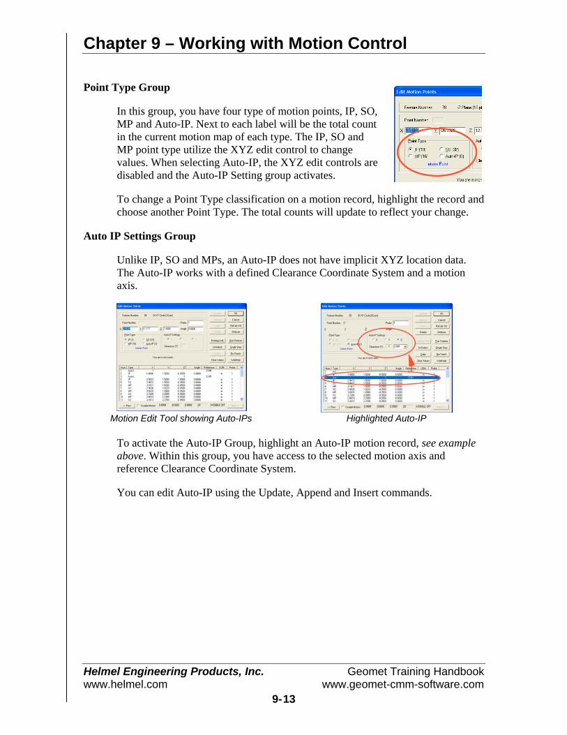
Chapter 9 – Working with Motion Control
Helmel Engineering Products, Inc. Geomet Training Handbookwww.helmel.com www.geomet-cmm-software.com
9-13
Point Type Group
In this group, you have four type of motion points, IP, SO,MP and Auto-IP. Next to each label will be the total countin the current motion map of each type. The IP, SO andMP point type utilize the XYZ edit control to changevalues. When selecting Auto-IP, the XYZ edit controls aredisabled and the Auto-IP Setting group activates.
To change a Point Type classification on a motion record, highlight the record andchoose another Point Type. The total counts will update to reflect your change.
Auto IP Settings Group
Unlike IP, SO and MPs, an Auto-IP does not have implicit XYZ location data.The Auto-IP works with a defined Clearance Coordinate System and a motionaxis.
Motion Edit Tool showing Auto-IPs Highlighted Auto-IP
To activate the Auto-IP Group, highlight an Auto-IP motion record, see exampleabove. Within this group, you have access to the selected motion axis andreference Clearance Coordinate System.
You can edit Auto-IP using the Update, Append and Insert commands.

Chapter 9 – Working with Motion Control
Helmel Engineering Products, Inc. Geomet Training Handbookwww.helmel.com www.geomet-cmm-software.com
9-14
Updating XYZ Data Directly from the CMM
The XYZ values shown in the edit controls, see figure below, will show thecurrent values of the highlighted motion point record in the list. Editing thesevalues can be accomplished either by entering new values directly by typing themin, or by pressing the <IP> button on the joystick. By moving the CMM to a newlocation and pressing the <IP> button you can quickly edit motion map data tocorrect for any problems during motion.
XYZ Position Edit Controls
An example of using the XYZ edit control would be to add an exiting IP at theend of the motion map assigned to an ID XY circle feature. The probe will stop atthe last SO of the feature which will be below the surface. To append a new IPthat will withdraw the probe to a safe location above the surface, follow thesesteps:
1) Highlight the last SO in the motion map (normally the last record). In ourexample the Z value is -0.25".
2) In the Z edit control, change the value to 0.50".3) Press the <Append> button, which will add a new record to the motion map.
NOTE: The new record added will carry forward the same Point Type as theoriginal selected SO record.
4) Highlight the new record and select the IP bullet which will change the PointType from SO to IP.
Another example can be used to create an exit IP using the same ID Circle listedabove.
1) Move the CMM into a safe location above the circle. This position should have adirect line from the last SO.
2) Press the <IP> button on the joystick. This will populate the XYZ edit controlswith the CMMs current position, see figure above.
3) Press the <Append> button in the Motion Edit tool and a new IP record will beadded at the bottom of the motion map.
In these two examples, you can start to see how easy it is to make changes to themotion map of a feature.
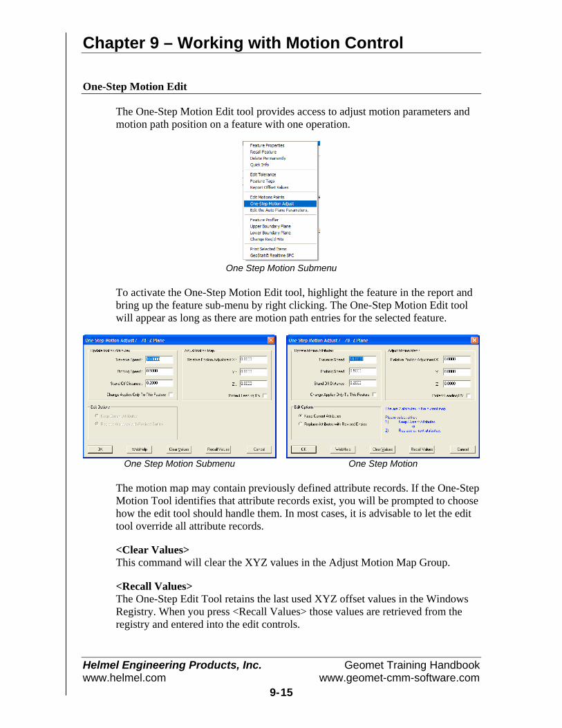
Chapter 9 – Working with Motion Control
Helmel Engineering Products, Inc. Geomet Training Handbookwww.helmel.com www.geomet-cmm-software.com
9-15
One-Step Motion Edit
The One-Step Motion Edit tool provides access to adjust motion parameters andmotion path position on a feature with one operation.
One Step Motion Submenu
To activate the One-Step Motion Edit tool, highlight the feature in the report andbring up the feature sub-menu by right clicking. The One-Step Motion Edit toolwill appear as long as there are motion path entries for the selected feature.
One Step Motion Submenu One Step Motion
The motion map may contain previously defined attribute records. If the One-StepMotion Tool identifies that attribute records exist, you will be prompted to choosehow the edit tool should handle them. In most cases, it is advisable to let the edittool override all attribute records.
<Clear Values>This command will clear the XYZ values in the Adjust Motion Map Group.
<Recall Values>The One-Step Edit Tool retains the last used XYZ offset values in the WindowsRegistry. When you press <Recall Values> those values are retrieved from theregistry and entered into the edit controls.
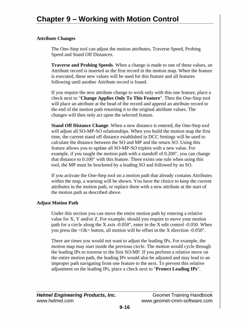
Chapter 9 – Working with Motion Control
Helmel Engineering Products, Inc. Geomet Training Handbookwww.helmel.com www.geomet-cmm-software.com
9-16
Attribute Changes
The One-Step tool can adjust the motion attributes, Traverse Speed, ProbingSpeed and Stand Off Distances.
Traverse and Probing Speeds. When a change is made to one of these values, anAttribute record is inserted as the first record in the motion map. When the featureis executed, these new values will be used for this feature and all featuresfollowing until another Attribute record is found.
If you require the new attribute change to work only with this one feature, place acheck next to "Change Applies Only To This Feature". Then the One-Step toolwill place an attribute at the head of the record and append an attribute record tothe end of the motion path returning it to the original attribute values. Thechanges will then only act upon the selected feature.
Stand Off Distance Change. When a new distance is entered, the One-Step toolwill adjust all SO-MP-SO relationships. When you build the motion map the firsttime, the current stand off distance established in DCC Settings will be used tocalculate the distance between the SO and MP and the return SO. Using thisfeature allows you to update all SO-MP-SO triplets with a new value. Forexample, if you taught the motion path with a standoff of 0.200", you can changethat distance to 0.100" with this feature. There exists one rule when using thistool, the MP must be bracketed by a leading SO and followed by an SO.
If you activate the One-Step tool on a motion path that already contains Attributeswithin the map, a warning will be shown. You have the choice to keep the currentattributes in the motion path, or replace them with a new attribute at the start ofthe motion path as described above.
Adjust Motion Path
Under this section you can move the entire motion path by entering a relativevalue for X, Y and/or Z. For example; should you require to move your motionpath for a circle along the X axis -0.050", enter in the X edit control -0.050. Whenyou press the <Ok> button, all motion will be offset in the X direction -0.050".
There are times you would not want to adjust the leading IPs. For example, themotion map may start inside the previous circle. The motion would cycle throughthe leading IPs to traverse to the first SO-MP. If you perform a relative move onthe entire motion path, the leading IPs would also be adjusted and may lead to animproper path navigating from one feature to the next. To prevent this relativeadjustment on the leading IPs, place a check next to "Protect Leading IPs".

Chapter 9 – Working with Motion Control
Helmel Engineering Products, Inc. Geomet Training Handbookwww.helmel.com www.geomet-cmm-software.com
9-17
Disable Motion on Features
From time to time during the inspection process it is helpful to drop into manualmode to capture data points on a designated feature. An example might be adiameter of a bushing that is inserted into a forging and whose position has a largevariance.
In this condition it is helpful for a DCC CMM that is running a part inspection todrop into manual mode to allow the operator to control the capturing of datapoints. Then upon completion of the feature, return to DCC control and resumethe inspection.
Applying the Disable Motion Flag
Applying the Motion Disable flag can be done through two different methods.The first of these methods involves the Motion Edit dialog previously discussed inthis chapter.
MotionEdit Tool Festure Selection Tool
In the lower left corner of the Motion Edit Dialog, you will find a check boxlabeled "Disable Motion". Place a check here to force this feature into manualmode during the inspection process. All current motion assigned to this featurewill remain visible in the Motion Edit control and during program execution willnot be acted upon. This allows switching the Disabled Motion on and offdepending on conditions.
You can use the Feature Selection Tool, discussed in chapter 7, which will allowyou to attach many Disable Motion Flags in one operation.
When using the Feature Selection Tool, highlight in the displayed list the featuresthat will get a Disable Motion Flag. Once the highlighting is completed, open thedrop down menu and choose [DCC Option⇒Disable Motion]. It is important toremember when selecting this command that it is a toggle, which sets or removesthe disabled flag.
Should you select the command [DCC Options⇒Clear all Disabled Motion], allDisable Motion flags will be cleared from the entire part inspection regardless if itwas highlighted in the list or not.
Chapter 9 – Working with Motion Control
Helmel Engineering Products, Inc. Geomet Training Handbookwww.helmel.com www.geomet-cmm-software.com
9-18
How Disabled Motion Behaves at Inspection Time
When Geomet is executing a part inspection program, it is constantly looking forthe Disable Motion flag. Should a feature with the flag be found, Geomet willdrop into manual mode to allow the operator to control the capturing of therequired data points for the feature.
When the required number of motion disabled features have been completed,Geomet will display a targeting tool that shows the location of the first motionpoint of the next feature. The targeting tool shows the XYZ relative position tothat point and the operator should joystick or manually drive the CMM to wherethe targeting box shows all zeros, or near zero. At that time, press the <Continue>button on the target tool and Geomet will return to DCC and resume partinspection.
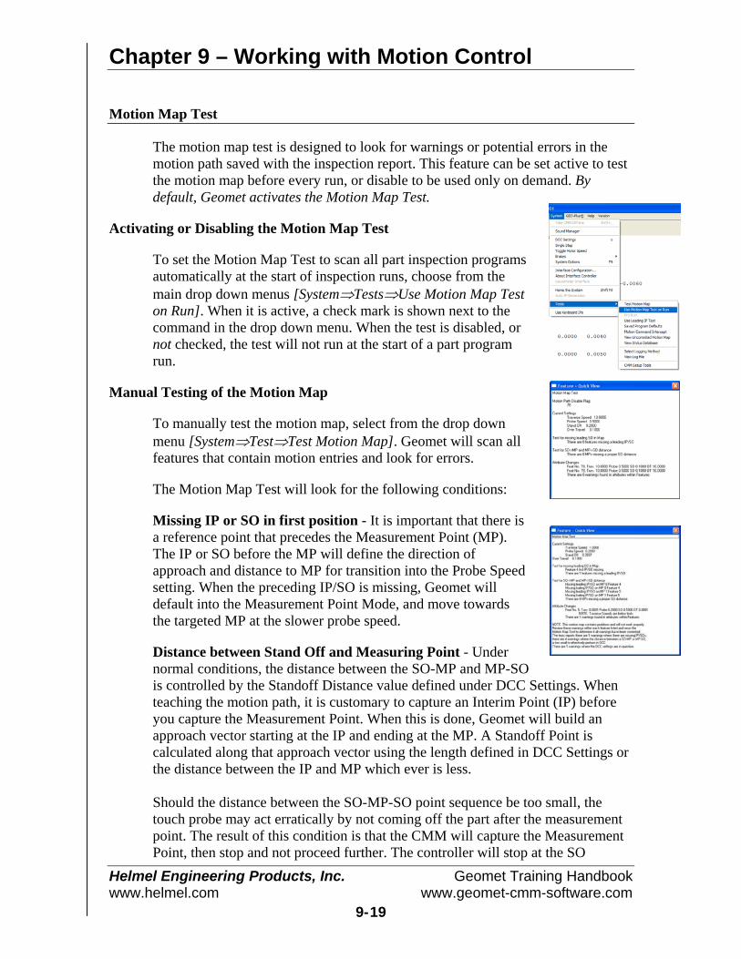
Chapter 9 – Working with Motion Control
Helmel Engineering Products, Inc. Geomet Training Handbookwww.helmel.com www.geomet-cmm-software.com
9-19
Motion Map Test
The motion map test is designed to look for warnings or potential errors in themotion path saved with the inspection report. This feature can be set active to testthe motion map before every run, or disable to be used only on demand. Bydefault, Geomet activates the Motion Map Test.
Activating or Disabling the Motion Map Test
To set the Motion Map Test to scan all part inspection programsautomatically at the start of inspection runs, choose from themain drop down menus [System⇒Tests⇒Use Motion Map Teston Run]. When it is active, a check mark is shown next to thecommand in the drop down menu. When the test is disabled, ornot checked, the test will not run at the start of a part programrun.
Manual Testing of the Motion Map
To manually test the motion map, select from the drop downmenu [System⇒Test⇒Test Motion Map]. Geomet will scan allfeatures that contain motion entries and look for errors.
The Motion Map Test will look for the following conditions:
Missing IP or SO in first position - It is important that there isa reference point that precedes the Measurement Point (MP).The IP or SO before the MP will define the direction ofapproach and distance to MP for transition into the Probe Speedsetting. When the preceding IP/SO is missing, Geomet willdefault into the Measurement Point Mode, and move towardsthe targeted MP at the slower probe speed.
Distance between Stand Off and Measuring Point - Undernormal conditions, the distance between the SO-MP and MP-SOis controlled by the Standoff Distance value defined under DCC Settings. Whenteaching the motion path, it is customary to capture an Interim Point (IP) beforeyou capture the Measurement Point. When this is done, Geomet will build anapproach vector starting at the IP and ending at the MP. A Standoff Point iscalculated along that approach vector using the length defined in DCC Settings orthe distance between the IP and MP which ever is less.
Should the distance between the SO-MP-SO point sequence be too small, thetouch probe may act erratically by not coming off the part after the measurementpoint. The result of this condition is that the CMM will capture the MeasurementPoint, then stop and not proceed further. The controller will stop at the SO
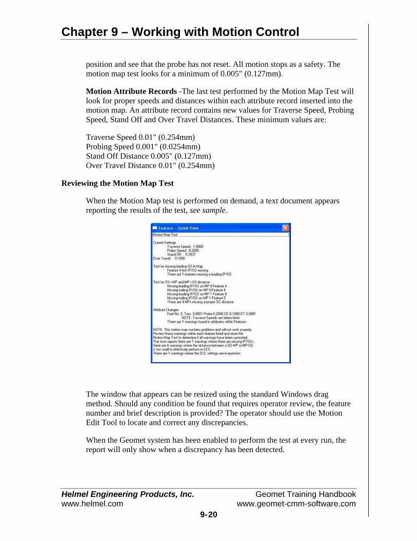
Chapter 9 – Working with Motion Control
Helmel Engineering Products, Inc. Geomet Training Handbookwww.helmel.com www.geomet-cmm-software.com
9-20
position and see that the probe has not reset. All motion stops as a safety. Themotion map test looks for a minimum of 0.005" (0.127mm).
Motion Attribute Records -The last test performed by the Motion Map Test willlook for proper speeds and distances within each attribute record inserted into themotion map. An attribute record contains new values for Traverse Speed, ProbingSpeed, Stand Off and Over Travel Distances. These minimum values are:
Traverse Speed 0.01" (0.254mm)Probing Speed 0.001" (0.0254mm)Stand Off Distance 0.005" (0.127mm)Over Travel Distance 0.01" (0.254mm)
Reviewing the Motion Map Test
When the Motion Map test is performed on demand, a text document appearsreporting the results of the test, see sample.
The window that appears can be resized using the standard Windows dragmethod. Should any condition be found that requires operator review, the featurenumber and brief description is provided? The operator should use the MotionEdit Tool to locate and correct any discrepancies.
When the Geomet system has been enabled to perform the test at every run, thereport will only show when a discrepancy has been detected.
Chapter 10 – Feature Generators
Helmel Engineering Products, Inc. Geomet Training Handbookwww.helmel.com www.geomet-cmm-software.com
10-1
Chapter 10 – Offline Tools
Introduction...................................................................................... 10-2
Feature Generators – Common Tools and Controls ........................ 10-3
Offline IP Generator ........................................................................ 10-6
Circle Generator............................................................................. 10-11
Cylinder Generator......................................................................... 10-15
Line Generator ............................................................................... 10-20
Plane Generator.............................................................................. 10-22
Point Generator .............................................................................. 10-31
Bolt Hole Generator....................................................................... 10-35

Chapter 10 – Feature Generators
Helmel Engineering Products, Inc. Geomet Training Handbookwww.helmel.com www.geomet-cmm-software.com
10-2
Introduction to Offline Auto Features
Motion Path
Offline features are used to build motion path using Clearance CoordinateSystems, Offline IP Generators and the feature nominal data. For example, youmay know the location and the corresponding Part Coordinate System for a bore.Using the Circle Generator, you can build the entire motion path and execute thecircle without involving any manual teaching.
Care should always be taken to ensure that motion commands given toautomatically traverse to the feature and then measure that feature remain clear ofall obstacles in its path.
Before you start using the feature generators, please review Clearance CoordinateSystems detailed in chapter 5.
Stylus Handling
The offline tools take into account the current active stylus configuration tocalculate the motion path. To set or change the active stylus, always use the StylusManager, refer to Chapter 3. The offline generators do not provide access tocontrolling the active stylus. With this generation of offline tools, each feature isbuilt with a single stylus tip. To utilize more than one stylus within a singlefeature, construction tools are provided.

Chapter 10 – Feature Generators
Helmel Engineering Products, Inc. Geomet Training Handbookwww.helmel.com www.geomet-cmm-software.com
10-3
Feature Generators – Common Tools and Controls
All Feature Generators in Geomet are designed with the same tools and controls.These include:
• Clearance Coordinate System• Offline IP Generation• <Update>• <Create Path>• <Execute>• <Ok>• Apply Tolerance• Auto Recalc• Draw Stylus Ball• Editing Existing Features
Clearance Coordinate Systems
One or more define coordinate systems you build surrounding your inspectionpiece. The base planes of these coordinate systems are positioned to allowunrestricted and safe motion where the CMM will traverse between features. Fora detailed explanation on setting up and using Clearance Coordinate System,please refer to Chapter 5.
Offline IP Generator
The Offline IP Generator builds the motion required to start each feature. Acomplete description of this tool follows this section.
<Update>
The Update function tests the current entered nominal data and redraws thecurrent Generator graphics. Should any nominal data be in error, the data will behighlighted in red for correction.
<Create Path>
The Create Path function calculates the full motion path based on the currententered nominal data and redraws the current Generator graphics. The Create Pathfunction will process the Update function if it was not previously completed.
Apply Tolerance
Checking this option causes the new feature to be fully toleranced based on thebilateral tolerance format.
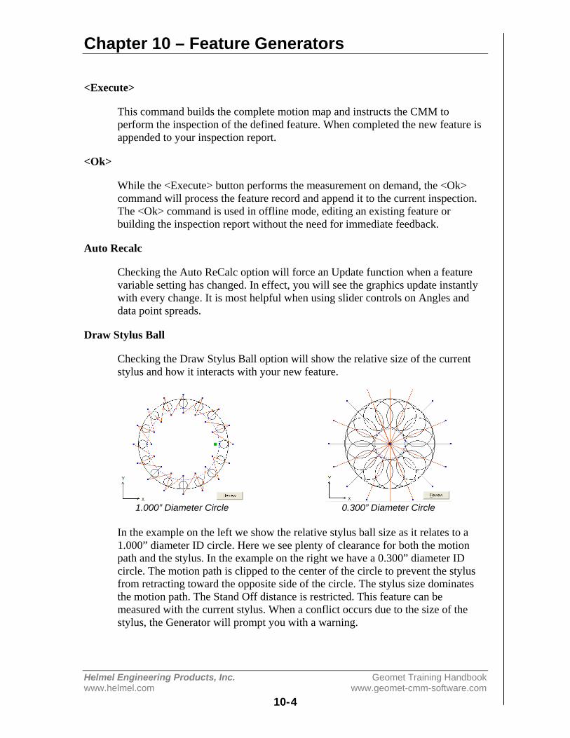
Chapter 10 – Feature Generators
Helmel Engineering Products, Inc. Geomet Training Handbookwww.helmel.com www.geomet-cmm-software.com
10-4
<Execute>
This command builds the complete motion map and instructs the CMM toperform the inspection of the defined feature. When completed the new feature isappended to your inspection report.
<Ok>
While the <Execute> button performs the measurement on demand, the <Ok>command will process the feature record and append it to the current inspection.The <Ok> command is used in offline mode, editing an existing feature orbuilding the inspection report without the need for immediate feedback.
Auto Recalc
Checking the Auto ReCalc option will force an Update function when a featurevariable setting has changed. In effect, you will see the graphics update instantlywith every change. It is most helpful when using slider controls on Angles anddata point spreads.
Draw Stylus Ball
Checking the Draw Stylus Ball option will show the relative size of the currentstylus and how it interacts with your new feature.
1.000” Diameter Circle 0.300” Diameter Circle
In the example on the left we show the relative stylus ball size as it relates to a1.000” diameter ID circle. Here we see plenty of clearance for both the motionpath and the stylus. In the example on the right we have a 0.300” diameter IDcircle. The motion path is clipped to the center of the circle to prevent the stylusfrom retracting toward the opposite side of the circle. The stylus size dominatesthe motion path. The Stand Off distance is restricted. This feature can bemeasured with the current stylus. When a conflict occurs due to the size of thestylus, the Generator will prompt you with a warning.

Chapter 10 – Feature Generators
Helmel Engineering Products, Inc. Geomet Training Handbookwww.helmel.com www.geomet-cmm-software.com
10-5
Editing Existing Features
All Feature Generators can edit existing features whether they were create with aGenerator or manually taught.
To edit an existing feature, highlight that feature in the inspection report and rightclick to activate the sub menu. Choose [Edit feature Measurement Points] (wherefeature is the name of the feature type).
Use caution when applying the generator to manually taught features. The initialMP layout will seldom conform to the ordered layout that the generator createsand any IPs inserted between the first and last MP will be discarded.
With some practice, you will learn that feature Generators can effectively be usedto edit existing features and create a more efficient motion path.
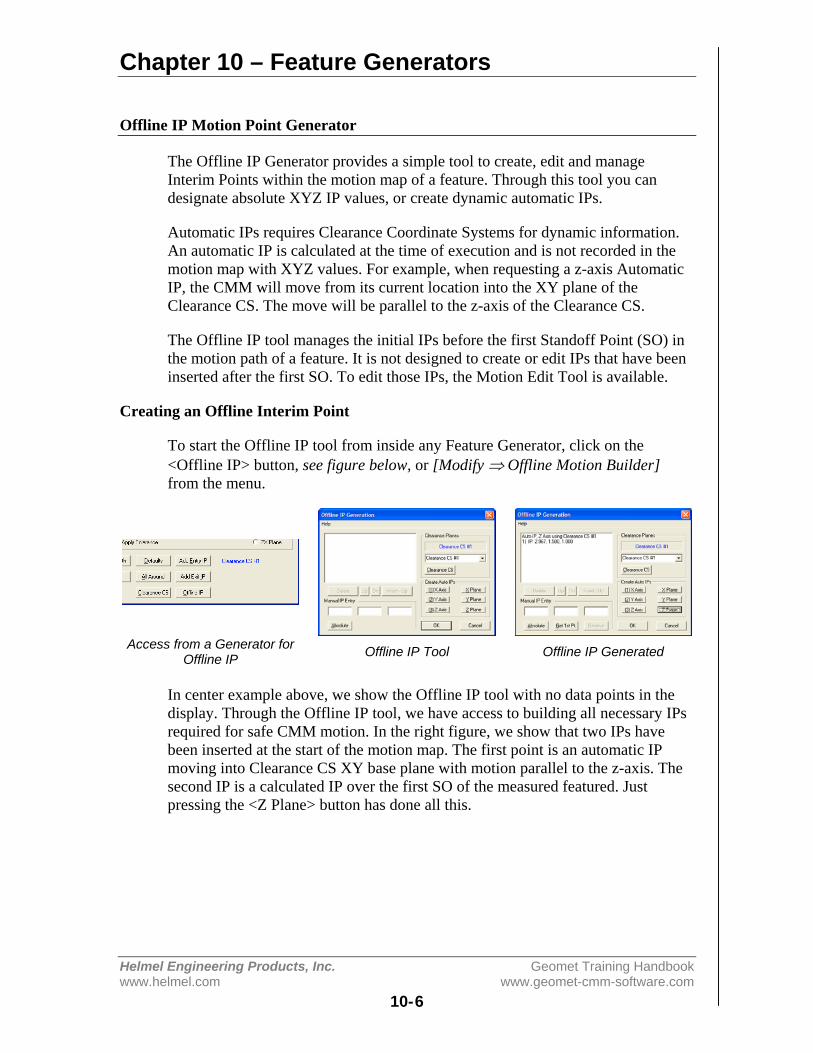
Chapter 10 – Feature Generators
Helmel Engineering Products, Inc. Geomet Training Handbookwww.helmel.com www.geomet-cmm-software.com
10-6
Offline IP Motion Point Generator
The Offline IP Generator provides a simple tool to create, edit and manageInterim Points within the motion map of a feature. Through this tool you candesignate absolute XYZ IP values, or create dynamic automatic IPs.
Automatic IPs requires Clearance Coordinate Systems for dynamic information.An automatic IP is calculated at the time of execution and is not recorded in themotion map with XYZ values. For example, when requesting a z-axis AutomaticIP, the CMM will move from its current location into the XY plane of theClearance CS. The move will be parallel to the z-axis of the Clearance CS.
The Offline IP tool manages the initial IPs before the first Standoff Point (SO) inthe motion path of a feature. It is not designed to create or edit IPs that have beeninserted after the first SO. To edit those IPs, the Motion Edit Tool is available.
Creating an Offline Interim Point
To start the Offline IP tool from inside any Feature Generator, click on the<Offline IP> button, see figure below, or [Modify ⇒ Offline Motion Builder]from the menu.
Access from a Generator forOffline IP Offline IP Tool Offline IP Generated
In center example above, we show the Offline IP tool with no data points in thedisplay. Through the Offline IP tool, we have access to building all necessary IPsrequired for safe CMM motion. In the right figure, we show that two IPs havebeen inserted at the start of the motion map. The first point is an automatic IPmoving into Clearance CS XY base plane with motion parallel to the z-axis. Thesecond IP is a calculated IP over the first SO of the measured featured. Justpressing the <Z Plane> button has done all this.

Chapter 10 – Feature Generators
Helmel Engineering Products, Inc. Geomet Training Handbookwww.helmel.com www.geomet-cmm-software.com
10-7
Offline IP Tool Layout
The Offline IP Tool contains three groupsof controls, plus a list of IPs that areassigned. The first group belongs toManual IP Entry. From this control, youcan create absolute positioned XYZ IPs,relative positioned IPs and obtain the XYZlocation of the first SO in the feature.
The next group accesses the Clearance Planes. All automatic IPs require that aClearance CS is defined and set active. The <Clearance CS> button activates theClearance CS tool to create, edit and activate a Clearance CS, see ClearanceCoordinate Systems in Chapter 5 for more detail.
The final group is called Create Auto IPs. There are six buttons that createautomatic IPs. The buttons labeled X, Y and Z-axis, which will create anautomatic IP that moves parallel to the selected Clearance CS axis into theselected base plane. The buttons labeled X, Y and Z Plane creates two IPs. Thefirst is an Automatic IP and the second is a calculated IP over the measuredfeature.
Manual IP Entry Group
Within the Manual IP Entry Group there are three edit controls for XYZ values.These work with Absolute IPs, Relative IPs and Get 1st Point functions.
Absolute IPs
To create an IP with absolute coordinates enter theXYZ PCS values in the edit control.
In this example, we entered:
X = 2.9672Y = 1.500Z = -0.05
To confirm and create the IP, Press the <Absolute> button. An entry of the newlycreated IP will be shown in the display area.

Chapter 10 – Feature Generators
Helmel Engineering Products, Inc. Geomet Training Handbookwww.helmel.com www.geomet-cmm-software.com
10-8
Relative IPs
The Relative IP function creates a new IP at an offset distance from thehighlighted IP in the list. Start by selecting an IP in the display.
Entering a Relative IP Position New Relative IP Position added
As shown in the left figure, we have selected the first IP. When the IP has beenselected, the <Relative> button becomes active. Enter the XYZ offset distance inthe edit controls. We show the example of entering:
X = 1Y = 1Z = 0
Complete the process by pressing the <Relative> button. A new IP is created thathas an offset value of X=1.0, Y=1.0, Z=0.0 from the selected IP, see the rightfigure.
Get 1st Point
This command retrieves the first Standoff position in the current motion path. Asshown in the illustration, the first Standoff Point is:
X = 2.9672Y = 1.5000Z = -0.0500
The XYZ location of the first Standoff Point is helpful when you are creating anew IP. For example, if we are creating an XY Circle, with a probing depth that isidentified by the Z value (-0.0500). We would want an IP over the SO Point thatwill allow for safe motion of the probe. We can change the Z value of the firstpoint to 0.5" and press the <Absolute> button. Now we have an IP directly overthe first SO Point. The probe will move to that point, then plunge into the hole tocommence measurement.
Chapter 10 – Feature Generators
Helmel Engineering Products, Inc. Geomet Training Handbookwww.helmel.com www.geomet-cmm-software.com
10-9
NOTE: The Get 1st Point command works with the motion path alreadydetermined in the Feature Generator tool. In this example we are using a 2D XYCircle. If you change the sweep start value, then the first SO will change. Whenyou change any path-generating variable, you should return to the Offline IP toolto confirm the IP originally created is also updated.
Clearance Planes
This group provides a simple drop down control which lists all the currentClearance CS systems in your inspection. Choose the Clearance CS you wantactive before you start assigning Automatic IPs.
<Clearance CS>
The Clearance CS button provides access to the Clearance Coordinate SystemSetup Tool. This tool allows you to update and create Clearance CS. For detailedinformation on Clearance CS, see chapter 5.
Create Auto IPs
To create Auto IPs, you must first have a Clearance CS active. If the six Auto IPgeneration buttons are disabled, there is no Clearance CS active.
<X Axis>, <Y Axis>, <Z Axis>
These commands will create an Automatic IP based on the axis selected. Forexample, the X-axis command will create an IP that moves from the currentCMM location into the Clearance CS YZ Base plane by moving parallel to the x-axis.
<X Plane>, <Y Plane>, <Z Plane>
These commands create two-IPs in your motion path. If you press <Z Plane>, thefirst IP created is an Automatic IP that moves from the current point parallel tothe z-axis of the Clearance CS into the XY Base plane. Similar to pressing the <ZAxis> button.
The second IP created is the entry IP for your current feature. It is calculated bytaking the first SO in the motion path and projecting that into the Clearance CSXY Base plane. In most applications, this is all that is needed to move safely fromone location to the start of the feature.

Chapter 10 – Feature Generators
Helmel Engineering Products, Inc. Geomet Training Handbookwww.helmel.com www.geomet-cmm-software.com
10-10
For example, if measuring two XY circles, to move from circle number 1 to circlenumber 2, we would select the Z Plane command in the Offline IP tool. Uponcompletion of measuring circle number 1, the probe is at the probe depth belowthe surface of the part. The Z Plane command will first extract the probe in a pure+Z direction into the XY Base plane of the defined Clearance CS, then transitionin the same XY Base plane until it is over the first point of the second feature.From this point, the probe can now plunge into the second circle to commencemeasuring.
Display List Controls
The display list showing the offline IPs has controls identified as <Delete>,<Up>, <Dn> and <Insert - Up>. These allow you to control and position the IPsas needed.
<Delete>
Allows you to delete from the list the current selected IP.
<Up>, <Dn>
These commands reposition the selected IP either Up or Down in the list.
<Insert – Up>
This command acts similar to the creating an IP using the Absolute command.However, unlike the Absolute command which always appends a new point to thebottom of the list, the <Insert - Up> command inserts a new absolute IP in thesame location as the selected IP and moves all other IPs down.
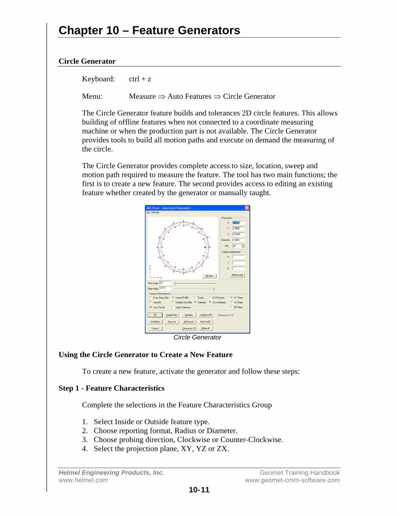
Chapter 10 – Feature Generators
Helmel Engineering Products, Inc. Geomet Training Handbookwww.helmel.com www.geomet-cmm-software.com
10-11
Circle Generator
Keyboard: ctrl + z
Menu: Measure ⇒ Auto Features ⇒ Circle Generator
The Circle Generator feature builds and tolerances 2D circle features. This allowsbuilding of offline features when not connected to a coordinate measuringmachine or when the production part is not available. The Circle Generatorprovides tools to build all motion paths and execute on demand the measuring ofthe circle.
The Circle Generator provides complete access to size, location, sweep andmotion path required to measure the feature. The tool has two main functions; thefirst is to create a new feature. The second provides access to editing an existingfeature whether created by the generator or manually taught.
Circle Generator
Using the Circle Generator to Create a New Feature
To create a new feature, activate the generator and follow these steps:
Step 1 - Feature Characteristics
Complete the selections in the Feature Characteristics Group
1. Select Inside or Outside feature type.2. Choose reporting format, Radius or Diameter.3. Choose probing direction, Clockwise or Counter-Clockwise.4. Select the projection plane, XY, YZ or ZX.
Chapter 10 – Feature Generators
Helmel Engineering Products, Inc. Geomet Training Handbookwww.helmel.com www.geomet-cmm-software.com
10-12
Step 2 - Feature Parameters
Complete the values required in the Parameters Group
1. Enter the XYZ Circle Center.2. Enter the Radius or Diameter nominal value.3. Select the number of hits required.4. Set the Start Angle and Stop Angle.
NOTE: when entering the XYZ center location it is important that you establish aprobing depth sufficient to clear chamfers and edges. For example: if a borebeing measured has nominal values of X=1.000, Y=1.000, Z=0.000. You woulddefine the circle with a Z component that would include clearance below the topsurface, such as a Z=-0.100". When the motion is executed, the data points will becaptured at a depth of -0.100" below the top surface ensuring the data pointsclear all possible edge and chamfer conditions.
Step 3 - Motion Path Adjustments
There are several tools available to build motion paths to ensure clear motionwithout collision into the inspection part, clamps and other obstacles. Theseinclude Clearance Coordinate Systems, offline IPs and Automatic IPs.
Creating Offline IPs and Automatic IPs
Once the Clearance Coordinate System has been established and set active,Offline IPs can be generated to build a motion path for safe CMM travel, seeOffline IPs in the beginning of this chapter.
Special Interim Point Commands
In most applications, the use of the command <Add Entry IP> and <Add Exit IP>will ensure safe transition for your CMM into and out of features. The use ofthese commands requires that a Clearance CS is currently set active.
The Add Entry IP command will calculate an IP directly over the feature in thenormal base plane. For example, in the XY circle example, the first Standoff Pointis extracted and projected into the XY Base plane of the active Clearance CS. Themotion will start directly over the hole and plunge to the first SO safely.
The Add Exit IP command creates a similar IP to Add Entry IP except it will usethe last SO as its reference. The combination of these two commands results inthe CMM moving directly over the first SO, perform the measurement and exitthe hole safely.

Chapter 10 – Feature Generators
Helmel Engineering Products, Inc. Geomet Training Handbookwww.helmel.com www.geomet-cmm-software.com
10-13
Miscellaneous Functions
<All Around>
This will recalculate the motion path to evenly distribute the data points aroundthe circle. When there are 4 data points, each data point will measure at:
Data Point #1 - 0°Data Point #2 - 90°Data Point #3 - 180°Data Point #4 - 270°
The motion path generator will determine the optimal motion path including theinsertion of IPs between data points to prevent collision with the part. This isespecially important when measuring outside diameters.
<Defaults>
Geomet has built in defaults for feature generators. In the circle generator, theDefault command will create a 16-point feature using the All Around motion pathgenerator.
Relative Adjustment
The Relative Adjustment command will offset the current XYZ values a specifieddistance. This is helpful when measuring similar features. An example would be aseries of five 0.375" diameter holes 1.00" apart in the X direction. Build andexecute the first hole using the Circle Generator. When the feature has beencompleted, activating the Circle Generator will display the last known values, orin this case, the parameters of hole number one. Enter 1,0,0 in the RelativeAdjustment group and press <Perform Adj>, the hole center XYZ values willupdate and if you are using Entry and Exit IPs, just press the Execute commandand the CMM will transition and measure hole number two.
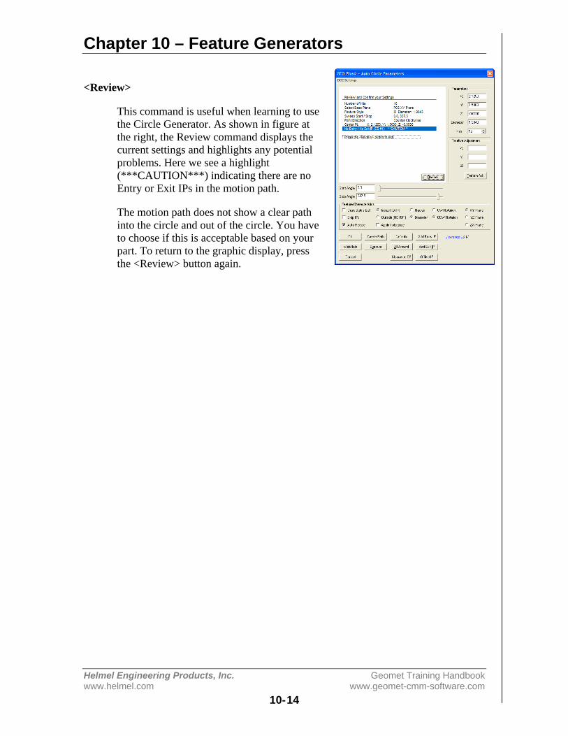
Chapter 10 – Feature Generators
Helmel Engineering Products, Inc. Geomet Training Handbookwww.helmel.com www.geomet-cmm-software.com
10-14
<Review>
This command is useful when learning to usethe Circle Generator. As shown in figure atthe right, the Review command displays thecurrent settings and highlights any potentialproblems. Here we see a highlight(***CAUTION***) indicating there are noEntry or Exit IPs in the motion path.
The motion path does not show a clear pathinto the circle and out of the circle. You haveto choose if this is acceptable based on yourpart. To return to the graphic display, pressthe <Review> button again.

Chapter 10 – Feature Generators
Helmel Engineering Products, Inc. Geomet Training Handbookwww.helmel.com www.geomet-cmm-software.com
10-15
Cylinder Generator
Keyboard: ctrl + c
Menu: Measure ⇒ Auto Features ⇒ Cylinder Generator
The Cylinder Generator will build and tolerance Cylinder features. This allowsbuilding of offline features when not connected to a coordinate measuringmachine or when the production part is not available. The Cylinder Generator alsobuilds all motion paths and can execute on demand the measuring of the newcylinder.
The Cylinder Generator provides complete access to size, location, start / stopangles and motion path generators required to measure the feature. The tool hastwo functions. The first is to create a new feature. The second provides access toediting an existing feature whether created by the generator or manually taught.
Circle Generator
Using the Cylinder Generator to Create a New Feature
To create a new feature, activate the generator and follow these steps:
Step 1 - Feature Characteristics
Complete the selections in the Feature Characteristics Group
1. Select Inside or Outside feature type.2. Choose reporting format, Radius or Diameter.3. Choose probing direction, Clockwise or Counter-Clockwise.
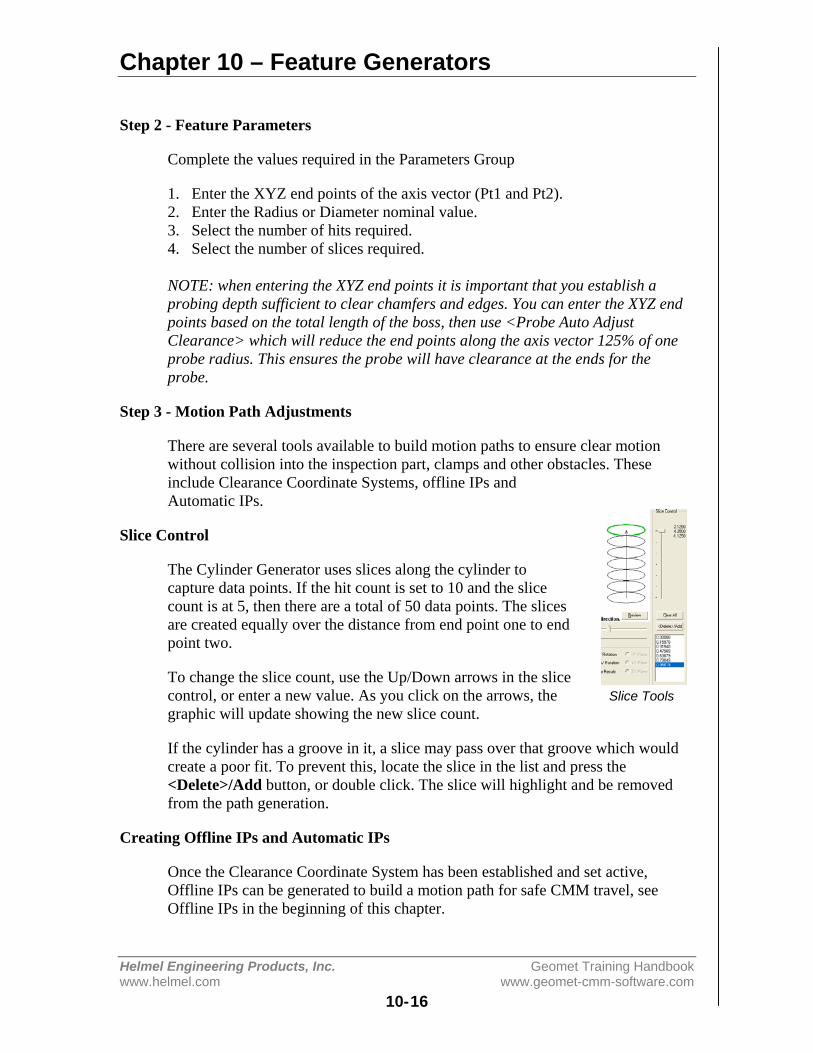
Chapter 10 – Feature Generators
Helmel Engineering Products, Inc. Geomet Training Handbookwww.helmel.com www.geomet-cmm-software.com
10-16
Step 2 - Feature Parameters
Complete the values required in the Parameters Group
1. Enter the XYZ end points of the axis vector (Pt1 and Pt2).2. Enter the Radius or Diameter nominal value.3. Select the number of hits required.4. Select the number of slices required.
NOTE: when entering the XYZ end points it is important that you establish aprobing depth sufficient to clear chamfers and edges. You can enter the XYZ endpoints based on the total length of the boss, then use <Probe Auto AdjustClearance> which will reduce the end points along the axis vector 125% of oneprobe radius. This ensures the probe will have clearance at the ends for theprobe.
Step 3 - Motion Path Adjustments
There are several tools available to build motion paths to ensure clear motionwithout collision into the inspection part, clamps and other obstacles. Theseinclude Clearance Coordinate Systems, offline IPs andAutomatic IPs.
Slice Control
The Cylinder Generator uses slices along the cylinder tocapture data points. If the hit count is set to 10 and the slicecount is at 5, then there are a total of 50 data points. The slicesare created equally over the distance from end point one to endpoint two.
To change the slice count, use the Up/Down arrows in the slicecontrol, or enter a new value. As you click on the arrows, thegraphic will update showing the new slice count.
If the cylinder has a groove in it, a slice may pass over that groove which wouldcreate a poor fit. To prevent this, locate the slice in the list and press the<Delete>/Add button, or double click. The slice will highlight and be removedfrom the path generation.
Creating Offline IPs and Automatic IPs
Once the Clearance Coordinate System has been established and set active,Offline IPs can be generated to build a motion path for safe CMM travel, seeOffline IPs in the beginning of this chapter.
Slice Tools
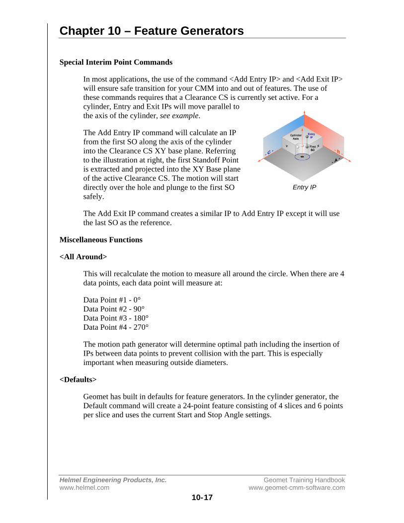
Chapter 10 – Feature Generators
Helmel Engineering Products, Inc. Geomet Training Handbookwww.helmel.com www.geomet-cmm-software.com
10-17
Special Interim Point Commands
In most applications, the use of the command <Add Entry IP> and <Add Exit IP>will ensure safe transition for your CMM into and out of features. The use ofthese commands requires that a Clearance CS is currently set active. For acylinder, Entry and Exit IPs will move parallel tothe axis of the cylinder, see example.
The Add Entry IP command will calculate an IPfrom the first SO along the axis of the cylinderinto the Clearance CS XY base plane. Referringto the illustration at right, the first Standoff Pointis extracted and projected into the XY Base planeof the active Clearance CS. The motion will startdirectly over the hole and plunge to the first SOsafely.
The Add Exit IP command creates a similar IP to Add Entry IP except it will usethe last SO as the reference.
Miscellaneous Functions
<All Around>
This will recalculate the motion to measure all around the circle. When there are 4data points, each data point will measure at:
Data Point #1 - 0°Data Point #2 - 90°Data Point #3 - 180°Data Point #4 - 270°
The motion path generator will determine optimal path including the insertion ofIPs between data points to prevent collision with the part. This is especiallyimportant when measuring outside diameters.
<Defaults>
Geomet has built in defaults for feature generators. In the cylinder generator, theDefault command will create a 24-point feature consisting of 4 slices and 6 pointsper slice and uses the current Start and Stop Angle settings.
Entry IP

Chapter 10 – Feature Generators
Helmel Engineering Products, Inc. Geomet Training Handbookwww.helmel.com www.geomet-cmm-software.com
10-18
Translate Endpoints
The Translate Endpoint command is a relative adjustmentcommand which will offset the current XYZ values of eachendpoint a specified distance. This is helpful when measuringsimilar features. An example would be a series of five 0.500"diameter holes 1.00" apart in the X direction. Build and executethe first hole using the Cylinder Generator. When the feature hasbeen completed, activate the Cylinder Generator and the lastnominal values will be displayed, or in this case, the parametersof hole number one.
From the drop down selector, choose [Translate Endpoints]. Enter 1,0,0 in theRelative Adjustment group and press <Ok>, the end points will translate by theXYZ values. Follow that by updating the Entry and Exit IPs if required. Press the<Execute> command and the CMM will engage motors and measure hole numbertwo following the motion path built by the Cylinder Generator.
Translate
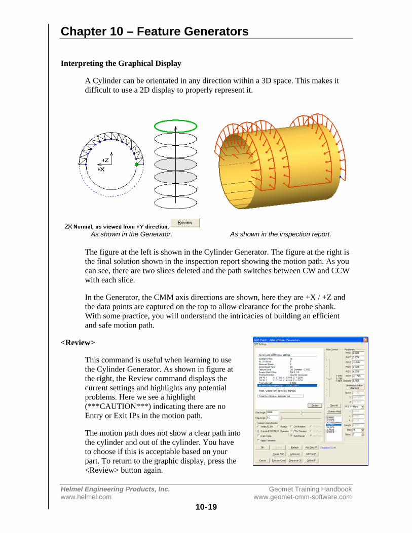
Chapter 10 – Feature Generators
Helmel Engineering Products, Inc. Geomet Training Handbookwww.helmel.com www.geomet-cmm-software.com
10-19
Interpreting the Graphical Display
A Cylinder can be orientated in any direction within a 3D space. This makes itdifficult to use a 2D display to properly represent it.
As shown in the Generator. As shown in the inspection report.
The figure at the left is shown in the Cylinder Generator. The figure at the right isthe final solution shown in the inspection report showing the motion path. As youcan see, there are two slices deleted and the path switches between CW and CCWwith each slice.
In the Generator, the CMM axis directions are shown, here they are +X / +Z andthe data points are captured on the top to allow clearance for the probe shank.With some practice, you will understand the intricacies of building an efficientand safe motion path.
<Review>
This command is useful when learning to usethe Cylinder Generator. As shown in figure atthe right, the Review command displays thecurrent settings and highlights any potentialproblems. Here we see a highlight(***CAUTION***) indicating there are noEntry or Exit IPs in the motion path.
The motion path does not show a clear path intothe cylinder and out of the cylinder. You haveto choose if this is acceptable based on yourpart. To return to the graphic display, press the<Review> button again.
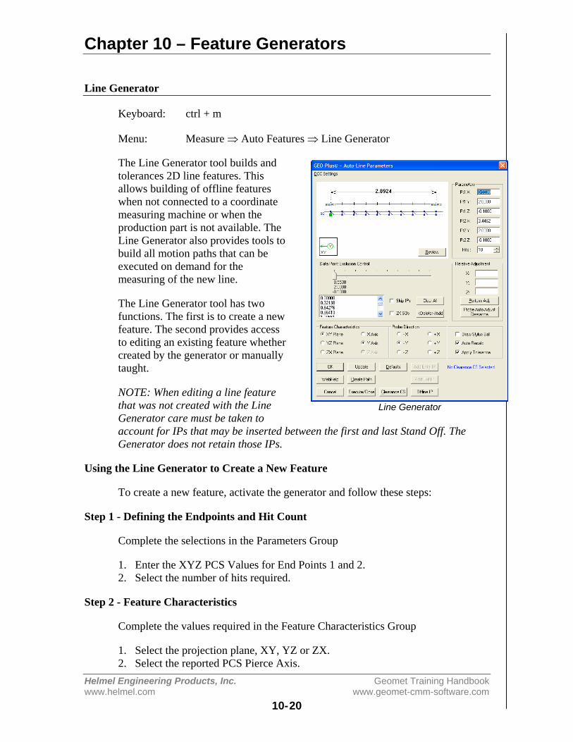
Chapter 10 – Feature Generators
Helmel Engineering Products, Inc. Geomet Training Handbookwww.helmel.com www.geomet-cmm-software.com
10-20
Line Generator
Keyboard: ctrl + m
Menu: Measure ⇒ Auto Features ⇒ Line Generator
The Line Generator tool builds andtolerances 2D line features. Thisallows building of offline featureswhen not connected to a coordinatemeasuring machine or when theproduction part is not available. TheLine Generator also provides tools tobuild all motion paths that can beexecuted on demand for themeasuring of the new line.
The Line Generator tool has twofunctions. The first is to create a newfeature. The second provides accessto editing an existing feature whethercreated by the generator or manuallytaught.
NOTE: When editing a line featurethat was not created with the LineGenerator care must be taken toaccount for IPs that may be inserted between the first and last Stand Off. TheGenerator does not retain those IPs.
Using the Line Generator to Create a New Feature
To create a new feature, activate the generator and follow these steps:
Step 1 - Defining the Endpoints and Hit Count
Complete the selections in the Parameters Group
1. Enter the XYZ PCS Values for End Points 1 and 2.2. Select the number of hits required.
Step 2 - Feature Characteristics
Complete the values required in the Feature Characteristics Group
1. Select the projection plane, XY, YZ or ZX.2. Select the reported PCS Pierce Axis.
Line Generator
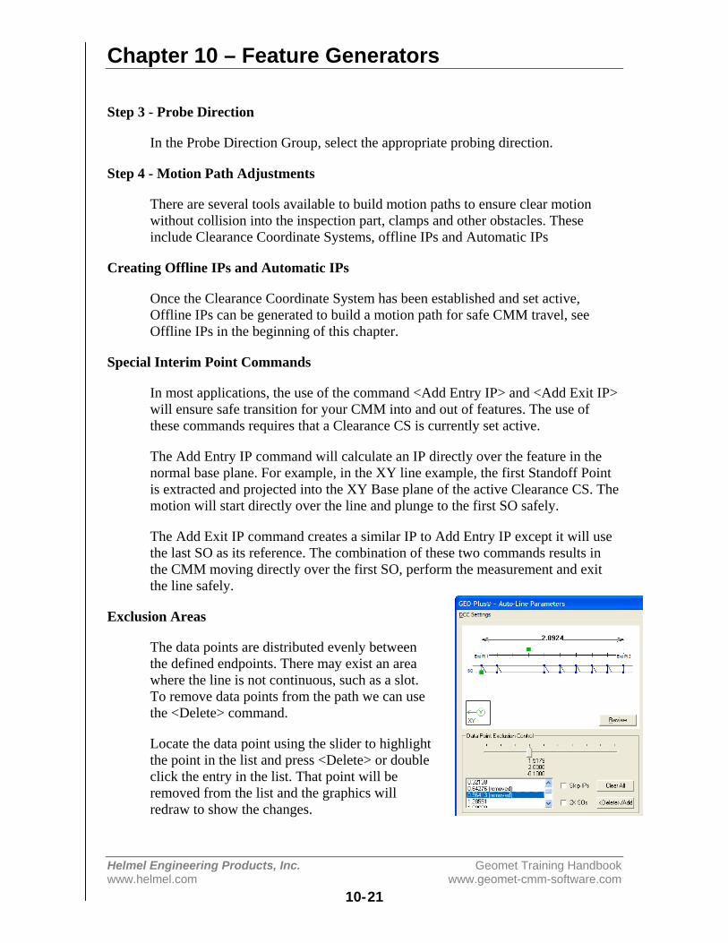
Chapter 10 – Feature Generators
Helmel Engineering Products, Inc. Geomet Training Handbookwww.helmel.com www.geomet-cmm-software.com
10-21
Step 3 - Probe Direction
In the Probe Direction Group, select the appropriate probing direction.
Step 4 - Motion Path Adjustments
There are several tools available to build motion paths to ensure clear motionwithout collision into the inspection part, clamps and other obstacles. Theseinclude Clearance Coordinate Systems, offline IPs and Automatic IPs
Creating Offline IPs and Automatic IPs
Once the Clearance Coordinate System has been established and set active,Offline IPs can be generated to build a motion path for safe CMM travel, seeOffline IPs in the beginning of this chapter.
Special Interim Point Commands
In most applications, the use of the command <Add Entry IP> and <Add Exit IP>will ensure safe transition for your CMM into and out of features. The use ofthese commands requires that a Clearance CS is currently set active.
The Add Entry IP command will calculate an IP directly over the feature in thenormal base plane. For example, in the XY line example, the first Standoff Pointis extracted and projected into the XY Base plane of the active Clearance CS. Themotion will start directly over the line and plunge to the first SO safely.
The Add Exit IP command creates a similar IP to Add Entry IP except it will usethe last SO as its reference. The combination of these two commands results inthe CMM moving directly over the first SO, perform the measurement and exitthe line safely.
Exclusion Areas
The data points are distributed evenly betweenthe defined endpoints. There may exist an areawhere the line is not continuous, such as a slot.To remove data points from the path we can usethe <Delete> command.
Locate the data point using the slider to highlightthe point in the list and press <Delete> or doubleclick the entry in the list. That point will beremoved from the list and the graphics willredraw to show the changes.
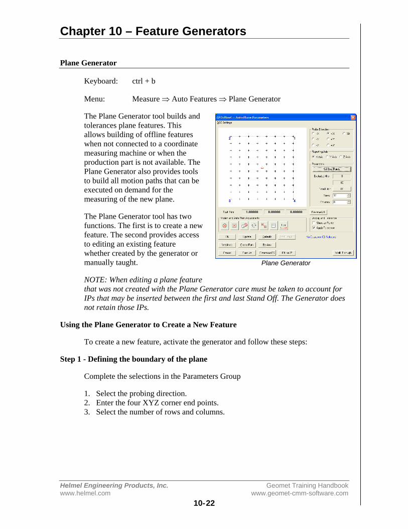
Chapter 10 – Feature Generators
Helmel Engineering Products, Inc. Geomet Training Handbookwww.helmel.com www.geomet-cmm-software.com
10-22
Plane Generator
Keyboard: ctrl + b
Menu: Measure ⇒ Auto Features ⇒ Plane Generator
The Plane Generator tool builds andtolerances plane features. Thisallows building of offline featureswhen not connected to a coordinatemeasuring machine or when theproduction part is not available. ThePlane Generator also provides toolsto build all motion paths that can beexecuted on demand for themeasuring of the new plane.
The Plane Generator tool has twofunctions. The first is to create a newfeature. The second provides accessto editing an existing featurewhether created by the generator ormanually taught.
NOTE: When editing a plane featurethat was not created with the Plane Generator care must be taken to account forIPs that may be inserted between the first and last Stand Off. The Generator doesnot retain those IPs.
Using the Plane Generator to Create a New Feature
To create a new feature, activate the generator and follow these steps:
Step 1 - Defining the boundary of the plane
Complete the selections in the Parameters Group
1. Select the probing direction.2. Enter the four XYZ corner end points.3. Select the number of rows and columns.
Plane Generator
Chapter 10 – Feature Generators
Helmel Engineering Products, Inc. Geomet Training Handbookwww.helmel.com www.geomet-cmm-software.com
10-23
Step 2 - Feature Characteristics
Complete the values required in the Feature Characteristics Group
1. Reverse IJK if required.2. Select the reported PCS Pierce Axis.
Step 3 – Exclusion Zones
Exclusion Zones are added to the plane to account for portions of the surfacewhere a hole or slot may cut through. Data points defined by the row and columnpositions may fall within these exclusion features. The Exclusion Zones removesthose data points from the final motion map.
Step 4 - Motion Path Adjustments
There are several tools available to build motion paths to ensure clear motionwithout collision into the part, clamps and other obstacles. These includeClearance Coordinate Systems, offline IPs and Automatic IPs
Creating Offline IPs and Automatic IPs
Once the Clearance Coordinate System has been established and set active,Offline IPs can be generated to build a motion path for safe CMM travel, seeOffline IPs in the beginning of this chapter.
Special Interim Point Commands
In most applications, the use of the command <Add Entry IP> and <Add Exit IP>will ensure safe transition for your CMM into and out of features. The use ofthese commands requires that a Clearance CS is currently set active.
The Add Entry IP command will calculate an IP directly over the feature in thenormal base plane. For example, in the XY line example, the first Standoff Pointis extracted and projected into the XY Base plane of the active Clearance CS. Themotion will start directly over the line and plunge to the first SO safely.
The Add Exit IP command creates a similar IP to Add Entry IP except it will usethe last SO as its reference. The combination of these two commands results inthe CMM moving directly over the first SO, perform the measurement and exitthe line safely.
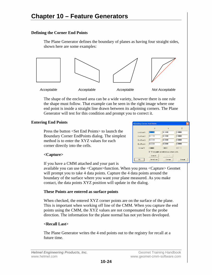
Chapter 10 – Feature Generators
Helmel Engineering Products, Inc. Geomet Training Handbookwww.helmel.com www.geomet-cmm-software.com
10-24
Defining the Corner End Points
The Plane Generator defines the boundary of planes as having four straight sides,shown here are some examples:
Acceptable Acceptable Acceptable Not Acceptable
The shape of the enclosed area can be a wide variety, however there is one rulethe shape must follow. That example can be seen in the right image where oneend point is inside a straight line drawn between its adjoining corners. The PlaneGenerator will test for this condition and prompt you to correct it.
Entering End Points
Press the button <Set End Points> to launch theBoundary Corner EndPoints dialog. The simplestmethod is to enter the XYZ values for eachcorner directly into the cells.
<Capture>
If you have a CMM attached and your part isavailable you can use the <Capture>function. When you press <Capture> Geometwill prompt you to take 4 data points. Capture the 4 data points around theboundary of the surface where you want your plane measured. As you makecontact, the data points XYZ position will update in the dialog.
These Points are entered as surface points
When checked, the entered XYZ corner points are on the surface of the plane.This is important when working off line of the CMM. When you capture the endpoints using the CMM, the XYZ values are not compensated for the probedirection. The information for the plane normal has not yet been developed.
<Recall Last>
The Plane Generator writes the 4 end points out to the registry for recall at afuture time.
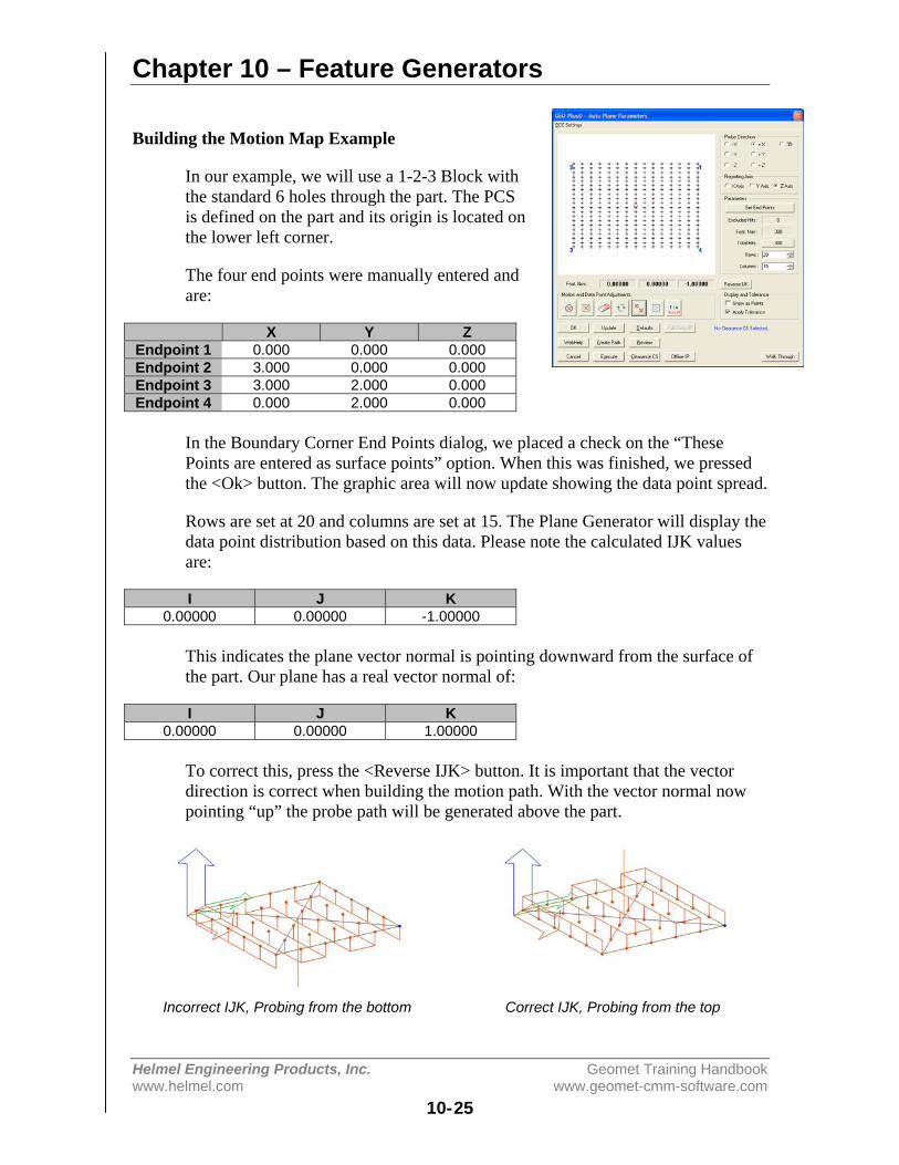
Chapter 10 – Feature Generators
Helmel Engineering Products, Inc. Geomet Training Handbookwww.helmel.com www.geomet-cmm-software.com
10-25
Building the Motion Map Example
In our example, we will use a 1-2-3 Block withthe standard 6 holes through the part. The PCSis defined on the part and its origin is located onthe lower left corner.
The four end points were manually entered andare:
X Y ZEndpoint 1 0.000 0.000 0.000Endpoint 2 3.000 0.000 0.000Endpoint 3 3.000 2.000 0.000Endpoint 4 0.000 2.000 0.000
In the Boundary Corner End Points dialog, we placed a check on the “ThesePoints are entered as surface points” option. When this was finished, we pressedthe <Ok> button. The graphic area will now update showing the data point spread.
Rows are set at 20 and columns are set at 15. The Plane Generator will display thedata point distribution based on this data. Please note the calculated IJK valuesare:
I J K0.00000 0.00000 -1.00000
This indicates the plane vector normal is pointing downward from the surface ofthe part. Our plane has a real vector normal of:
I J K0.00000 0.00000 1.00000
To correct this, press the <Reverse IJK> button. It is important that the vectordirection is correct when building the motion path. With the vector normal nowpointing “up” the probe path will be generated above the part.
Incorrect IJK, Probing from the bottom Correct IJK, Probing from the top

Chapter 10 – Feature Generators
Helmel Engineering Products, Inc. Geomet Training Handbookwww.helmel.com www.geomet-cmm-software.com
10-26
Data Point Edge Clearance
In our example we are using a 1-2-3 block and ourendpoints that define the plane boundary are the realedges of the part. This is not a good practice as ourCMM will move to the exact edge and capture datapoints. Since our stylus is a sphere, we will getquestionable data points that will give you anerroneous result.
To remedy this condition we could have enteredcorner points that are inside the physical boundaries,or we can scale our endpoints using the <Scale>tool.
The value you enter in the Scale Dialog is a percentage of the total boundary area.In this example, we entered 0.95. The scale function reduces the total area bymultiplying each axis by 0.95. The final corner points are then determined fromthe original center point effectively shrinking the area to be used in the motionpath generation.
Original Entered Values Values After ScalingX Y Z X Y Z
Endpt 1 0.0000 0.0000 0.0000 0.0750 0.0500 0.0000Endpt 2 3.0000 0.0000 0.0000 2.9250 0.0500 0.0000Endpt 3 3.0000 2.0000 0.0000 2.9250 1.9500 0.0000Endpt 4 0.0000 2.0000 0.0000 0.0750 1.9500 0.0000
With the scaling operation completed, we now have a safe distance between theedge of the physical part and where the data points are captured.
Exclusion Zones
To eliminate data points from the grid, the Plane Generator provides three tools.
Radial Exclusion Zone defined by a center point and radius. All data points thatfall within this zone will be removed from the motion map. The Radial ExclusionZone is a fixed position that does not scale.
Boundary Exclusion Zone is defined by 4 endpoints. All data points that fallwithin this zone will be removed from the motion map. The Boundary ExclusionZone is a fixed position that does not scale.
This tool creates a small 0.05” radius Target Exclusion. The center position of thezone is positioned with mouse. As you position over a existing data point, ananchor shows, left click to set the zone.
Scale Button
Enter Scale Value

Chapter 10 – Feature Generators
Helmel Engineering Products, Inc. Geomet Training Handbookwww.helmel.com www.geomet-cmm-software.com
10-27
Radial Exclusion Zone
The Radial Exclusion Zone is used to delete datapoints from the motion map where a hole mightexist on the surface that would interfere with
measuring of a plane. There are many options availablein building Radial Exclusion Zones.
Basic Radial Exclusion Zone
Using our 1-2-3 block example we have 6 holes, orareas where no data points should be taken. Enter theXYZ center for the first hole:
X Y Z0.50000 0.50000 0.00000
Now enter the radius of the hole, which is 0.250” and press <Ok>. The examplebelow shows the removal of data points for that one exclusion zone.
One Radial Exclusion Zone Enlarged Exclusion Zone
Care should be taken when entering empirical sizes for the exclusion zone.Although the radius of the hole is 0.250”, that will not take into account positionchanges or a chamfer on the edge of the hole. To account for this use the toolsavailable in the Clearance Compensation Group. We could place a check next toAdd and enter a value of 0.035 in the Additional Amount control. This will beadded to the entered radius value and enlarge the exclusion zone as shown above,right.
Should you have selected Subtract in the Clearance Compensation Group, theradius would have been reduced by that amount.
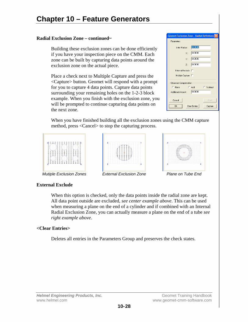
Chapter 10 – Feature Generators
Helmel Engineering Products, Inc. Geomet Training Handbookwww.helmel.com www.geomet-cmm-software.com
10-28
Radial Exclusion Zone – continued~
Building these exclusion zones can be done efficientlyif you have your inspection piece on the CMM. Eachzone can be built by capturing data points around theexclusion zone on the actual piece.
Place a check next to Multiple Capture and press the<Capture> button. Geomet will respond with a promptfor you to capture 4 data points. Capture data pointssurrounding your remaining holes on the 1-2-3 blockexample. When you finish with the exclusion zone, youwill be prompted to continue capturing data points onthe next zone.
When you have finished building all the exclusion zones using the CMM capturemethod, press <Cancel> to stop the capturing process.
Mutiple Exclusion Zones External Exclusion Zone Plane on Tube End
External Exclude
When this option is checked, only the data points inside the radial zone are kept.All data point outside are excluded, see center example above. This can be usedwhen measuring a plane on the end of a cylinder and if combined with an InternalRadial Exclusion Zone, you can actually measure a plane on the end of a tube seeright example above.
<Clear Entries>
Deletes all entries in the Parameters Group and preserves the check states.
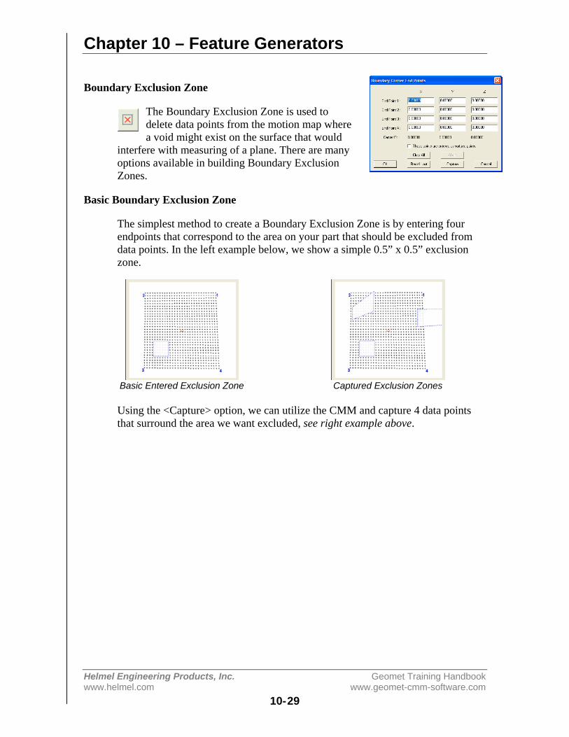
Chapter 10 – Feature Generators
Helmel Engineering Products, Inc. Geomet Training Handbookwww.helmel.com www.geomet-cmm-software.com
10-29
Boundary Exclusion Zone
The Boundary Exclusion Zone is used todelete data points from the motion map wherea void might exist on the surface that would
interfere with measuring of a plane. There are manyoptions available in building Boundary ExclusionZones.
Basic Boundary Exclusion Zone
The simplest method to create a Boundary Exclusion Zone is by entering fourendpoints that correspond to the area on your part that should be excluded fromdata points. In the left example below, we show a simple 0.5” x 0.5” exclusionzone.
Basic Entered Exclusion Zone Captured Exclusion Zones
Using the <Capture> option, we can utilize the CMM and capture 4 data pointsthat surround the area we want excluded, see right example above.
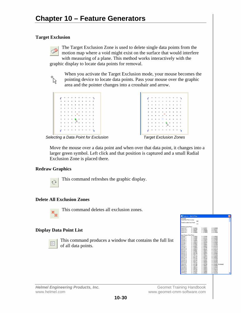
Chapter 10 – Feature Generators
Helmel Engineering Products, Inc. Geomet Training Handbookwww.helmel.com www.geomet-cmm-software.com
10-30
Target Exclusion
The Target Exclusion Zone is used to delete single data points from themotion map where a void might exist on the surface that would interferewith measuring of a plane. This method works interactively with the
graphic display to locate data points for removal.
When you activate the Target Exclusion mode, your mouse becomes thepointing device to locate data points. Pass your mouse over the graphicarea and the pointer changes into a crosshair and arrow.
Selecting a Data Point for Exclusion Target Exclusion Zones
Move the mouse over a data point and when over that data point, it changes into alarger green symbol. Left click and that position is captured and a small RadialExclusion Zone is placed there.
Redraw Graphics
This command refreshes the graphic display.
Delete All Exclusion Zones
This command deletes all exclusion zones.
Display Data Point List
This command produces a window that contains the full listof all data points.
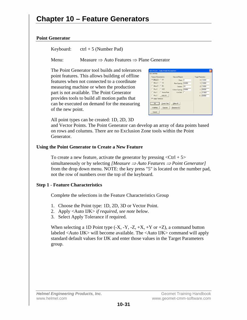
Chapter 10 – Feature Generators
Helmel Engineering Products, Inc. Geomet Training Handbookwww.helmel.com www.geomet-cmm-software.com
10-31
Point Generator
Keyboard: ctrl + 5 (Number Pad)
Menu: Measure ⇒ Auto Features ⇒ Plane Generator
The Point Generator tool builds and tolerancespoint features. This allows building of offlinefeatures when not connected to a coordinatemeasuring machine or when the productionpart is not available. The Point Generatorprovides tools to build all motion paths thatcan be executed on demand for the measuringof the new point.
All point types can be created: 1D, 2D, 3Dand Vector Points. The Point Generator can develop an array of data points basedon rows and columns. There are no Exclusion Zone tools within the PointGenerator.
Using the Point Generator to Create a New Feature
To create a new feature, activate the generator by pressing <Ctrl + 5>simultaneously or by selecting [Measure ⇒ Auto Features ⇒ Point Generator]from the drop down menu. NOTE: the key press "5" is located on the number pad,not the row of numbers over the top of the keyboard.
Step 1 - Feature Characteristics
Complete the selections in the Feature Characteristics Group
1. Choose the Point type: 1D, 2D, 3D or Vector Point.2. Apply <Auto IJK> if required, see note below.3. Select Apply Tolerance if required.
When selecting a 1D Point type (-X, -Y, -Z, +X, +Y or +Z), a command buttonlabeled <Auto IJK> will become available. The <Auto IJK> command will applystandard default values for IJK and enter those values in the Target Parametersgroup.
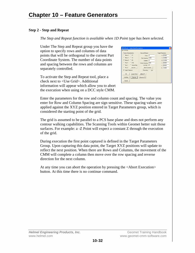
Chapter 10 – Feature Generators
Helmel Engineering Products, Inc. Geomet Training Handbookwww.helmel.com www.geomet-cmm-software.com
10-32
Step 2 - Step and Repeat
The Step and Repeat function is available when 1D Point type has been selected.
Under The Step and Repeat group you have theoption to specify rows and columns of datapoints that will be orthogonal to the current PartCoordinate System. The number of data pointsand spacing between the rows and columns areseparately controlled.
To activate the Step and Repeat tool, place acheck next to <Use Grid>. Additionalinformation will appear which allow you to abortthe execution when using on a DCC style CMM.
Enter the parameters for the row and column count and spacing. The value youenter for Row and Column Spacing are sign sensitive. These spacing values areapplied against the XYZ position entered in Target Parameters group, which isconsidered the starting point of the grid.
The grid is assumed to be parallel to a PCS base plane and does not perform anycontour walking capabilities. The Scanning Tools within Geomet better suit thosesurfaces. For example: a -Z Point will expect a constant Z through the executionof the grid.
During execution the first point captured is defined in the Target ParametersGroup. Upon capturing this data point, the Target XYZ positions will update toreflect the next position. When there are Rows and Columns, the movement of theCMM will complete a column then move over the row spacing and reversedirection for the next column.
At any time you can abort the operation by pressing the <Abort Execution>button. At this time there is no continue command.
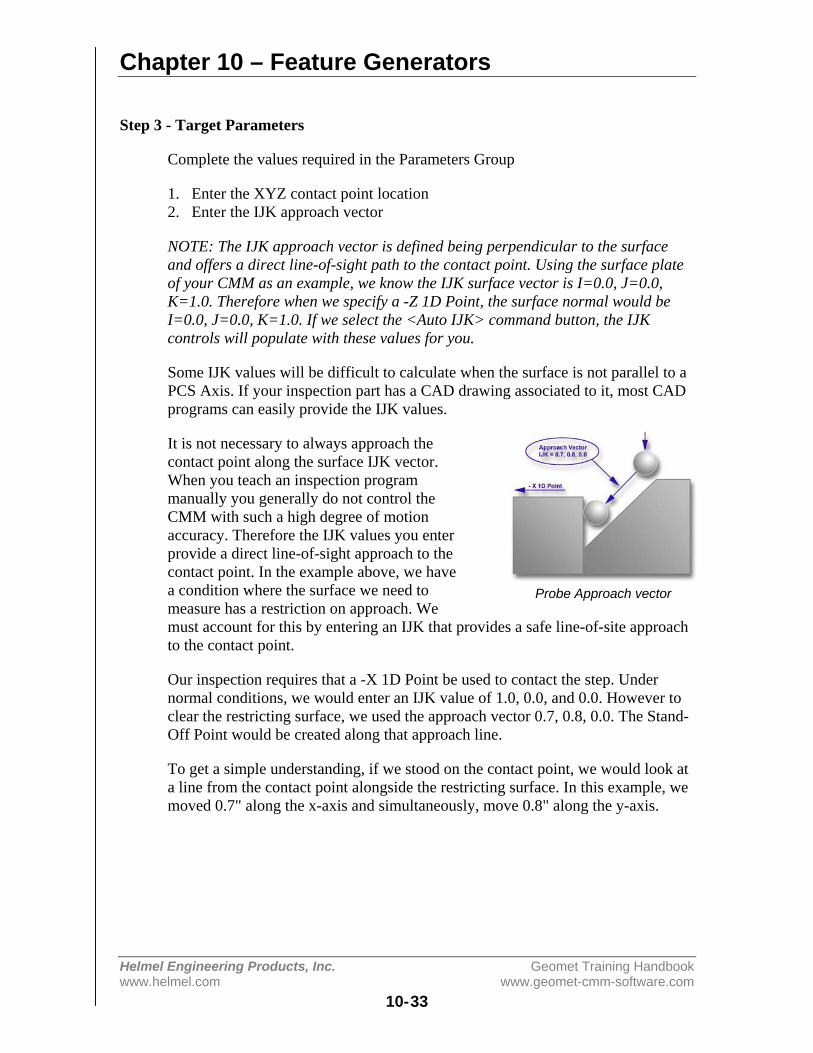
Chapter 10 – Feature Generators
Helmel Engineering Products, Inc. Geomet Training Handbookwww.helmel.com www.geomet-cmm-software.com
10-33
Step 3 - Target Parameters
Complete the values required in the Parameters Group
1. Enter the XYZ contact point location2. Enter the IJK approach vector
NOTE: The IJK approach vector is defined being perpendicular to the surfaceand offers a direct line-of-sight path to the contact point. Using the surface plateof your CMM as an example, we know the IJK surface vector is I=0.0, J=0.0,K=1.0. Therefore when we specify a -Z 1D Point, the surface normal would beI=0.0, J=0.0, K=1.0. If we select the <Auto IJK> command button, the IJKcontrols will populate with these values for you.
Some IJK values will be difficult to calculate when the surface is not parallel to aPCS Axis. If your inspection part has a CAD drawing associated to it, most CADprograms can easily provide the IJK values.
It is not necessary to always approach thecontact point along the surface IJK vector.When you teach an inspection programmanually you generally do not control theCMM with such a high degree of motionaccuracy. Therefore the IJK values you enterprovide a direct line-of-sight approach to thecontact point. In the example above, we havea condition where the surface we need tomeasure has a restriction on approach. Wemust account for this by entering an IJK that provides a safe line-of-site approachto the contact point.
Our inspection requires that a -X 1D Point be used to contact the step. Undernormal conditions, we would enter an IJK value of 1.0, 0.0, and 0.0. However toclear the restricting surface, we used the approach vector 0.7, 0.8, 0.0. The Stand-Off Point would be created along that approach line.
To get a simple understanding, if we stood on the contact point, we would look ata line from the contact point alongside the restricting surface. In this example, wemoved 0.7" along the x-axis and simultaneously, move 0.8" along the y-axis.
Probe Approach vector
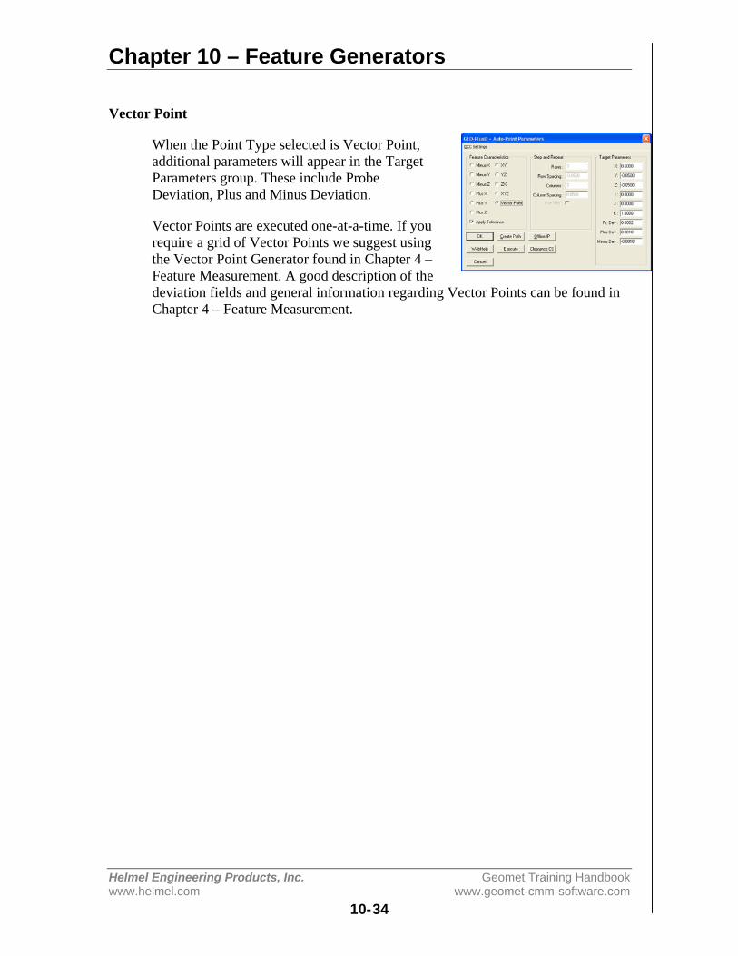
Chapter 10 – Feature Generators
Helmel Engineering Products, Inc. Geomet Training Handbookwww.helmel.com www.geomet-cmm-software.com
10-34
Vector Point
When the Point Type selected is Vector Point,additional parameters will appear in the TargetParameters group. These include ProbeDeviation, Plus and Minus Deviation.
Vector Points are executed one-at-a-time. If yourequire a grid of Vector Points we suggest usingthe Vector Point Generator found in Chapter 4 –Feature Measurement. A good description of thedeviation fields and general information regarding Vector Points can be found inChapter 4 – Feature Measurement.
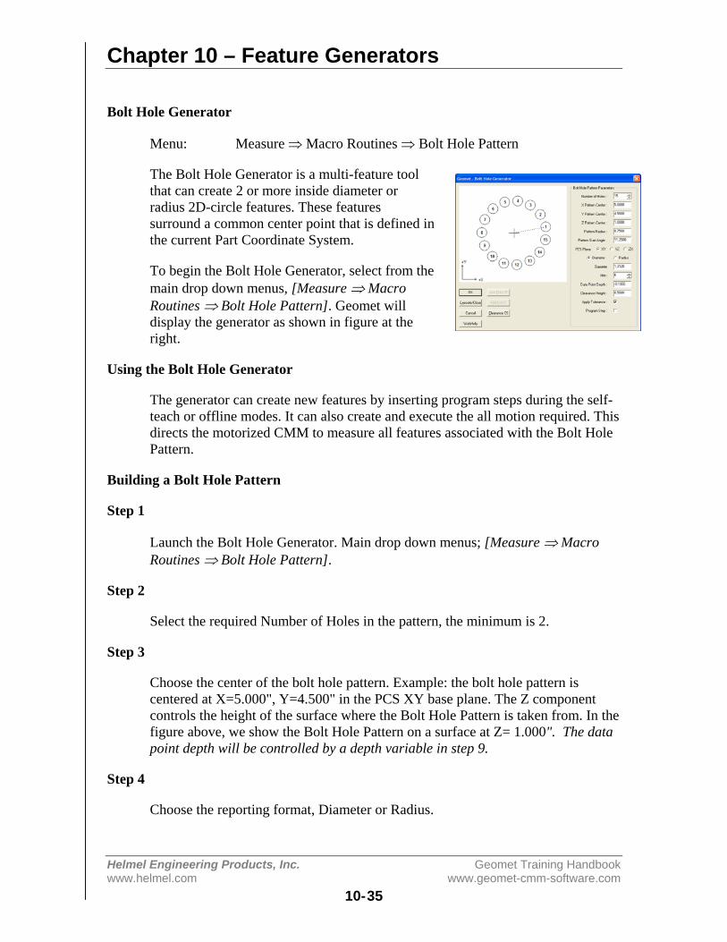
Chapter 10 – Feature Generators
Helmel Engineering Products, Inc. Geomet Training Handbookwww.helmel.com www.geomet-cmm-software.com
10-35
Bolt Hole Generator
Menu: Measure ⇒ Macro Routines ⇒ Bolt Hole Pattern
The Bolt Hole Generator is a multi-feature toolthat can create 2 or more inside diameter orradius 2D-circle features. These featuressurround a common center point that is defined inthe current Part Coordinate System.
To begin the Bolt Hole Generator, select from themain drop down menus, [Measure ⇒ MacroRoutines ⇒ Bolt Hole Pattern]. Geomet willdisplay the generator as shown in figure at theright.
Using the Bolt Hole Generator
The generator can create new features by inserting program steps during the self-teach or offline modes. It can also create and execute the all motion required. Thisdirects the motorized CMM to measure all features associated with the Bolt HolePattern.
Building a Bolt Hole Pattern
Step 1
Launch the Bolt Hole Generator. Main drop down menus; [Measure ⇒ MacroRoutines ⇒ Bolt Hole Pattern].
Step 2
Select the required Number of Holes in the pattern, the minimum is 2.
Step 3
Choose the center of the bolt hole pattern. Example: the bolt hole pattern iscentered at X=5.000", Y=4.500" in the PCS XY base plane. The Z componentcontrols the height of the surface where the Bolt Hole Pattern is taken from. In thefigure above, we show the Bolt Hole Pattern on a surface at Z= 1.000". The datapoint depth will be controlled by a depth variable in step 9.
Step 4
Choose the reporting format, Diameter or Radius.
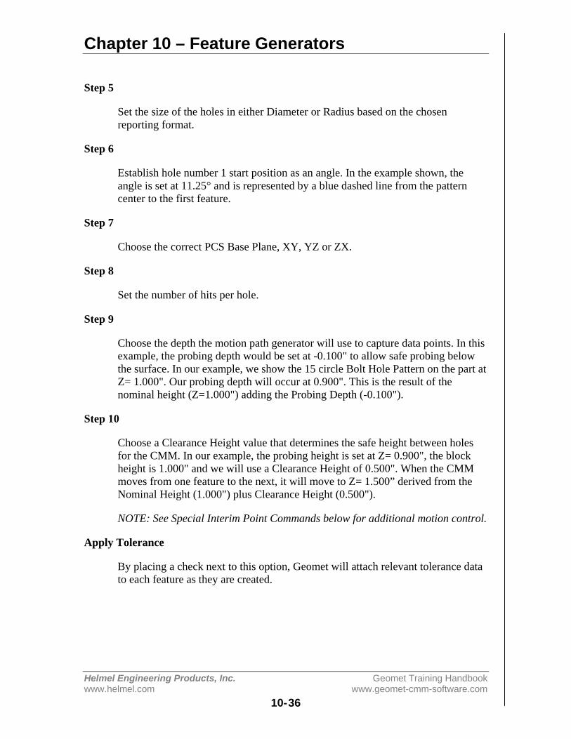
Chapter 10 – Feature Generators
Helmel Engineering Products, Inc. Geomet Training Handbookwww.helmel.com www.geomet-cmm-software.com
10-36
Step 5
Set the size of the holes in either Diameter or Radius based on the chosenreporting format.
Step 6
Establish hole number 1 start position as an angle. In the example shown, theangle is set at 11.25° and is represented by a blue dashed line from the patterncenter to the first feature.
Step 7
Choose the correct PCS Base Plane, XY, YZ or ZX.
Step 8
Set the number of hits per hole.
Step 9
Choose the depth the motion path generator will use to capture data points. In thisexample, the probing depth would be set at -0.100" to allow safe probing belowthe surface. In our example, we show the 15 circle Bolt Hole Pattern on the part atZ= 1.000". Our probing depth will occur at 0.900". This is the result of thenominal height (Z=1.000") adding the Probing Depth (-0.100").
Step 10
Choose a Clearance Height value that determines the safe height between holesfor the CMM. In our example, the probing height is set at Z= 0.900", the blockheight is 1.000" and we will use a Clearance Height of 0.500". When the CMMmoves from one feature to the next, it will move to Z= 1.500” derived from theNominal Height (1.000") plus Clearance Height (0.500").
NOTE: See Special Interim Point Commands below for additional motion control.
Apply Tolerance
By placing a check next to this option, Geomet will attach relevant tolerance datato each feature as they are created.
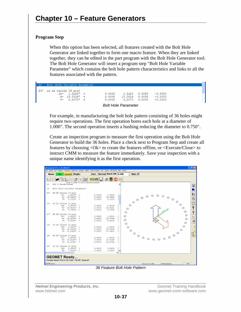
Chapter 10 – Feature Generators
Helmel Engineering Products, Inc. Geomet Training Handbookwww.helmel.com www.geomet-cmm-software.com
10-37
Program Step
When this option has been selected, all features created with the Bolt HoleGenerator are linked together to form one macro feature. When they are linkedtogether, they can be edited in the part program with the Bolt Hole Generator tool.The Bolt Hole Generator will insert a program step "Bolt Hole VariableParameter" which contains the bolt hole pattern characteristics and links to all thefeatures associated with the pattern.
Bolt Hole Parameter
For example, in manufacturing the bolt hole pattern consisting of 36 holes mightrequire two operations. The first operation bores each hole at a diameter of1.000". The second operation inserts a bushing reducing the diameter to 0.750".
Create an inspection program to measure the first operation using the Bolt HoleGenerator to build the 36 holes. Place a check next to Program Step and create allfeatures by choosing <Ok> to create the features offline, or <Execute/Close> toinstruct CMM to measure the feature immediately. Save your inspection with aunique name identifying it as the first operation.
36 Feature Bolt Hole Pattern
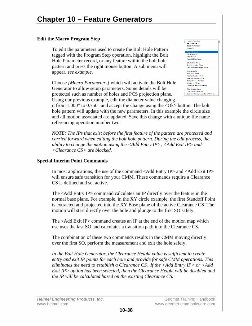
Chapter 10 – Feature Generators
Helmel Engineering Products, Inc. Geomet Training Handbookwww.helmel.com www.geomet-cmm-software.com
10-38
Edit the Macro Program Step
To edit the parameters used to create the Bolt Hole Patterntagged with the Program Step operation, highlight the BoltHole Parameter record, or any feature within the bolt holepattern and press the right mouse button. A sub menu willappear, see example.
Choose [Macro Parameters] which will activate the Bolt HoleGenerator to allow setup parameters. Some details will beprotected such as number of holes and PCS projection plane.Using our previous example, edit the diameter value changingit from 1.000” to 0.750" and accept the change using the <Ok> button. The bolthole pattern will update with the new parameters. In this example the circle sizeand all motion associated are updated. Save this change with a unique file namereferencing operation number two.
NOTE: The IPs that exist before the first feature of the pattern are protected andcarried forward when editing the bolt hole pattern. During the edit process, theability to change the motion using the <Add Entry IP>, <Add Exit IP> and<Clearance CS> are blocked.
Special Interim Point Commands
In most applications, the use of the command <Add Entry IP> and <Add Exit IP>will ensure safe transition for your CMM. These commands require a ClearanceCS is defined and set active.
The <Add Entry IP> command calculates an IP directly over the feature in thenormal base plane. For example, in the XY circle example, the first Standoff Pointis extracted and projected into the XY Base plane of the active Clearance CS. Themotion will start directly over the hole and plunge to the first SO safely.
The <Add Exit IP> command creates an IP at the end of the motion map whichuse uses the last SO and calculates a transition path into the Clearance CS.
The combination of these two commands results in the CMM moving directlyover the first SO, perform the measurement and exit the hole safely.
In the Bolt Hole Generator, the Clearance Height value is sufficient to createentry and exit IP points for each hole and provide for safe CMM operations. Thiseliminates the need to establish a Clearance CS. If the <Add Entry IP> or <AddExit IP> option has been selected, then the Clearance Height will be disabled andthe IP will be calculated based on the existing Clearance CS.
Chapter 11 – Reverse Engineering
Helmel Engineering Products, Inc. Geomet Training Handbookwww.helmel.com www.geomet-cmm-software.com
11-1
Chapter 11 – Reverse Engineering
Introduction...................................................................................... 11-2
Reverse Engineering for Surface Generation .................................. 11-2
Summary of Reverse Engineering Tools ......................................... 11-3
Choosing a Scan Method ................................................................. 11-4
Manual Free Scan ............................................................................ 11-5
GeoTracer ........................................................................................ 11-6
Line Auto Scan ................................................................................ 11-9
4 Point Boundary Surface Scan ..................................................... 11-11
Radial Boundary Surface Scan ...................................................... 11-16
Understanding the Data Cloud Structure ....................................... 11-17
Cardinal Spline .............................................................................. 11-18
Exporting ....................................................................................... 11-23

Chapter 11 – Reverse Engineering
Helmel Engineering Products, Inc. Geomet Training Handbookwww.helmel.com www.geomet-cmm-software.com
11-2
Introduction
Geomet offers many tools to assist in reverse engineering. These tools includefeature data point scanning and exporting measured features and data clouds asIGES entities. Capturing data is handled by a wide variety of common sensorsfrom hard probes, electronic touch probes, analog scanning probes to 3D laserscanning probes.
Our Reverse Engineering tools have been developed to facilitate producingaccurate dimensional geometric CAD representations of unknown orundocumented parts. Identifying prismatic features such as circles, planes, conesand other defined geometric features combined with data clouds can then beexported into a file format that a CAD system could read. The CAD system willthen analyze the information and form the solid objects or motion paths for CNCtools.
Reverse Engineering for Surface Generation
The capturing of data points over an unknown surface utilizing a CoordinateMeasuring Machine produces a data point cloud of XYZ values. The valuesrepresent the ball center of the stylus attached to the CMM. Touch probes aretriggered devices that do not provide information as to where on the stylus ball theactual tangent point of the surface contact occurred.
Therefore, utilizing the data cloud in reverse engineering requires that the CADsystem must perform an offset surface command before the final solid is created.To assist the CAD system, Geomet offers controlled data point collection toolsand the exporting of fitted B-Spline Curves through the data points.
Chapter 11 – Reverse Engineering
Helmel Engineering Products, Inc. Geomet Training Handbookwww.helmel.com www.geomet-cmm-software.com
11-3
Summary of Reverse Engineering Tools:
Manual Free Scan - Capturing of discreet data point clouds utilizing manual orDCC CMMs. Includes support for electronic touch and hard probes.
GeoTracer – Hard probe drag scanning used on manual CMMs.
Line Auto Scan - Single line capturing of data points under DCC control. Themotion path adjusts to perform surface following.
Radius Auto Scan - Radial path capturing of data points under DCC control. Thisis designed to work on ends of cylinders where the path must follow a rim. Thistool does not perform a contour following during motion and is intended for flatsurfaces.
4 Point Boundary Surface Scan - Creates a flexible 4 corner boundary withrows and columns of data points for surface area scanning. Exclusion zones canbe defined to eliminate areas where data points should not be captured such asholes or other obstacles. The captured data points conform to an accuraterow/column pattern designed for accurate surface fitting. This tool will followsurface contours.
Radial Boundary Surface Scan - Radial boundary scan is similar to the 4 pointboundary scan but uses inside and outside a diametric boundaries for the scannedrows and columns.
Cardinal Spline Generation - A cardinal spline is a series of individual curvesbetween points joined to form a larger curve. The spline is specified by an arrayof points and a tension parameter. A cardinal spline passes smoothly through eachpoint in the array; there are no sharp corners and no abrupt changes in thetightness of the curve. By passing through every point, there are no missed pointsthat can cause errors when fitting a surface over the splines.
Exporting IGES Entities - Export tool used to create an IGES file useful whensending data to a CAD system.
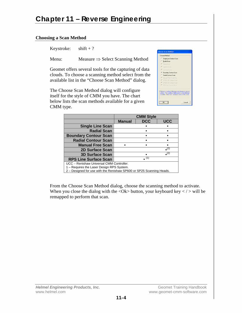
Chapter 11 – Reverse Engineering
Helmel Engineering Products, Inc. Geomet Training Handbookwww.helmel.com www.geomet-cmm-software.com
11-4
Choosing a Scan Method
Keystroke: shift + ?
Menu: Measure ⇒ Select Scanning Method
Geomet offers several tools for the capturing of dataclouds. To choose a scanning method select from theavailable list in the “Choose Scan Method” dialog.
The Choose Scan Method dialog will configureitself for the style of CMM you have. The chartbelow lists the scan methods available for a givenCMM type.
CMM StyleManual DCC UCC
Single Line Scan • •Radial Scan • •
Boundary Contour Scan • •Radial Contour Scan • •
Manual Free Scan • • •2D Surface Scan •(2)
3D Surface Scan • •(2)
RPS Line Surface Scan • (1)
UCC – Renishaw Universal CMM Controller.1 – Requires the Laser Design RPS System.2 – Designed for use with the Renishaw SP600 or SP25 Scanning Heads.
From the Choose Scan Method dialog, choose the scanning method to activate.When you close the dialog with the <Ok> button, your keyboard key < / > will beremapped to perform that scan.

Chapter 11 – Reverse Engineering
Helmel Engineering Products, Inc. Geomet Training Handbookwww.helmel.com www.geomet-cmm-software.com
11-5
Manual Free Scan
Keystroke: /
Menu: Measure ⇒ Perform Selected Scan
This method requires the operator to perform the actual capturing of data. It canbe used with manual or DCC CMMs. On DCC systems, the Motors must bedisabled.
Capturing a Data Cloud
The operator manually captures data points by making contact with the surface.Points are entered either using an electronic touch probe, or depressing the footswitch when using hard probes. The XYZ recorded data represents the ball centerof the stylus.
Controlling the Data Cloud
This method does not produce a controlled capture of data. It relies on theoperator to capture the data cloud in some uniform procedure. If capturing with amanual CMM, it is helpful to lock an axis, such as the x-axis, and capture datapoints moving in the Y direction. Then unlock the X-axis and reposition to a newX location and repeat the process to create a new column of data.
Creating columns of data points will be easier to manipulate by a CAD system ifit is required to build a surface.
When sufficient data points have been captured, press the < F5 > function key torecord the data points.
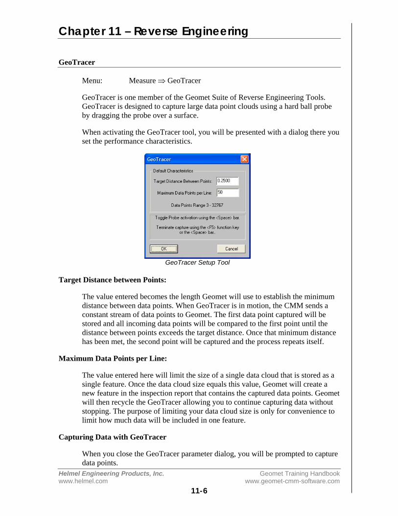
Chapter 11 – Reverse Engineering
Helmel Engineering Products, Inc. Geomet Training Handbookwww.helmel.com www.geomet-cmm-software.com
11-6
GeoTracer
Menu: Measure ⇒ GeoTracer
GeoTracer is one member of the Geomet Suite of Reverse Engineering Tools.GeoTracer is designed to capture large data point clouds using a hard ball probeby dragging the probe over a surface.
When activating the GeoTracer tool, you will be presented with a dialog there youset the performance characteristics.
GeoTracer Setup Tool
Target Distance between Points:
The value entered becomes the length Geomet will use to establish the minimumdistance between data points. When GeoTracer is in motion, the CMM sends aconstant stream of data points to Geomet. The first data point captured will bestored and all incoming data points will be compared to the first point until thedistance between points exceeds the target distance. Once that minimum distancehas been met, the second point will be captured and the process repeats itself.
Maximum Data Points per Line:
The value entered here will limit the size of a single data cloud that is stored as asingle feature. Once the data cloud size equals this value, Geomet will create anew feature in the inspection report that contains the captured data points. Geometwill then recycle the GeoTracer allowing you to continue capturing data withoutstopping. The purpose of limiting your data cloud size is only for convenience tolimit how much data will be included in one feature.
Capturing Data with GeoTracer
When you close the GeoTracer parameter dialog, you will be prompted to capturedata points.

Chapter 11 – Reverse Engineering
Helmel Engineering Products, Inc. Geomet Training Handbookwww.helmel.com www.geomet-cmm-software.com
11-7
GeoTracer Probe Disabled Prompt
When the prompt appears, the capturing of the data points is suspended allowingyou time to move the CMM into position on your part. This is indicated by the*** Probe Disabled *** statement next to the Current Status prompt.
When you are ready to capture data, press the <space bar>, or depress the optionalfoot switch. Geomet will now capture data when you start moving your probeacross the part. Pressing the space bar again will cause Geomet to return to aDisabled Probe state and create a feature with the captured data points.
Capturing Data with GeoTracer on DCC style CMMs
The GeoTracer tool can be used on DCC style CMMs as long as you disable themotion drive system. To disable the motion drive system within Geomet, activatethe System Options <F9>, locate the “Enhanced Feature” page and remove thecheck from “Enable DCC Motors”.
The Captured Data Cloud
The data points being captured will be the XYZ location of the probe ball center.Since probes do not offer vector feedback informing the host measuring softwarewhere the contact point was on the ball, a determination of surface points is notpossible. This condition can be corrected by exporting the data clouds to most ofthe popular CAD software systems and then constructing a surface followed byoffsetting that surface by the probe radius.
Useful Tips
If your intent is to take the data clouds and export them to a CAD system, it ishelpful to organize how you capture the data clouds. Most manual CMMs offerlocking mechanisms on the X, Y and Z-axes. This allows you to lock one axis anddrag the probe over your part to form a single line of data points. When you reachthe end of your captured data point line, press the <space bar>, this will create afeature in the inspection report. Next, remove the lock and move to a new locationand reset the lock repeating the drag operation to create a parallel set of datapoints.
Performance Considerations using GeoTracer
The quality of the data points can be affected by the speed of the CMM whilecapturing the data points. A CMM interface captures the XYZ scale values basedon a timed cycle. Some interfaces cycle 30 times or more per second, such as the

Chapter 11 – Reverse Engineering
Helmel Engineering Products, Inc. Geomet Training Handbookwww.helmel.com www.geomet-cmm-software.com
11-8
Helmel ProCounter series. At this cycle speed you will capture a consistent set ofdata points while dragging your hard probe at normal speeds between 2" (51mm)and 5" (127mm) per second which translates to capturing approximately 20-50points per second.
If your CMM interface cycles at a lower rate, such as most interfaces on DirectComputer Control (DCC) CMMs, the cycle can be slowed down to as little as 3cycles per second. On this style CMM the actual reading of the XYZ scales isperformed by the motion controller and forwarded to the host measuring softwareas a status update. At the slower cycle rate, the drag speed required to produce auniform set of data points must be reduced to speeds around 1" (25mm) persecond.
Should the drag speed be too fast the spread between data points will be greaterthan the requested distance set in the GeoTracer Parameters. If you findundesirable results in the spread of your data points, slow down the drag speed.
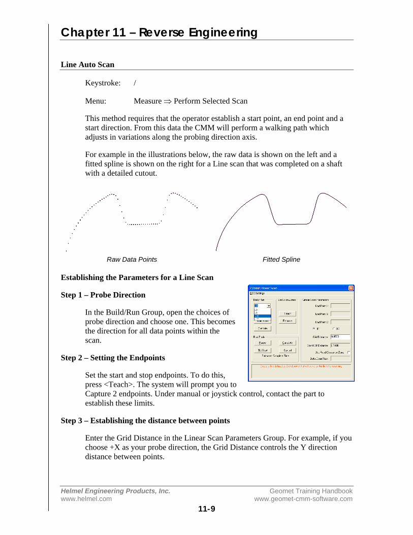
Chapter 11 – Reverse Engineering
Helmel Engineering Products, Inc. Geomet Training Handbookwww.helmel.com www.geomet-cmm-software.com
11-9
Line Auto Scan
Keystroke: /
Menu: Measure ⇒ Perform Selected Scan
This method requires that the operator establish a start point, an end point and astart direction. From this data the CMM will perform a walking path whichadjusts in variations along the probing direction axis.
For example in the illustrations below, the raw data is shown on the left and afitted spline is shown on the right for a Line scan that was completed on a shaftwith a detailed cutout.
Raw Data Points Fitted Spline
Establishing the Parameters for a Line Scan
Step 1 – Probe Direction
In the Build/Run Group, open the choices ofprobe direction and choose one. This becomesthe direction for all data points within thescan.
Step 2 – Setting the Endpoints
Set the start and stop endpoints. To do this,press <Teach>. The system will prompt you toCapture 2 endpoints. Under manual or joystick control, contact the part toestablish these limits.
Step 3 – Establishing the distance between points
Enter the Grid Distance in the Linear Scan Parameters Group. For example, if youchoose +X as your probe direction, the Grid Distance controls the Y directiondistance between points.
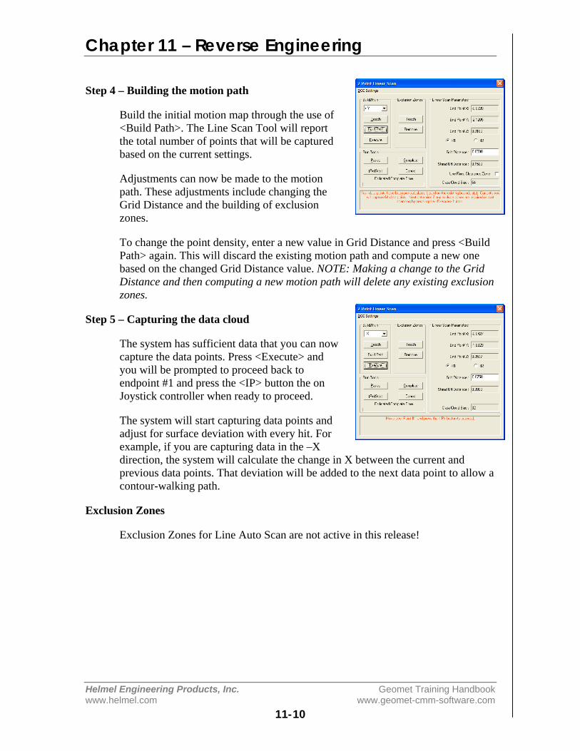
Chapter 11 – Reverse Engineering
Helmel Engineering Products, Inc. Geomet Training Handbookwww.helmel.com www.geomet-cmm-software.com
11-10
Step 4 – Building the motion path
Build the initial motion map through the use of<Build Path>. The Line Scan Tool will reportthe total number of points that will be capturedbased on the current settings.
Adjustments can now be made to the motionpath. These adjustments include changing theGrid Distance and the building of exclusionzones.
To change the point density, enter a new value in Grid Distance and press <BuildPath> again. This will discard the existing motion path and compute a new onebased on the changed Grid Distance value. NOTE: Making a change to the GridDistance and then computing a new motion path will delete any existing exclusionzones.
Step 5 – Capturing the data cloud
The system has sufficient data that you can nowcapture the data points. Press <Execute> andyou will be prompted to proceed back toendpoint #1 and press the <IP> button the onJoystick controller when ready to proceed.
The system will start capturing data points andadjust for surface deviation with every hit. Forexample, if you are capturing data in the –Xdirection, the system will calculate the change in X between the current andprevious data points. That deviation will be added to the next data point to allow acontour-walking path.
Exclusion Zones
Exclusion Zones for Line Auto Scan are not active in this release!

Chapter 11 – Reverse Engineering
Helmel Engineering Products, Inc. Geomet Training Handbookwww.helmel.com www.geomet-cmm-software.com
11-11
4 Point Boundary Surface Scan
Keystroke: /
Menu: Measure ⇒ Perform Selected Scan
The Boundary Surface Scan Tool is designed tocapture uniform row and column conforming datapoint clouds while probing in the –Z direction. TheScan Tool will “walk” the surface adjusting its Zprobing height between data points allowing dataclouds to be built on complex surfaces.
To enhance the scan capabilities, exclusion zonescan be added which will direct the motion pathgenerator to eliminate data points over areas you wish excluded from the surface.
Step 1 - Defining the boundary of the scan area
The Boundary Surface Scan Tool defines the boundary of the scan area as havingfour straight sides, shown here are some examples:
Acceptable Acceptable Acceptable Not Acceptable
The shape of the enclosed area is flexible, howeverthere is one rule the shape must follow. Thatexample can be seen in the right image where oneend point is inside a straight line drawn between itsadjoining corners. The Boundary Surface ScanTool will test for this condition and prompt you tocorrect it.
To begin the capture process, press the <Teach>button. You will be prompted to capture the 4 datapoints. Upon completion, you will see the prompt
“The Boundary definitions have been established. To continue, press <BuildPath>.”

Chapter 11 – Reverse Engineering
Helmel Engineering Products, Inc. Geomet Training Handbookwww.helmel.com www.geomet-cmm-software.com
11-12
Step 2 – Establishing the grid density
Ensure the Grid Distance value has the properdata point density value you want to scan. ThisGrid Distance is the distance between columnsand rows.
Step 3 – Building the Motion Path
Build the initial motion map through the use of<Build Path>. The Scan Tool will report thetotal number of points that will be capturedbased on the current settings.
Adjustments can now be made to the motion path. These adjustments includechanging the Grid Distance and the building of exclusion zones.
To change the point density, enter a new value in Grid Distance and press <BuildPath> again. This will discard the existing motion path and compute a new onebased on the changed Grid Distance value. NOTE: Making a change to the GridDistance and then computing a new motion path will delete any existing exclusionzones.
Step 4 – Exclusion Zones
One very important feature of the Scan Tool is the ability to eliminate areaswithin the defined scan boundaries. A common example might be a hole throughthe surface you are scanning. There are two types of Exclusion Zones available.
Diameter Exclusion Zone: This tool workswell to define exclusion zones around holes.Building a zone starts by pressing the <TeachDia> button which prompts you to capture datapoints around the area to exclude.
When you have captured sufficient points, pressthe terminate key, <F5>. The scan tool willcalculate the exclude area and determine thenumber of data points that will be excluded.Press <Remove> to complete the exclusion.
Confirm Removal of Data Points
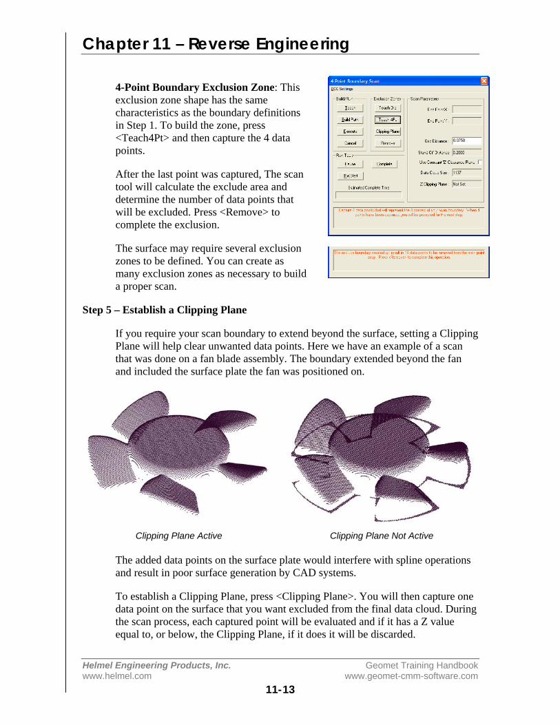
Chapter 11 – Reverse Engineering
Helmel Engineering Products, Inc. Geomet Training Handbookwww.helmel.com www.geomet-cmm-software.com
11-13
4-Point Boundary Exclusion Zone: Thisexclusion zone shape has the samecharacteristics as the boundary definitionsin Step 1. To build the zone, press<Teach4Pt> and then capture the 4 datapoints.
After the last point was captured, The scantool will calculate the exclude area anddetermine the number of data points thatwill be excluded. Press <Remove> tocomplete the exclusion.
The surface may require several exclusionzones to be defined. You can create asmany exclusion zones as necessary to builda proper scan.
Step 5 – Establish a Clipping Plane
If you require your scan boundary to extend beyond the surface, setting a ClippingPlane will help clear unwanted data points. Here we have an example of a scanthat was done on a fan blade assembly. The boundary extended beyond the fanand included the surface plate the fan was positioned on.
Clipping Plane Active Clipping Plane Not Active
The added data points on the surface plate would interfere with spline operationsand result in poor surface generation by CAD systems.
To establish a Clipping Plane, press <Clipping Plane>. You will then capture onedata point on the surface that you want excluded from the final data cloud. Duringthe scan process, each captured point will be evaluated and if it has a Z valueequal to, or below, the Clipping Plane, if it does it will be discarded.
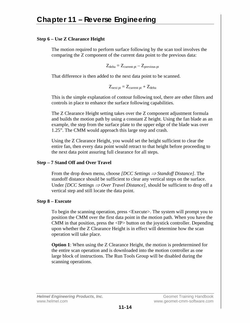
Chapter 11 – Reverse Engineering
Helmel Engineering Products, Inc. Geomet Training Handbookwww.helmel.com www.geomet-cmm-software.com
11-14
Step 6 – Use Z Clearance Height
The motion required to perform surface following by the scan tool involves thecomparing the Z component of the current data point to the previous data:
Zdelta = Zcurrent pt – Zprevious pt
That difference is then added to the next data point to be scanned.
Znext pt = Zcurrent pt + Zdelta
This is the simple explanation of contour following tool, there are other filters andcontrols in place to enhance the surface following capabilities.
The Z Clearance Height setting takes over the Z component adjustment formulaand builds the motion path by using a constant Z height. Using the fan blade as anexample, the step from the surface plate to the upper edge of the blade was over1.25”. The CMM would approach this large step and crash.
Using the Z Clearance Height, you would set the height sufficient to clear theentire fan, then every data point would retract to that height before proceeding tothe next data point assuring full clearance for all steps.
Step – 7 Stand Off and Over Travel
From the drop down menu, choose [DCC Settings ⇒ Standoff Distance]. Thestandoff distance should be sufficient to clear any vertical steps on the surface.Under [DCC Settings ⇒ Over Travel Distance], should be sufficient to drop off avertical step and still locate the data point.
Step 8 – Execute
To begin the scanning operation, press <Execute>. The system will prompt you toposition the CMM over the first data point in the motion path. When you have theCMM in that position, press the <IP> button on the joystick controller. Dependingupon whether the Z Clearance Height is in effect will determine how the scanoperation will take place.
Option 1: When using the Z Clearance Height, the motion is predetermined forthe entire scan operation and is downloaded into the motion controller as onelarge block of instructions. The Run Tools Group will be disabled during thescanning operations.
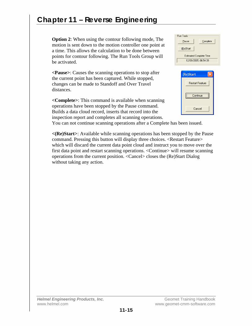
Chapter 11 – Reverse Engineering
Helmel Engineering Products, Inc. Geomet Training Handbookwww.helmel.com www.geomet-cmm-software.com
11-15
Option 2: When using the contour following mode, Themotion is sent down to the motion controller one point ata time. This allows the calculation to be done betweenpoints for contour following. The Run Tools Group willbe activated.
<Pause>: Causes the scanning operations to stop afterthe current point has been captured. While stopped,changes can be made to Standoff and Over Traveldistances.
<Complete>: This command is available when scanningoperations have been stopped by the Pause command.Builds a data cloud record, inserts that record into theinspection report and completes all scanning operations.You can not continue scanning operations after a Complete has been issued.
<(Re)Start>: Available while scanning operations has been stopped by the Pausecommand. Pressing this button will display three choices. <Restart Feature>which will discard the current data point cloud and instruct you to move over thefirst data point and restart scanning operations. <Continue> will resume scanningoperations from the current position. <Cancel> closes the (Re)Start Dialogwithout taking any action.
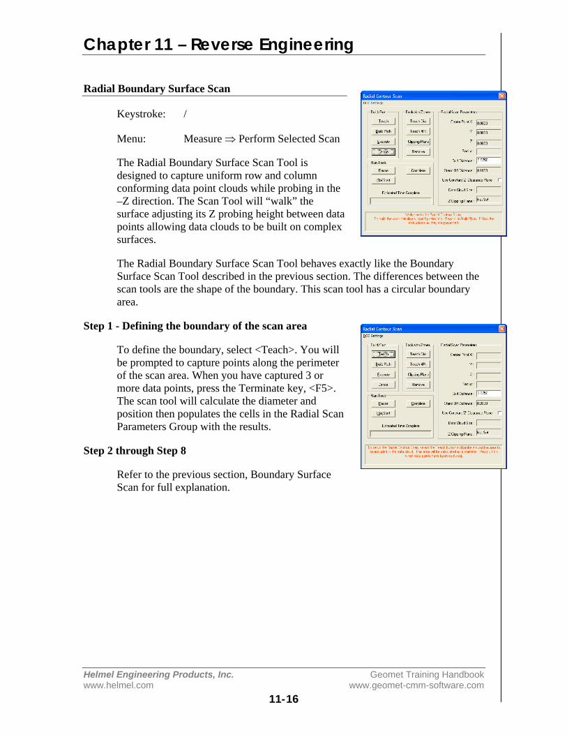
Chapter 11 – Reverse Engineering
Helmel Engineering Products, Inc. Geomet Training Handbookwww.helmel.com www.geomet-cmm-software.com
11-16
Radial Boundary Surface Scan
Keystroke: /
Menu: Measure ⇒ Perform Selected Scan
The Radial Boundary Surface Scan Tool isdesigned to capture uniform row and columnconforming data point clouds while probing in the–Z direction. The Scan Tool will “walk” thesurface adjusting its Z probing height between datapoints allowing data clouds to be built on complexsurfaces.
The Radial Boundary Surface Scan Tool behaves exactly like the BoundarySurface Scan Tool described in the previous section. The differences between thescan tools are the shape of the boundary. This scan tool has a circular boundaryarea.
Step 1 - Defining the boundary of the scan area
To define the boundary, select <Teach>. You willbe prompted to capture points along the perimeterof the scan area. When you have captured 3 ormore data points, press the Terminate key, <F5>.The scan tool will calculate the diameter andposition then populates the cells in the Radial ScanParameters Group with the results.
Step 2 through Step 8
Refer to the previous section, Boundary SurfaceScan for full explanation.
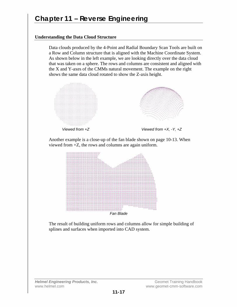
Chapter 11 – Reverse Engineering
Helmel Engineering Products, Inc. Geomet Training Handbookwww.helmel.com www.geomet-cmm-software.com
11-17
Understanding the Data Cloud Structure
Data clouds produced by the 4-Point and Radial Boundary Scan Tools are built ona Row and Column structure that is aligned with the Machine Coordinate System.As shown below in the left example, we are looking directly over the data cloudthat was taken on a sphere. The rows and columns are consistent and aligned withthe X and Y-axes of the CMMs natural movement. The example on the rightshows the same data cloud rotated to show the Z-axis height.
Viewed from +Z Viewed from +X, -Y, +Z
Another example is a close-up of the fan blade shown on page 10-13. Whenviewed from +Z, the rows and columns are again uniform.
Fan Blade
The result of building uniform rows and columns allow for simple building ofsplines and surfaces when imported into CAD system.

Chapter 11 – Reverse Engineering
Helmel Engineering Products, Inc. Geomet Training Handbookwww.helmel.com www.geomet-cmm-software.com
11-18
Cardinal Spline
A cardinal spline is a series ofindividual curves between pointsjoined to form a larger curve. Thespline is specified by an array ofpoints and a tension parameter. Acardinal spline passes smoothlythrough each point in the array; thereare no sharp corners and no abruptchanges in the tightness of the curve.By passing through every point, thereare no missed points that can causeerrors when fitting a surface over thesplines.
The tension of a cardinal splinedetermines the fitting of each curvesection in regards to the data points.The range for the tension value is 0.0to 1.0 where 1.0 would deliverstraight lines between the data pointsand 0.0 would produce the mostflexible curves fitted through eachdata point.
Starting the Cardinal Spline Tool
The Cardinal Spline feature works on data clouds captured through the variousscanning methods available in Geomet. To activate the feature, locate the datacloud feature in the inspection report and highlight it using the left click of themouse. Then right click to bring up the sub menu. Locate [Cardinal Spline] in thelist and click on it.
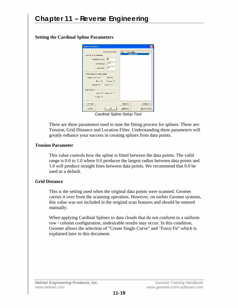
Chapter 11 – Reverse Engineering
Helmel Engineering Products, Inc. Geomet Training Handbookwww.helmel.com www.geomet-cmm-software.com
11-19
Setting the Cardinal Spline Parameters
Cardinal Spline Setup Tool
There are three parameters used to tune the fitting process for splines. These are:Tension, Grid Distance and Location Filter. Understanding these parameters willgreatly enhance your success in creating splines from data points.
Tension Parameter
This value controls how the spline is fitted between the data points. The validrange is 0.0 to 1.0 where 0.0 produces the largest radius between data points and1.0 will produce straight lines between data points. We recommend that 0.0 beused as a default.
Grid Distance
This is the setting used when the original data points were scanned. Geometcarries it over from the scanning operation. However, on earlier Geomet systems,this value was not included in the original scan features and should be enteredmanually.
When applying Cardinal Splines to data clouds that do not conform to a uniformrow / column configuration, undesirable results may occur. In this condition,Geomet allows the selection of "Create Single Curve" and "Force Fit" which isexplained later in this document.
Chapter 11 – Reverse Engineering
Helmel Engineering Products, Inc. Geomet Training Handbookwww.helmel.com www.geomet-cmm-software.com
11-20
Location Filter
Geomet starts building rows and columns first by sorting the data points into rowand column order. The location filter is applied when Geomet moves down acolumn and ‘looks’ for the next data point. For example: if the column has a startpoint with a "Y" value of 1.000", it would look down the column and expect tofind the next point also with a "Y" value near 1.000". Since scanning operationsdo not deliver exact position, the data point under the start point might have a "Y"value of 1.012". The Location Filter is a factor of the grid distance where 0.15would yield a search zone of 0.15 * Grid Distance (0.15 * 0.05 = .0075). Thisvalue determines the zone around the original "Y" value of 1.000" and the columnsorting would not include the next point at 1.012.
In data clouds that have well-defined row and column structures, the LocationFilter can be low, such as 0.25. In poorly defined patterns, use a value between0.5 and 0.9.
When the value is set too high, the splines created can "jump" to neighboringpoints from other columns.
Spline Fitting and Display Options
Under the group designated as "Spline Fitting and Display Options", you canestablish the spline methodology and fitting behaviors.
Create Single Curve
This option will take all your data points without regard to rows and columns andfit the curves through each point in the same order as the points were captured.This option is designed to work with data points captured with GeoTracer whereyou capture data points in a line with distinct start and finish end points. Whenthis option is checked, the display and export of one spline for this feature willoccur.
Rows / Columns
Row and Column selections are available when Single Selection is not chosen.They are designed to work with data points gathered under the automatic scanningtools in Geomet. These scanning tools capture the data points in organized Rowand Column formations that can be extracted to deliver uniform splines. Whenselecting Row and/or Columns, Geomet will attempt to build straight lines in theXY plane of the captured data points. Then rows and columns are extracted andused to form the splines. It is important that these rows and columns are organizedin controlled positions. See Setup Parameters above.
Chapter 11 – Reverse Engineering
Helmel Engineering Products, Inc. Geomet Training Handbookwww.helmel.com www.geomet-cmm-software.com
11-21
Force Fit
This option is used when Rows and Columns are active. When calculating, somedata points might be skipped if they do not fall within the parameter settings. Thiscan cause a row to contain 2 or more splines. When selecting Force Fit, all datapoints identified in the row or column will be used to fit one spline. Another usefor Force Fit is when there were exclusion zones used in data point scanning. Thiswill fit the spline over the exclusion zone.
Closed Path
When this option is checked, Geomet will attempt to close the path from the lastdata point to the first.
Data Point
When selected, this option will display the complete set of data points in additionto any splines selected for showing.
Export Options
These options, combined with Spline Fitting and Display Options control theexport characteristics. The selections of Row and Column for export are availablewhen Create Single Curve is NOT selected. NOTE: selecting Row and Columnsin the Display group does not automatically create exported rows andcolumns!
NOTE: Cardinal Splines is exported in the IGES format only!
Rows
This selection will create and export splines derived from the data points thatconform to rows. The rows exported are controlled by the selections of Force Fitand Closed Path.
Columns
This selection will create and export splines derived from the data points thatconform to columns. The columns exported are controlled by the selections ofForce Fit and Closed Path.
Data Points
This selection will export the data cloud in addition to any row and columnselection already made.

Chapter 11 – Reverse Engineering
Helmel Engineering Products, Inc. Geomet Training Handbookwww.helmel.com www.geomet-cmm-software.com
11-22
Executing the Cardinal Spline
Once the parameters have been set, highlight from the list of data clouds thefeatures you want the Cardinal Spline function to work with. Process the requestby press <Ok> to build the Cardinal Splines.
Captured Data Points Fitted Cardinal Splines
The illustration above shows the application of Cardinal Spline to a raw set ofdata points that have been captured with Radial Boundary Contour using a gridspacing of 0.020".
Removing Cardinal Splines
To remove the Cardinal Splines from a feature, highlight the feature and press the<Remove Spline> button.

Chapter 11 – Reverse Engineering
Helmel Engineering Products, Inc. Geomet Training Handbookwww.helmel.com www.geomet-cmm-software.com
11-23
Exporting
Menu: File ⇒ Export ⇒ Export
Geomet can export features and data points in three formats.
ASCII and DXF: Exports data point clouds and 3D Point entities. On features,such as a circle, only the data points used to calculate the feature would beexported.
IGES: This format exports all features based on the following table.
Summary of IGES Supported FeaturesType Definition100 Circular Arc Entity104 Conic Arc Entity108 Plane Entity110 Line Entity116 Point Entity126 Rational B-Spline Curve Entity128 Rational B-Spline Surface Entity144 Trimmed (Parameteric) Surface Entity158 Sphere Entity190 Plane Surface Entity196 Spherical Surface Entity504 Edge Entity508 Loop Entity510 Face Entity
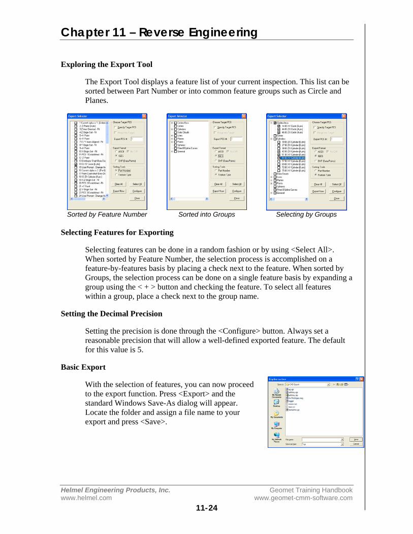
Chapter 11 – Reverse Engineering
Helmel Engineering Products, Inc. Geomet Training Handbookwww.helmel.com www.geomet-cmm-software.com
11-24
Exploring the Export Tool
The Export Tool displays a feature list of your current inspection. This list can besorted between Part Number or into common feature groups such as Circle andPlanes.
Sorted by Feature Number Sorted into Groups Selecting by Groups
Selecting Features for Exporting
Selecting features can be done in a random fashion or by using <Select All>.When sorted by Feature Number, the selection process is accomplished on afeature-by-features basis by placing a check next to the feature. When sorted byGroups, the selection process can be done on a single feature basis by expanding agroup using the < + > button and checking the feature. To select all featureswithin a group, place a check next to the group name.
Setting the Decimal Precision
Setting the precision is done through the <Configure> button. Always set areasonable precision that will allow a well-defined exported feature. The defaultfor this value is 5.
Basic Export
With the selection of features, you can now proceedto the export function. Press <Export> and thestandard Windows Save-As dialog will appear.Locate the folder and assign a file name to yourexport and press <Save>.
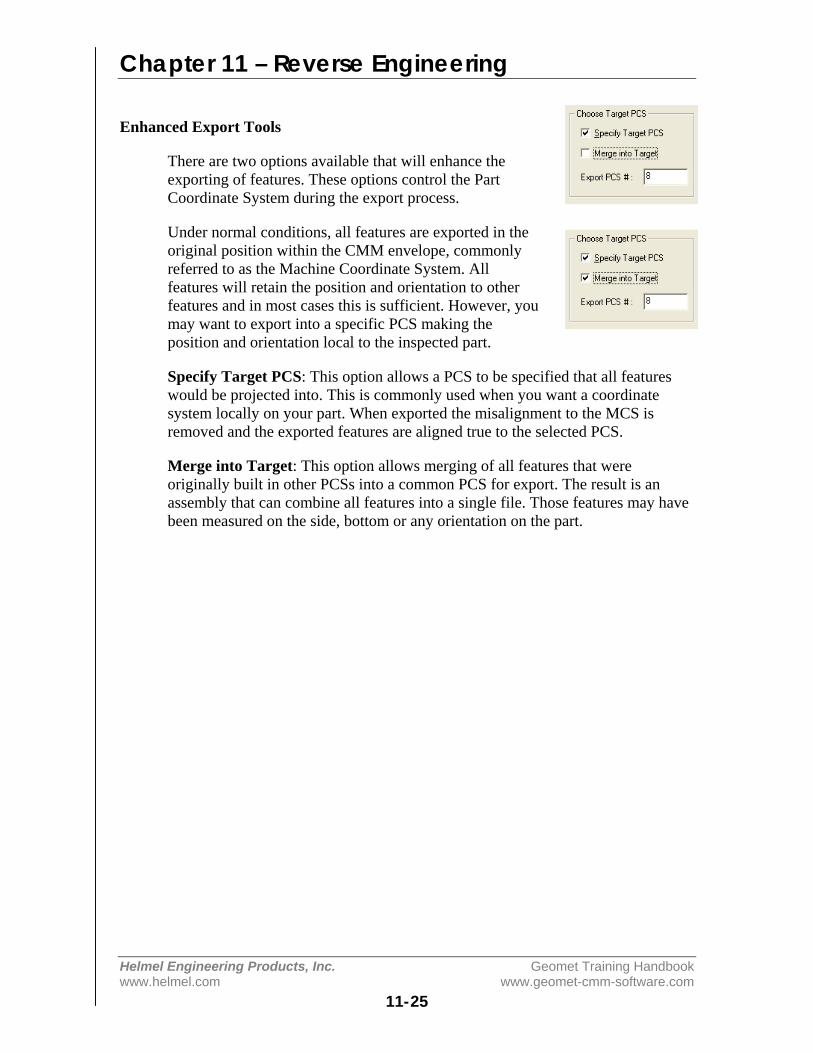
Chapter 11 – Reverse Engineering
Helmel Engineering Products, Inc. Geomet Training Handbookwww.helmel.com www.geomet-cmm-software.com
11-25
Enhanced Export Tools
There are two options available that will enhance theexporting of features. These options control the PartCoordinate System during the export process.
Under normal conditions, all features are exported in theoriginal position within the CMM envelope, commonlyreferred to as the Machine Coordinate System. Allfeatures will retain the position and orientation to otherfeatures and in most cases this is sufficient. However, youmay want to export into a specific PCS making theposition and orientation local to the inspected part.
Specify Target PCS: This option allows a PCS to be specified that all featureswould be projected into. This is commonly used when you want a coordinatesystem locally on your part. When exported the misalignment to the MCS isremoved and the exported features are aligned true to the selected PCS.
Merge into Target: This option allows merging of all features that wereoriginally built in other PCSs into a common PCS for export. The result is anassembly that can combine all features into a single file. Those features may havebeen measured on the side, bottom or any orientation on the part.


Appendix 1 – Technical Notes
Helmel Engineering Products, Inc. Geomet Training Handbookwww.helmel.com www.geomet-cmm-software.com
App 1-1
Technical Notes
Curved Surface Measurement with Vector Point .................... App 1 - 2
Multi-Point Feature and CMM Inherent Errors ....................... App 1 - 9
Appendix 1 – Technical Notes
Helmel Engineering Products, Inc. Geomet Training Handbookwww.helmel.com www.geomet-cmm-software.com
App 1-2
Curved Surface Measurement with Vector Point:
Applies to: Geomet 101 with GeoPlus, Geomet 301, GeoCAD.Last updated: Friday January 07, 2005.
NOTICEInformation contained within this document is subject to change without notice.No part of this document may be reproduced or transmitted in any form or by anymeans, electronic or mechanical, for any purpose without written authorizationfrom Helmel Engineering Products, Inc.
This document contains proprietary subject matter of Helmel EngineeringProducts, Inc. and its receipt or possession does not convey any rights toreproduce disclose its content or to manufacture, use or sell anything it maydescribe. Reproduction, disclosure or use without specific written authorization ofHelmel Engineering Products, Inc. is strictly forbidden.
© Helmel Engineering Products, Inc. 1985 - 2006. All right reserved.
GEOMET®, MICROSTAR® are trademarks ofHelmel Engineering Products, Inc.
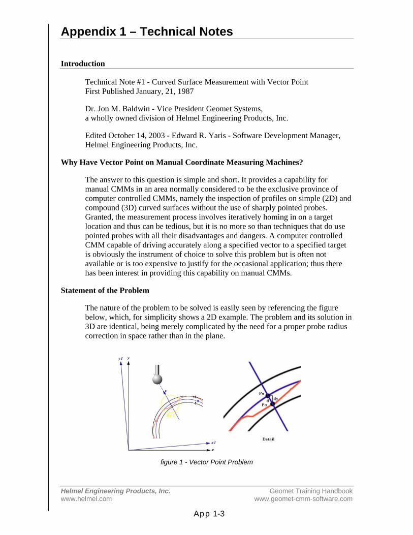
Appendix 1 – Technical Notes
Helmel Engineering Products, Inc. Geomet Training Handbookwww.helmel.com www.geomet-cmm-software.com
App 1-3
Introduction
Technical Note #1 - Curved Surface Measurement with Vector PointFirst Published January, 21, 1987
Dr. Jon M. Baldwin - Vice President Geomet Systems,a wholly owned division of Helmel Engineering Products, Inc.
Edited October 14, 2003 - Edward R. Yaris - Software Development Manager,Helmel Engineering Products, Inc.
Why Have Vector Point on Manual Coordinate Measuring Machines?
The answer to this question is simple and short. It provides a capability formanual CMMs in an area normally considered to be the exclusive province ofcomputer controlled CMMs, namely the inspection of profiles on simple (2D) andcompound (3D) curved surfaces without the use of sharply pointed probes.Granted, the measurement process involves iteratively homing in on a targetlocation and thus can be tedious, but it is no more so than techniques that do usepointed probes with all their disadvantages and dangers. A computer controlledCMM capable of driving accurately along a specified vector to a specified targetis obviously the instrument of choice to solve this problem but is often notavailable or is too expensive to justify for the occasional application; thus therehas been interest in providing this capability on manual CMMs.
Statement of the Problem
The nature of the problem to be solved is easily seen by referencing the figurebelow, which, for simplicity shows a 2D example. The problem and its solution in3D are identical, being merely complicated by the need for a proper probe radiuscorrection in space rather than in the plane.
figure 1 - Vector Point Problem

Appendix 1 – Technical Notes
Helmel Engineering Products, Inc. Geomet Training Handbookwww.helmel.com www.geomet-cmm-software.com
App 1-4
Shown in the figure is a nominal surface, n, along with the actual part surface, a,and allowed profile limits, +t and –t. We wish to determine, at selected points, thedeviation of the actual surface from the nominal. Two pairs of axes, x and y, ofthe machine coordinate system (MCS) and x1 and y1, of the part coordinatesystem (PCS) are shown. Ideally, we would use a spherical probe and approachthe nominal point to be inspected, Pn, along the nominal normal vector, v.Assuming the probe radius and errors in the actual surface both are smallcompared to the radius of curvature at Pn, the probe would contact the actualsurface at point Pa, also along the normal vector v, the probe center would alsofall along v and the probe radius correction and thus the deviation of the actualsurface from ideality could be simply computed. This is, in fact, what is donewhen one takes this measurement with a computer controlled CMM having vectordrive capability.
We will note in passing that the inspection requirement may call for reportingeither the total deviation, d, along the normal vector or its component, dy, parallelto the part coordinate system (PCS) axis most nearly perpendicular to the surface.This has no effect on the measurement process, but we will return to this matterlater on. We will also note in passing that the first assumption made above,namely that the probe radius is small compared to the radius of curvature of thepart surface, is not particular to the manual CMM problem but applies as well toat least some curved surface measuring algorithms designed for use withmotorized vector drive CMMs.
If we try this same measurement with a manual CMM we find that since theCMM is not easily moved along the specified normal vector with any degree ofaccuracy we have trouble making even the point of contact with the nominalsurface, never mind the point of contact with the actual surface, fall as it should.

Appendix 1 – Technical Notes
Helmel Engineering Products, Inc. Geomet Training Handbookwww.helmel.com www.geomet-cmm-software.com
App 1-5
A Solution to the Problem – Normal Vector Point
figure 2 – Approach Direction figure 3 – Manual CMMThe only axis along which we can accurately drive on a manual CMM is one ofthe MCS axes, see figure 3, so we will begin with that. Since we know the radiusof the measuring probe, it is easy to calculate a two dimensional location in theMCS, to which we can drive the probe and, having locked the CMM axes on thistarget, drive along the third CMM axis such that the first point at which the probecontacts the nominal surface will be Pn.
Referring to figure 2, we are not out of the woods yet. Even if we are successfulin arriving at the desired point Pn on the nominal surface, we find that if theactual surface is not ideal we will miss Pa and so will, in general, report an errorgreater than actually exist. To illustrate, let us assume we have computed a targetpoint on an MCS axis as indicated above. We will generally want to move alongthe MCS axis most nearly perpendicular to the surface and it does not reallymatter how far away from the part we begin. We simply lock two of the machineaxes and approach the part surface along the vector labeled "approach axis",arriving at the nominal location of the surface with the probe center and thenominal contact point, Pn, both lying on the nominal normal vector, v. However,we have yet to contact the actual surface, so we proceed further along theapproach axis until contact is made at point Pa1. Obviously, we have not endedup exactly where we would like to be. We were hoping to get to point Pa and thenthe sought-for-error would have been simply Pa-Pn, but we have missed. Theerror is not anything we could have compensated for ahead of time since it is afunction of the actual surface location, a thing we were totally uninformed aboutuntil just this minute. We now have some, rather limited, knowledge about theactual location of the surface and can use that knowledge to refine our approach.
As a device to evaluate the extent to which we have accomplished the desiredobjective, namely, to arrive at the actual surface with both the probe center andthe contact point on the normal vector, we will introduce the concept of theprobing error. The probing error will be defined as the normal distance from theball center at contact and the nominal normal vector, v, and is shown as e1 for the
Appendix 1 – Technical Notes
Helmel Engineering Products, Inc. Geomet Training Handbookwww.helmel.com www.geomet-cmm-software.com
App 1-6
first probing in Figure 2. We would compare e1 to some predeterminedacceptable value which we will call the probing error limit, e. (In the actualimplementation of vector point, a value for e =(+t + 1 - t1) / 5 is suggested butmay be changed by the user).
If e1 <= e then the attempt to measure the desired target point is considered tohave been successful and the measurement results are printed.
If e1 > e the value of e1 is displayed and the user is given the option to accept theresults or to attempt further refinement of the probing location. The new approachis generated by projecting the current probe center location back onto the nominalnormal vector, v, to get a refined estimate of where we want the probe to be at thetime it contacts the actual surface. The machine axis vector passing through thisnew point becomes the new approach axis, along which a new 2D target iscalculated, and the process is repeated to give a new point of contact, Pa2, andassociated probing error, e2. The process may be repeated indefinitely until eitherthe probing error limit criterion is satisfied or the user decides the disparitybetween the actual and nominal surfaces is so large that the probing error limitwill always be exceeded.
The final contact point, in this case Pa2, is projected onto the normal vector, v,and the distance, da2, along v from Pn to Pa2 is taken as the final estimate of thenormal deviation of the surface from its ideal location.
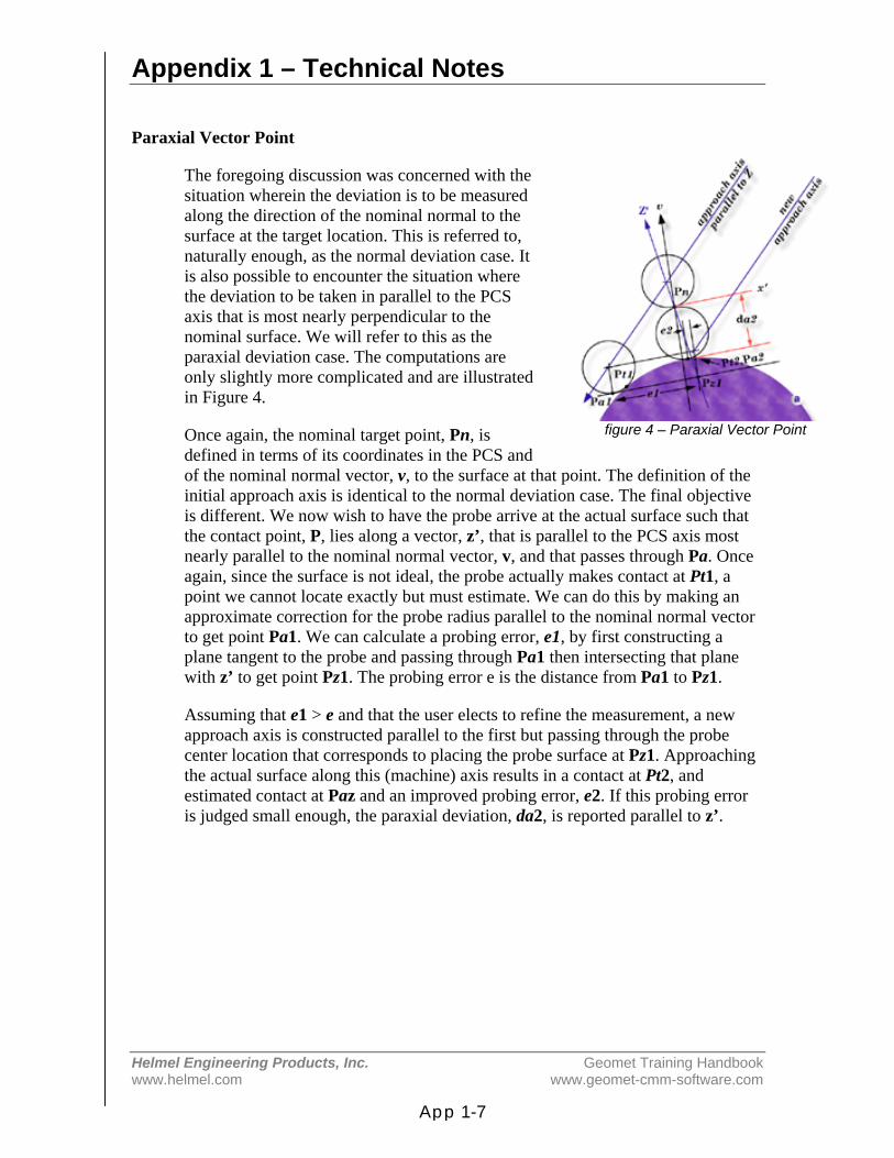
Appendix 1 – Technical Notes
Helmel Engineering Products, Inc. Geomet Training Handbookwww.helmel.com www.geomet-cmm-software.com
App 1-7
Paraxial Vector Point
The foregoing discussion was concerned with thesituation wherein the deviation is to be measuredalong the direction of the nominal normal to thesurface at the target location. This is referred to,naturally enough, as the normal deviation case. Itis also possible to encounter the situation wherethe deviation to be taken in parallel to the PCSaxis that is most nearly perpendicular to thenominal surface. We will refer to this as theparaxial deviation case. The computations areonly slightly more complicated and are illustratedin Figure 4.
Once again, the nominal target point, Pn, isdefined in terms of its coordinates in the PCS andof the nominal normal vector, v, to the surface at that point. The definition of theinitial approach axis is identical to the normal deviation case. The final objectiveis different. We now wish to have the probe arrive at the actual surface such thatthe contact point, P, lies along a vector, z’, that is parallel to the PCS axis mostnearly parallel to the nominal normal vector, v, and that passes through Pa. Onceagain, since the surface is not ideal, the probe actually makes contact at Pt1, apoint we cannot locate exactly but must estimate. We can do this by making anapproximate correction for the probe radius parallel to the nominal normal vectorto get point Pa1. We can calculate a probing error, e1, by first constructing aplane tangent to the probe and passing through Pa1 then intersecting that planewith z’ to get point Pz1. The probing error e is the distance from Pa1 to Pz1.
Assuming that e1 > e and that the user elects to refine the measurement, a newapproach axis is constructed parallel to the first but passing through the probecenter location that corresponds to placing the probe surface at Pz1. Approachingthe actual surface along this (machine) axis results in a contact at Pt2, andestimated contact at Paz and an improved probing error, e2. If this probing erroris judged small enough, the paraxial deviation, da2, is reported parallel to z’.
figure 4 – Paraxial Vector Point

Appendix 1 – Technical Notes
Helmel Engineering Products, Inc. Geomet Training Handbookwww.helmel.com www.geomet-cmm-software.com
App 1-8
Experimenting with Vector Point
Before you get too serious about using vector point in a real application, it may behelpful to you to play with it a bit. One easy way to do this is to use the referencesample files found in the Geomet web site at:
http://www.geomet-cmm-software.com
Navigate by following the links:
Knowledgebase ⇒ Measured Features ⇒ Point
Choose Vector Point from the Feature Measurement Point Types. Following thatlink, choose Method 5 – Vector Point Import. There are several examples tofollow to help in understanding the application of Vector Points on DCC andmanual style CMMs.

Appendix 1 – Technical Notes
Helmel Engineering Products, Inc. Geomet Training Handbookwww.helmel.com www.geomet-cmm-software.com
App 1-9
Multi-Point Feature and CMM Inherent Errors:
Applies to: All Levels of GeometLast updated: Monday December 13, 2005.
NOTICEInformation contained within this document is subject to change without notice.No part of this document may be reproduced or transmitted in any form or by anymeans, electronic or mechanical, for any purpose without written authorizationfrom Helmel Engineering Products, Inc.
This document contains proprietary subject matter of Helmel EngineeringProducts, Inc. and its receipt or possession does not convey any rights toreproduce disclose its content or to manufacture, use or sell anything it maydescribe. Reproduction, disclosure or use without specific written authorization ofHelmel Engineering Products, Inc. is strictly forbidden.
© Helmel Engineering Products, Inc. 1985 - 2006. All right reserved.
GEOMET®, MICROSTAR® are trademarks ofHelmel Engineering Products, Inc.
Appendix 1 – Technical Notes
Helmel Engineering Products, Inc. Geomet Training Handbookwww.helmel.com www.geomet-cmm-software.com
App 1-10
Introduction
Technical Note #2 - Multi-Point Feature Inherent ErrorsPublished October, 14, 2003
Edward R. Yaris - Software Development Manager,Helmel Engineering Products, Inc.
Commonly found Errors
• CMM Calibration Errors• Probing Errors• Operator Influences• Data Point Spread
System Errors
In all multi-point features, the ability to report accurate and repeatable results aresubject to the quality of the gathered data points. Influencing your measuredresults will be the stacking of inaccuracies within your measuring systemgenerated by the commonly found errors listed above.
Coordinate Measuring Machine
Scale ErrorThe CMM has inherent inaccuracies such as axial linear error and mechanicallimitations on squareness, parallelism and perpendicularity. Every CMM has ascale attached to each axis of movement. This scale can be a mechanical / opticalor laser configuration. In the case of a mechanical / optical there exists positioningerror which CMM manufacturers will attempt to compensate for throughhardware or software.
For example when a scale is installed, it will be compared to a master scale orlaser. The CMM will be positioned along the scale at different points and thereported position will be compared to the master. If the position reported by thelaser was 10.00000 and the CMM reported 9.99875 The difference will be thelinear inaccuracies of the scale at that position. In a single linear compensation, ascale factor will be applied to the CMM’s position feedback to correct for theerror. However, this method of compensation works with the overall average anddoes not correct for local inaccuracies along the scale.
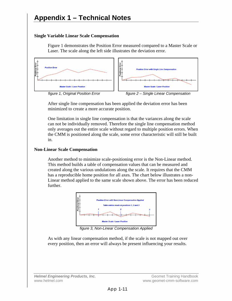
Appendix 1 – Technical Notes
Helmel Engineering Products, Inc. Geomet Training Handbookwww.helmel.com www.geomet-cmm-software.com
App 1-11
Single Variable Linear Scale Compensation
Figure 1 demonstrates the Position Error measured compared to a Master Scale orLaser. The scale along the left side illustrates the deviation error.
figure 1, Original Position Error figure 2 – Single Linear Compensation
After single line compensation has been applied the deviation error has beenminimized to create a more accurate position.
One limitation in single line compensation is that the variances along the scalecan not be individually removed. Therefore the single line compensation methodonly averages out the entire scale without regard to multiple position errors. Whenthe CMM is positioned along the scale, some error characteristic will still be builtin.
Non-Linear Scale Compensation
Another method to minimize scale-positioning error is the Non-Linear method.This method builds a table of compensation values that can be measured andcreated along the various undulations along the scale. It requires that the CMMhas a reproducible home position for all axes. The chart below illustrates a non-Linear method applied to the same scale shown above. The error has been reducedfurther.
figure 3, Non-Linear Compensation Applied
As with any linear compensation method, if the scale is not mapped out overevery position, then an error will always be present influencing your results.
Appendix 1 – Technical Notes
Helmel Engineering Products, Inc. Geomet Training Handbookwww.helmel.com www.geomet-cmm-software.com
App 1-12
Mechanical Intrinsic Accuracy
The next error that a CMM can have is called intrinsic accuracy, the mechanicalaccuracy of the CMM. These include Squareness, Perpendicularity andParallelism of the structure of your CMM. If the X-axis is not perpendicular to theY-axis, then when the probe is moved along the X-axis a deviation in Y willoccur. To test for this, place a certified square down on the CMM base. Place a.0001” or better indicator on the probe bar and lock the Z and X-axes frommoving. Move the CMM in the Y-axis with the Indicator in contact with thesquare. Set the square edge parallel with the Y-axis travel until no movement isshown on the indicator. Unlock the X-axis and reposition the indicator so itcontacts the square and lock the Y-axis. Move the indicator along the X-axis andyou should not see movement on the indicator dial.
Repeat this procedure in the front and back location on your CMM to ensure theX to Y-axis relationship is perpendicular thoughout the measuring envelope. Anadditional test would be to raise the square to the highest point within yourmeasuring cube and repeat the procedure.
Should you see a deviation, then your CMM is not square in the XY plane. Anymeasurements taken will have an inherent inaccuracy.
The Z-axis should be perpendicular to the CMM base. To test this, place a .0001”or better indicator on the probe bar. Place a certified square on the CMM basewith the surface parallel to the Y-axis. Lock your X and Y-axis with the indicatorin contact with the square. Move your Z-axis up and down, you should not seeany movement on the indicator. Now repeat the test with the surface of the squareparallel to the X-axis.
Should you see a deviation, then your CMM is not square in the ZX and / or YZplane. Any measurements taken will have an inherent inaccuracy.
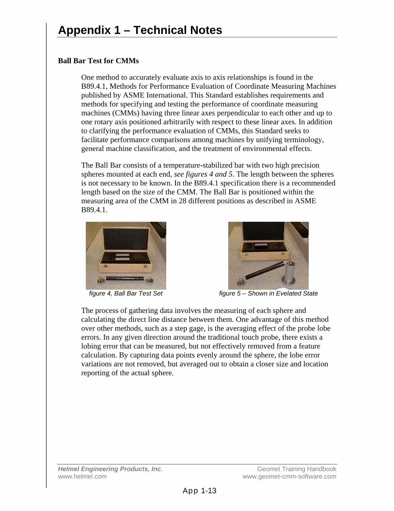
Appendix 1 – Technical Notes
Helmel Engineering Products, Inc. Geomet Training Handbookwww.helmel.com www.geomet-cmm-software.com
App 1-13
Ball Bar Test for CMMs
One method to accurately evaluate axis to axis relationships is found in theB89.4.1, Methods for Performance Evaluation of Coordinate Measuring Machinespublished by ASME International. This Standard establishes requirements andmethods for specifying and testing the performance of coordinate measuringmachines (CMMs) having three linear axes perpendicular to each other and up toone rotary axis positioned arbitrarily with respect to these linear axes. In additionto clarifying the performance evaluation of CMMs, this Standard seeks tofacilitate performance comparisons among machines by unifying terminology,general machine classification, and the treatment of environmental effects.
The Ball Bar consists of a temperature-stabilized bar with two high precisionspheres mounted at each end, see figures 4 and 5. The length between the spheresis not necessary to be known. In the B89.4.1 specification there is a recommendedlength based on the size of the CMM. The Ball Bar is positioned within themeasuring area of the CMM in 28 different positions as described in ASMEB89.4.1.
figure 4, Ball Bar Test Set figure 5 – Shown in Evelated State
The process of gathering data involves the measuring of each sphere andcalculating the direct line distance between them. One advantage of this methodover other methods, such as a step gage, is the averaging effect of the probe lobeerrors. In any given direction around the traditional touch probe, there exists alobing error that can be measured, but not effectively removed from a featurecalculation. By capturing data points evenly around the sphere, the lobe errorvariations are not removed, but averaged out to obtain a closer size and locationreporting of the actual sphere.

Appendix 1 – Technical Notes
Helmel Engineering Products, Inc. Geomet Training Handbookwww.helmel.com www.geomet-cmm-software.com
App 1-14
Once all 28 positions have been calculated, they can be entered in an Excelspreadsheet. The average of all 28 positions is first obtained and a companioncolumn of actual - average is calculated. These values are then plotted, as shownin figure 6.
figure 6, Ball Bar Results
The Maximum and Minimum values are found from the deviation column. Thespread between these values is considered the working tolerance. This value isoften reported as the volumetric accuracy of a CMM. It should be noted that thelength of the ball bar is often a small fraction of the actual measuring area.Therefore, the reported working tolerance only reflects the area the cubic size ofone ball bar length in the X, Y, and Z and should not be used to define the entireCMM.
figure 7, X / Y Squareness Deviation
In figure 7, we can visualize how to interpret the Ball Bar tests. We can see thedirect effect of a squareness deviation of the X versus Y-axis. The measureddistance of the lengths, d1 and d2, should be equal when the CMM has beenproperly setup. As the illustration shows, d1 being greater than d2 whichdemonstrates that the relationship between the X and Y-axis are not

Appendix 1 – Technical Notes
Helmel Engineering Products, Inc. Geomet Training Handbookwww.helmel.com www.geomet-cmm-software.com
App 1-15
perpendicular. When properly interpreted by a trained calibration engineer, all 28positions will effectively provide a picture of the intrinsic characteristics of yourCMM.
Many CMM manufacturers have abandoned building intrinsic accuracy in favorof 3D software compensation. This allows building of a CMM with little attentionto the accuracy of the assembly. The accuracy is acomplished by mapping theCMM with a known standard, such as a laser, then providing 3D compensationalgorithms to correct the inherent errors. However using only a laser does notremove all the inherent inaccuracies within the entire measuring cube.
There is no correct answer as to which method delivers a more accurate CMM. Inboth cases, the ability to perform field calibrations often becomes an economiccost the user must absorb. To perform a field calibration by mapping the CMMwith a laser system is a higher cost than adjusting for intrinsic accuracy.
Probe System Errors
Every probe system introduces inaccuracies toyour data point gathering. These include capturespeed, lobe errors, stylus lengths and probecontact pressure. Understanding the errors withinthe probe system can be very difficult. Mostelectronic touch probes have no index positionwhen installed on a CMM and can rotate to a newlocation moving the lobe error. Additionally,electronic touch probes are a simple switch andcan not determine the approach vector at the pointof contact. This simple fact makes it very difficultto map out probe errors. figure 8, Lobe Error Example

Appendix 1 – Technical Notes
Helmel Engineering Products, Inc. Geomet Training Handbookwww.helmel.com www.geomet-cmm-software.com
App 1-16
Lobe errors are mechanical limitations to the probe head. Lobes can have an errorin excess of .0001” deviation when capturing a point moving at 0° compared tocapturing a point at 60°. As shown in figure 8, the lobe error pattern istriangulated based on the mechanical layout of the kinematics probe alignment,see figure 9. The touch probe can be described as having low and high forcedirections when capturing a trigger, see figures 10 and 11.
figure 9, Force Direction figure 10, High Force Direction figure 11, Low Force Direction
Stylus lengths will add additional error to your system. A short length of about10mm will not influence your data points, however a 100mm length will increasethe error 10 fold to the lobe deviation. If you need to extend your stylus, werecommend the Renishaw PEL family of extensions. These are extensions thatmount between the probe head and probe body.
When the Trigger Force pressure is set too high, the probe error will increaseexponentially! Most mechanical probes allow you to adjust the tension applied tothe trigger mechanism, see manufacturers technical manual. Some touch probemodels, such as the Renishaw TP20, offer interchangeable modules with a presettrigger force. By increasing the pressure, you force the probe to trigger at a higherpressure that introduces stress and deflections in the stylus tip and extension.
Strain-gauge or piezo designed probes, such as the Renishaw TP200, minimizesthe lobe error by eliminating the mechanical kinematics design. However, thesegauges are susceptible to speed changes and the actual contact speed should bestable and consistent. Probes that use this technology should not be considered formanual CMMs.

Appendix 1 – Technical Notes
Helmel Engineering Products, Inc. Geomet Training Handbookwww.helmel.com www.geomet-cmm-software.com
App 1-17
Operator Influences
Finally the operator will provide the greatest error. If the operator captures datapoints with an inconsistent speed, repeatability errors are introduced. To test forspeed difference, lock the Z and X-axes on your CMM. Place a part on yourCMM and measure a +Y point. Increase the speed at which your capture points.At a certain speed you will begin to see variances in the reported results.
Other operator related issues include where you hold the CMM. If you have alarge CMM, probing while holding the probe bar just above the probe will actdifferently that when you are holding as far up the probe bar as possible. Theprobe bar is a lever, and by moving that lever you are placing strain on thesuperstructure of the CMM. If you gather data points before the CMM has‘settled’ you will get unreliable data points.
Data Point Spread
When measuring multi-point features, how you spread the data points will be thesingle greatest influence on the accuracy and repeatability of the feature. Forexample, if you capture data points on a circle using only a 15° sweep, the resultsare unreliable and not repeatable. If those same points were captured over a 300°sweep, the results would be accurate, see figure 12. The same holds true forPlanes spheres, cylinders and cones. Cylinders and cones require a proper spreadover the length otherwise the axis of the feature will not be reliable.
Arc(Degrees) Center Error Radius Error180 0.00014 0.00000120 0.00028 0.0001490 0.00048 0.0003460 0.00104 0.0009030 0.00409 0.0039520 0.00914 0.0089910 0.03549 0.035355 0.12823 0.12810
figure 12, Circle Errors
Imagine capturing two points on a line only .25” apart with a probing error of.0001”. The resulting line would have a repeatability error of .040” over 5.000” or0.4584 degree! If that line were used as part of the Part Coordinate System, thenall subsequent features would have questionable accuracy.