a d ln - defense technical information centerdtic.mil/dtic/tr/fulltext/u2/a154342.pdf · a d ln...
TRANSCRIPT

A D
Ln
0ITI
October 16 JU 38
yiproved fcr '~ "~;distribution unlimited.
LzJ
'ml..,UniTed States ArmyBelvoir, Research & Development. Center
FDor& Bel Z8r Virina 20-

Dawroy this report 44en it is no longer neddDo not return it to Ohn originator.
The citatin in this report of tide nams ofcommrcialy available products does not cotatitmt
official ndoqusmrent or approval of the use of such
products.
UNCLASSIFIFED" - SECURITt C'..ASS! -iCATION OF THIS PAGE (When Daoa Enfao.0
SENREAD INSTRUCTIONSSREPCRT DOCUMENTATION PAGEI EFORE COMPLETUNG FORM
I*. REPORT NUMBER N W~PIENT-5 CATALOG NUMBER
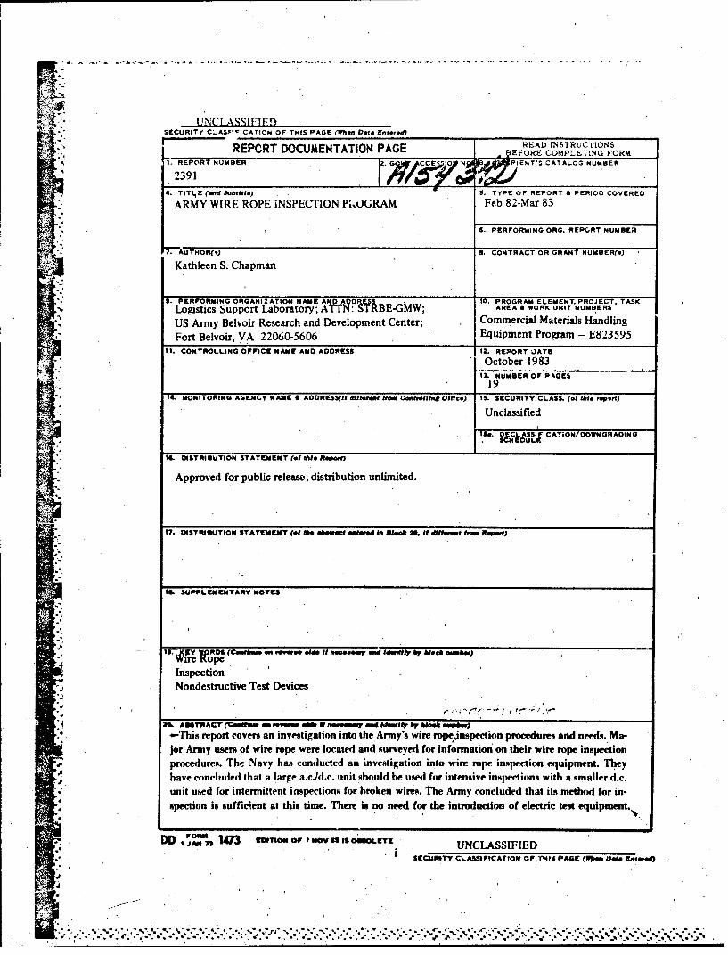
2391&4. TITLE (end Subtitle) 5. TYPE OF REPORT A PERIOD COVERED
ARMY WIRE ROPE INSPECTION P1,OGRAM Feb 82-Mar 83
6. PERFORMING ORG. REPORT NUMBER
"; "7. AUTHOR(,) S. CONTRACT OR GRANT NUMBER(@)
Kathleen S. Chapman
3. PERFORMING ORGANIZATION NAME A 00 10. PROGRAM ELEMENT. PROJECT. TASKLogistics Support Laboratory; 1N: :M•BE-GMW; AREA & WORK UNIT NUMBERS
US Army Belvoir Research and Development Center; Commercial Materials Handling
"Fort Belvoir, VA 22060-5606 Equipment Program - E82359511. CONTROLLING OFFICE NAME AND ADDRESS 12. REPORT OATE
October 198313. NUMBER OF PAGES
19"14. MONITORING AGENCY NAME B AODRESS(f•tdiffefaow Om CatrmfittnOlffce) IS. SECURITY CLASS. (of tibi f•ort)
Unclassified
ISO. DECLASSIFICATION/DOWNGRADINGSCHEDULE
IS. OISTRI6UTION STATEMENT (of tole Ropeat)
"Approved for public release; distribution unlimited.
"" 17. OISTRIilUTION STATEMENT (of Me 06.04 at enftred in Bleok *, It dfifeont ftr Ropme)
IIL SUPPLIEENVTARY NOTES
IV. . Y 'd •1
S (CeWýkam en remneo oade It" Seeamy end , IdmJlt by blo•eJh -ýk.)
InspectionNondestructive Test Devices
* AM AUr"ACr (0=w -w o N ,aw It by W r).. -This report covers an investigation into the. Army's wire rope/inspection procedures and needs. Ma-
jor Army users of wire rope were located and surveyed for information on their wire rope inspectionp•r ures. The Navy has conducted ain investigation into wire rope inspection equipment. Theyhave concluded that a large a.cJd.e. unit should be used for intensive inspections with a smaller d.c.unit used for intermittent inspections for broken wires. The Army concluded that its method for in-spection is sufficient at this time. There is no need for the introduction of electric test equipment.,.
"DIDO I F 54[3 EMITION OF I NOV6i ILETf UNCLASSIFIEDSECURITY CLASSIFICATIO1 OF TMIS PAGE (Iw.m Dae Entered)
%I .
". . -"""4 . . """""% . . . ,"," ,'• , . % . , . . "." -" . ."." " ,.". .•.--- •' °,- ''' -d '-' -. " . *
CONTENTS
Section Title Page
TABLES iv
I INTRODUCTION
1. Introduction 12. Background I3 . Scope 1
Hi DISCUSSION
4. Investigation 2
I . 5. Selection of Major Army Users of Wire Rope 26. Preparation of User Survey and User Performance 27. Survey Findings 2
III CONCLUSIONS
8. Conclusions 4
APPENDICES
A. LETTER REPORT-SURVEY OFNAVY WIRE ROPE 6
: .INSPECTION PROGRAMB. WIRE ROPE INSPECTION SURVEY
*io For
_ IS . .A. it LECT utietLnounced'-o
.. U , .+ 1.ificati.
JU BBy-
AvftiliatbiIlitT Cod avaland/or
1 Dtst special.
Q3N\
TABLES
Table Title Page
1Amounts- and Typical Diameters of Wire Rope Ordered 2
2 Wire Rope Inspection Survey Questionnaire 3
'IV
ARMY WIRE ROPE INSPECTION
1" 1. INTRODUCTION
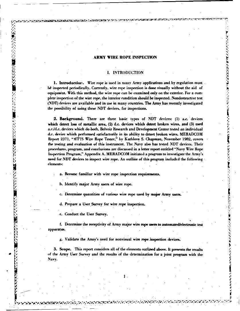
1. Introductiov. Wire rope is used in many Army applications and by regulation mustI. !h inspected periodically. Currently, wire rope inspection is done visually without the aid of
equipment. With this method, the wire rope can be examined only on the exterior. For a com-plete inspection of the wire rope, the interior condition should be inspected. Nondestructive test"(NDT) devices are available and in use in many cOuntries. The Army has recently investigatedthe possibility of using these NDT devices, for inspections.
- 2. Background. There are three basic types of NDT devices: (1) a.c. 'devices
which detect loss of metallic area, (2) d.c. devices which detect broken wires, and (3) useda.c.ld.c. devices which do both. Belvoir Research and Development Center tested an individuald.c. device which performed satisfactorily in its ability to detect broken wires. MERADCOMReport 2371, "MT75 Wire Rope Tester," by Kathleen S. Chapman., November 1982, coversthe testing and evaluation of this instrument. The, Navy also has tested NDT devices. Theirpiwedures, program, and conclusions are discussed in a letter report entitled "Navy Wire RopeInspection Program," Appendix A. MERADCOM initiated a program to investigate the Army's
* need for NDT devices to inspect wire rope. An outline of this program included the followingelements:
* • a. Become familiar with wire rope inspection requirements.
V b. Identify major Army users of wire rope.
c. Determine. quantities of various wire rope used by major Army users.
d. Prepare a User Survey for wire rope inspection. ,
"e. Conduct the User Survey.
f. Determine the receptivity of Army major wire rope users to automatedielectronie test .2
"apparatus.
g. Validate the Army's need for nonvisual wire rope.inspection devices. '
3. Scope. This report considers all of the elements outlined above. It presents the resultsof the Army User Survey and the results of the determination for a joint program with the,Navy.
S1, ,?
'p .-.-- *,-,L*g y•• • •"•"-• •. ; .',.',€•• • • "• "€ .' '. •-...e.. .%, .. -• . .•,• .•. ..-.-.-.. .

II. DISCUSSION
4. Investigation. The Army inspects their wire rope in accordance with the Departmentof the Army's Technical Bulletin TB 43-0142, which is equivalent to "he Office of Safety andHealth Administration (OSHA) requirements. This Technical Bulletin was acquired andreviewed.
5. Selection of Major Army Users of Wire Rope. AA Inveatory. ManagementSpecialist at the Defense Industrial Supply Center in Philadelph~a, Pennsylvania, was con-tacted for information on major Army users of wire rope. A minimum uti•;tation of 6,000. feetper two years was set as the criteria for an installation to be classified cs a major Army user ofwire rope. Within this criterion, four installations were cited as major Army users: FortBenning, Georgia; Fart Carson, Colorado; Tooele Army Depot, Utah; and Fort Bragg, NorthCarolina. Table I shows amounts and typical diameters of wire rope ordered at each installa-tion in a 2-year period. It should be noted that these installations use wire rope of greater andlesser diameters in addition to the sizes listed. For the purposes of this survey, only one sizediameter wire rope of 6,000 feet or more was needed to determine a major Army user of wire.rope.
Table 1. Amounts and Typical Diameters of Wire Rope Ordered
Ft. Benning Ft. Carson Tooele Army Depot Ft. Bragg
9,000 ft of 315,000 ft 6,000 ft of 18,000 ft of r518-in. of 3/8-in. 5/8-in: diameter 3/8-in.
diameter diameter diameter
6. Preparation of User Survey and User Performance. In order to assureun'formitv of the information obtr ined, a Wire Rope Inspection Survey Questionnaire was
"developed (Appendix B). Each installation was surveyed by telephone. The personnel who sup-plied the information included a Deputy Maintenance Manager located at Fort Benning, aField Maintcnancc Technician at Fort Carson, a Millrights Supervisor at Tooele Army Depot,
* and a Construction and General Inspection Foreman at Fort Bragg. All installations surveyedwere cooperative and supplied most of the information needed.
s.
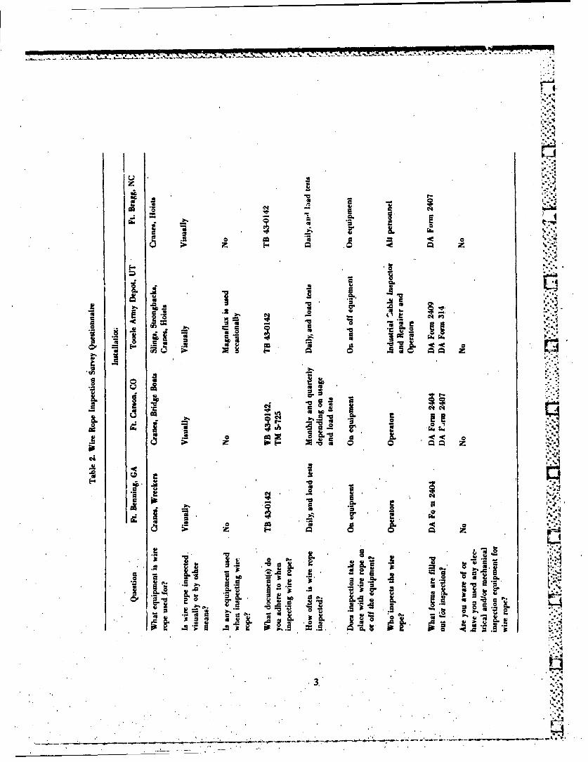
7. Surve-) Foindings.
the a. rable 2 was prepared from the data gathered from the four installations. In general,the installations were found to be consistent in their answers to the survey.
,2,
*. *. 2
.? *. *', ~ ¶~ .w v. ,- . .; .-- --. , .-' ;
C14-
cu1
- .0- a
LU vC4a
aLa
v IL
b. All four installations use a visual method to inspect their wire rope.
c. Wire rope is used on a variety of equipment such as cranes, hoists, strongbacks,bridge boals, and wreckers. Wire rope is also used for slings.
* -
d. No electrical and/or mechanical instruments are used for inspection of wire ropes. -'I
Tooele Army Depot occasionally uses magnaflux.
e. All installations surveyed adhere to Technical Bulletin TB 43-0142, "Safety Inspec-tion and Testing of Lifting Devices." Th.s document specifies that wire rope is to be'inspectedvisually daily. When wire rope is associated with an end item, it is to be inspected at the'sameinterval as the end item. Special attent;on should be given to end atqachments on the wire rope.
f. Daily insraon is porformed by the operators of the end item. Tooele Army Depotuses an industrial Cable h-spector tnd Repairer to inspect wire rope used at their instai!ation.Load test;-,, is p•.rfrmed prior to initi'.l use and on ail new, extensively repaired, or alteredlifting devices.
g. Inspection usually takes place with the wire rope on the end item. Tooele ArmyDepot occasionally inspects iv wire rope off the end item.
h. There are no specific inspection/maintenance forms to be completed for the wirerope when it is a component of the end item. If it is an end item in itself, an inspection/maintenance form is completed. LA
i. All installation! surveyed had never used electrieal or mechanical inspectiondevices for wire ropes, nor were they aware of any such devices.
TIIL CONCLUSIONS
8. Conclusions. It is concluded that:
a. The nondestructive wire rope inspection devices that are available provide more in-formation about the condition of the wire rope than do the visual inspection methods.
b. Although the installations contacted were not aware of nondestructive wire rope in-spection devices, they were receptive to the use of these devices.
c. Information acquired from the Defense Industrial Supply Center revealed that the,Navy uses three to four times more wire rope thain does the Army. The Navy mainly usesgreater amounts of the larger diameter wire rope.
4. • • T"
d. It is more appropriate to replace small diameter, short length wire rope than it is topurchase nondestructive wire rope inspection devices for Army use.
e. The Armyv's mi-thod of insfp--fiun of wire rope !ssufficient for meeting its needs atthi~s time. Therefoie, a joint prograir At the Navy 6A not planned.-
' .NJ
ta%

9
APPENDIX A
* -.. ..
LETTER REPORT
SURVEY OF NAVY WIRE ROPEINSPECTION PROGRAM 0
by
"Kathleen S. ChapmanMechanical Equipment Engineering Division
Logistics Support Ldxsra:ery
May 1983 -.
I. INTRODUCTION
1. Introduction. Wire rope inspection is a problem within the Navy as well as withinthe Army. Currently the Navy it using a method which does not lend itself to the inspection ofthe interior of wire rope- They use a technique which consists of holding a rag by hand,around the moving wire rope. 'If the rag is snagged, they search that area for a breken wire. Avisual inspection is also performed at this time. Caliper measarements on the exteriordiameters are taken to determine wear. Load testin- is performed yearly. The Army currentlyuses a visual inspection method. The Army's an.1 Navy', current procedures for detecting ,.-.defects within wire rope-are dangerous and sometimes inaccurate.
2. Background. An inspector for the Navy was fatally injured while inspecting wirerope on a large crane. This prompted the Navy to "r•tiate a. program to investigate the .'.
technology and capabilities of mephaiuical and electrouic wire rope inspection devices. TheNaval Facilities Engineering Cemmand (NAFAC), found that three types of inspection equip-ment exist. Individual a.c. and d.c. units and unitized a.e=i.e. units. The alternating currentunits detect loss of metallic area (LMA). Direct current units detect broken wires or local faults(LF).' Unitized a.cJd.c. units perform both jobs. The Naval Civil Engineering Laboratory' ...
(NCEL) in Port Hueneme. CA, wai tasked to conduct testi on these non-destructive inspectiondevices. Usually either a.c. or d.c. equipment is used, seldom both. The NCEL acquired a d.c.unit from Magnetic 'Analysis Corporation, NY, a unitized a.eJd.c. unit called a Magnographfrom Noranda Research Center, Quebec, Canada, and an individual a.c. unit was acquired-(-ource unkown).
3.. Purpose. The purpose of this report ih to present the findings of the investigation into*the Navy's Wire Rope Inspection Program.."
6'
6 " '

11. DISCUS'SION
a. The d.c. L-aii. i.c. unit, and the unitize~d a.cJd.c. unit were tested ,'idr hw 'aidr ;nlabioratorv and fi.-M' tests. In laboratory tests. theste unit,% were, temled on sample%. of wire ropewith man-made dlefects such as broken wires, corrosion. etc. In rield tests they were tused to in-s"ec a Manitowac Crarre. series 4100. having a lift capacity of .300 tons. The Magnograplhunit was also te-ted on a floating cran-e, YD17l1. having a lift capacity of(350 tons. Naval Civil*C_Engineering Laboratory, Trechnical Note N-1 594. "Nondestructive Tedi Equipment for WireRope." by H. H. Haynes and L D. Underhakke, October 1980. covens initial testing.
b. The Magnograph went through further testing to ileterniine. t~e operational limits ofthe equipment. Naval Civil Engineering Laboratory, Technical Note N-1659, "Test and0Evaluation of the Magnograph TMI Unit-A Nondestructive Wire, Rope Tester, "byý i DUnderhakke and H. H. Haynes. July 1982. covers this additional testing. During testing theNaval Civil Engineering Lahcvaoory concluded'that a remote data recorder which could ridepiggy-back on the sensor head was needed so that the inspectors would be able to obtain. datairons areas that are inaccessible or hazardous. Normally, the coponents of the, Magngahrare all 2tationary. The m.mote dlat recorder makes it po", ible for the unit~to he pulled along'awire rope. such as large tower guy wires. The remote data recorder was developed by Noranjaa
-lsearch Center. Naval Ci'.il Engineering Laboratory, Technical Note N-1657, 'Mhe RemoteData Recorderr An Onhoard Recorder for the Magnograph TM Nondestructive Test Wire RopeSensor Head." by L D. Underbakke., February 1983. covers true testing of this device.
c. The Navy inspectors needed a lightweight d.c. device for interim or preliminary in-spections when'broken wires were suspected. NCEL conducted a survey to find such. a unit.Out of the products evaluated. th,ý MT75 from NDTTechnologies, Inc. South Windsor. Con-necticut. 'vYap the smallest and easiest to use for local fault detection. The MT75 was tested inthe laboratory on a wire rope with man-made faults. It WAS also tested in the field on a oline of a 35-ton truck crane. The teAs'ing of this device is covered by Naval Civil EngineeringLaboratory Technical Report N-16 61, "Test and Evaluation of the MT75 Rope Tester-AHandheld NDT Wire Rope Inspection Device." by L D. Underbakke, March 1983..
5. Discunion of Findings.
a. A total of 5 pieces of equipment are needed when individual a~c. and dxc. inspectionunit are used. The Magncgraph used 3 pieces of equipment.
b. When a d.c. unit is used, the wire rope must be demagnetized before an axc. unit canbe used. This is a time conau~ning L. -d har '!Jous procedure.
c. The d.c. unit operated At speeds ~.50 to 500 ft/miin. Extremtely slow speeds armne-dcii to locate broken wires for detailed visual inspection.
d. The Magnograph can pinpoint a local faul within 2 in. The d.c. unit locates localfaults within 3 to 5 yd.
e. The Remote Data Recorder used with the Magnograph duplicates the performance•. of the Magnograph recording component. The data is recorded on a cassette which is removed
"and played back on the brush recorder component of the Magnograph.
f. The Remote Data Recorder has a remote time start-up circuit, which permits theinspector to leave a hazardous area before starting the recorder. It also has an auto start, which"can be set from I min to 12 h 59 min.
g. The MT75 has a speed compensation circuit which amplifies the signal, allowing
the wire rope to move as slow as 5 ft/min or as fast as 500 ftimin with no significant change in
•. the signal.
h. The MT75 is a lightweight handheld unit. At rope speeds in excess of 200 ft/min itbecomes difficult for the inspector to hold the unit. The inspector can be pulled along with the
MT75 if it mags a fault on the wire rope, or it could be pulled out of the inspector's hands. TheMT75 can be removed by pulling it perpendicular from the wire rope, which helps inelinjAuating this problem.
III. CONCLUSION
6. Conchoion. The Navy concluded that:
a. Both the exterior and interior of a wire rope must be inspected for local faults andless of metallic area for a complete inspection.
b. Ba - on their testing results, the Magnograph was found to be superior in ease ofSand' rerform 3 ce to the individual a.c. and d.c. units. They recommend that the Navy pro-
cu t- zed a.cid.c. equipment for meeting its needs in inspecting metallic wire rope.
c. The remote data recorder for the Magnograph should be used in hazardous areasam areas which deny inspectors access.
d. The MT75 is recommended by the Navy to-be used as an inspection instrument for.-sma diameter (3/8 and 3/4 in.) wirc ropes. It provides information that cannot be obtainedfro n the rag and visual inspection methods. It can also greatly reduce inspection time.
e. The Naval Facilities Engineering Command funding for the wire rope inspection,.•~ eq ipment program has been exhausted. The Office of Naval Research has been funded for
further research in the wire rope inspectiua area. Their program will be followed by the NavalFa ilities Engineering Command.
,,~~~~~~~~~~~~~~~~~...... .....-.•..-...... .-..-. .-.. •.-.-.-.-.-........-.-....*.*..--..-,-.- --- ,-...-.-..
___.-._____.-.______.-__________ .e - I-,-.-.' . -..--....-.. ... ..- ..... .... ..-. .... . . .'-.....-.-- ..- -'.-... ..... -.-..... .. .,. ...
f. Ten MT75 units are scheduled to be procured for by shipyards and other installa-tions for use in inspec~ions of wire rope. Two to three Magnograph units have also been pro-cured for use.
g. Further testing is needed using the Maginogaph and MT7S so that a glossary ofdefect signals can be published to assist inspectors in data interpretation.
9
............ P
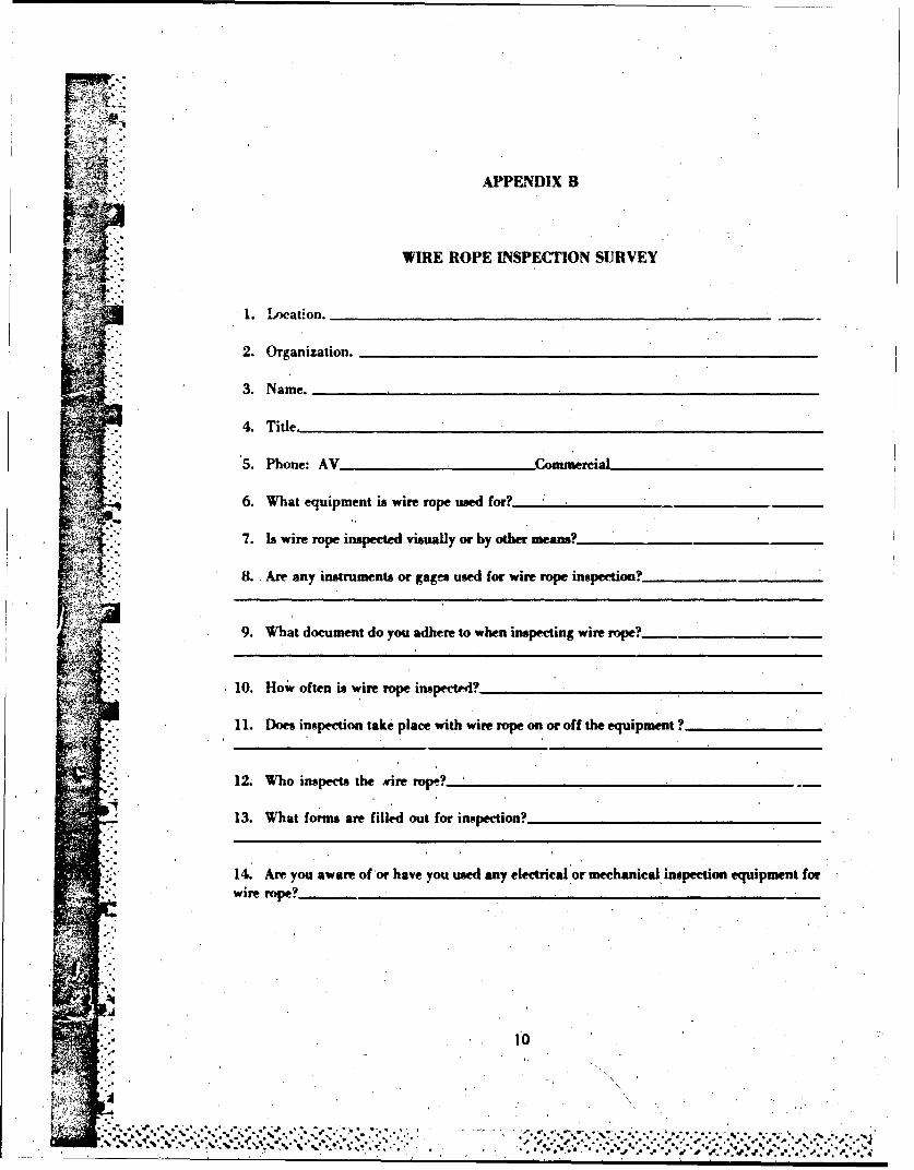
APPENDIX B
WIRE ROPE INSPECTION SURVEYV ~~~~~~1. Location.____________________ ______
2. Organization.
3. Name.______________________ ___
4. Title._____________________________________
5. Phone: AV Cmrercial
6. What equipment is wire rope used for?_________
7. Is wire rope inspected visually or by other Means?____________
B. Are any instruments or gages used for wire rope inspection?
9. What document do you adhere to when inspecting wire rope?....
10. How often is wire rope inspece"?
11. Does inspection take place with wire rope on or off the equipment?
12. Who inspects the mire rope.?
13. What forms are filled out for inspection?
14. Are you aware of'or have you used any electrical or mechanicial, inspection equipment forwire rope?
10
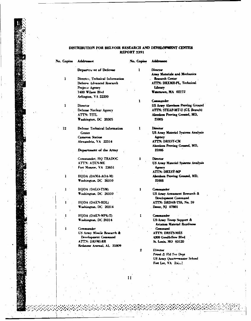
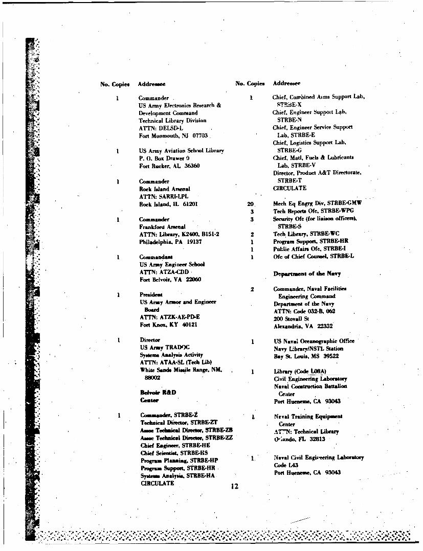
"DISTRIBUTION FOR BELVOIJ RESEARCH AND DEVEKOPMI1T CENTER"REPORT 2391
No. Copies Addressee No. Copie. Addrese
"Depfta.w.nt of Defense 1 DirectmAmy Materials and Mechanics
I Director, Technical Information Research CenterDefen-e Advanced Research ATMN: DRXMR-PL, TechniealPromje*z Agency LiMy"1400 Wilson Blvd Waertown, MA 02172Arlington, VA 22209
I CAmmanderI Director US Army Aberdeen Proving Ground
Defense Nuclear Agency ATTN: STEAP.MT-U (GE Branch)ATTN: TITL Aberdeen Proving Ground. MD,Washington, DC 20305 21005
12 Defense Technical Information I Director
"Center US Army Materiel Systems AnalysisCameron Station AgencyAlexandria, VA 22314 ATrN: DRXSY-CM
"Aberdeen Proving Ground. MD.Depam-ment of the Army 21005
Commander, HQ TRADOC DirectorATTN: ATEN-ME US Army Materiel Systems AnalysisFort Monroe. VA 23651 Agency
ATrN: DRXSY-MPI HQDA (DAMA-AOA-M) Aberdeen Proving Ground, MD,
Washington. DC 20310 21005
I HQDA (DALO-TSM) 1 CoAmanderWashington, DC 20310 US Amy Armament Research &
"Develpment CommandI IIQDA (DAEN-RDL) ATTN: DRDAR-TSS No. 59
Washington. DC 20314 Dow. NJ 07801
SHQDA (DAEN-MPE-T) I CommanderWashington. DC 20314 USArmy Troop Support &
Aviation Materiel ReadinessI Commander Command
US Army Missile Research & ATTN: DRSTs-MESDevelopment Command 4300 Goodfellow Blvd
AT'TN: DRSMI-RR St. Louis, MO 63120
Redstone Arsenal, AL 358092 l)itor
Petrol & Rld Svc DeptUS Army Quat- nsawr SchoolFort Lree VA 2.•G•I
II
i2!
,• • • •. ,- ,,. ',.'•.,\ 'L
No. Copies Addressee No. Copies Addressee
S1 Commander 1 Chief, Cowhined Aims Support Lab,US Army Electronics Research & .QTRiE-XDevelopment Command Chief, Engineer Suppoit Lab,Technical Library Division STRBE-NATTN: DELSD-L Chief, Engineer Service Support
Fort Monmouth, NJ 07703, Lab, STRBE-E, Chief, Logistics Support Lab,
US Army Aviation School Library STRBE-GP. 0. Box Drawer 0 Chief, Mad, Fuels & Lubricants
Fort Rucker, AL 36360 Lab, STRBE-VDirector, Product A&T Directorate,
Commander STRBE-T
Rock Island Arsenal CIRCULATEATTN: SARRI-LPLRock sland, IL 61201 20 Mech Eq Engrg Div. STRBE-GMW
1a3 Tech Reports Ofe, STRBE-WPG
SCommander 3 Security Oe (for liaison officers),SFrankfod Arsenial STRBE-S
ATTN: Library, K2400. B151-2 2 Tech Library, STRBE-WCPhiladelphia, PA 19137 1 Program Support, STRBE-HR
1 Public Affairs Ofr, STRBE-I1 Commandant 1 Ofe of Chief Counsel, STRBE-L
US Army Engineer SchoolATTN: ATZA-CDD Depawtment of the NavyFort Belvoir, VA 22060
2 Commander. Naval FacilitiesPresident Engineering Command
US Army Armor and Engineer Department of the Navy
Board ATTN: Code 032-B, 062
"-" ATTN: ATZK-AE-PD'E 200 Stovall St
Fort Knox, KY 40121 Alexandria, VA 22332
Director 1 US Naval Oceanographic Office
US Army TRADOC Navy 1-braryINSTL Station
Systems Analysis Activity Bay St. Louis, MS 39522
ATTN: ATAA-SL (Tech Lib)White Sands Missile Range. NM. Library (Code LOAA)
889M2 Civil Engineering Laboratory
Naval Construction BattalionBlvufr R&D Ceater
" est- Port Hueneme, CA 93043
Commander. STRBE-Z Naval Training EquipmentTechnical Director. STRBE-ZT Center
Amse Technieal Ditetor, 3TRBE-ZB ATN': Technical Library
Assoc Technical Diretor. STRBE-ZZ " 'gando, FL 32813
Chied Engineer, STRBE-HE
".." Chief Scientist, STRBE-HS
" Program Planning. STRBE-HP 1 Naval Civil Engiireering Laboratory
Program Support, STRBE-HR Cd 4Systems Analysis. STRBE-HA Port Hoeneue, CA 93043
CIRCULATE 12
e*
.... . O . . v r . -.
4 a
... *',•.*. ' v.7. ',',e .% -,.+ .. 7 .', ' 2,.,,q.€, ;, "•• •L:....'s.,' ?.,° €. ' -' ...a-. ..-. .' ' .' ,., ..... ,a. ',++.

No. Copies Addrewsee
Department of the Air Force
HQ USAFIRDPT,ATTN: Mr. Allan EaffyWashington, DC 20330
HQ USAF/LEEEUChief, Utilities BranchWaphington. DC 20330
1 ~i US Air.FomeHQ Air Force Engineering &
Service CenterTechnical Library FL 70.50Tyndall AFB, FL 32403
!.
13
\\..s-.-..~ t. t * : .. . .
%g
* 7
,i
C'
Cr
I
Io.
'C
S~*DTIC•