a design method for slurry trench wall stability in sandy ground based on the elasto-plastic fem
DESCRIPTION
Deep-trench excavation supported by slurry has become a widely used technique for theconstruction of diaphragm walls. It has been proved by numbers of ®eld tests, scale modeltests and numerical analyses that the supporting eect of the slurry in the trench will provide sucient stability for the deep-trench excavations. However, there is still neither a generally accepted theory of the failure mechanisms of the slurry trench, nor a widely used design method. This paper gives suggestions for the practical design on the stability of the slurry trench based on the elasto-plastic ®nite-element method (FEM) analysis, which consists of two parts. The ®rst part is concerned with the evaluation of slurry trench stability in terms of safety factor. The safety factor was calculated using the shear strength reduction technique in the FEM and veri®ed by comparison with centrifuge tests. The second part suggests a method for choosing the preliminary slurry parameters, i.e. the height of slurry ®lling and slurry density, based on the active earth pressure FEMTRANSCRIPT
A design method for slurry trench wallstability in sandy ground based on the
elasto-plastic FEM
Pavol Oblozinsky a, Keizo Ugai a,*, Masaaki Katagiri b,Kunio Saitoh b, Takeshi Ishii b, Toru Masuda c,
Kiyoshi Kuwabara c
aDepartment of Civil Engineering, Gunma University, JapanbNikken Sekkei Nakase Geotechnical Institute, Kawasaki, Japan
cEast Japan Railway Co.Ltd, Tokyo, Japan
Abstract
Deep-trench excavation supported by slurry has become a widely used technique for the
construction of diaphragm walls. It has been proved by numbers of ®eld tests, scale modeltests and numerical analyses that the supporting e�ect of the slurry in the trench will providesu�cient stability for the deep-trench excavations. However, there is still neither a generally
accepted theory of the failure mechanisms of the slurry trench, nor a widely used designmethod. This paper gives suggestions for the practical design on the stability of the slurrytrench based on the elasto-plastic ®nite-element method (FEM) analysis, which consists oftwo parts. The ®rst part is concerned with the evaluation of slurry trench stability in terms of
safety factor. The safety factor was calculated using the shear strength reduction technique inthe FEM and veri®ed by comparison with centrifuge tests. The second part suggests a methodfor choosing the preliminary slurry parameters, i.e. the height of slurry ®lling and slurry den-
sity, based on the active earth pressure FEM. # 2000 Published by Elsevier Science Ltd. Allrights reserved.
Keywords: Slurry trench; Shear strength reduction method; Stability
Computers and Geotechnics 28 (2001) 145±159
www.elsevier.com/locate/compgeo
0266-352X/01/$ - see front matter # 2000 Published by Elsevier Science Ltd. All rights reserved.
PI I : S0266-352X(00 )00028 -8
* Corresponding author. Tel.: +81-277-30-1620; fax: +81-277-30-1601.
E-mail address: [email protected] (K. Ugai).
1. Introduction
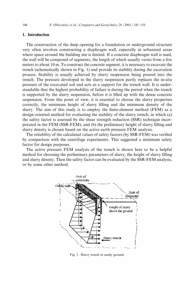
The construction of the deep opening for a foundation or underground structurevery often involves constructing a diaphragm wall, especially in urbanized areaswhere space around the building site is limited. If a concrete diaphragm wall is used,the wall will be composed of segments, the length of which usually varies from a fewmeters to about 10 m. To construct the concrete segment, it is necessary to excavate thetrench (schematically shown in Fig. 1) and provide its stability during the excavationprocess. Stability is usually achieved by slurry suspension being poured into thetrench. The pressure developed in the slurry suspension partly replaces the in-situpressure of the excavated soil and acts as a support for the trench wall. It is under-standable that the highest probability of failure is during the period when the trenchis supported by the slurry suspension, before it is ®lled up with the dense concretesuspension. From this point of view, it is essential to choose the slurry propertiescorrectly, the minimum height of slurry ®lling and the minimum density of theslurry. The aim of this study is to employ the ®nite-element method (FEM) as adesign-oriented method for evaluating the stability of the slurry trench, in which (a)the safety factor is assessed by the shear strength reduction (SSR) technique incor-porated in the FEM (SSR-FEM), and (b) the preliminary height of slurry ®lling andslurry density is chosen based on the active earth pressure FEM analysis.The reliability of the calculated values of safety factors (by SSR-FEM) was veri®ed
by comparison with the centrifuge experiments. This suggested a minimum safetyfactor for design purposes.The active pressure FEM analysis of the trench is shown here to be a helpful
method for choosing the preliminary parameters of slurry, the height of slurry ®llingand slurry density. Then the safety factor can be evaluated by the SSR-FEM analysis,or by some other method.
Fig. 1. Slurry trench in sandy ground.
146 P. Oblozinsky et al. / Computers and Geotechnics 28 (2001) 145±159
2. FEM mesh and soil properties
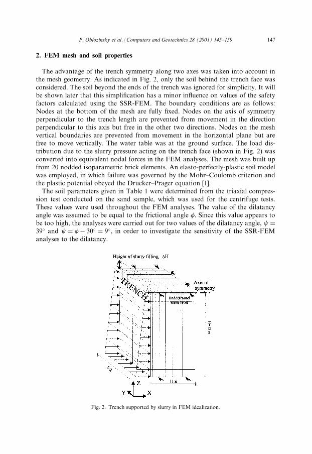
The advantage of the trench symmetry along two axes was taken into account inthe mesh geometry. As indicated in Fig. 2, only the soil behind the trench face wasconsidered. The soil beyond the ends of the trench was ignored for simplicity. It willbe shown later that this simpli®cation has a minor in¯uence on values of the safetyfactors calculated using the SSR-FEM. The boundary conditions are as follows:Nodes at the bottom of the mesh are fully ®xed. Nodes on the axis of symmetryperpendicular to the trench length are prevented from movement in the directionperpendicular to this axis but free in the other two directions. Nodes on the meshvertical boundaries are prevented from movement in the horizontal plane but arefree to move vertically. The water table was at the ground surface. The load dis-tribution due to the slurry pressure acting on the trench face (shown in Fig. 2) wasconverted into equivalent nodal forces in the FEM analyses. The mesh was built upfrom 20 nodded isoparametric brick elements. An elasto-perfectly-plastic soil modelwas employed, in which failure was governed by the Mohr±Coulomb criterion andthe plastic potential obeyed the Drucker±Prager equation [1].The soil parameters given in Table 1 were determined from the triaxial compres-
sion test conducted on the sand sample, which was used for the centrifuge tests.These values were used throughout the FEM analyses. The value of the dilatancyangle was assumed to be equal to the frictional angle �. Since this value appears tobe too high, the analyses were carried out for two values of the dilatancy angle, �39� and � �ÿ 30� � 9�, in order to investigate the sensitivity of the SSR-FEManalyses to the dilatancy.
Fig. 2. Trench supported by slurry in FEM idealization.
P. Oblozinsky et al. / Computers and Geotechnics 28 (2001) 145±159 147
3. Shear strength reduction technique
The shear strength reduction technique has developed remarkably over recentdecades and has come to be used for evaluating the safety factor, especially inmethods like the FEM and FDM. With the development of fast desktop computers,these methods have become widely available not only for research purposes but also forpractical design. The shear strength reduction technique was used to evaluate the safetyfactor of slopes as early as 1975 by Zienkiewicz [2], later applied by Naylor [3] andMatsui and San [4]. The validity of the shear strength reduction technique was dis-cussed and demonstrated by Ugai and Leshchinsky [5], who compared the stability of asimple 3D vertical cut analyzed by FEMand limited equilibriummethod. Dawson et al.[6] made a comparison between the SSR applied in the FDM and the LEM solutionfor the stability of a 2D embankment. In both cases similar results were reported.The essence of the SSR technique is the reduction of the soil strength parameters
until the soil fails. The soil strength parameters used in FEM procedures are de®nedas follows:
cF � c
F;�F � tanÿ1
tan�
F
� ��1�
in which F is a parameter which reduces the soil strengths and c and � are the soilstrength parameters.In the case of analyses on the slurry trench stability, the load due to the stabilising
pressure of the slurry was applied as a single increment in the ®rst step of the cal-culation in which the value of F was equal to 0.01. A small value of the parameter Fgives high values of the strength parameters and the domain will be in the elasticcondition. The parameter F is then incrementally increased by 0.01 and the soilstrength is correspondingly reduced. This is repeated until failure occurs. At thisinstant, the value of the parameter, F, comes to be the global minimal safety factor,FS, with the same meaning as the safety factor de®ned in LEM.The moment when global failure occurs is found with the help of the number of
the Newton±Raphson iterations. The convergence criterion is satis®ed if the dis-placement increment between two successive steps, Fi and Fi�1, divided by the totaldisplacement is less than 10ÿ5 within 1000 iterations. If this is not achieved, it isassumed that the solution diverges and the system has collapsed.
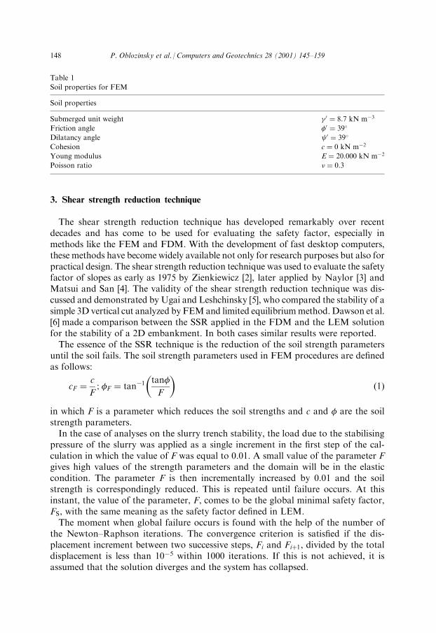
Table 1
Soil properties for FEM
Soil properties
Submerged unit weight 0 � 8:7 kN mÿ3
Friction angle �0 � 39�
Dilatancy angle 0 � 39�
Cohesion c � 0 kN mÿ2
Young modulus E � 20:000 kN mÿ2
Poisson ratio � � 0:3
148 P. Oblozinsky et al. / Computers and Geotechnics 28 (2001) 145±159
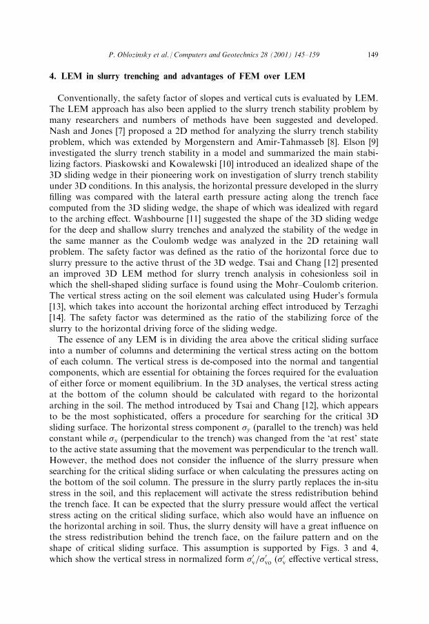
4. LEM in slurry trenching and advantages of FEM over LEM
Conventionally, the safety factor of slopes and vertical cuts is evaluated by LEM.The LEM approach has also been applied to the slurry trench stability problem bymany researchers and numbers of methods have been suggested and developed.Nash and Jones [7] proposed a 2D method for analyzing the slurry trench stabilityproblem, which was extended by Morgenstern and Amir-Tahmasseb [8]. Elson [9]investigated the slurry trench stability in a model and summarized the main stabi-lizing factors. Piaskowski and Kowalewski [10] introduced an idealized shape of the3D sliding wedge in their pioneering work on investigation of slurry trench stabilityunder 3D conditions. In this analysis, the horizontal pressure developed in the slurry®lling was compared with the lateral earth pressure acting along the trench facecomputed from the 3D sliding wedge, the shape of which was idealized with regardto the arching e�ect. Washbourne [11] suggested the shape of the 3D sliding wedgefor the deep and shallow slurry trenches and analyzed the stability of the wedge inthe same manner as the Coulomb wedge was analyzed in the 2D retaining wallproblem. The safety factor was de®ned as the ratio of the horizontal force due toslurry pressure to the active thrust of the 3D wedge. Tsai and Chang [12] presentedan improved 3D LEM method for slurry trench analysis in cohesionless soil inwhich the shell-shaped sliding surface is found using the Mohr±Coulomb criterion.The vertical stress acting on the soil element was calculated using Huder's formula[13], which takes into account the horizontal arching e�ect introduced by Terzaghi[14]. The safety factor was determined as the ratio of the stabilizing force of theslurry to the horizontal driving force of the sliding wedge.The essence of any LEM is in dividing the area above the critical sliding surface
into a number of columns and determining the vertical stress acting on the bottomof each column. The vertical stress is de-composed into the normal and tangentialcomponents, which are essential for obtaining the forces required for the evaluationof either force or moment equilibrium. In the 3D analyses, the vertical stress actingat the bottom of the column should be calculated with regard to the horizontalarching in the soil. The method introduced by Tsai and Chang [12], which appearsto be the most sophisticated, o�ers a procedure for searching for the critical 3Dsliding surface. The horizontal stress component �y (parallel to the trench) was heldconstant while �x (perpendicular to the trench) was changed from the `at rest' stateto the active state assuming that the movement was perpendicular to the trench wall.However, the method does not consider the in¯uence of the slurry pressure whensearching for the critical sliding surface or when calculating the pressures acting onthe bottom of the soil column. The pressure in the slurry partly replaces the in-situstress in the soil, and this replacement will activate the stress redistribution behindthe trench face. It can be expected that the slurry pressure would a�ect the verticalstress acting on the critical sliding surface, which also would have an in¯uence onthe horizontal arching in soil. Thus, the slurry density will have a great in¯uence onthe stress redistribution behind the trench face, on the failure pattern and on theshape of critical sliding surface. This assumption is supported by Figs. 3 and 4,which show the vertical stress in normalized form �0v=�
0vo (�0v e�ective vertical stress,
P. Oblozinsky et al. / Computers and Geotechnics 28 (2001) 145±159 149
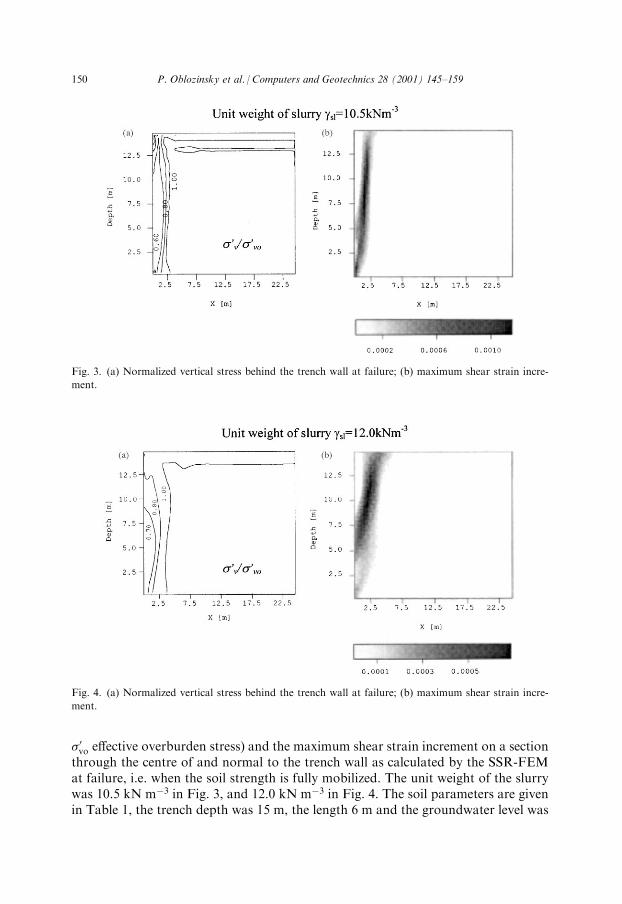
�0vo e�ective overburden stress) and the maximum shear strain increment on a sectionthrough the centre of and normal to the trench wall as calculated by the SSR-FEMat failure, i.e. when the soil strength is fully mobilized. The unit weight of the slurrywas 10.5 kN mÿ3 in Fig. 3, and 12.0 kN mÿ3 in Fig. 4. The soil parameters are givenin Table 1, the trench depth was 15 m, the length 6 m and the groundwater level was
Fig. 3. (a) Normalized vertical stress behind the trench wall at failure; (b) maximum shear strain incre-
ment.
Fig. 4. (a) Normalized vertical stress behind the trench wall at failure; (b) maximum shear strain incre-
ment.
150 P. Oblozinsky et al. / Computers and Geotechnics 28 (2001) 145±159
at the ground surface. As can be seen from Figs. 3a and 4a, which show the nor-malized vertical stress, �0v=�
0vo, the gradient of reduction of vertical stress is higher
when the slurry density is lower; this re¯ects the smaller supporting e�ect of theslurry pressure in Fig. 3a. The critical sliding wedge can be estimated from the pic-tures of maximum shear strain distribution obtained from the SSR-FEM solution,as shown in Figs. 3b and 4b. Comparison of Figs. 3 and 4 highlights that di�erentdensities of slurry (thus di�erent pressures acting on the trench wall) will cause dif-ferent failure patterns.The main advantage of the SSR-FEM is its ability to calculate the stress state in
the soil, taking into account both, the arching e�ect and the slurry pressure in thetrench, while in the LEM it is necessary to adopt complicated assumptions toaccount for the 3D e�ect. The advantages, which the 3D SSR-FEM o�ers over theLEM, should be taken into account in the assessment of the slurry trench stabilityand the prediction of safety factors in practical design.
5. Finite element analysis on centrifuge test
The slurry trench stability analyses were carried out using the mesh shown in Fig. 2to investigate the capability of the shear strength reduction technique in slurrytrench problems and to examine the reliability of the calculated safety factor.Results of analyses were veri®ed by comparison with the available results of thecentrifuge experiments reported by Katagiri et al [15,16]. The trench length in theFEM analysis varied from 1.5m to1(2D), the depth was 15 m and the groundwaterlevel was at the ground surface. The model soil was fully saturated and the analysiswas carried out in the terms of e�ective stress and drain condition was assumed. Thehorizontal e�ective stress due to the slurry pressure acting on the trench face, asindicated in Fig. 2 (unit weight of slurry s1 � 10:5 kN mÿ3), was replaced by theequivalent nodal forces. The soil parameters are given in Table 1.The aim of the centrifuge experiments on slurry trench stability [15,16] in fully
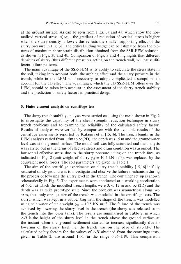
saturated sandy ground was to investigate and observe the failure mechanism duringthe process of lowering the slurry level in the trench. The container set up is shownschematically in Fig. 5. The experiments were conducted at a working accelerationof 60G, at which the modelled trench lengths were 3, 6, 12 m and 1 (2D) and thedepth was 15 m in prototype scale. Since the problem was symmetrical along twoaxes, thus only one quarter of the trench was modelled in the centrifuge tests. Theslurry, which was kept in a rubber bag with the shape of the trench, was modelledusing salt water of unit weight s1 � 10:5 kN mÿ3. The failure of the trench wasachieved by lowering the slurry level in the trench (the slurry was released fromthe trench into the lower tank). The results are summarised in Table 2, in which�H is the height of the slurry level in the trench above the ground surface atthe instant when the ground settlement started to increase signi®cantly due tolowering of the slurry level, i.e. the trench was on the edge of stability. Thecalculated safety factors for the values of �H obtained from the centrifuge tests,given in Table 2, are around 1.00, in the range 0.96±1.19. This comparison
P. Oblozinsky et al. / Computers and Geotechnics 28 (2001) 145±159 151
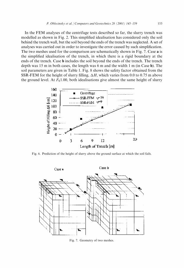
suggests that if FS � 1:2 had been chosen as the minimum value for the design,the trench wall would be stable.The comparison between the SSR-FEM and centrifuge experiments is shown in
Fig. 6. In this case the �H, which was obtained from the centrifuge tests, is com-pared with the prediction of the SSR-FEM analyses. It was assumed that the valueof the safety factor 1.00 indicates the limit of stability. The graphical comparison inFig. 6 shows that the relationship between the trench length and the minimumheight of the slurry ®lling from the FEM analyses is almost linear while the rela-tionship obtained from the centrifuge test is not linear. This is an interesting ®ndingsince from the nature of the 3D analyses it could be expected that the relationshipwould be non-linear.As was mentioned before, the angle of dilatancy � 39� (Table 1) appears to be
too high, therefore an additional set of calculations was carried out in which thedilatancy � �ÿ 30� � 9�. The results are also plotted in Fig. 6 by the dashed line.As can be seen, the smaller angle of dilatancy resulted in a slight increase of theheight of the slurry ®lling needed to prevent failure. The sensitivity of the SSR-FEMto dilatancy does not appear to be signi®cant in the Mohr±Coulomb soil model usedhere. The di�erence is less than 2%.
Table 2
Predicted safety factor
Trench length (m) �H (m) (from centrifuge experiment) FS (predicted by SSR-FEM)
3 0.18 1.03
6 0.54 1.19
12 0.92 1.18
2D 1.03 0.96
Fig. 5. Model of slurry trench in centrifuge container.
152 P. Oblozinsky et al. / Computers and Geotechnics 28 (2001) 145±159
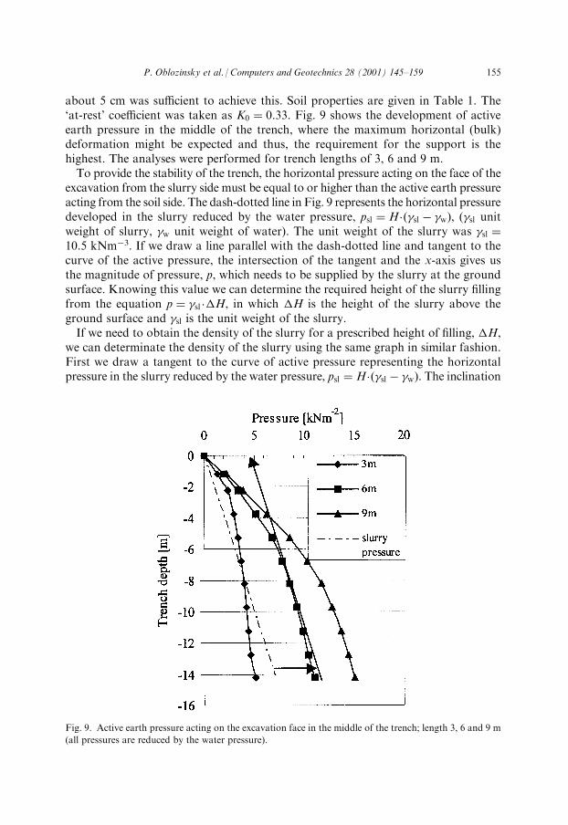
In the FEM analyses of the centrifuge tests described so far, the slurry trench wasmodelled as shown in Fig. 2. This simpli®ed idealisation has considered only the soilbehind the trench wall, but the soil beyond the ends of the trench was neglected. A set ofanalyses was carried out in order to investigate the error caused by such simpli®cation.The two meshes used for the comparison are schematically shown in Fig. 7. Case a isthe simpli®ed idealisation of the trench, in which there is a rigid boundary at theends of the trench. Case b includes the soil beyond the ends of the trench. The trenchdepth was 15 m in both cases, the length was 6 m and the width 1 m (in Case b). Thesoil parameters are given in Table 1. Fig. 8 shows the safety factor obtained from theSSR-FEM for the height of slurry ®lling, �H, which varies from 0.0 to 0.75 m abovethe ground level. At FS1:00, both idealisations give almost the same height of slurry
Fig. 6. Prediction of the height of slurry above the ground surface at which the soil fails.
Fig. 7. Geometry of two meshes.
P. Oblozinsky et al. / Computers and Geotechnics 28 (2001) 145±159 153
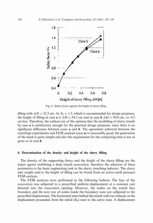
®lling with �H � 32:5 cm. At FS � 1:2, which is recommended for design purposes,the height of ®lling in case a is �H � 54:2 cm and in case b �H � 50:0 cm, i.e. 4.2cm less. Therefore, the authors are of the opinion that the modelling of slurry trenchby case a is satisfactory enough for the practical design purposes, since there is nosigni®cant di�erence between cases a and b. The agreement achieved between thecentrifuge experiments and FEM analysis (case a) is reasonably good, the generationof the mesh is quite simple and also the requirement for the computing time is not asgreat as in case b.
6. Determination of the density and height of the slurry ®lling
The density of the supporting slurry and the height of the slurry ®lling are themajor agents stabilising a deep trench excavation, therefore the selection of theseparameters is the basic engineering task in the slurry trenching industry. The slurryunit weight and/or the height of ®lling can be found from an active earth pressureFEM analysis.The FEM analyses were performed in the following fashion: The face of the
excavation was subjected to a prescribed uniform displacement at a constant ratedirected into the excavation opening. However, the nodes on the trench faceboundary and the next row of nodes inside the boundary were not subjected to theprescribed displacement. The horizontal stress behind the trench wall was reduced, as thedisplacement proceeded, from the initial (K0) state to the active state. A displacement
Fig. 8. Safety factor against the height of slurry ®ling.
154 P. Oblozinsky et al. / Computers and Geotechnics 28 (2001) 145±159
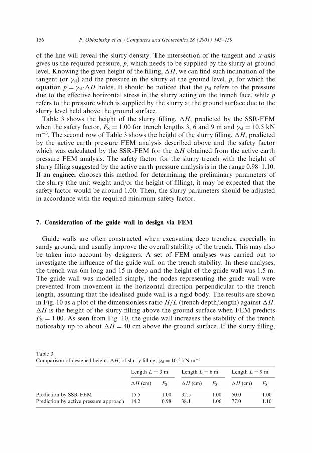
about 5 cm was su�cient to achieve this. Soil properties are given in Table 1. The`at-rest' coe�cient was taken as K0 � 0:33. Fig. 9 shows the development of activeearth pressure in the middle of the trench, where the maximum horizontal (bulk)deformation might be expected and thus, the requirement for the support is thehighest. The analyses were performed for trench lengths of 3, 6 and 9 m.To provide the stability of the trench, the horizontal pressure acting on the face of the
excavation from the slurry side must be equal to or higher than the active earth pressureacting from the soil side. The dash-dotted line in Fig. 9 represents the horizontal pressuredeveloped in the slurry reduced by the water pressure, psl � H� sl ÿ w� �, ( sl unitweight of slurry, w unit weight of water). The unit weight of the slurry was sl �10:5 kNmÿ3. If we draw a line parallel with the dash-dotted line and tangent to thecurve of the active pressure, the intersection of the tangent and the x-axis gives usthe magnitude of pressure, p, which needs to be supplied by the slurry at the groundsurface. Knowing this value we can determine the required height of the slurry ®llingfrom the equation p � sl ��H, in which �H is the height of the slurry above theground surface and sl is the unit weight of the slurry.If we need to obtain the density of the slurry for a prescribed height of ®lling, �H,
we can determinate the density of the slurry using the same graph in similar fashion.First we draw a tangent to the curve of active pressure representing the horizontalpressure in the slurry reduced by the water pressure, psl � H� sl ÿ w� �. The inclination
Fig. 9. Active earth pressure acting on the excavation face in the middle of the trench; length 3, 6 and 9 m
(all pressures are reduced by the water pressure).
P. Oblozinsky et al. / Computers and Geotechnics 28 (2001) 145±159 155
of the line will reveal the slurry density. The intersection of the tangent and x-axisgives us the required pressure, p, which needs to be supplied by the slurry at groundlevel. Knowing the given height of the ®lling, �H, we can ®nd such inclination of thetangent (or sl) and the pressure in the slurry at the ground level, p, for which theequation p � sl ��H holds. It should be noticed that the psl refers to the pressuredue to the e�ective horizontal stress in the slurry acting on the trench face, while prefers to the pressure which is supplied by the slurry at the ground surface due to theslurry level held above the ground surface.Table 3 shows the height of the slurry ®lling, �H, predicted by the SSR-FEM
when the safety factor, FS � 1:00 for trench lengths 3, 6 and 9 m and sl � 10:5 kNmÿ3. The second row of Table 3 shows the height of the slurry ®lling, �H, predictedby the active earth pressure FEM analysis described above and the safety factorwhich was calculated by the SSR-FEM for the �H obtained from the active earthpressure FEM analysis. The safety factor for the slurry trench with the height ofslurry ®lling suggested by the active earth pressure analysis is in the range 0.98±1.10.If an engineer chooses this method for determining the preliminary parameters ofthe slurry (the unit weight and/or the height of ®lling), it may be expected that thesafety factor would be around 1.00. Then, the slurry parameters should be adjustedin accordance with the required minimum safety factor.
7. Consideration of the guide wall in design via FEM
Guide walls are often constructed when excavating deep trenches, especially insandy ground, and usually improve the overall stability of the trench. This may alsobe taken into account by designers. A set of FEM analyses was carried out toinvestigate the in¯uence of the guide wall on the trench stability. In these analyses,the trench was 6m long and 15 m deep and the height of the guide wall was 1.5 m.The guide wall was modelled simply, the nodes representing the guide wall wereprevented from movement in the horizontal direction perpendicular to the trenchlength, assuming that the idealised guide wall is a rigid body. The results are shownin Fig. 10 as a plot of the dimensionless ratio H=L (trench depth/length) against �H.�H is the height of the slurry ®lling above the ground surface when FEM predictsFS � 1:00. As seen from Fig. 10, the guide wall increases the stability of the trenchnoticeably up to about �H � 40 cm above the ground surface. If the slurry ®lling,
Table 3
Comparison of designed height, �H, of slurry ®lling, sl � 10:5 kN mÿ3
Length L � 3 m Length L � 6 m Length L � 9 m
�H (cm) FS �H (cm) FS �H (cm) FS
Prediction by SSR-FEM 15.5 1.00 32.5 1.00 50.0 1.00
Prediction by active pressure approach 14.2 0.98 38.1 1.06 77.0 1.10
156 P. Oblozinsky et al. / Computers and Geotechnics 28 (2001) 145±159
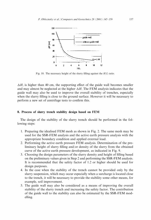
�H, is higher than 40 cm, the supporting e�ect of the guide wall becomes smallerand may almost be neglected at the higher �H. The FEM analysis indicates that theguide wall may also be used to improve the overall stability of trenches, especiallywhen the slurry ®lling is close to the ground surface. However it will be necessary toperform a new set of centrifuge tests to con®rm this.
8. Process of slurry trench stability design based on FEM
The design of the stability of the slurry trench should be performed in the fol-lowing steps:
1. Preparing the idealised FEM mesh as shown in Fig. 2. The same mesh may beused for the SSR-FEM analysis and the active earth pressure analysis with theappropriate boundary condition and applied external load.
2. Performing the active earth pressure FEM analysis. Determination of the pre-liminary height of slurry ®lling and/or density of the slurry from the obtainedcurve of the active earth pressure development, as indicated in Fig. 9.
3. Choosing the design parameters of the slurry density and height of ®lling basedon the preliminary values given in Step 2 and performing the SSR-FEM analysis.It is recommended that the safety factor of 1.2 or higher should be used fordesign purposes.
4. In the case when the stability of the trench cannot be provided only by theslurry suspension, which may occur especially when a surcharge is located closeto the trench, it will be necessary to provide the stability some other means, forexample, soil improvement.
5. The guide wall may also be considered as a means of improving the overallstability of the slurry trench and increasing the safety factor. The contributionof the guide wall to the stability can also be estimated by the SSR-FEM mod-elling.
Fig. 10. The necessary height of the slurry ®lling against the H/L ratio.
P. Oblozinsky et al. / Computers and Geotechnics 28 (2001) 145±159 157
9. Conclusions
In this paper, a method of assessing slurry trench stability by using the SSR-FEMhas been discussed for practical engineering application, which eventually mayreplace the conventional LEM approach. FEM has a number of advantages overLEM. The constitutive law employed in the FEM procedure enables us to model thesoil behaviour more realistically in many cases. The replacement of the in-situ pressurein the trench with the slurry pressure will cause a reduction of the vertical stress behindthe trench face, which also will a�ect the arching e�ect. In other words, di�erentslurry pressures will result in di�erent redistributions of stresses behind the trenchface and will cause di�erent failure patterns. The SSR-FEM is capable of calculatingthe redistribution of the stress behind the trench face incorporating the 3D e�ect andalso the slurry pressure, while in the LEM one needs to adopt often complicatedassumptions in order to account for the 3D e�ect. Another advantage is that thecritical sliding surface is found automatically. Additionally, the solution o�ersinformation on the strain increment state at any Gaussian point when the soil fails.A minimum value of safety factor of 1.2 has been suggested based on the com-
parison between the centrifuge experiments and the SSR-FEM analyses on slurrytrench stability, in which the soil was modelled as elasto-perfectly-plastic materialwith the Mohr±Coulomb failure criterion and the Drucker±Prager plastic potential.The preliminary parameters of the slurry, �H and sl, can be determined by theactive earth pressure analysis. It was shown that if the stability of the trench isevaluated by the SSR-FEM for these preliminary parameters, a safety factor from0.98 to 1.10 could be expected. Afterwards, the preliminary parameters of slurry canbe adjusted in accordance with the requirement of the minimum value of the safetyfactor.
References
[1] Tanaka T, Ugai K, Kawamura M, Sakajo S, Ohtsu H. Three dimensional ®nite element method
analysis of elasto-plastic problems in soil mechanics. Maruzen, 1996 (in Japanese).
[2] Zienkiewicz OC, Humpheson C, Lewis RW. Associated and non-associated viso-plasticity and plas-
ticity in soil mechanics. Ge otechnique 1975;25(4):671±89.
[3] Naylor DJ. Finite elements and slope stability. In: Numer. Methods in Geomechanics, Proc. NATO
Advanced Study Institute, Lisbon, Portugal, 1981. p. 229±44.
[4] Matsui T, San K-C. Finite element slope stability analysis by shear strength reduction technique. Soil
and Foundation 1992;32(1):59±70.
[5] Ugai K, Leshchinsky D. Three-dimensional limit equilibrium method and ®nite element analysis: a
comparison of results. Soil and Foundation 1995;35(4):1±7.
[6] Dawson EM, Roth WH, Drescher A. Slope stability analysis by strength reduction. Ge otechnique
1999;49(6):833±40.
[7] Nash JKTL, Jones GK. The support of trenches using ¯uid mud. In: Proc. the symposium on grouts
and drilling muds in engineering practice. London: Butterworths, 1963. p. 177±80.
[8] Morgenstern N, Amir-Tahmasseb I. The stability of a slurry trench in cohesionless soil. Ge otechni-
que 1965;15(4):378±95.
[9] Elson WK. An Experimental Investigation of the Stability of Slurry trenches. Ge otechnique
1968;18(1):37±49.
158 P. Oblozinsky et al. / Computers and Geotechnics 28 (2001) 145±159
[10] Piaskowski A, Kowalewski Z. Application of thixotropic clay suspension for stability of vertical
sides of deep trenches without strutting. In: Proc. of 6th International Conference on Soil Mechanics
and Foundation Engineering, vol. 2, Montreal, 1965. p. 526±9.
[11] Washbourne J. The tree dimensional stability analysis of diaphragm wall excavation. Ground Engi-
neering 1984;17(4):24±9.
[12] Tsai J-S, Chang J-C. Three-dimensional stability analysis for slurry-®lled trench wall in cohesionless
soil. Can Geotech J 1996;33:798±806.
[13] Hudey J, Stability of bentonite slurry trenches with some experience in Swiss practice. In: Proc. 5th
European Conference on Soil Mechanics and Foundation Engineering, vol. IV-9, Madrid, 1972. p.
517±22.
[14] Terzaghi K. Theoretical soil mechanics. New York: John Wiley & Sons, Inc, 1943.
[15] Katagiri M, Saitoh K, Masuda T, Aizawa F, Ugai K. Shape e�ect on deformation behaviour and
stability of slurry trench walls constructed in sandy ground. In: Proc. IS-Nagoya '97, Tokyo. Perga-
mon, 1997. p. 665±70.
[16] Katagiri M, Saitoh K, Masuda T, Aizawa F, Ugai K. Measurement of the con®ning pressure around
slurry trenches in sandy ground, In: Proc. Centrifuge '98, Tokyo. Balkena, 1998, p. 655±60.
P. Oblozinsky et al. / Computers and Geotechnics 28 (2001) 145±159 159