a design model for strain-softening and …isi... · a design model for strain-softening and...
TRANSCRIPT
A DESIGN MODEL FOR STRAIN-SOFTENING AND STRAIN-HARDENING FIBER REINFORCED
ELEMENTS REINFORCED LONGITUDINALLY WITH STEEL AND FRP BARS
Mahsa Taheri 1, Joaquim A. O. Barros 2, Hamidreza Salehian 3
1Researcher, Dep. Civil Eng., Minho University, Guimarães, Portugal, [email protected]
2Associate Prof., ISISE, Dep. Civil Eng., Minho University, Guimarães, Portugal, [email protected], corresponding
Author
3PhD Student, ISISE, Dep. Civil Eng., Minho University, Guimarães, Portugal, [email protected]
Abstract
A close form solution is developed for the prediction of the moment-curvature relationship of cross sections of fiber
reinforced concrete (FRC) elements failing in bending, and reinforced longitudinally with steel and fiber reinforced
polymer (FRP) bars. The FRP bars are installed with the largest possible internal arm, e.g. with the minimum concrete
cover that assures the bond conditions for a sound stress transfer from FRC to the FRP bars. The model is also able of
simulating the flexural strengthening contribution provided by FRP bars installed according to the Near Surface Mounted
(NSM) technique. To have good protection conditions against corrosion, the steel bars are applied with a relatively thick
FRC cover. Since steel stirrups are the reinforcement with the smaller concrete cover thickness, they are the most
susceptible to corrosion. In the reinforcement concept to be developed in the present research program, steel stirrups are
replaced with discrete fibers. This hybrid reinforcement aims to develop high durable pre-fabricated elements that fail in
bending. The proposed analytical formulation can simulate FRC with strain softening or strain hardening behavior. In the
present work, the formulation is described and its predictive performance is appraised.
Keyword: A. Discontinuous reinforcement; A. Fibres; A. Hybrid; C. Analytical modeling; flexural reinforcement
2
1. INTRODUCTION
Corrosion of the steel reinforcement (SR) of concrete structures is the main material pathology responsible for the huge
amounts of resources spent in the rehabilitation of the built infrastructure. The corrosion of SR can be caused by a
deficient concrete quality, a too small concrete cover, inadequate construction practices, design inaccuracies, an improper
maintenance of the buildings and an unexpected high level of aggressiveness of environmental agents. As a consequence
of the SR corrosion, the sound cross sectional area decreases, the concrete cover spalls, the concrete cross sectional area
diminishes and the concrete strength decreases. This leads to a decrease of the load carrying capacity of the reinforced
concrete (RC) member, which can affect the structural safety. Therefore, all the strategies that can avoid the occurrence of
corrosion of the reinforcement systems applied in concrete structural elements are of paramount importance in terms of
decreasing the maintenance costs of these structures. This contributes decisively for the development of a new generation
of high durable and sustainable RC buildings.
The present work is part of a research project aiming to contribute to the development of a reinforcement system that
combines Fiber Reinforced Polymers (FRP) and steel bars in an optimized arrangement of the bars, using the potentialities
that each material can provide. In fact, non-corrodible FRP bars of high tensile strength, but with brittle behavior, are near
surface mounted, while ductile steel bars have a concrete cover thickness that assures a high protection from the effects of
corrosive agents. The steel reinforcement ratio is also designed in order to guarantee the safety of the structure in case of a
fire occurrence and the consequent loss of FRP reinforcing capacities.
A fiber reinforced concrete (FRC) of high shear strength is used to suppress the necessity of using steel stirrups, to
improve the bond behavior of concrete-FRP and concrete-steel bars, and to increase protection to the steel bars from
corrosive agents.
The replacement of conventional steel reinforcement by FRP bars has been investigated [1-3] to prevent the corrosion
problem and to improve the durability of concrete structures near marine environments, near the ground, in chemical and
other industrial plants, in places where good quality concrete cannot be achieved, and in thin structural elements. In fact,
in comparison with steel, FRP materials have higher resistance to corrosion, and higher strength-to-weight ratio [4].
Furthermore, they are non-electrical conductive and non-magnetic materials. However, the major obstacles of the
application of FRP bars as a reinforcing material for concrete structures are the relatively high initial costs, low modulus
of elasticity, lack of ductility (linear stress-strain diagram up to rupture with no discernible yield point), and absence of
well-consolidated design guidelines [2-4]. Concrete members reinforced with FRP and subjected to bending moments
behave linearly up to cracking, and almost linearly after cracking with a significant lower stiffness [5, 9]. Deflections and
3
strains of concrete members reinforced with FRP bars are generally larger than the homologous members reinforced with
steel bars. This is due to the low modulus of elasticity and the different bond characteristics of the FRP reinforcements [3,
6, 7]. In addition, as a result of a larger crack width and a smaller compressive stress blocks when using FRP bars for the
flexural reinforcement, the shear capacity of FRP-reinforced concrete beams is smaller than in the case of steel-reinforced
concrete beams of same reinforcement ratio [4].
In an attempt to overcome these drawbacks, Aiello and Ombres [8] proposed a combination of FRP and steel
reinforcements for concrete beams. With this combination of the reinforcement materials, and considering the minor
concrete cover required for FRP, an effective solution in terms of durability is obtained by placing the FRP bars near the
outer surface of the tensile zone and steel bars at the inner level of the tensile zone. In terms of structural behavior of the
concrete member, the presence of the steel bars in the above mentioned hybrid reinforcement system contributes
significantly to ductility and stiffness.
The few tests that were executed confirmed this idea. In fact, Tian and Yuan [7] concluded that the deflection of concrete
beams reinforced with FRP and steel bars was smaller than that of beams reinforced with GFRP. Aiello and Ombres [8]
verified that, in comparison with beams exclusively reinforced with FRP bars, the presence of steel bars reduces crack
width and crack spacing values. These studies also indicate that the hybrid reinforcement system (steel and FRP) is a
competitive solution when the long term costs with repairing activities are also taken into account.
Available research [10-14] evidences that steel fibers can replace steel stirrups, especially when high strength concrete is
used, and when beams are relatively shallow [12, 13]. Steel fibers also reduce the width of shear cracks, thus also
contributing to improve concrete durability [14]. Research also shows that up to a maximum crack width of 0.5 mm, steel
fibers are not affected by corrosion [15]. Furthermore, advances in the manufacture technology of synthetic fibers show
that these non-corrodible fibers have high potentialities for the shear resistance of RC elements [16].
In the present work, a close-form solution is developed for the design of cross section elements of FRC reinforced with
longitudinal steel and FRP bars that fail in bending. This model is an extension of the one proposed by Soranakom [17] for
FRC beams failing in bending and reinforced with steel bars. This Author has shown that this reinforcing strategy can be
cost effective. In the present extended model, the contribution of FRP bars is simulated, since the favorable benefits of
using, simultaneously, steel and FRP bars can contribute for the development of cost competitive and durable structural
concrete elements. In Soranakom’s model a strain softening (SS) FRC was simulated when applied simultaneously with
tensile steel bars [17]. In the model to be presented hereafter, the FRC can have strain softening or strain hardening (SH)
post-cracking behavior [18], and can be reinforced with steel bars, FRP bars or both reinforcements. The predictive
4
performance of the model is assessed by using a cross section layer model that takes into account the constitutive laws of
the materials [19]. Using the moment-curvature relationship derived from this model and applying the concepts of the
stiffness method, the force-deflection relationship of statically determinate elements are determined. This numerical
strategy was applied to assess its potentiality for the evaluation of the force-deflection response recorded experimentally in
non-fibrous concrete beams reinforced with longitudinal steel bars and flexurally strengthened with carbon fibre
reinforced polymer (CFRP) laminate strips applied according to the near surface mounted (NSM) technique [19].
2. CONSTITUTIVE LAWS FOR THE INTERVINING MATERIALS
2.1 Tensile and compressive behavior of FRC
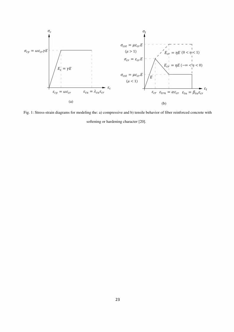
The stress-strain (σ-ε) response for the FRC is based on the model proposed by Soranakom and Mobasher, represented in
Fig. 1 [20]. These diagrams are based on an idealized model indicated by Lim et al. [21] for steel fiber reinforced
concrete. As shown in Fig. 1a, the linear portion of an elastic–perfectly plastic compressive stress–strain response ends at
the pseudo-yield point (���, ���) and remains constant at compressive “yield” stress (���) until the ultimate compressive
strain (���). After this strain limit the concrete strength capacity is assumed null. The concrete stiffness factor ��� represents the ratio between the Young’s modulus of the FRC in compression ��� and in tension ��. In this model � is
the normalized compressive “yield” stress, and ��� is the normalized ultimate compressive strain. As shown in Fig. 1b, the
tensile behavior is described by a trilinear diagram with an elastic range defined by the tensile modulus ��, followed by a
branch characterized by the post-cracking modulus �� � that can be obtained by using a post-crack modulus parameter
���. By attributing to � a negative or a positive value, the same model can be used to simulate strain softening (SS) or
strain hardening (SH) FRC, respectively. At the third region of tensile response, tensile strength remains constant and
equal to ����. The ��� is the normalized ultimate tensile strain, after which the concrete tensile strength capacity is
assumed null. The stress–strain relationship for compression and tension can be expressed as:
������ � ����� �� 0 � �� � �� �� � � ��� � �� � �� � �� � �� ���� �� � � �� � ���0 �� � ���
� (1)
������ � � ��� 0 � �� � ������� ��� � �� � ���0 �� � ��� � (2)
5
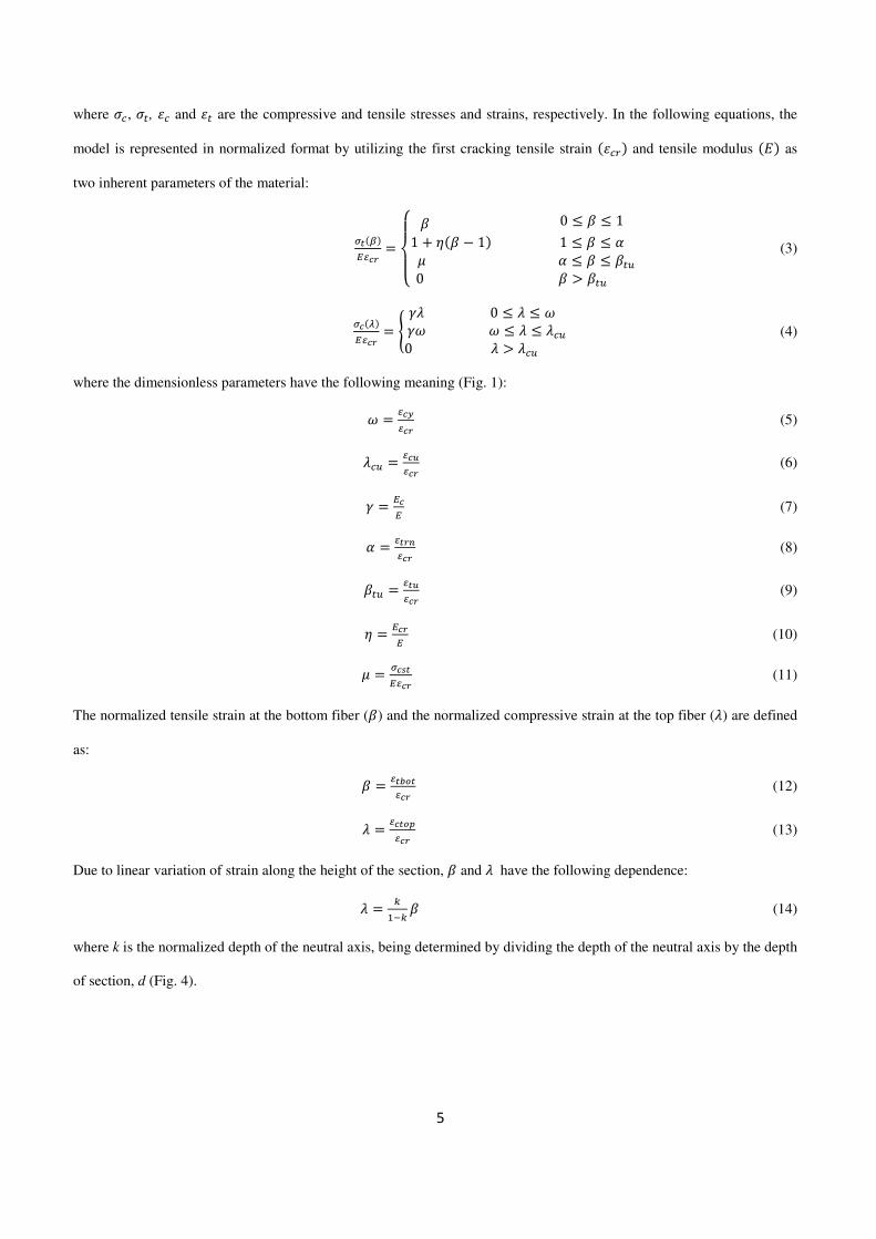
where ��, ��, �� and �� are the compressive and tensile stresses and strains, respectively. In the following equations, the
model is represented in normalized format by utilizing the first cracking tensile strain ��� � and tensile modulus �� as
two inherent parameters of the material:
!�"�#$%& � ����� � 0 � � � 1 1 � ��� � 1� 1 � � � ( � ( � � � ��� 0 � � ���
� (3)
%�)�#$%& � * �� 0 � � � ��� � � � � ���0 � � ��� � (4)
where the dimensionless parameters have the following meaning (Fig. 1):
� � $%+$%& (5)
��� � $%,$%& (6)
� � #%# (7)
( � $!&-$%& (8)
��� � $!,$%& (9)
� � #%&# (10)
� � %.!#$%& (11)
The normalized tensile strain at the bottom fiber (�) and the normalized compressive strain at the top fiber (�) are defined
as:
� � $!/0!$%& (12)
� � $%!01$%& (13)
Due to linear variation of strain along the height of the section, � and � have the following dependence:
� � 2342 � (14)
where k is the normalized depth of the neutral axis, being determined by dividing the depth of the neutral axis by the depth
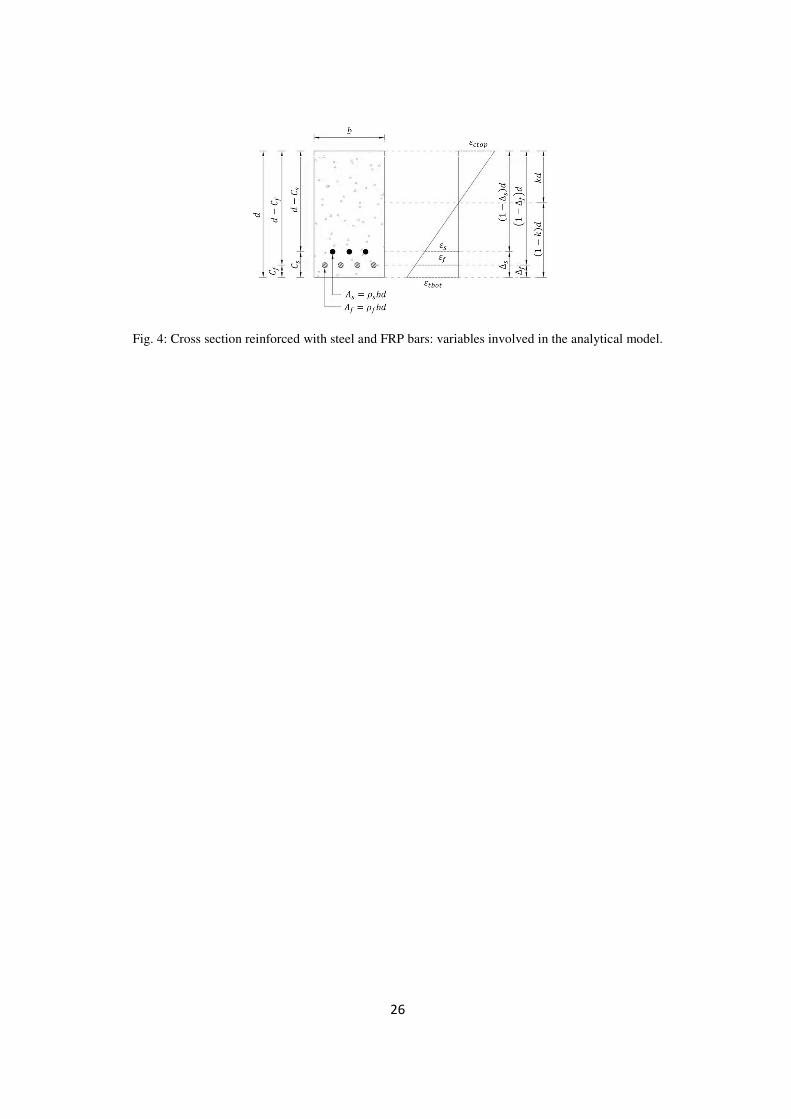
of section, d (Fig. 4).
6
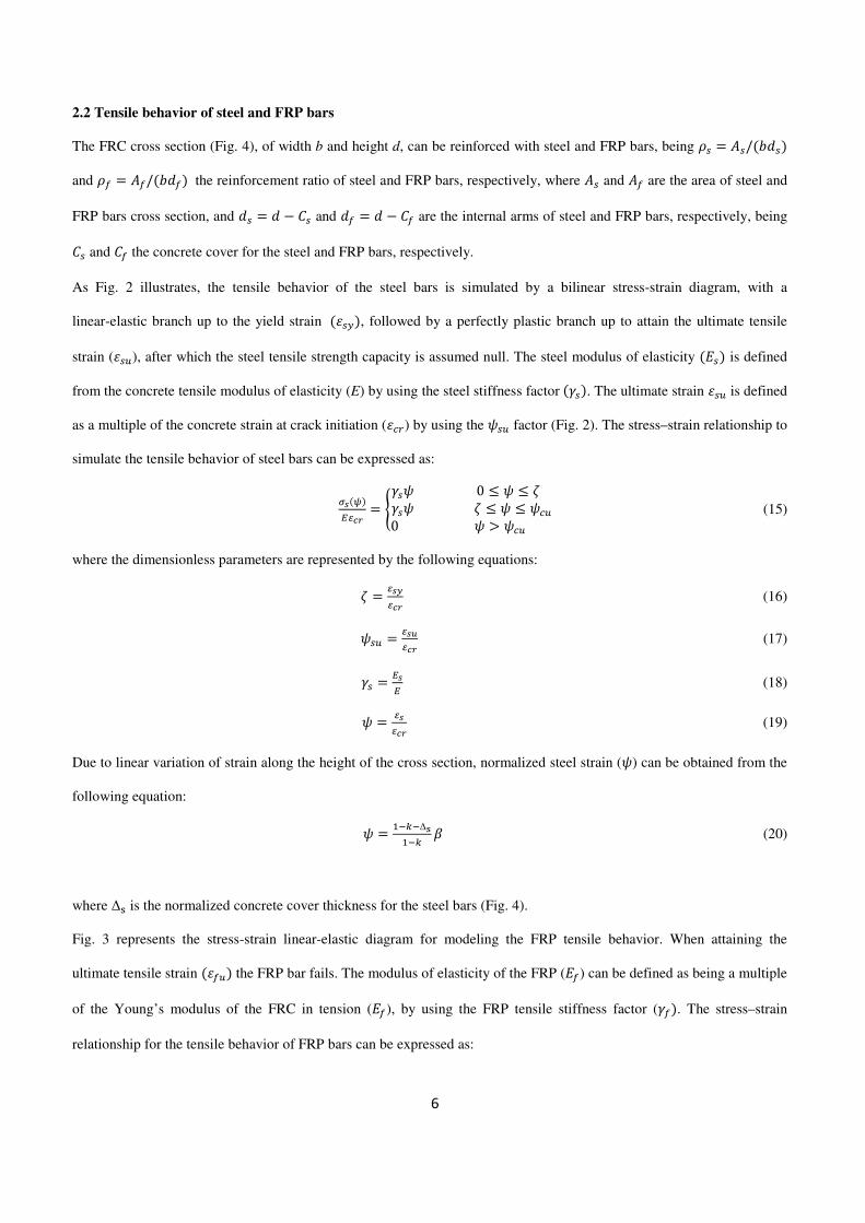
2.2 Tensile behavior of steel and FRP bars
The FRC cross section (Fig. 4), of width b and height d, can be reinforced with steel and FRP bars, being 5� � 6�/�89�� and 5: � 6:/�89:� the reinforcement ratio of steel and FRP bars, respectively, where 6� and 6: are the area of steel and
FRP bars cross section, and 9� � 9 � ;� and 9: � 9 � ;: are the internal arms of steel and FRP bars, respectively, being
;� and ;: the concrete cover for the steel and FRP bars, respectively.
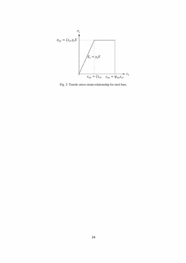
As Fig. 2 illustrates, the tensile behavior of the steel bars is simulated by a bilinear stress-strain diagram, with a
linear-elastic branch up to the yield strain �����, followed by a perfectly plastic branch up to attain the ultimate tensile
strain (���), after which the steel tensile strength capacity is assumed null. The steel modulus of elasticity ��� is defined
from the concrete tensile modulus of elasticity (E) by using the steel stiffness factor ����. The ultimate strain ��� is defined
as a multiple of the concrete strain at crack initiation (�� ) by using the <�� factor (Fig. 2). The stress–strain relationship to
simulate the tensile behavior of steel bars can be expressed as:
.�=�#$%& � *��< 0 � < � >��< > � < � <��0 < � <�� � (15)
where the dimensionless parameters are represented by the following equations:
> � $.+$%& (16)
<�� � $.,$%& (17)
�� � #.# (18)
< � $.$%& (19)
Due to linear variation of strain along the height of the cross section, normalized steel strain (<) can be obtained from the
following equation:
< � 3424∆?342 � (20)
where ∆@ is the normalized concrete cover thickness for the steel bars (Fig. 4).
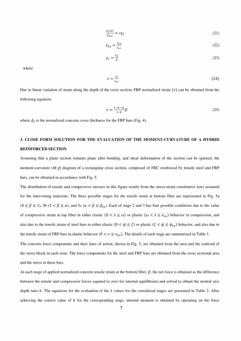
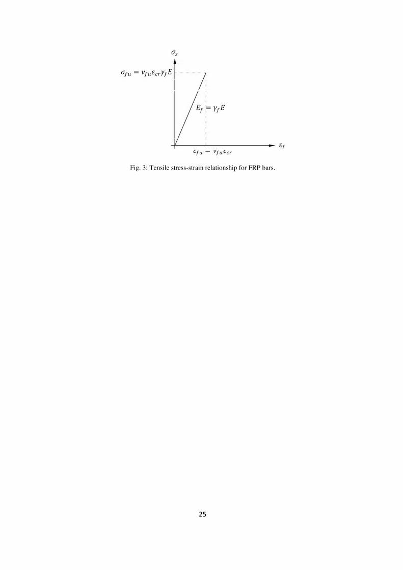
Fig. 3 represents the stress-strain linear-elastic diagram for modeling the FRP tensile behavior. When attaining the
ultimate tensile strain ��:�� the FRP bar fails. The modulus of elasticity of the FRP (:) can be defined as being a multiple
of the Young’s modulus of the FRC in tension (:), by using the FRP tensile stiffness factor (�:�. The stress–strain
relationship for the tensile behavior of FRP bars can be expressed as:
7
A�B�#$%& � ν�: (21)
C:� � $A,$%& (22)
�: � #A# (23)
where
C � $A$%& �24� Due to linear variation of strain along the depth of the cross section, FRP normalized strain �C� can be obtained from the
following equation:
C � 3424∆F342 � (25)
where G: is the normalized concrete cover thickness for the FRP bars (Fig. 4).
3. CLOSE FORM SOLUTION FOR THE EVALUATION OF THE MOMENT-CURVATURE OF A HYBRID
REINFORCED SECTION
Assuming that a plane section remains plane after bending, and shear deformation of the section can be ignored, the
moment-curvature (M-χ) diagram of a rectangular cross section, composed of FRC reinforced by tensile steel and FRP
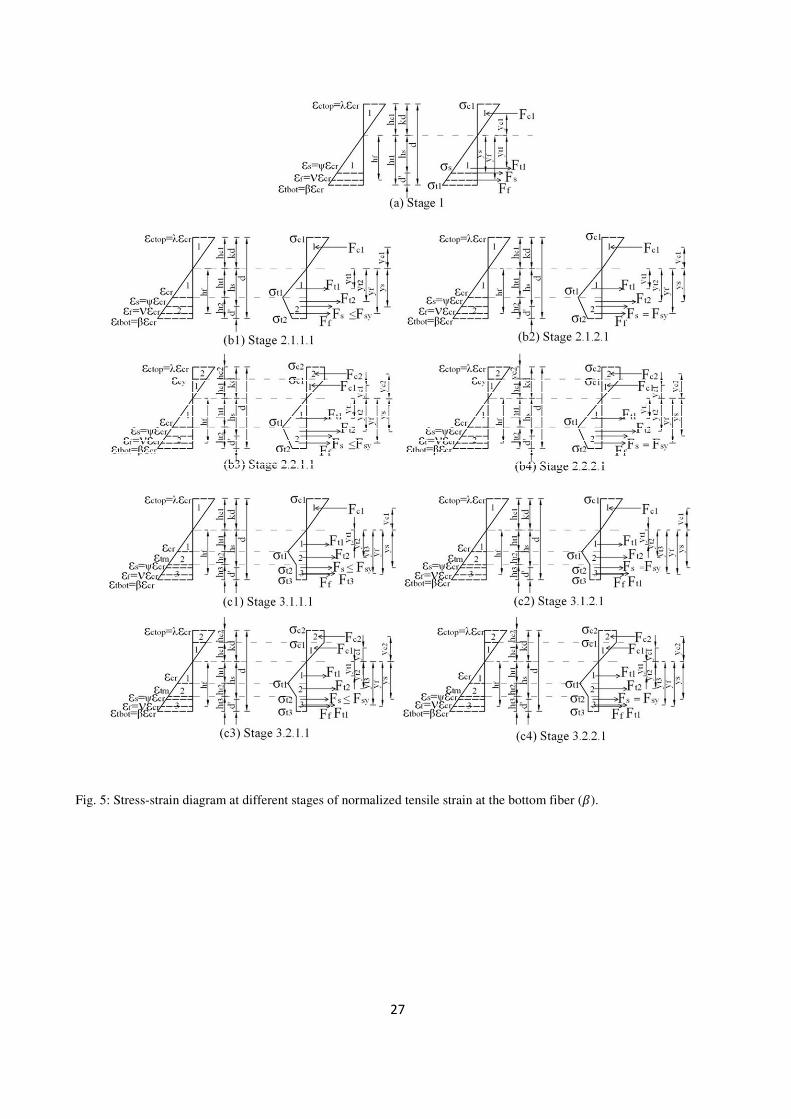
bars, can be obtained in accordance with Fig. 5.
The distribution of tensile and compressive stresses in this figure results from the stress-strain constitutive laws assumed
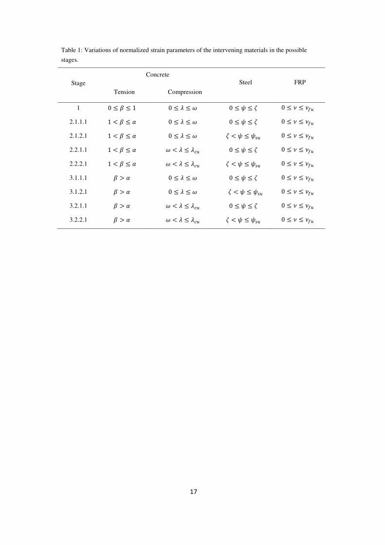
for the intervening materials. The three possible stages for the tensile strain at bottom fiber are represented in Fig. 5a
(0 � � � 1), 5b (1 H � � (), and 5c (( H � � ���). Each of stage 2 and 3 has four possible conditions due to the value
of compressive strain at top fiber in either elastic �0 H � � �� or plastic �� H � � ���� behavior in compression, and
also due to the tensile strain of steel bars in either elastic �0 H < � >� or plastic �> H < � <��� behavior, and also due to
the tensile strain of FRP bars in elastic behavior (0 H C � C:��. The details of each stage are summarized in Table 1.
The concrete force components and their lines of action, shown in Fig. 5, are obtained from the area and the centroid of
the stress block in each zone. The force components for the steel and FRP bars are obtained from the cross sectional area
and the stress in these bars.
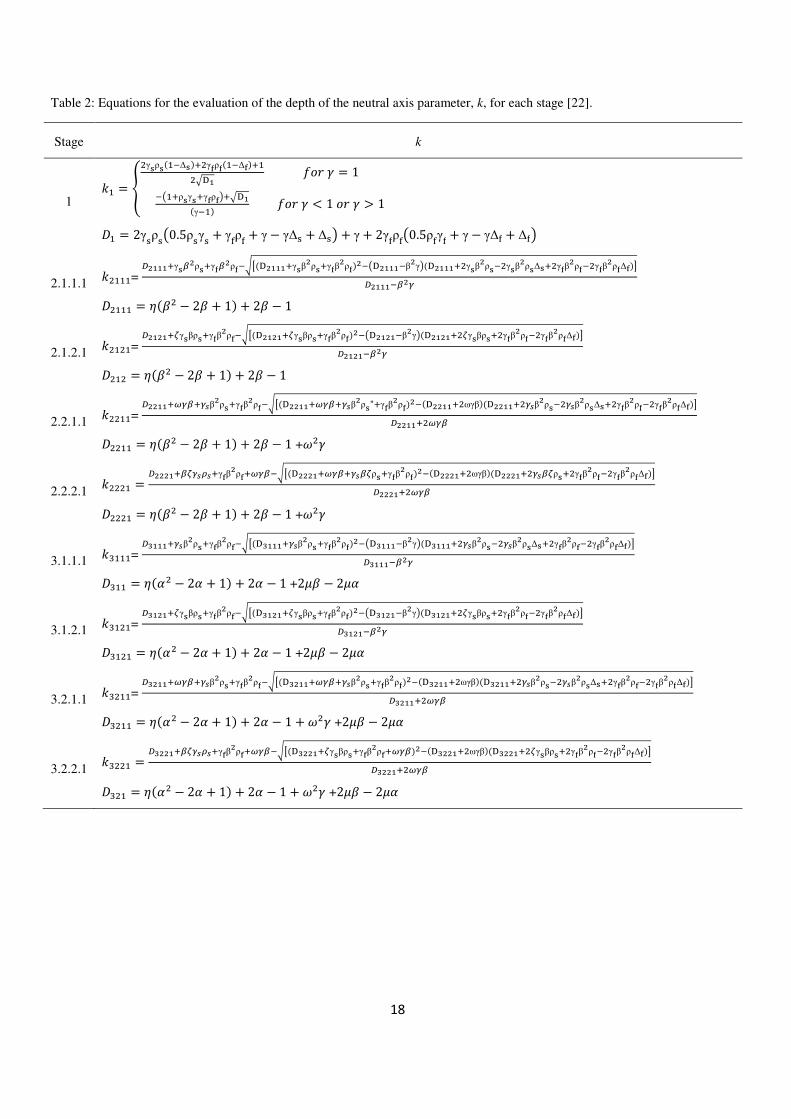
At each stage of applied normalized concrete tensile strain at the bottom fiber, �, the net force is obtained as the difference
between the tensile and compressive forces equated to zero for internal equilibrium and solved to obtain the neutral axis
depth ratio I. The equations for the evaluation of the k values for the considered stages are presented in Table 2. After
achieving the correct value of I for the corresponding stage, internal moment is obtained by operating on the force
8
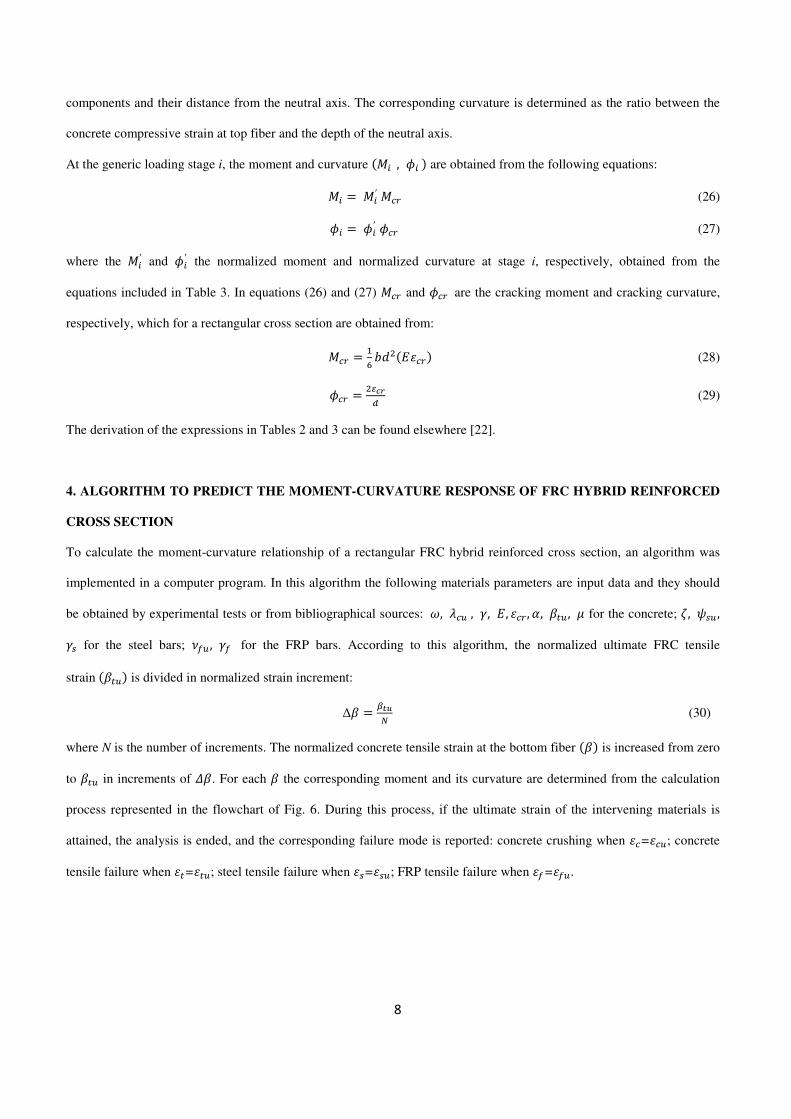
components and their distance from the neutral axis. The corresponding curvature is determined as the ratio between the
concrete compressive strain at top fiber and the depth of the neutral axis.
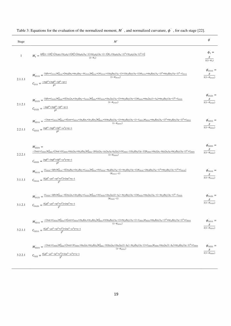
At the generic loading stage i, the moment and curvature �JK , MK � are obtained from the following equations:
JK � JK′ J� (26)
MK � MK′ M� (27)
where the JK′ and MK′ the normalized moment and normalized curvature at stage i, respectively, obtained from the
equations included in Table 3. In equations (26) and (27) J� and M� are the cracking moment and cracking curvature,
respectively, which for a rectangular cross section are obtained from:
J� � 3N 89O��� � (28)
M� � O$%&P (29)
The derivation of the expressions in Tables 2 and 3 can be found elsewhere [22].
4. ALGORITHM TO PREDICT THE MOMENT-CURVATURE RESPONSE OF FRC HYBRID REINFORCED
CROSS SECTION
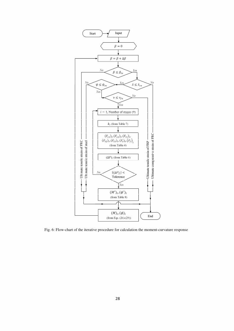
To calculate the moment-curvature relationship of a rectangular FRC hybrid reinforced cross section, an algorithm was
implemented in a computer program. In this algorithm the following materials parameters are input data and they should
be obtained by experimental tests or from bibliographical sources: �, ��� , �, , �� , (, ��� , � for the concrete; >, <�� ,�� for the steel bars; C:� , �: for the FRP bars. According to this algorithm, the normalized ultimate FRC tensile
strain ����� is divided in normalized strain increment:
∆� � "!,Q (30)
where N is the number of increments. The normalized concrete tensile strain at the bottom fiber ��� is increased from zero
to ��� in increments of G�. For each � the corresponding moment and its curvature are determined from the calculation
process represented in the flowchart of Fig. 6. During this process, if the ultimate strain of the intervening materials is
attained, the analysis is ended, and the corresponding failure mode is reported: concrete crushing when ��=���; concrete
tensile failure when ��=���; steel tensile failure when ��=���; FRP tensile failure when �:=�:�.
9
5. MODEL APPRAISAL
To evaluate the accuracy of the proposed formulation, the results obtained from the implemented algorithm are compared
with those determined from the DOCROS software [23]. According to the model implemented in DOCROS, a cross
section is discretized in layers that can have distinct constitutive laws for the characterization of the behavior of the
materials that constitute these layers. A cross section can be composed of plain concrete and FRC layers, and can include
steel and FRP bars. The cross section can be subjected to axial load and increasing curvature. A detailed description of
DOCROS can be found elsewhere [23].
In Table 4 are indicated the values of the geometrical and material parameters for the examples adopted for the assessment
of the predictive performance of the developed formulation.
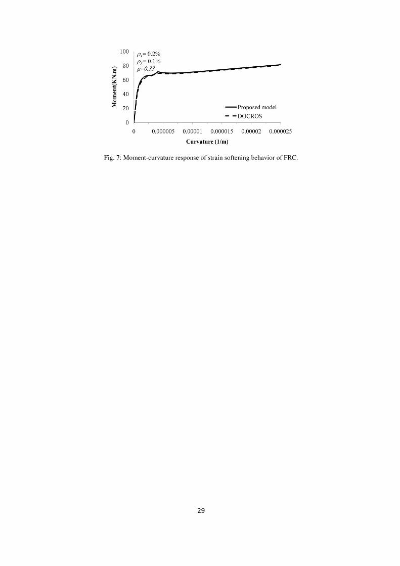
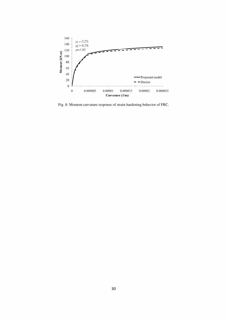
Two types of analysis were performed in order to show the relevance of adopting a strain softening (SS) or a strain
hardening (SH) FRC. The moment-curvature relationships obtained from the present formulation and from DOCROS, for
the case of using a SS-FRC and a SH-FRC, are compared in Figs. 7 and 8, respectively, from which it can be concluded
that the proposed formulation predicts the M-χ with high accuracy. In both analyses the calculation process ended due to
the failing of FRP bars (the ultimate tensile strain was attained). Comparing the diagrams of these both figures it is
verified that an increase of � from 0.33 to 1.00 has provided an increase of 60% in the maximum moment.
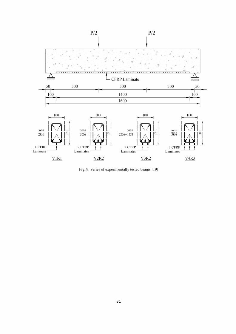
To appraise the capability of the proposed formulation for the case of structural repairing and strengthening applications,
the results of model are compared with those registered in a previous experimental investigation about the use of CFRP
laminate strips applied according to the NSM technique for the flexural strengthening of RC beams [19]. Four series of
beams reinforced with different percentages of tensile longitudinal steel bars with the mean concrete cover of 25 mm, and
also flexurally strengthened with variable number of CFRP strips were tested in a four point loading configuration, see
Fig. 9. This figure also represents the geometry of the beams, the reinforcement arrangement and the number and position
of the CFRP laminates, as well as the loading and the support conditions. The failure mode of the strengthened beams was
characterized by the detachment of a concrete cover that includes the CFRP laminates. Up to near the failure of the beams,
sliding of CFRP was marginal. To simulate the flexural capacity of these beams using the developed model, the CFRP
strips were assumed perfectly bonded to surrounding concrete, and were replaced by equivalent CFRP bars in tensile face
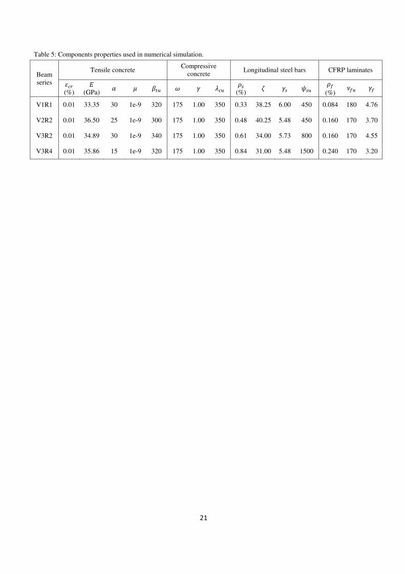
of the section, with a concrete cover of 6.0 mm. Based on available information, the mechanical properties adopted in the
numerical simulations for the intervening materials are indicated in Table 5. Note that an almost null value was assumed
for the normalized post-cracking residual strength (�) to neglect the residual strength of plain concrete in tension after the
linear softening branch (for strain levels above �� �). Small differences exist between the values for the properties of the
10
intervening materials since each series was casted in distinct periods and steel bars of different diameters had distinct
properties.
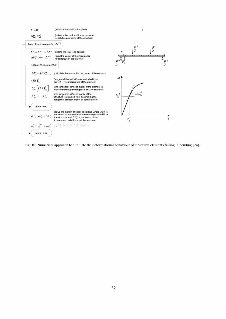
Utilizing the moment-curvature relationships obtained from the proposed model, the force-deflection response of beams
failing in bending can be determined using the algorithm described in Fig. 10 [24]. Comparison between experimental and
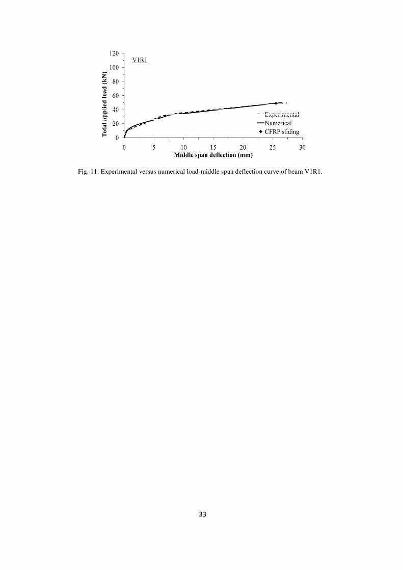
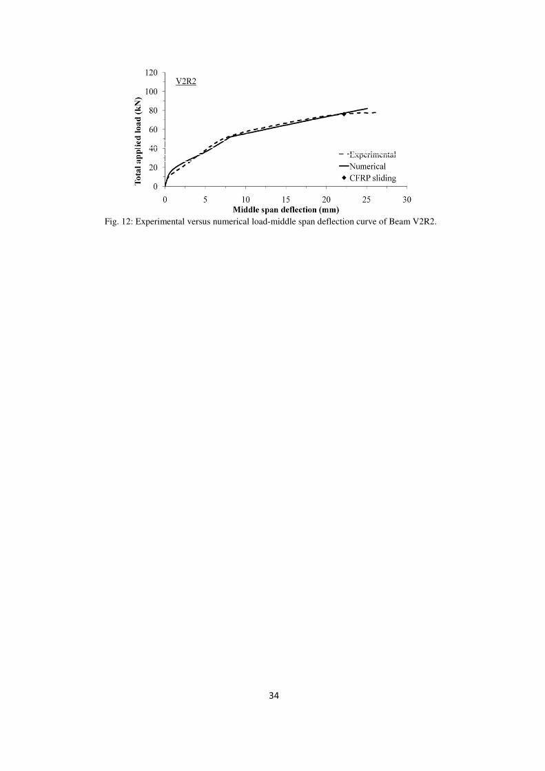
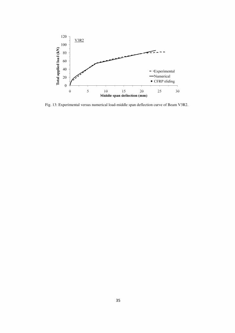
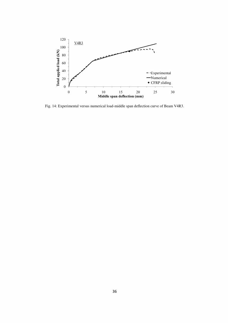
numerical load-middle span deflection relationships are depicted in figures 11 to 14. The points corresponding to CFRP
sliding in the experimental tests are also indicated. As it is observed, the developed numerical strategy is capable of fitting
with enough accuracy the recorded experimental load–middle span deflection curves of each tested beam up to the CFRP
sliding point. After this deflection level, the developed model is no more capable of fitting the experimental response,
since a localized failure mode (rip-off) was formed in the experimentally tested beams, consisting of the detachment of the
concrete cover layer that includes the CFRP laminates [19]. In fact, the numerical curve increases almost linearly, while
the experimental curve shows a gradual decrease of the stiffness of the beam up to its collapse. The deviation of the
numerical curve from the experimental one in its last part (when sliding comes to be significant and rip-off failure mode
starts its formation) increases with the percentage of longitudinal steel and FRP elements, as it would be expected based
on the conclusions already pointed out elsewhere [25]. The maximum strains experimentally registered in the laminates
for the V1R1, V2R2, V3R2 and V4R3 beams at ultimate load were 0.016, 0.013, 0.013 and 0.011, respectively, while the
model predicted the following values: 0.017, 0.015, 0.014, and 0.011, which proves the validity of the FRP-concrete
perfect bond assumption for this type of applications.
6. CONCLUSIONS
The simultaneous use of steel and FRP longitudinal bars for the flexural reinforcement of pre-fabricated fiber reinforced
concrete (FRC) beams is a hybrid reinforcement concept that can contribute to the development of new generation of more
durable concrete structures. The steel and FRP bars are positioned in order to optimize their reinforcing potentialities, to
assure the necessary bond conditions for the FRP bars, and to provide extra protection against corrosion to the steel bars.
Steel stirrups are replaced by discrete fibers, applying a FRC with a post-cracking residual strength that can provide the
required shear resistance. To analyze the flexural potentialities of this concept, an analytical model was developed, and the
equations for the determination of the moment-curvature relationship for a rectangular cross section reinforced according
to this concept are presented in this work. The good predictive performance of the developed model was appraised using a
computer program based on the cross section layer model. The proposed formulation was also utilized in order to simulate
the load-middle deflection response of plain concrete beams reinforced with steel bars and flexurally strengthened with
11
carbon fiber reinforced polymer laminate strips according to the Near Surface Mounted technique. The moment-curvature
relationship was used as the entity capable of supplying the tangential or the secant flexural stiffness of small elements
that discretize a statically determinate beam, in order to predict its force-deflection response. This numerical strategy was
capable of simulating with high accuracy the force-deflection response of this hybrid reinforced beams. This model can
also be used to perform parametric studies for the optimization of the reinforcing systems for given types of beams.
ACKNOWLEDGEMENTS
The study reported in this paper is part of the research programs “DURCOST”, PTDC/ECM/105700/2008, supported by
FCT, and “PONTALUMIS”, QREN, project number 3456. The first and third Authors wish to acknowledge the support
provided by project PONTALUMIS, while the second Author acknowledges the support of DURCOST.
REFERENCES
1. Thériault M, Benmokrane B. Effects of FRP reinforcement ratio and concrete strength on flexural behavior of concrete
beams. Journal of Composites for Construction 1998; 2 (1): 7-16.
2. Toutanji HA, Saafi M. Flexural behavior of concrete beams reinforced with glass fiber-reinforced polymer (GFRP)
bars. ACI Structural Journal 2000; 97 (5): 712-719.
3. Abdalla HA. Evaluation of deflection in concrete members reinforced with fibre reinforced polymer (FRP) bars. Journal
of Composite Structures 2002; 56: 63-71.
4. ACI 440R-07. Report on fiber-reinforced polymer (FRP) reinforcement for concrete structures. American concrete
institute, Reported by ACI committee 440; 2007.
5. Barros JAO, Dias SJE, Lima JLT. Efficacy of CFRP-based techniques for the flexural and shear strengthening of
concrete beams. Cement & Concrete Composites 2007; 29: 203-217.
6. Bakis CE, Bank LC, Brown VL, Cosenza E, Davalos JF, Lesko JJ, Machida A, Riskalla SH, Triantafillou TC. Fiber-
reinforced polymer composites for construction – state-of-the-art review. Journal of Composites for Construction 2002;
6(2): 73-87.
7. Tian Y, Yuan Y. Deflection prediction of concrete beams reinforced with GFRP and steel rods. In: Proceedings (CD-
ROM) of FRPRCS-8 Conference. Patras, July, 2007.
12
8. Aiello MA, Ombres L. Structural performances of concrete beams with hybrid (fiber-reinforced polymer-steel)
reinforcements. Journal of Composites for Construction 2002; 6 (2): 133-140.
9. Leung HY, Balendran RV. Flexural behaviour of concrete beams internally reinforced with GFRP rods and steel rebars.
Structural Survey 2003; 21 (4): 146-157.
10. Santos PFS, Barros JAO, Lourenço LAP. Steel fibres for the shear resistance of high strength concrete beams. In:
Proceeding of BEFIB2008 Conference. Chennai, September, 2008. Paper SIM012008.
11. Barros JAO, Gettu R, Barragan BE. Material nonlinear analysis of steel fibre reinforced concrete beams failing in
shear. In: Proceeding of BEFIB2004 Conference. Varenna, Lake Como, Italy, September, 2004. 711-720.
12. Casanova P. Bétons de fibres métalliques: du matériaux à la structure. PhD Thesis ; École Nationale des Ponts et
Chaussées; 1995 [in French].
13. Casanova P, Rossi P, Schaller I. Can steel fibres replace transverse reinforcement in reinforced concrete beams? ACI
Material Journal 2000; 94: 341-354.
14. Meda A, Minelli F, Plizzari GP, Riva P. Shear behavior of steel fibre reinforced concrete beams. Materials and
Structures Journal 2005; 38: 343-353.
15. Barros JAO, Pereira EB, Cunha VMCF, Ribeiro AF, Santos SPF, Queirós PAAAV. PABERFIA-Lightweight
sandwich panels in steel fiber reinforced self compacting concrete. Technical Report 05-DEC/E-29, Department of Civil
Engineering, School of Engineering, University of Minho, 2005, 63 pages.
16. Furlan S, Hanai JB. Shear behaviour of fiber reinforced concrete beams. Cement and Concrete Composites 1998;
19(4): 359-366.
17. Soranakom C., Multi scale modeling of fibre and fabric reinforced cement based composites, PhD thesis, Arizona
State University, 2008.
18. Naaman AE, Reinhard H. Proposed classification of HPFRC composites based on their tensile response. Materials and
Structures 2006; 39: 547-555.
19. Barros JAO, Fortes AS. Flexural strengthening of concrete beams with CFRP laminates bonded into slits. Cement &
Concrete Composites 2005; 27(4): 471-480.
20. Soranakom C, Mobasher B. Correlation of tensile and flexural response of strain softening and strain hardening
cement composites. Cement & Concrete Composites 2008; 30: 465-477.
13
21. Lim TY, Paramasivam P, Lee SL. Analytical model for tensile behavior of steel-fiber concrete. ACI Material Journal
1987; 84(4): 286-551.
22. Taheri M, Barros JAO, Salehian HR. A design model for strain-softening and strain-hardening fiber reinforced
elements reinforced by longitudinal steel bars and strengthened by FRP bars failing in bending. Technical report 16-
DEC/E-10, Department of Civil Engineering, School Engineering, University of Minho, 2010, 44 pages.
23. Basto CAA, Barros JAO. Numeric simulation of sections submitted to bending. Technical report 08-DEC/E-46,
Department of Civil Engineering, School Engineering, University of Minho, 2008, 73 pages.
24. Barros J.A.O., Oliveira J.T., Lourenço P.J.B., Bonaldo E., Flexural behavior of reinforced masonry panels, ACI
Structural Journal 2006; 13(3): 418-426.
25. Barros JAO, Kotynia R. Possibilities and challenges of NSM for the flexural strengthening of RC structures. In
Proceeding of CICE2008 Conference. Zurich, 2008.
14
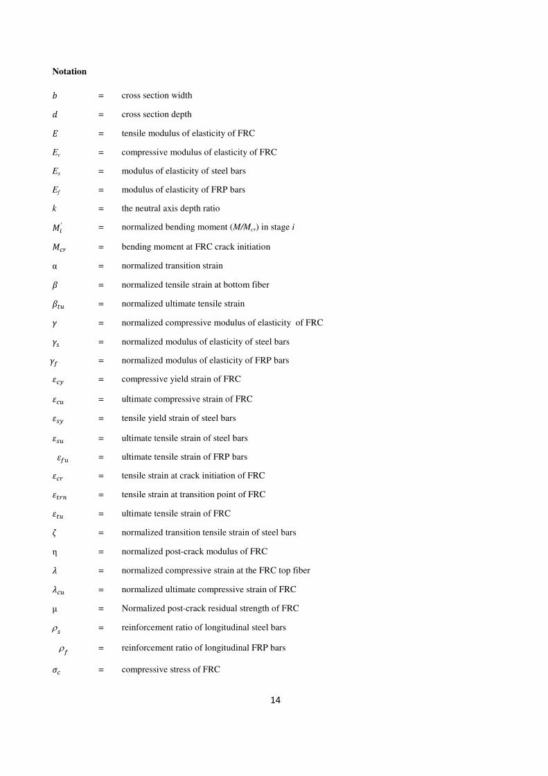
Notation
8 = cross section width 9 = cross section depth = tensile modulus of elasticity of FRC
Ec = compressive modulus of elasticity of FRC
Es
Ef
=
=
modulus of elasticity of steel bars
modulus of elasticity of FRP bars
k = the neutral axis depth ratio JK′ = normalized bending moment (M/Mcr) in stage i
J� = bending moment at FRC crack initiation
α = normalized transition strain � = normalized tensile strain at bottom fiber ��� = normalized ultimate tensile strain � = normalized compressive modulus of elasticity of FRC �� �:
=
=
normalized modulus of elasticity of steel bars
normalized modulus of elasticity of FRP bars ��� = compressive yield strain of FRC
��� = ultimate compressive strain of FRC ��� = tensile yield strain of steel bars
��� �:� =
=
ultimate tensile strain of steel bars
ultimate tensile strain of FRP bars �� = tensile strain at crack initiation of FRC �� � = tensile strain at transition point of FRC ��� = ultimate tensile strain of FRC > = normalized transition tensile strain of steel bars
η = normalized post-crack modulus of FRC � = normalized compressive strain at the FRC top fiber ��� = normalized ultimate compressive strain of FRC
µ = Normalized post-crack residual strength of FRC
ρ� = reinforcement ratio of longitudinal steel bars
ρ: = reinforcement ratio of longitudinal FRP bars
�� = compressive stress of FRC
15
�� = tensile stress of FRC �� �:
=
=
tensile stress of the steel bars
tensile stress of the FRP bars ���� = residual tensile stress of FRC M� = curvature at crack initiation of FRC
MK′ = normalized curvature M/M�
< = normalized tensile strain of steel bars <�� = normalized ultimate steel tensile strain of steel bars � = normalized compressive yield strain of FRC
∆@ = normalized cover thickness of steel bars
∆R = normalized cover thickness of FRP bars ν = normalized tensile strain of FRP bars ν:� = normalized ultimate tensile strain of FRP bars

16
LIST OF TABLE CAPTIONS
Table 1: Variations of normalized strain parameters of the intervening materials in the possible stages.
Table 2: Equations for the evaluation of the depth of the neutral axis parameter, k, for each stage [22].
Table 3: Equations for the evaluation of the normalized moment, J´ , and normalized curvature, M´ , for each stage [22].
Table 4: Data for the model parameters used in the examples for the assessment of the predictive performance of the
developed model.
Table 5: Components properties used in numerical simulation.
17
Table 1: Variations of normalized strain parameters of the intervening materials in the possible
stages.
Stage Concrete
Steel FRP
Tension Compression
1 0 � � � 1 0 � � � � 0 � < � > 0 � C � C:�
2.1.1.1 1 H � � ( 0 � � � � 0 � < � > 0 � C � C:�
2.1.2.1 1 H � � ( 0 � � � � > H < � <�� 0 � C � C:�
2.2.1.1 1 H � � ( � H � � ��� 0 � < � > 0 � C � C:�
2.2.2.1 1 H � � ( � H � � ��� > H < � <�� 0 � C � C:�
3.1.1.1 � � ( 0 � � � � 0 � < � > 0 � C � C:�
3.1.2.1 � � ( 0 � � � � > H < � <�� 0 � C � C:�
3.2.1.1 � � ( � H � � ��� 0 � < � > 0 � C � C:�
3.2.2.1 � � ( � H � � ��� > H < � <�� 0 � C � C:�
18
Table 2: Equations for the evaluation of the depth of the neutral axis parameter, k, for each stage [22].
Stage k
1 I3 � TOγ?ρ?�34∆?�UOγFρF�34∆F�U3OVWX YZ[ � � 1
4\3Uρ?γ?UγFρF]UVWX�γ43� YZ[ � H 1 Z[ � � 1� 3 � 2γ@ρ@\0.5ρ@γ@ � γRρR � γ� γ∆@ � ∆@] � γ� 2γRρR\0.5ρRγR � γ� γ∆R � ∆R]
2.1.1.1 IO333= abXXXUγ?"bρ?UγF"bρF4cd�WbXXXUγ?βbρ?UγFβbρF�b4\WbXXX4βbγ]�WbXXXUOγ?βbρ?4Oγ?βbρ?∆?UOγFβbρF4OγFβbρF∆F�eabXXX4"bf
O333 � ���O � 2� � 1� � 2� � 1
2.1.2.1 IO3O3= abXbXUgγ?βρ?UγFβbρF4cd�WbXbXUgγ?βρ?UγFβbρF�b4\WbXbX4βbγ]�WbXbXUOgγ?βρ?UOγFβbρF4OγFβbρF∆F�eabXbX4"bf
O3O � ���O � 2� � 1� � 2� � 1
2.2.1.1 IOO33= abbXXUhf"Uf.βbρ?UγFβbρF4cd�WbbXXUhf"Uf.βbρ?"UγFβbρF�b4�WbbXXUOωγβ��WbbXXUOf.βbρ?4Of.βbρ?∆?UOγFβbρF4OγFβbρF∆F�eabbXXUOhf"
OO33 � ���O � 2� � 1� � 2� � 1 +�O�
2.2.2.1 IOOO3 � abbbXU"gf.j.UγFβbρFUhf"4cd�WbbbXUhf"Uf."gρ?UγFβbρF�b4�WbbbXUOωγβ��WbbbXUOf."gρ?UOγFβbρF4OγFβbρF∆F�eabbbXUOhf"
OOO3 � ���O � 2� � 1� � 2� � 1 +�O�
3.1.1.1 Ik333= alXXXUf.βbρ?UγFβbρF4cd�WlXXXUf.βbρ?UγFβbρF�b4\WlXXX4βbγ]�WlXXXUOf.βbρ?4Of.βbρ?∆?UOγFβbρF4OγFβbρF∆F�ealXXX4"bf
k33 � ��(O � 2( � 1� � 2( � 1 +2�� � 2�(
3.1.2.1 Ik3O3= alXbXUgγ?βρ?UγFβbρF4cd�WlXbXUgγ?βρ?UγFβbρF�b4\WlXbX4βbγ]�WlXbXUOgγ?βρ?UOγFβbρF4OγFβbρF∆F�ealXbX4"bf
k3O3 � ��(O � 2( � 1� � 2( � 1 +2�� � 2�(
3.2.1.1 IkO33= albXXUhf"Uf.βbρ?UγFβbρF4cd�WlbXXUhf"Uf.βbρ?UγFβbρF�b4�WlbXXUOωγβ��WlbXXUOf.βbρ?4Of.βbρ?∆?UOγFβbρF4OγFβbρF∆F�ealbXXUOhf"
kO33 � ��(O � 2( � 1� � 2( � 1 � �O� +2�� � 2�(
3.2.2.1 IkOO3 � albbXU"gf.j.UγFβbρFUhf"4cd�WlbbXUgγ?βρ?UγFβbρFUhf"�b4�WlbbXUOωγβ��WlbbXUOgγ?βρ?UOγFβbρF4OγFβbρF∆F�ealbbXUOhf"
kO3 � ��(O � 2( � 1� � 2( � 1 � �O� +2�� � 2�(
19
Table 3: Equations for the evaluation of the normalized moment, J´ , and normalized curvature, M´ , for each stage [22].
Stage M´ M´
1 J3´ � O"d�f43�nXlU\kf.j.UkfAjAUk]nXbU\Nf.j.�∆?43�UNfAjA�∆F43�4k]nXUkf.j.�∆?43�bUkfAjA�∆F43�bU3e�34nX� M3´ �"O�34nX�
2.1.1.1 JO333´ � �O"fUobXXX�nbXXXl U\Nf."j.UNfA"jA4kobXXX]nbXXXb U�kobXXXU3Of."j.�∆?43�U3OfA"jA�∆F43��nbXXXUNf."j.�∆?43�bUNfA"jA�∆F43�b4obXXX�34nbXXX�
;O33 � 4Op"lUkp"b4k"b4pU3"b
MO333´ �"O�34nbXXX�
2.1.2.1 JO3O3´ � �O"fUobXbX�nbXbXl Uk\Of.gj.UOfA"jA4obXbX]nbXbXb Uk�obXbXUOf.gj.�∆?4O�UqfA"jA�∆F43��nbXbXUNf.gj.�34∆?�UNfA"jA�∆F43�b4obXbX�34nbXbX�
;O3O3 � 4Op"lUkp"b4k"b4pU3"b
MO3O3´ �"O�34nbXbX�
2.2.1.1
JOO33´ � 4�khfUobbXX�nbbXXl Uk\hfUobbXXUOf."j.UOfA"jA]nbbXXb Uk�qf."j.�∆?43�UqfA"jA�∆F43�4obbXX�nbbXXUNf."j.�∆?43�bUNfA"jA�∆F43�bUobbXX�34nbbXX�
;OO33 � Op"l4kp"bUk"b4hlfUp43"b
MOO33´ �"O�34nbbXX�
2.2.2.1
JOOO3´ �4�khfUobbbX�nbbbXl U\khfUOobbbXUNf.gj.UNfA"jA]nbbbXb 4rN�f.gj.4f.gj.∆?Uf.gj.�UkobbbX43OfA"jA�∆F43�snbbbXUNf.gj.4Nf.gj.∆?UNfA"jA�∆F43�bUobbbX�34nbbbX�
;OOO3 � Op"l4kp"bUk"b4hlfUp43"b
MOOO3´ �"O�34nbbbX�
3.1.1.1
Jk333´ � �olXXX4O"f�nlXXXl 4k\Of."j.UOfA"jAUolXXX]nlXXXb Uk�olXXX4qf."j.�∆?43�4qfA"jA�∆F43��nlXXX4�Nf."j.�∆?43�bUNfA"jA�∆F43�bUolXXX��nlXXX43�
Ck333 � k\µβb4µαb4ηαbUαb]UOηαlUη43βb
Mk333´ �"O�34nlXXX�
3.1.2.1
Jk3O3´ � �olXbX4O"f�nlXbXl 4k\Of.gj.UOfA"jAUolXbX]nlXbXb Uk�olXbXUOf.gj.�O4∆?�4qfA"jA�∆F43��nlXbXUNf.gj.�∆?43�4NfA"jA�∆F43�b4olXbX�nlXbX43�
Ck3O3 � k\µβb4µαb4ηαbUαb]UOηαlUη43βb
Mk3O3´ �"O�34nlXbX�
3.2.1.1
JkO33´ � 4�khfUolbXX�nlbXXl Uk\hfUolbXXUOf."j.UOfA"jA]nlbXXb Uk�qf."j.�∆?43�UqfA"jA�∆F43�4olbXX�nlbXXUNf."j.�∆?43�bUNfA"jA�∆F43�bUolbXX�34nlbXX�
CkO33 � k\µβb4µαb4ηαbUαb]UOηαl4hlfUη43βb
MkO33´ �"O�34nlbXX�
3.2.2.1
JkOO3´ � 4�khfUolbbX�nlbbXl U\khfUkolbbXUNf.gj.UNfA"jA]nlbbXb 4k�Of.gj.UOf.gj.�34∆.�4qfA"jA�∆F43�UolbbX�nlbbXUNf.gj.�34∆.�UNfA"jA�∆F43�bUolbbX�34nlbbX�
CkOO � k\µβb4µαb4ηαbUαb]UOηαl4hlfUη43βb
MkOO3´ �"O�34nlbbX�

20
Table 4: Data for the model parameters used in the examples for the assessment of the predictive performance of the developed model.
Geometric parameter
(mm)
Mechanical parameters
Concrete (tension) Concrete
(compression) Steel (tension)
FRP (tension)
b
d
250
500 �� (%)
(GPa)
( ��� �* �** �* �** � � ��� > �� <�� C:� �:
Cs
Cf
80
50 1e-4 30 10 150 1.00 0.33 -0.074 0.0 10 1 40 12 10 120 120 1
* For strain softening FRC ** For strain hardening FRC
21
Table 5: Components properties used in numerical simulation.
Beam series
Tensile concrete Compressive
concrete Longitudinal steel bars CFRP laminates ��
(%)
(GPa) ( � ��� � � ���
5� (%)
> �� <�� 5:
(%) C:� �:
V1R1 0.01 33.35 30 1e-9 320 175 1.00 350 0.33 38.25 6.00 450 0.084 180 4.76
V2R2 0.01 36.50 25 1e-9 300 175 1.00 350 0.48 40.25 5.48 450 0.160 170 3.70
V3R2 0.01 34.89 30 1e-9 340 175 1.00 350 0.61 34.00 5.73 800 0.160 170 4.55
V3R4 0.01 35.86 15 1e-9 320 175 1.00 350 0.84 31.00 5.48 1500 0.240 170 3.20
22
LIST OF FIGURE CAPTIONS
Fig. 1: Stress-strain diagrams for modeling the: a) compressive and b) tensile behavior of fiber reinforced concrete with
softening or hardening character [20].
Fig. 2: Tensile stress-strain relationship for steel bars.
Fig. 3: Tensile stress-strain relationship for FRP bars.
Fig 4: Cross section reinforced with steel and FRP bars: variables involved in the analytical model.
Fig. 5: Stress-strain diagram at different stages of normalized tensile strain at the bottom fiber (�).
Fig. 6: Flow-chart of the iterative procedure for calculation the moment-curvature response
Fig. 7: Moment-curvature response of strain softening behavior of FRC.
Fig. 8: Moment-curvature response of strain hardening behavior of FRC.
Fig. 9: Series of experimentally tested beams [19]
Fig. 10: Numerical approach to simulate the deformational behaviour of structural elements failing in bending [24].
Fig. 11: Experimental versus numerical load-middle span deflection curve of beam V1R1.
Fig. 12: Experimental versus numerical load-middle span deflection curve of Beam V2R2. Fig. 13: Experimental versus numerical load-middle span deflection curve of Beam V3R2. Fig. 14: Experimental versus numerical load-middle span deflection curve of Beam V4R3.
23
(a)
(b)
Fig. 1: Stress-strain diagrams for modeling the: a) compressive and b) tensile behavior of fiber reinforced concrete with
softening or hardening character [20].
24
Fig. 2: Tensile stress-strain relationship for steel bars.
25
Fig. 3: Tensile stress-strain relationship for FRP bars.
26
Fig. 4: Cross section reinforced with steel and FRP bars: variables involved in the analytical model.
27
Fig. 5: Stress-strain diagram at different stages of normalized tensile strain at the bottom fiber (�).
28
Fig. 6: Flow-chart of the iterative procedure for calculation the moment-curvature response
29
Fig. 7: Moment-curvature response of strain softening behavior of FRC.
30
Fig. 8: Moment-curvature response of strain hardening behavior of FRC.
31
Fig. 9: Series of experimentally tested beams [19]
32
/
Fig. 10: Numerical approach to simulate the deformational behaviour of structural elements failing in bending [24].
33
Fig. 11: Experimental versus numerical load-middle span deflection curve of beam V1R1.
34
Fig. 12: Experimental versus numerical load-middle span deflection curve of Beam V2R2.
35
Fig. 13: Experimental versus numerical load-middle span deflection curve of Beam V3R2.
36
Fig. 14: Experimental versus numerical load-middle span deflection curve of Beam V4R3.