a digitally fabricated house for new orleans - … · a digitally fabricated house for new orleans...
TRANSCRIPT
1
A digitally fabricated house for New Orleans Lawrence Sass
Department of Architecture
Massachusetts Institute of Technology
Key words: Digital Fabrication, Housing, Design Computing
Abstract
This report is a conceptual illustration of building construction with digital fabrication
machinery. It demonstrates the purpose and potential of digital fabrication with structures
fabricated of plywood. A method is prescribed and demonstrated to build a small
structure in the form of a shotgun house for New Orleans, the structure and its application
is evidence of the new possibilities. Most important is this report outlines a theory that all
buildings can be produced with digitally fabrication as highly precise products ready for
new application and diverse styles.
1. Personalized design localized fabrication Home design and construction of high quality, low energy and low cost could be
coming soon to a neighborhood near you. These homes will be built anew, replace older
energy consuming houses or replace houses destroyed by natural disaster. These houses
will be manufactured from data generated with CAD (Computer Aided Design) software
then manufactured by computer controlled machinery. Digital fabrication is computers
and CNC (computer numerically controlled) machinery from data generated in CAD
software, the results are physical products of all sizes from small models to buildings.
Although digital fabrication is an emerging area in the field of architecture it has yet to
have an effect on the physical production of buildings outside the circles of the boutique
architects.
Potential applications for digital fabrication is vast it is compact manufacturing
ready for today’s energy needs. Possible is physical production of new forms of localized
manufacturing with small fast machinery as a reaction to the century old concept of
prefabricated construction. In contrast to digital fabrication, prefabricated housing means
large factories, energy consuming ground transportation of panels and boxes and gas
guzzling cranes. For a century they have been responsible for a variety of ways to
produce large wood boxes from expensive startups. For the creative class digital
fabrication supports the concept of mass production and customized craft also defined as
mass customization1. It will make possible a variety of designs shapes and details within
reach of low end home buyers.
Digital fabrication also opens the possibility for manufacturing of building
products by trades within local and national reach. High tech, energy efficient products
can be made offsite as custom objects with an assured fit with locally fabricated homes.
With this technology will come methods to produce building chunks delivered to the site
for assembly of a building complete with mechanical, electrical and solar systems2. Of
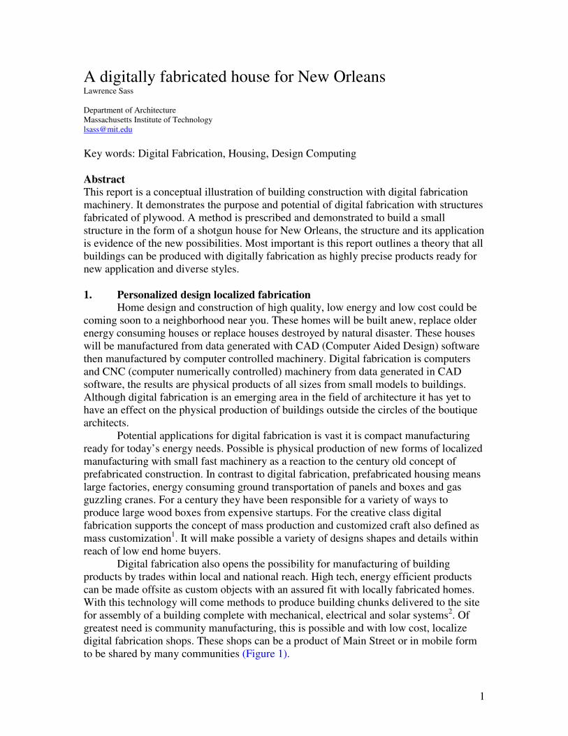
greatest need is community manufacturing, this is possible and with low cost, localize
digital fabrication shops. These shops can be a product of Main Street or in mobile form
to be shared by many communities (Figure 1).
2
Figure 1 a mobilize fabrication facility built at MIT summer 2007
1.1 A digitally fabricated home
An example of a digitally fabricated home/structure was produced for exhibition
at the Modern Museum of Art (MoMA) in New York City. The exhibit, entitled Home
Delivery was a presentation of prefabricated housing with selected past, present and
future displays3. The example in figure 2 is one of five full scale homes in the exhibit. Of
the five buildings three used digital fabrication as the primary means of physical
production. Previous professional examples and purposes for digital fabrication have
focused on complex geometrical outcomes4,5. Alternatively the design goal here was
reconstruction of a New Orleans shotgun house complete with ornamentation as a way to
illustrate diverse possibilities. The structure was on display in an empty lot adjacent the
museum grounds for four months - summer and fall of 2008. Both inside and out the
exhibit structure had to sustain 20-30 visitors at a time while resisting the elements of
nature (wind loads, rain, etc).
This attempt to apply a new delivery system to reconstruct a traditional style
home is not new. In the 1930’s traditional style meant less marketing in contrast with the
newer upcoming modernist of the time. General Houses Inc was one such company to
produce a line of traditional style homes6 as was Sears and Roebuck who began selling
traditional style buildings from their catalogue in 1895. Over time they featured over 400
designs many in the traditional style7.
The digitally fabricated home was assembled of 5000 plywood components all
held together by fiction. This structure used a system of wood joining once used to
construct a small cabin also of plywood8. Secondary components (ornamentation, doors
and windows) is also sustained by friction only in fact the core advancement in this paper
has been discovery that a new layer of friction based components can be attached to the
primary structure. The importance of this finding means that offsite manufacturers can
fabricate from the same CAD files as one used to manufacture the primary structure with
no onsite measuring. Building siding, flooring, walls and wood trim can be manufactured
and cut to finished sizes offsite with assurance of fit.
3
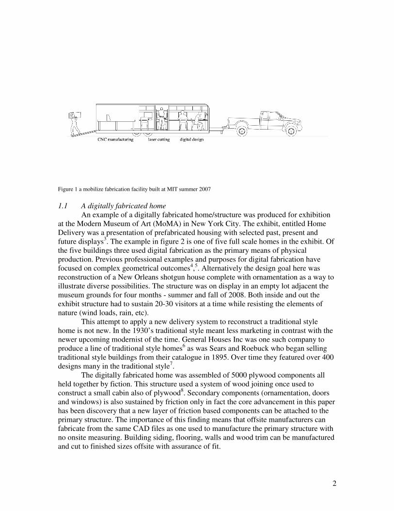
Finally, the structure was not waterproof the interior was allow to take on water
and drain. Exterior surfacing was left unfinished in order to demonstrate the projects
structural capacity and that the structure was manufactured completely of CNC cut
plywood components. In most cases each component was painted with two coats of
exterior grade latex paint. Exterior dimensions are 16’-4” wide by 38’-2” feet long and
20’ high in height.
Figure
2 a Digitally Fabricated House at MoMA and a photo from the exhibit opening
1.2 Community based architectural production
For centuries architects have produced floor plan drawings, elevations and now
3D models of designs for purchase by potential patrons and clients. The process of
purchasing drawings is simple and intended to keep the cost of production low however,
physical production can be complex. A modern day example of designs for sale extends
from the production of architectural pattern books. Mostly a product of the 20th
century
they are tools used to assist in the building of towns9. Within these well illustrated
documents are architectural designs and alternative solutions that define building types
and details.
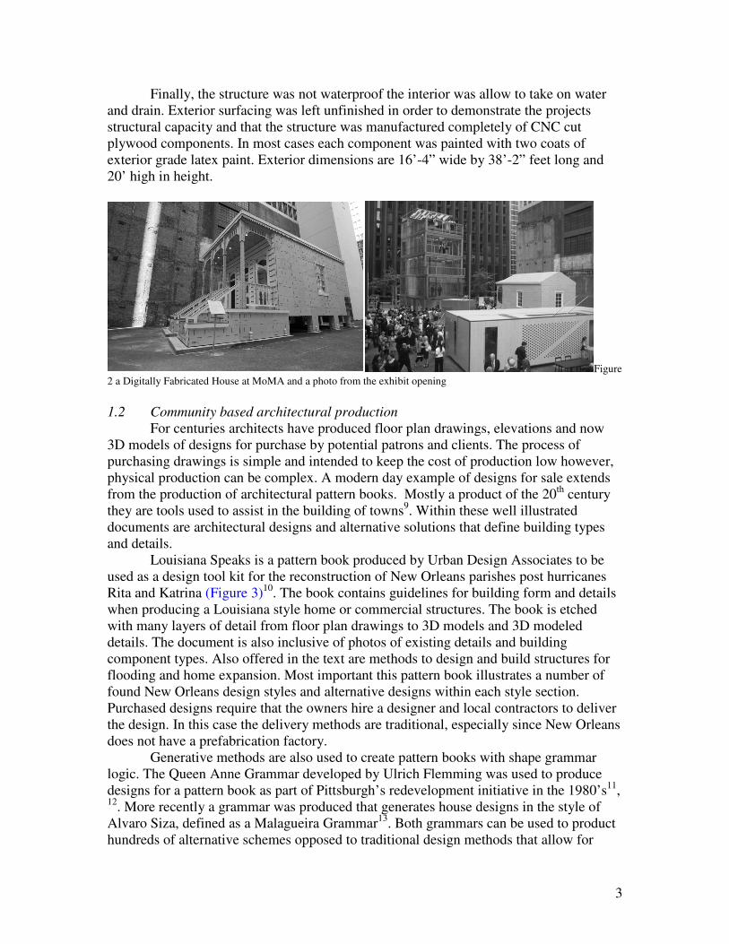
Louisiana Speaks is a pattern book produced by Urban Design Associates to be
used as a design tool kit for the reconstruction of New Orleans parishes post hurricanes
Rita and Katrina (Figure 3)10
. The book contains guidelines for building form and details
when producing a Louisiana style home or commercial structures. The book is etched
with many layers of detail from floor plan drawings to 3D models and 3D modeled
details. The document is also inclusive of photos of existing details and building
component types. Also offered in the text are methods to design and build structures for
flooding and home expansion. Most important this pattern book illustrates a number of
found New Orleans design styles and alternative designs within each style section.
Purchased designs require that the owners hire a designer and local contractors to deliver
the design. In this case the delivery methods are traditional, especially since New Orleans
does not have a prefabrication factory.
Generative methods are also used to create pattern books with shape grammar
logic. The Queen Anne Grammar developed by Ulrich Flemming was used to produce
designs for a pattern book as part of Pittsburgh’s redevelopment initiative in the 1980’s11
, 12
. More recently a grammar was produced that generates house designs in the style of
Alvaro Siza, defined as a Malagueira Grammar13
. Both grammars can be used to product
hundreds of alternative schemes opposed to traditional design methods that allow for
4
production of one scheme at a time. They also demonstrate that grammars can be used to
generate the initial 3D shape model. Unfortunately the end result for shape grammars are
design geometries the process requires construction documentation and a method of
physical production.
Figure 3 Examples of designs and alternative designs from the Louisiana Speaks pattern book
2. Prefabricated home delivery
Although prefabrication is almost a century old the process is relatively new..
Either from paper drawings or CAD a factory based approach to construction expects to
elevate production by working in enclosed spaces. Of the many early pioneers in
prefabrication the method was the message, the way the houses were delivered was as
much a part of the sale as the house. Independent builders such as John Manning, a
London based shipbuilder in 1830 and Sears Roebuck in 1908 published catalogues of
their houses14
. They both recognized the potential of small scale home delivery from
prefabricated components and that the catalogue approach was the message. Advanced
companies such as American Houses message was in advance steel framed houses
marketed as high quality and durability. Perhaps one of the most influential yet not so
successful prefabricated housing builders to date was Konrad Wachsmann and Walter
Gropius’General Panel Co. They produced the Packaged House for returning GIs from
World War II as a panelized product. Convenience in delivery was the message, their
vision was to convert factories around the country to build panels opposed to armaments.
The first was the Lockheed Factory in Burbank California equipped with expensive
machinery and an extensive production line that unfortunately only end up producing
doors and Hollywood stage sets.
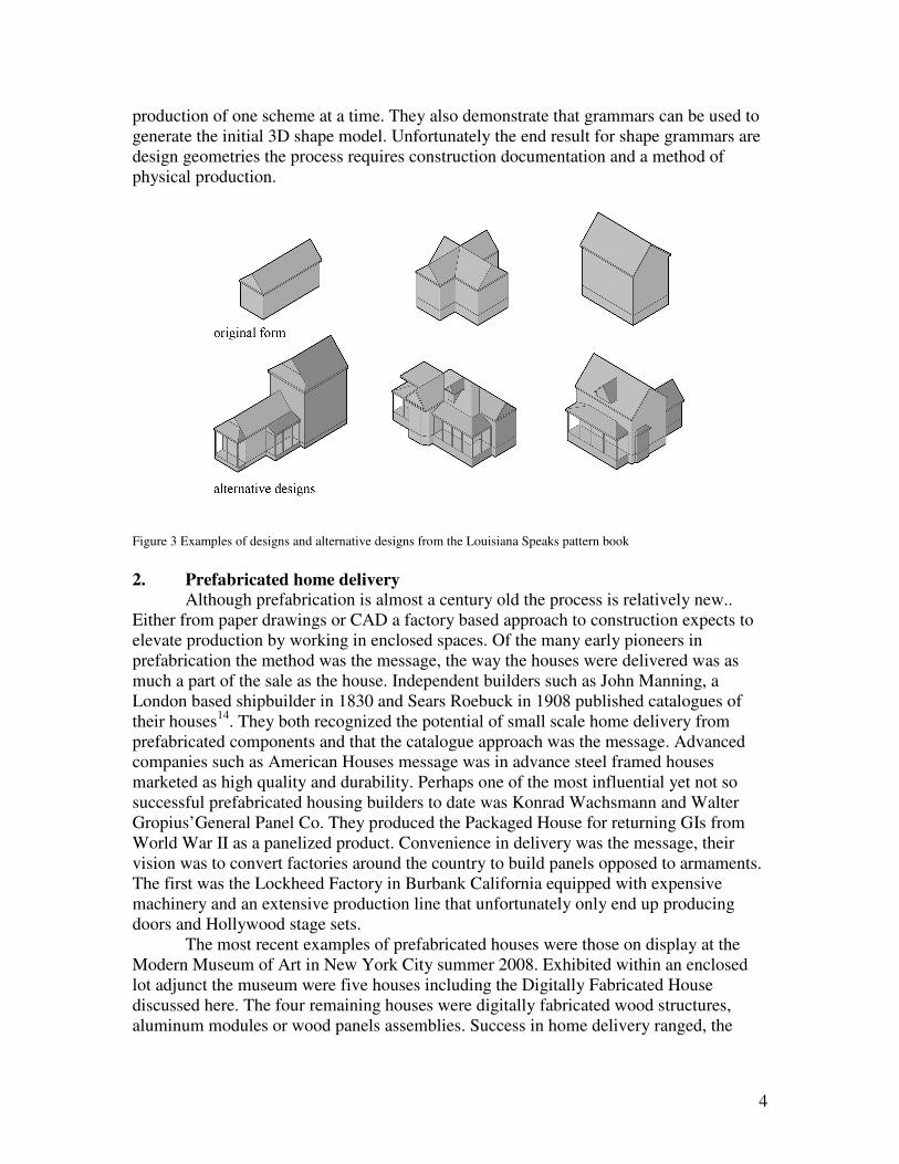
The most recent examples of prefabricated houses were those on display at the
Modern Museum of Art in New York City summer 2008. Exhibited within an enclosed
lot adjunct the museum were five houses including the Digitally Fabricated House
discussed here. The four remaining houses were digitally fabricated wood structures,
aluminum modules or wood panels assemblies. Success in home delivery ranged, the
5
most successful were the houses with the most machine cut parts and the houses with
assemblies factored into manufacturing.
The cellophane house took advantage of manufacturing control by generating a
Building information modeling. BIM is a representational tool used to track materials,
construction methods and documentation; it has yet to move into the realm of digital
fabrication. It also allows for generation of the buildings geometry, spatial relationships
between building components and material properties for all components. The software
was also used by Keiran Timberlake to model and guide manufacturing of the Loblobby
House in Maryland as well as the house on exhibit.
2.1 Legacy home production
Arts and craft in home building is a long tradition of production. It is seen as a
reaction to the industrial mechanized industry developed in the late 1800’s. It is a method
of production and a way of working in particular by hand and eye. Success in production
is based on the skill level of the individual, the quality and sometimes quantity of tools
and good materials. Both the factory built and onsite homes are a craft based system of
production where quality is relative to skill level and experience of each worker.
For carpenters mental calculation is a function of craft based construction where
mastery is governed by good calculations and relationships between parts. Skills also
range in ability to mentally calculate structure, arrangement of assemblies and potential
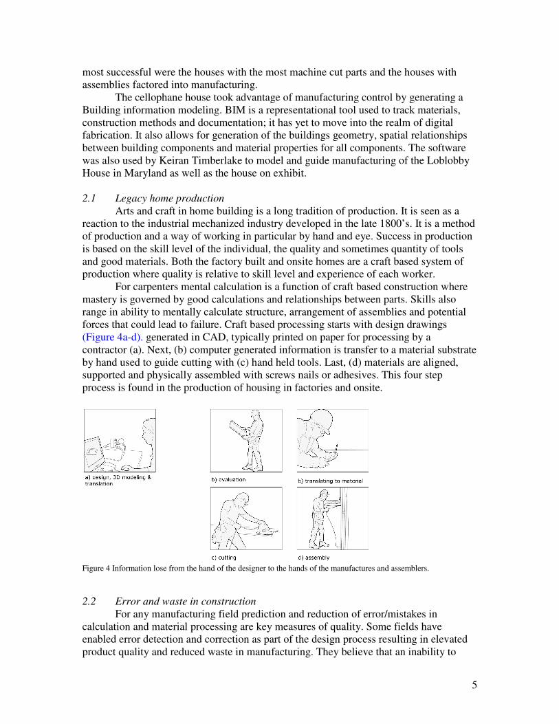
forces that could lead to failure. Craft based processing starts with design drawings
(Figure 4a-d). generated in CAD, typically printed on paper for processing by a
contractor (a). Next, (b) computer generated information is transfer to a material substrate
by hand used to guide cutting with (c) hand held tools. Last, (d) materials are aligned,
supported and physically assembled with screws nails or adhesives. This four step
process is found in the production of housing in factories and onsite.
Figure 4 Information lose from the hand of the designer to the hands of the manufactures and assemblers.
2.2 Error and waste in construction
For any manufacturing field prediction and reduction of error/mistakes in
calculation and material processing are key measures of quality. Some fields have
enabled error detection and correction as part of the design process resulting in elevated
product quality and reduced waste in manufacturing. They believe that an inability to
6
detect and correct error reduces the designer’s ability to propose more radical designs15
.
Automobile manufacturing is an integrated process of error detection and corrected
during design. The automotive industry has built in measures for energy consumption in
labor movement and how it contributes to error and waste. The more the worker has to
move or work with heavy tools the greater the opportunity for error. Toyota introduced a
plan to reduce waste through 14 manufacturing principles16
. Examples include lowering
the wait time between component assembly, reduction in storage and supply of material
in the factory, not overburdening people with heavy equipment. They are able to increase
quality by removing the burdens of labor that lead to errors in the final product.
For measure in this paper waste is defined as reconstruction or overlapping of
data creation by parties other than the original source-the designer – this reconstruction of
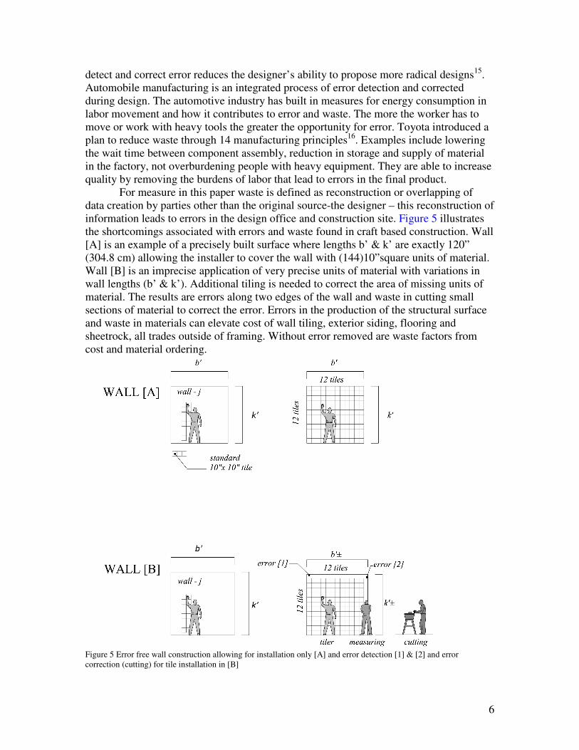
information leads to errors in the design office and construction site. Figure 5 illustrates
the shortcomings associated with errors and waste found in craft based construction. Wall
[A] is an example of a precisely built surface where lengths b’ & k’ are exactly 120”
(304.8 cm) allowing the installer to cover the wall with (144)10”square units of material.
Wall [B] is an imprecise application of very precise units of material with variations in
wall lengths (b’ & k’). Additional tiling is needed to correct the area of missing units of
material. The results are errors along two edges of the wall and waste in cutting small
sections of material to correct the error. Errors in the production of the structural surface
and waste in materials can elevate cost of wall tiling, exterior siding, flooring and
sheetrock, all trades outside of framing. Without error removed are waste factors from
cost and material ordering.
Figure 5 Error free wall construction allowing for installation only [A] and error detection [1] & [2] and error
correction (cutting) for tile installation in [B]
7
3. Materializing a design: key principles
The digital fabrication production process for the exhibit structure is called
materialization. It is a method of production that makes each step in a process from
design to physical assembly computable. There are five to six basic steps in the process
starting with design and ending with digitally guided assembly. A materialized artifact is
production starting from 3D model, the process and results are organized with the
following characteristics:
1- Initial shapes start as 3D models
2 – Computer functions are used to subdivide the initial shape into elements
3 – Each element is generated with attachment features that related to adjacent objects.
4 – 3D objects are manufacture in 2D with labels for hand assembly.
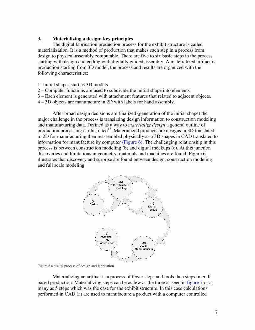
After broad design decisions are finalized (generation of the initial shape) the
major challenge in the process is translating design information to construction modeling
and manufacturing data. Defined as a way to materialize design a general outline of
production processing is illustrated17
. Materialized products are designs in 3D translated
to 2D for manufacturing then reassembled physically as a 3D shapes in CAD translated to
information for manufacture by computer (Figure 6). The challenging relationship in this
process is between construction modeling (b) and digital mockups (c). At this junction
discoveries and limitations in geometry, materials and machines are found. Figure 6
illustrates that discovery and surprise are found between design, construction modeling
and full scale modeling.
Figure 6 a digital process of design and fabrication
Materializing an artifact is a process of fewer steps and tools than steps in craft
based production. Materializing steps can be as few as the three as seen in figure 7 or as
many as 5 steps which was the case for the exhibit structure. In this case calculations
performed in CAD (a) are used to manufacture a product with a computer controlled
8
device (b) and assembled by hand (c) (figure 6). For models of greater size with more
steps the challenges associated with building a construction model are great. Construction
modeling requires generation of as hundreds of elements CAD. Complexity in CAD is
managed by early generation of a construction system defined by Mitchell predetermined
library of elements can serve as part of a functional grammar18
.
Figure 7 a materializing process use to build a physical model of a cube
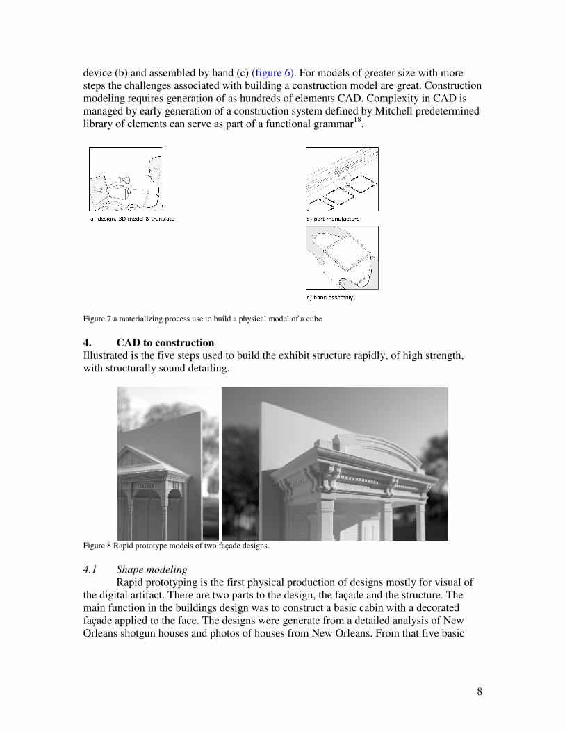
4. CAD to construction
Illustrated is the five steps used to build the exhibit structure rapidly, of high strength,
with structurally sound detailing.
Figure 8 Rapid prototype models of two façade designs.
4.1 Shape modeling
Rapid prototyping is the first physical production of designs mostly for visual of
the digital artifact. There are two parts to the design, the façade and the structure. The
main function in the buildings design was to construct a basic cabin with a decorated
façade applied to the face. The designs were generate from a detailed analysis of New
Orleans shotgun houses and photos of houses from New Orleans. From that five basic
9
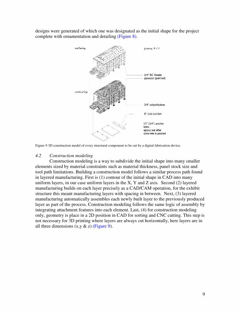
designs were generated of which one was designated as the initial shape for the project
complete with ornamentation and detailing (Figure 8).
Figure 9 3D construction model of every structural component to be cut by a digital fabrication device.
4.2 Construction modeling
Construction modeling is a way to subdivide the initial shape into many smaller
elements sized by material constraints such as material thickness, panel stock size and
tool path limitations. Building a construction model follows a similar process path found
in layered manufacturing. First is (1) contour of the initial shape in CAD into many
uniform layers, in our case uniform layers in the X, Y and Z axis. Second (2) layered
manufacturing builds on each layer precisely as a CAD/CAM operation, for the exhibit
structure this meant manufacturing layers with spacing in between. Next, (3) layered
manufacturing automatically assembles each newly built layer to the previously produced
layer as part of the process. Construction modeling follows the same logic of assembly by
integrating attachment features into each element. Last, (4) for construction modeling
only, geometry is place in a 2D position in CAD for sorting and CNC cutting. This step is
not necessary for 3D printing where layers are always cut horizontally, here layers are in
all three dimensions (x,y & z) (Figure 9).
10
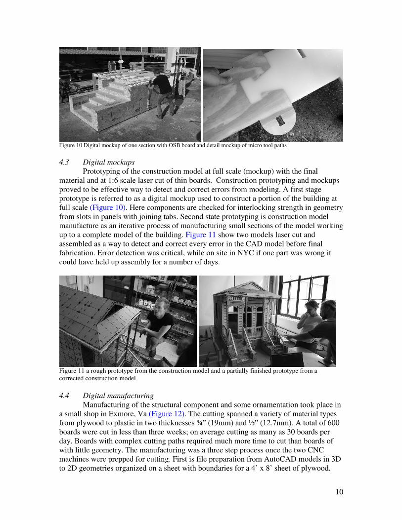
Figure 10 Digital mockup of one section with OSB board and detail mockup of micro tool paths
4.3 Digital mockups
Prototyping of the construction model at full scale (mockup) with the final
material and at 1:6 scale laser cut of thin boards. Construction prototyping and mockups
proved to be effective way to detect and correct errors from modeling. A first stage
prototype is referred to as a digital mockup used to construct a portion of the building at
full scale (Figure 10). Here components are checked for interlocking strength in geometry
from slots in panels with joining tabs. Second state prototyping is construction model
manufacture as an iterative process of manufacturing small sections of the model working
up to a complete model of the building. Figure 11 show two models laser cut and
assembled as a way to detect and correct every error in the CAD model before final
fabrication. Error detection was critical, while on site in NYC if one part was wrong it
could have held up assembly for a number of days.
Figure 11 a rough prototype from the construction model and a partially finished prototype from a
corrected construction model
4.4 Digital manufacturing
Manufacturing of the structural component and some ornamentation took place in
a small shop in Exmore, Va (Figure 12). The cutting spanned a variety of material types
from plywood to plastic in two thicknesses ¾” (19mm) and ½” (12.7mm). A total of 600
boards were cut in less than three weeks; on average cutting as many as 30 boards per
day. Boards with complex cutting paths required much more time to cut than boards of
with little geometry. The manufacturing was a three step process once the two CNC
machines were prepped for cutting. First is file preparation from AutoCAD models in 3D
to 2D geometries organized on a sheet with boundaries for a 4’ x 8’ sheet of plywood.
11
These files were prepared for prototyping during the construction modeling phase. The
2D files were then altered for CNC cutting by including micro paths or short tool paths
that rounded sharp edges and remove extra material for inside corners. The components
were transported with the skeleton that they were cut from for complete flat pack
transportation.
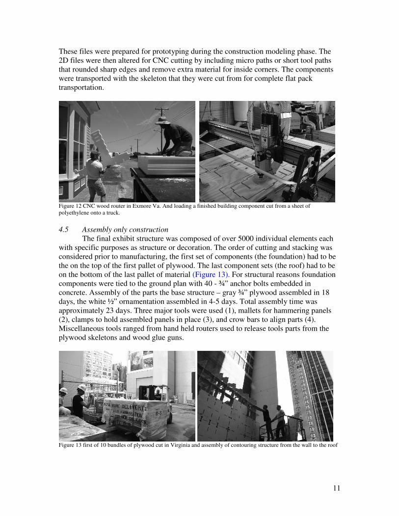
Figure 12 CNC wood router in Exmore Va. And loading a finished building component cut from a sheet of
polyethylene onto a truck.
4.5 Assembly only construction
The final exhibit structure was composed of over 5000 individual elements each
with specific purposes as structure or decoration. The order of cutting and stacking was
considered prior to manufacturing, the first set of components (the foundation) had to be
the on the top of the first pallet of plywood. The last component sets (the roof) had to be
on the bottom of the last pallet of material (Figure 13). For structural reasons foundation
components were tied to the ground plan with 40 - ¾” anchor bolts embedded in
concrete. Assembly of the parts the base structure – gray ¾” plywood assembled in 18
days, the white ½” ornamentation assembled in 4-5 days. Total assembly time was
approximately 23 days. Three major tools were used (1), mallets for hammering panels
(2), clamps to hold assembled panels in place (3), and crow bars to align parts (4).
Miscellaneous tools ranged from hand held routers used to release tools parts from the
plywood skeletons and wood glue guns.
Figure 13 first of 10 bundles of plywood cut in Virginia and assembly of contouring structure from the wall to the roof
12
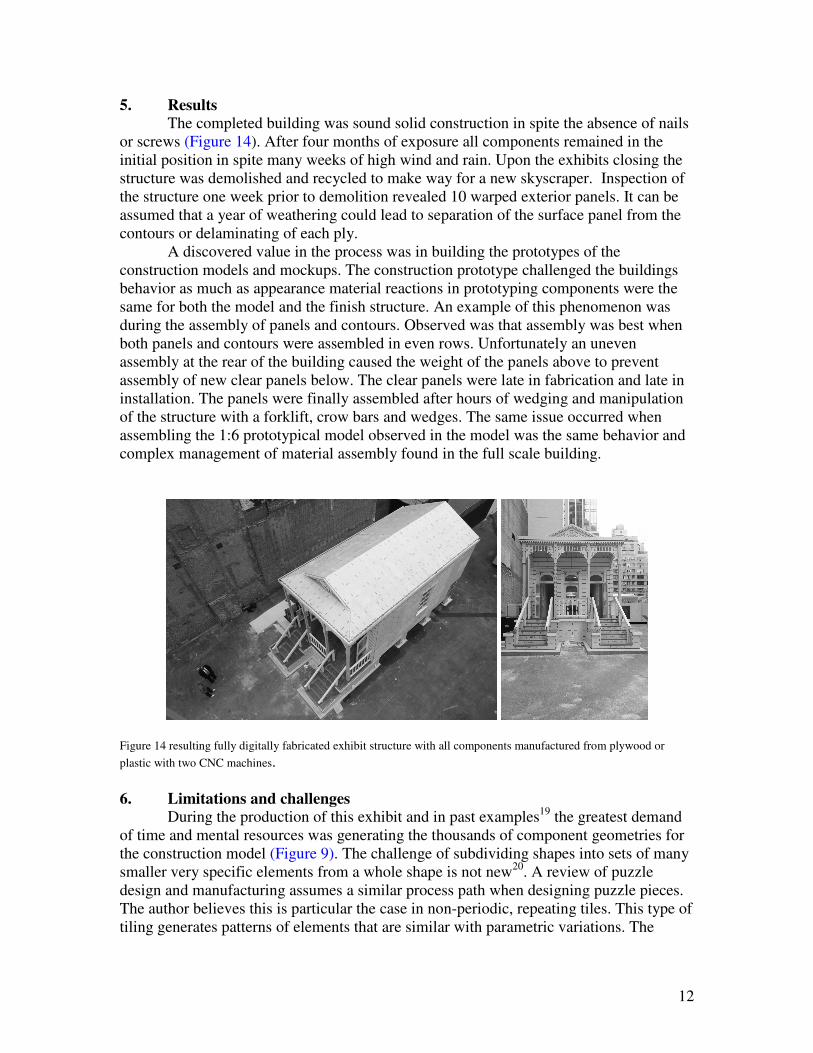
5. Results
The completed building was sound solid construction in spite the absence of nails
or screws (Figure 14). After four months of exposure all components remained in the
initial position in spite many weeks of high wind and rain. Upon the exhibits closing the
structure was demolished and recycled to make way for a new skyscraper. Inspection of
the structure one week prior to demolition revealed 10 warped exterior panels. It can be
assumed that a year of weathering could lead to separation of the surface panel from the
contours or delaminating of each ply.
A discovered value in the process was in building the prototypes of the
construction models and mockups. The construction prototype challenged the buildings
behavior as much as appearance material reactions in prototyping components were the
same for both the model and the finish structure. An example of this phenomenon was
during the assembly of panels and contours. Observed was that assembly was best when
both panels and contours were assembled in even rows. Unfortunately an uneven
assembly at the rear of the building caused the weight of the panels above to prevent
assembly of new clear panels below. The clear panels were late in fabrication and late in
installation. The panels were finally assembled after hours of wedging and manipulation
of the structure with a forklift, crow bars and wedges. The same issue occurred when
assembling the 1:6 prototypical model observed in the model was the same behavior and
complex management of material assembly found in the full scale building.
Figure 14 resulting fully digitally fabricated exhibit structure with all components manufactured from plywood or
plastic with two CNC machines.
6. Limitations and challenges
During the production of this exhibit and in past examples19
the greatest demand
of time and mental resources was generating the thousands of component geometries for
the construction model (Figure 9). The challenge of subdividing shapes into sets of many
smaller very specific elements from a whole shape is not new20
. A review of puzzle
design and manufacturing assumes a similar process path when designing puzzle pieces.
The author believes this is particular the case in non-periodic, repeating tiles. This type of
tiling generates patterns of elements that are similar with parametric variations. The
13
article claims that prefabricated building parts are also non-periodic in nature and repeat
in sets as parametric objects.
This was not the case for the exhibit structure, discovered were geometries that
had a puzzle like pattern but varied in geometries for connections between parts. For the
structure an initial library of geometries was repeated, the actual final geometry cut for
construction was periodic, seldom did parts repeat. For example, the finished contours in
the structure varied in relationship and length in order to increase the strength of the
complete structure (Figure 8). Wind loads, human loads and weather required the
structure to be fabricated of interlocking geometries. This means that the structural
pattern be assured to be non-repeating internal contouring was a weave of plywood
components.
Last, our greatest difficulty when modeling was that when challenged physically
though prototyping elements in the model had to emerge into elements outside the
framework of the original library of parts. Emergence can be described as some process
the software designer did not intentionally code into the algorithm21
. It can be seen as a
variable outside of the boundary of the grammar requiring the computer to invent or
emerge an option anew. Subdividing from the starting shapes is based on many factors
such as material thickness, sizes in the x and y directions and places to connect parts to
other parts. It may be possible to predict some aspects of the subdivision in order to build
and reuse a parametric component. However in the case of the exhibit structure the
emergence of so many new variations of the initial element lead to a switch in software
from parameterized software to solid modeling. Shape grammars claim to solve this
problem however a shape grammar interpreter is needed to make production possible22
.
7. Concluding remarks
This report presents a process of home delivery with digital fabrication machinery
as an alternative to craft and factory based prefabrication. It demonstrated that
community based home delivery is possible with computer controlled machines. A
materializing process was also substantiated with a case study demonstrating that an
interlock system of plywood parts is possible for rapid, highly precise construction.
Alternatively fasteners such as metal screws, nails and liquid adhesives are suggested for
real structures, however the concept of friction as a primary attachment method only adds
to the strength of any structure.
Future studies will require more systems than a structural demonstration to
models inclusive of plumbing, electrical and mechanical systems. Possible is precut
flooring from the factory with edges and opening precut from a CAD file. Also possible
is cutting of exterior siding, interior boards and ceilings for onsite assembly only. Also
needed is a model of community based manufacturing illustrating the possibilities of
hiring local labor to manufacture buildings with machines. Possible is the creation of new
localize economies and assured integration of trades that interface with new building
construction.
Acknowledgements
Rockefeller Foundation, the primary sponsor, American Institute of Architects, Boise
Cascade and Shopbot Tools
14
Reference citation
1 Pine, J., (2004) Mass Customization: The new frontier in business competition, Harvard Business School
Press
2 Kieran, S., Timberlake, J., (2004) refabricating Architecture, McGraw Hill Co.
3 Bergdoll, B., Christensen, P., (2008), Home Delivery, Fabricating the Modern Dwelling, Museum of
Modern Art, New York,
4 Kolarevic, B., (2003), Architecture in the Digital Age, Design and Manufacturing, Spoon Press
5 Schodek, D., Bechthold, M., Griggs, K., Kao, K., Steinberg, M., (2007) Digital Design and
Manufacturing: CAD/CAM Applications in Architecure and Design, Jon Wiley & Son
6 Davies, C. (2005), The Prefabricated Home, Reaktion Books
7 (1990) Sears, Roebuck Home Builders Catalogue, The complete illustrated 1910 Edition,
8 Sass L., (2005) A wood frame grammar: a generative system for digital fabrication, International Journal
of Architectural Computing, Issue 01, Number 04, pp 51-67
9 Grindroz, R., Robinson, R., (2004) The Architectural Pattern Book, Urban Design Associates, W.W.
Norton & Company
10 Urban Design Associates, (2006) Louisiana Speaks: A pattern book, Louisiana Recovery Authority,
11 Flemming, U., (1987) More than the sum of parts: the grammar of Queen Anne houses, Environment
and Planning B 1987 14 323 – 350
12 Flemming, U., with Gindroz, Coyne, R., Pithavadian, S. (1986) A Pattern Book for Shadyside, A ppern
Book for Shadyside, Technical report, Department of Architecture, Carnegie-Mellon University, Pittsburg,
PA.
13 Duarte. J., (2005) Towards the mass customization of housing: the grammar of Siza's houses at
Malagueira, Environment and Planning B, Vol. 32, Iss. 3 pp32 347 – 380
14 Davies, C. (2005), The Prefabricated Home, Reaktion Books, pp. 44-68
15 Goh, Y., McMahon, C., Booker, J., (2005) Development and characterization of error functions in
design, Research Engineering Design, Vol. 18, pp. 129-148
16 Liker, J. K., (2004) The Toyota Way : 14 management principles from the world’s greatest
manufacturer, McGrawhill.
17 Sass, L., Oxman, R., (2005),
11 Mitchell, W., (1991) Functional Grammar: An Introduction, in Reality and Virtual Reality, ed. Glenn
Goldman and Michael Zdepski, Association for Computer Aided Design in Architecture.
19 Sass, L., (2006) Synthesis of design production with integrated digital fabrication, Automation in
Construction, Vol. 16, No.03, pp. 298-310
20 Lenart, M., (1993) Construction problems as tiling puzzles, Design Studies, Vol. 10, Iss. 1 pp. 40-52

15
21 Symons, J., (2008) Computational models of emergent properties, Minds and Machines Vol. 18, pp.
475-491
22 Knight, T., (2003 )Computing with emergence, Environment and Planning B, Vol. 30, pp. 125-155