a distributed coordination framework for wireless sensor and actor
TRANSCRIPT
A Distributed Coordination Framework for Wireless Sensorand Actor Networks
Tommaso Melodia, Dario Pompili, Vehbi C. Gungor and Ian F. AkyildizBroadband and Wireless Networking Laboratory
School of Electrical & Computer EngineeringGeorgia Institute of Technology, Atlanta, GA 30332
{tommaso, dario, gungor, ian}@ece.gatech.edu
ABSTRACTWireless Sensor and Actor Networks (WSANs) are composed ofa large number of heterogeneous nodes calledsensorsandactors.The collaborative operation of sensors enables thedistributed sens-ing of a physical phenomenon, while the role of actors is to collectand process sensor data and perform appropriate actions.
In this paper, a coordination framework for WSANs is addressed.A new sensor-actor coordination model is proposed, based onanevent-driven clusteringparadigm in which cluster formation is trig-gered by an event so that clusters are created on-the-fly to opti-mally react to the event itself and provide the required reliabilitywith minimum energy expenditure. The optimal solution is deter-mined by mathematical programming and a distributed solution isalso proposed. In addition, a new model for actor-actor coordina-tion is introduced for a class of coordination problems in which thearea to be acted upon is optimally split among different actors. Anauction-based distributed solution of the problem is also presented.
Performance evaluation shows how global network objectives,such as compliance with real-time constraints and minimum en-ergy consumption, can be reached in the proposed framework withsimple interactions between sensors and actors that are suitable forlarge-scale networks of energy-constrained devices.
Categories and Subject Descriptors:C.2.2 [Computer-Communication Networks]: Network Protocols-routing protocols
General Terms: Algorithms, Design, Reliability, Performance.
Keywords: Wireless Sensor and Actor Networks, Real-Time Com-munications, Energy Efficiency.
1. INTRODUCTIONWireless Sensor and Actor Networks (WSANs) [1] are com-
posed of a large number of heterogeneous nodes calledsensorsandactors. Sensors are low-cost, low-power, multi-functional devicesthat communicate untethered in short distances. The role ofac-tors is to collect and process sensor data and perform appropriateactions. Hence, actors are resource-rich nodes equipped with bet-
Permission to make digital or hard copies of all or part of this work forpersonal or classroom use is granted without fee provided that copies arenot made or distributed for profit or commercial advantage and that copiesbear this notice and the full citation on the first page. To copy otherwise, torepublish, to post on servers or to redistribute to lists, requires prior specificpermission and/or a fee.MobiHoc’05,May 25–27, 2005, Urbana-Champaign, Illinois, USA.Copyright 2005 ACM 1-59593-004-3/05/0005 ...$5.00.
ter processing capabilities, higher transmission powers,and longerbattery life.
In WSANs, a large number of sensor nodes, i.e., on the order ofhundreds or thousands, are randomly deployed in a target area toperform a collaborative sensing task. Such a dense deployment isusually not necessary for actor nodes, since actors are sophisticateddevices with higher capabilities that can act on large areas.
The collaborative operation of the sensor nodes enables thedis-tributed sensingof a physical phenomenon. After sensors detect anevent occurring in the environment, the event data is distributivelyprocessed and transmitted to the actors, which gather, process, andeventually reconstruct the event data. We refer to the process ofestablishing data paths between sensors and actors assensor-actorcoordination. Once an event has been detected, the actors coordi-nate with each other to make a decision on the most appropriateway to perform the action. We refer to this process asactor-actorcoordination. As a result, the operation of a WSAN can be thoughtof to be an event-sensing, decision, and acting loop.
WSANs can be an integral part of systems such as battlefieldsurveillance, nuclear, biological or chemical attack detection, homeautomation and environmental monitoring [1]. For example,in firedetection applications, sensors can relay the exact originand inten-sity of the fire to water sprinkler actors so that the fire can easily beextinguished before it spreads. Similarly, motion and light sensorsin a building can detect the presence of intruders, and commandcameras or other instrumentations to track them. Furthermore, sen-sors for structural health monitoring in airplanes or spaceships candrive instruments to timely take countermeasures against criticalmechanical stress or structural faults. As a last example, in earth-quake scenarios sensors can help locate survivors and guiderobotsperforming rescue operations.
In a way, WSANs can be considered a distributed control systemthat needs to timely react to sensor information with an effectiveaction. For this reason,real-time coordination and communicationin WSANs is an important concern so as to guarantee timely exe-cution of the right actions. Some recent papers [2][3][4] have con-sidered the issue of real-time communication in sensor networks.However, as discussed in [5], there are still many open researchchallenges in order to enable real-time communication and coordi-nation in sensor networks, especially due to resource constraintsand scalability issues. Besides, none of these works deals withsensor-actor coordination. Theenergy efficiencyof network com-munications is also crucial, since sensors are resource-constrainednodes with limited battery lifetime and communication capabilities[6]. Furthermore, sensor network protocols and algorithmsshouldbescalableandlocalized, as the number of nodes can be arbitrarilyhigh.
It has been recently shown in the literature that a fundamen-

tal trade-off exists between energy and latency for data deliveryin sensor networks [7]. For this reason, in WSANs it is requiredto deliver event data in an energy-efficient way while respectingreal-time delay constraints. As far as scalability is concerned, ithas been pointed out [8][9] that the routing protocols that do notuse geographical location information do not scale well in largenetworks. Conversely, the recent availability of small, inexpen-sive, and low-power GPS (Global Positioning System) receivers,together with techniques to deduce relative sensor coordinates fromsignal strengths [10], paved the way forGeographical Routing(alsoPosition Based Routing) algorithms [11], which are becoming themost promising scalable solutions for critically energy-constrainedsensor networks. Therefore, in this paper we study thesensor-actorcoordinationbased on a geographical routing paradigm.
In order to guarantee scalability and energy efficiency, severalsolutions based on dividing the sensor network into different clus-ters have been proposed [12][13][14][15]. Most of the existingclustering algorithms can be classified astopology dependent, i.e.,clusters are predetermined, depend on the topology of the sensornetwork, and may be adaptively reconfigured to deal with mobil-ity or failure of the sensor nodes. Usually, in topology-dependentclustering one of the sensors is elected as acluster-headin eachcluster. When an event occurs, each sensor is already associatedwith a cluster-head.
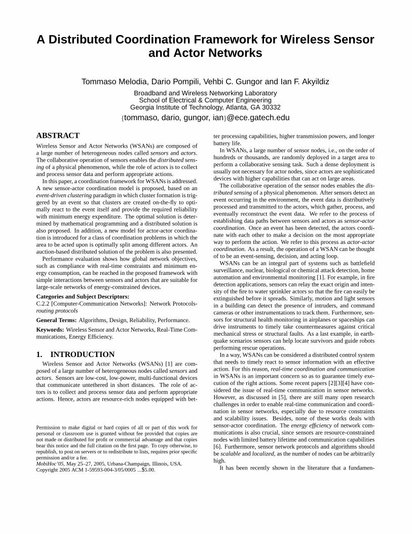
In this paper, we propose to base the sensor-actor coordinationon a newevent-driven clusteringparadigm, where cluster forma-tion is triggered by an event so that clusters are createdon-the-flytooptimally react to the event. In our approach, sensors detecting anevent coordinate with each other so as to optimally associate eachsensor with an actor. This way, only the event area is clustered, andeach cluster consists of those sensor nodes that send their data to thesame actor. Hence, the event information is collected at theopti-mal actor nodes while existing energy resources are better utilized,since clusters are formed only when necessary, based on the eventfeatures and on the position of the actors. The resulting architectureis shown in Fig. 1. The event-driven clustering approach also elim-inates the communication overhead to maintain clusters before theevent occurs, which is desirable especially in applicationscenarioswhere events are rare.
In addition, we introduce a model for actor-actor coordination.We define an optimization model for a class of coordination prob-lems in which the area to be acted upon is optimally split amongdifferent actors depending on the actor capabilities.
The overall contribution of this paper is a comprehensive frame-work for coordination problems in WSANs, and can be outlinedas:
Sensor-actor coordination:- We define the event-driven clustering problem and determine theoptimal solution byInteger Linear Programming (ILP)[16].- We propose a multi-state distributed algorithm that achieves anenergy-efficient solution for sensor-actor coordination and includesan adaptive mechanism that trades-off energy consumption for de-lay when event data must be delivered to the actors within pre-determined latency bounds.Actor-actor coordination:- We define an optimization problem to divide the action work-load among different actors, depending on the characteristics of theevent, and formulate it as aMixed Integer Non-Linear Program(MINLP) [17].- We propose a distributed algorithm for the actor-actor coordina-tion problem, based on localized auctions among the actors.
To the best of our knowledge, this is the first paper to compre-hensively deal with integrated networks of sensors and actors, andto propose a unified framework for communication and coordina-
��������
��������
��������
��������
��������
��������
��������
��������
��������
��������
��������
��������
: sensor
: actor/collector
: actor
Event area
Figure 1: Event-driven clustering with multiple actors.
tion problems in WSANs. Since WSANs can enable a broad rangeof applications with different requirements, we focus on scenarioswith immobile actors that can act on a limited area defined by theiraction range. The ultimate objective of this work is to demonstratehow global network objectives, such as compliance with real-timeconstraints and minimum energy consumption, can be reachedinthe proposed framework with simple interactions between sensorsand actors, suitable for large-scale networks of energy-constraineddevices.
The remainder of this paper is organized as follows. In Sections2 and 3 we discuss the sensor-actor coordination problem. Inpar-ticular, in Section 2 we state the sensor-actor coordination problemand propose an integer linear programming formulation, while inSection 3 we describe a distributed protocol for online solution ofthe problem. In Sections 4 and 5 we discuss the actor-actor coordi-nation problem. In particular, in Section 4 we state the actor-actorcoordination problem, while in Section 5 we introduce a distributedsolution based on a real-time localized auction mechanism.De-tailed comparative performance evaluation and simulationresultsare presented in Section 6. Finally, in Section 7 we draw the mainconclusions.
2. SENSOR-ACTOR COORDINATION:PROBLEM FORMULATION
Since, as discussed in the previous section, sensor-actor commu-nications may have real-time requirements, we introduce a novelnotion of reliability that accounts for the percentage of total re-ceived packets that are received within a pre-defined latency bound(which we refer to asreliable packets). Unlike other notions ofreliability, the definition introduced here is related to the real-timedelivery of data packets from sources to actors.
DEFINITION 1. Thelatency boundB is the maximum allowedtime between the instant when the physical features of the event aresampled by the sensors and the instant when the actor receives adata packet describing these event features. A data packet that doesnot meet the latency boundB when it is received by an actor is saidto beexpiredand thusunreliable. Similarly, a data packet receivedwithin the latency bound is said to beunexpiredand thusreliable.
DEFINITION 2. Theevent reliabilityr is the ratio of reliabledata packets over all the packets received in a decision interval 1.Theevent reliability thresholdrth is the minimumevent reliability1Whenever a packet is dropped by an intermediate sensor, eitherbecause it violates the latency bound constraint or becauseof net-
2

required by the application. Thelack of reliability is the difference(rth − r) between the required event reliability thresholdrth andthe observed event reliabilityr at a given time. A negative lack ofreliability indicates a reliability above the required threshold andis also referred to as anexcess of reliability.
Note that the latency boundB and the event reliability thresholdrth are dependent on the application requirements.
The sensor-actor coordination problem consists of establishingdata paths from each sensor residing in the event area to the ac-tors by i) ensuring that the observed reliabilityr is above the eventreliability thresholdrth (i.e., r ≥ rth); ii) minimizing the energyconsumption associated with data delivery paths.
We refer to our solution for the sensor-actor coordination prob-lem asevent-driven clustering with multiple actorsand model it asan Integer Linear Program (ILP). In Sections 2.1 and 2.2 we de-scribe the network and energy model, respectively. In Section 2.3we provide the complete ILP formulation of the problem.
2.1 Network ModelThe network of sensor and actor nodes is represented as a graph
G(SV , SE), whereSV = {v1, v2, . . . , vN} is a finite set of nodes(vertexes) in a finite-dimension terrain, withN = |SV |, andSE isthe set of links (edges) among nodes, i.e.,eij ∈ SE iff nodesvi
andvj (alsoi andj for simplicity in the following) are within eachother’s transmission range. LetSA represent the set of actors, withNA = |SA|. We refer to an actor that is collecting traffic from oneor more sources as acollector. LetSS be the set of traffic sources,with NS = |SS |. This set represents the sensor nodes that detectthe event, i.e., the sensors that reside in the event area. Since the setof sources is disjoint from the set of actors,SA ⊂ SV , SS ⊂ SV ,andSA ∩ SS = ∅.
2.2 Energy ModelAn accurate model for energy consumption per bit at the physi-
cal layer isE = Etranselec + βdα + Erec
elec, whereEtranselec is a dis-
tance independentterm that takes into account overheads of trans-mitter electronics (PLLs, VCOs, bias currents, etc.) and digitalprocessing;Erec
elec is a distance independent term that takes intoaccount the overhead of receiver electronics, whileβdα accountsfor the radiated power necessary to transmit one bit over a dis-tanced between source and destination. As in [12], we assumethatEtrans
elec = Erecelec = Eelec. Thus, the overall expression sim-
plifies toE = 2Eelec + βdα, whereα is the exponent of the pathloss (2 ≤ α ≤ 5), β is a constant[Joule/(bits ·mα)], andEelec isthe energy needed by the transceiver circuitry to transmit or receiveone bit[Joule/bits].
In our energy model we consider that, when a sensor node re-ceives data from at least two other nodes, it aggregates the receivedinformation bydata fusion[18], i.e., a single packet is created bymerging multiple incoming packets, thus reducing the amount ofdata to be tranmsitted. To effectively support this function, an algo-rithm for data fusion should be implemented on each sensor, whichis out of the scope of this paper. Moreover, we ignore the process-ing cost in our model, since the processing cost is much lowerthanthe communication cost. This is justified by experimental resultson sensor network prototypes such as [19], where the energy nec-essary to transmit 1 kbit is shown to be equivalent to the energynecessary to execute 300,000 processor instructions.
work or channel impairments, a short notification packet is sent tothe actor, so that the lost packet can be taken into account inthecomputation of the reliability. Hence, in the definition “receivedpackets” refers to the sum of data and notification packets
2.3 Integer Linear ProgramThe objective of the optimization problem is to finddata aggre-
gation trees(da-trees) from all the sensors that reside in the eventarea (referred to as sources) to the appropriate actors. A da-treeis composed by aggregating individualflows, where a flow is de-fined as a connection between a sensor and an actor. All leavesin ada-tree are sources (but not all sources are necessarily leaves), andeach actor is either the root of a da-tree or does not participate inthe communication. Da-trees are constructed in such a way thateach source belongs to one tree only and each tree has only oneactor as its root. Therefore, each source is associated withan actorto achieve an optimal strategy for event-driven clustering.
In fact, event-driven clustering can be seen as a joint twofoldproblem: i) select the optimal subset of actors to which sensor read-ings will be transmitted; ii) construct the minimum energy da-treestowards those selected actors that meet the required event reliabilityconstraint. Each tree implicitly defines a cluster, which isconsti-tuted by all source nodes in the tree. Figure 1 gives an example ofthis configuration.
The optimal strategy for event-driven clustering is formulated asan Integer Linear Program(ILP) [16]. The network topology isassumed to be1-connected, i.e., at least one path exists betweeneach sensor and actor. Note that this is not a strict requirement indense sensor networks. We introduce the following notations thatare used in the problem formulation:- eij is a binary variable representing a link, that equals 1 iff nodesi andj are within each other’s transmission range;- cij is the cost of the link between nodesi andj, i.e.,2Eelec+βdα
ij ,wheredij represents the distance between nodesi andj;- xk
ij is a binary variable that equals 1 iff link(i, j) is part of theda-tree associated with actork;- fk,s
ij is a binary variable that equals 1 iff nodes sends data to actork and link(i, j) is in the path from sources to actork;- lk,s is a binary variable that equals 1 iff sensors sends data toactork;- pij is the propagation delay associated with link(i, j), defined asdij/v, wherev is the signal propagation speed;- d is a parameter that accounts for the average sum ofprocessing,queuing, andaccessdelay at each sensor node;- B is the latency bound on each source-actor flow;- r andrth are the event reliability and the required event reliabilitythreshold, respectively;- bk,s is a binary variable that equals 1 iff the connection betweensources and actork is not compliant with the latency bound, i.e.,the end-to-end delay is higher than the latency boundB;- Q is the number of non-compliant sources.
The problem can be cast as follows:
PComMin : Event-Driven Clustering with Multiple Actors
Given : eij , cij , pij , v, d, B, rth (1)
Find : xkij , fk,s
ij , lk,s, bk,s, r (2)
Minimize : CTOT =P
k∈SA
P(i,j)∈SE xk
ij · cij + γ · Q (3)
Subject to :Xj∈SV
(fk,ssj − fk,s
js ) = lk,s,∀s ∈ SS, ∀k ∈ SA; (4)Xj∈SV
(fk,skj − fk,s
jk ) = −lk,s,∀s ∈ SS,∀k ∈ SA; (5)Xj∈SV
(fk,sij − fk,s
ji ) = 0,
3

∀s ∈ SS ,∀k ∈ SA,∀i ∈ SV s.t. i 6= s, i 6= k; (6)
fk,sij ≤ eij ,∀s ∈ SS ,∀k ∈ SA,∀i ∈ SV ,∀j ∈ SV ; (7)
fk,sij ≤ xk
ij ,∀s ∈ SS ,∀k ∈ SA,∀i ∈ SV ,∀j ∈ SV ; (8)Xk∈SA
lk,s = 1, ∀s ∈ SS ; (9)
fk,sij ≤ lk,s, ∀s ∈ SS ,∀k ∈ SA,∀i ∈ SV ,∀j ∈ SV ; (10)
ε · [B−X
(i,j)∈SE
fk,sij (pij + d)] ≤ bk,s, ∀s ∈ SS,∀k ∈ SA; (11)
Q =X
k∈SA
Xs∈SS
bk,s; r =|SS | − Q
|SS |≥ rth. (12)
The objective function in (3) minimizes the overall energy con-sumption and imposes a penalty by multiplying the numberQ ofnon-compliant sources by a penalty coefficientγ whose value mustbe high enough (e.g., orders of magnitude higher than the energyconsumption) to guarantee uniqueness of the solution. Thisallowsminimizing the number of non-compliant sourcesQ (eq. 12) witha single-objective problem. As previously discussed, a flowis aconnection between a source and an actor. Flows associated withthe same actor are aggregated in a da-tree. Constraints (4),(5), and(6) express conservation of flows [16], i.e., each source generatesa flow, which is collected by an actor. In particular, constraint (4)guarantees that a source node generates a flow on the tree of theselected actor, and only on that one; while non-source nodesdo notgenerate any flow. Constraint (5) requires that flows generated byeach source be collected by one actor only. Constraint (6) imposesthat the balance between incoming and outgoing flows is null fornon-source and non-actor nodes. Constraint (7) ensures that flowsare created on links between adjacent nodes (i.e., that are withintransmission range of each other). Constraint (8) forces all flowsfrom different sources but directed towards the same actor to beaggregated in the tree associated with that actor. Constraint (9) im-poses that each source send data to exactly one actor. Constraint(10) ensures that all flow variables from a source to a particular ac-tor are zero unless that actor is selected by the source. Constraint(11) requires that the binary variablebk,s be equal to 1 always andonly when the flow between sources and actork violates the la-tency boundB. Note that the small negative coefficientε is neededto scale the value of the difference between the delay and thedelaybound to make it smaller than 1. In (12),Q is defined as the numberof non-compliant sources and the reliabilityr is constrained to beover the required threshold.
It can be shown that the problemPComMin is at least as complex
as the Geometric Connected Dominating Set problem, which isproven to be NP-complete [20]. Hence,P
ComMin is NP-complete.
However, it is still possible to solvePComMin for networks of moder-
ate size (up to 100 nodes), as will be shown in Section 6. This al-lows gaining some insight on the properties of the optimal solution,and using it as a benchmark for the performance of suboptimal, butmore scalable algorithms, such as that introduced in the followingsection.
3. SENSOR-ACTOR COORDINATION:DISTRIBUTED PROTOCOL
In this section, we introduce a scalable and distributed proto-col to addresses the sensor-actor coordination problem in WSANs.
The objective of the protocol is to build energy-efficient da-treesbetween the sources that reside in the event area and the actors, inorder to provide the required reliabilityrth with minimum energyexpenditure. The proposed protocol constructs da-trees betweensources and actors that can be seen as an approximate solution forthe event-driven clustering with multiple actors problem,describedin Section 2.
As discussed in [21], in geographical routing algorithmslocal-ized routing decisions, i.e., based on localized topology informa-tion, can lead to data paths whose energy efficiency is close tothe global optimum. This means that in densely deployed sensornetworks topology information related to network regions that are“far” from where the routing decision is being taken are not es-sential. In fact, this information does not considerably influencethe energy efficiency of the overall data path. For this reason, theobjective of the proposed protocol is to minimize the energycon-sumption by relying on localized information and ongreedyrout-ing decisions. Conversely, complying with pre-determineddelaybounds requires some form of end-to-end feedback. Hence, theproposed protocol favors local behavior for each individual sen-sor node that results in a global network behavior that is compliantwith the application requirements, i.e., provide an event reliabil-ity r above the required thresholdrth (defined in Section 2) andminimize the energy consumption. This is achieved by relying onfeedback information from the actors/collectors.
In the description of the protocol, we assume that each sensornode is aware of: i) its position, as the sensor node can be equippedwith a GPS receiver or the position can be determined by meansof localization techniques [10]; ii) the position of its neighbors, asevery node periodically sends its position to its neighbors; iii) theposition of the actors, as each actor periodically beacons its positionin the sensor field; iv) the network is synchronized by means ofone of the existing synchronization protocols [22]. A studyon theimpact of localization and synchronization errors is left for futurework.
An important issue in geographical routing algorithms is toavoidthe creation of loops in the data paths. Hence, before proceedingwith an overview of the proposed protocol, we introduce somecon-cepts related topath loop freedomthat will be used in the descrip-tion of the sensor-actor coordination framework.
DEFINITION 3. Given nodesv andx, theabsolute advanceofnodex, with respect tov, is the distance betweenv and its closestactor cv minus the distance betweenx and its closest actorcx
2.
DEFINITION 4. Given nodesv andx, theadvance towards thecollectorc of x, with respect tov, is the distance betweenv andcminus the distance betweenx andc.
Intuitively, if x haspositive absolute advancewith respect tov, it means thatx is closer thanv to one (whatever) actor. Ifxhaspositive advance towards collectorc with respect tov, x iscloser thanv to actorc. For any multi-hop path, apositive absoluteadvanceat every hop guarantees loop freedom, irrespective of thefinal destination, since at each hop the packet is closer to a collectorthan at the previous hop. Apositive advance towards an actorc atevery hop guarantees a loop-free path from a source node to theactorc.
Most of the prior research in geographical routing protocols as-sumes that nodes can either work in agreedy modeor in arecoverymode. When in greedy mode, the node that currently holds the mes-sage tries to forward it towards the destination. The recovery mode
2Note thatcv andcx can be different actors.
4
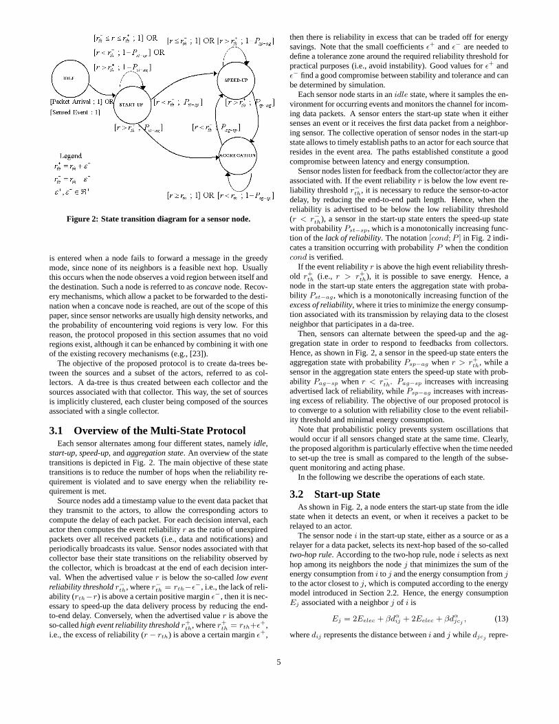
Figure 2: State transition diagram for a sensor node.
is entered when a node fails to forward a message in the greedymode, since none of its neighbors is a feasible next hop. Usuallythis occurs when the node observes a void region between itself andthe destination. Such a node is referred to asconcavenode. Recov-ery mechanisms, which allow a packet to be forwarded to the desti-nation when a concave node is reached, are out of the scope of thispaper, since sensor networks are usually high density networks, andthe probability of encountering void regions is very low. For thisreason, the protocol proposed in this section assumes that no voidregions exist, although it can be enhanced by combining it with oneof the existing recovery mechanisms (e.g., [23]).
The objective of the proposed protocol is to create da-treesbe-tween the sources and a subset of the actors, referred to as col-lectors. A da-tree is thus created between each collector and thesources associated with that collector. This way, the set ofsourcesis implicitly clustered, each cluster being composed of thesourcesassociated with a single collector.
3.1 Overview of the Multi-State ProtocolEach sensor alternates among four different states, namelyidle,
start-up, speed-up, andaggregation state. An overview of the statetransitions is depicted in Fig. 2. The main objective of these statetransitions is to reduce the number of hops when the reliability re-quirement is violated and to save energy when the reliability re-quirement is met.
Source nodes add a timestamp value to the event data packet thatthey transmit to the actors, to allow the corresponding actors tocompute the delay of each packet. For each decision interval, eachactor then computes the event reliabilityr as the ratio of unexpiredpackets over all received packets (i.e., data and notifications) andperiodically broadcasts its value. Sensor nodes associated with thatcollector base their state transitions on the reliability observed bythe collector, which is broadcast at the end of each decisioninter-val. When the advertised valuer is below the so-calledlow eventreliability thresholdr−th, wherer−th = rth−ǫ−, i.e., the lack of reli-ability (rth−r) is above a certain positive marginǫ−, then it is nec-essary to speed-up the data delivery process by reducing theend-to-end delay. Conversely, when the advertised valuer is above theso-calledhigh event reliability thresholdr+
th, wherer+th = rth+ǫ+,
i.e., the excess of reliability (r − rth) is above a certain marginǫ+,
then there is reliability in excess that can be traded off forenergysavings. Note that the small coefficientsǫ+ andǫ− are needed todefine a tolerance zone around the required reliability threshold forpractical purposes (i.e., avoid instability). Good valuesfor ǫ+ andǫ− find a good compromise between stability and tolerance and canbe determined by simulation.
Each sensor node starts in anidle state, where it samples the en-vironment for occurring events and monitors the channel forincom-ing data packets. A sensor enters the start-up state when it eithersenses an event or it receives the first data packet from a neighbor-ing sensor. The collective operation of sensor nodes in the start-upstate allows to timely establish paths to an actor for each source thatresides in the event area. The paths established constitutea goodcompromise between latency and energy consumption.
Sensor nodes listen for feedback from the collector/actor they areassociated with. If the event reliabilityr is below the low event re-liability thresholdr−th, it is necessary to reduce the sensor-to-actordelay, by reducing the end-to-end path length. Hence, when thereliability is advertised to be below the low reliability threshold(r < r−th), a sensor in the start-up state enters the speed-up statewith probabilityPst−sp, which is a monotonically increasing func-tion of thelack of reliability. The notation[cond; P ] in Fig. 2 indi-cates a transition occurring with probabilityP when the conditioncond is verified.
If the event reliabilityr is above the high event reliability thresh-old r+
th (i.e., r > r+th), it is possible to save energy. Hence, a
node in the start-up state enters the aggregation state withproba-bility Pst−ag, which is a monotonically increasing function of theexcess of reliability, where it tries to minimize the energy consump-tion associated with its transmission by relaying data to the closestneighbor that participates in a da-tree.
Then, sensors can alternate between the speed-up and the ag-gregation state in order to respond to feedbacks from collectors.Hence, as shown in Fig. 2, a sensor in the speed-up state enters theaggregation state with probabilityPsp−ag whenr > r+
th, while asensor in the aggregation state enters the speed-up state with prob-ability Pag−sp whenr < r−th. Pag−sp increases with increasingadvertised lack of reliability, whilePsp−ag increases with increas-ing excess of reliability. The objective of our proposed protocol isto converge to a solution with reliability close to the eventreliabil-ity threshold and minimal energy consumption.
Note that probabilistic policy prevents system oscillations thatwould occur if all sensors changed state at the same time. Clearly,the proposed algorithm is particularly effective when the time neededto set-up the tree is small as compared to the length of the subse-quent monitoring and acting phase.
In the following we describe the operations of each state.
3.2 Start-up StateAs shown in Fig. 2, a node enters the start-up state from the idle
state when it detects an event, or when it receives a packet toberelayed to an actor.
The sensor nodei in the start-up state, either as a source or as arelayer for a data packet, selects its next-hop based of the so-calledtwo-hop rule. According to the two-hop rule, nodei selects as nexthop among its neighbors the nodej that minimizes the sum of theenergy consumption fromi to j and the energy consumption fromjto the actor closest toj, which is computed according to the energymodel introduced in Section 2.2. Hence, the energy consumptionEj associated with a neighborj of i is
Ej = 2Eelec + βdαij + 2Eelec + βdα
jcj, (13)
wheredij represents the distance betweeni andj while djcj repre-
5

Algorithm 1 Start-up StatePseudo-code executed by a generic nodev in the start-up statemincost = ∞if ((I am a source) OR (I am a relayer)) then
for each of my neighborsNi dofor each actorsk do
if cost(v,Ni)+cost(Ni,sk) < mincost thenmincost=cost(v,Ni)+cost(Ni,sk)nexthop=Ni
end ifend for
end forend ifInform nexthop that it is a relayer
sents the distance betweenj and its closest actorcj . The two-hoprule selects as next hop the nodej associated with the minimumtwo-hop energy consumption. As a result, the source-actor pathwill be established by applying the two-hop rule iteratively. No-ticeably, since at each step the routing decision is independent ofprevious decisions, a packet intended for a certain actor byits gen-erating source can be transmitted towards another destination actorby an intermediate node in the end-to-end path. For this reason,the collector actor transmits its identifier on the reverse da-tree inorder to inform the source sensors about its own identity. The op-erations executed by a sensor node in the start-up state are detailedin Algorithm 1.
The two-hop rule produces loop-free paths, as stated below.
LEMMA 1. A next hop selected with thetwo-hop rulehas apos-itive absolute advance(see Def. 3).
As a consequence, the two-hop rule produces a loop-free pathbe-tween source and actor. We omit the proof of Lemma 1 because ofpage constraints.
3.3 Speed-up StateThe objective of the collaborative operation of nodes in thespeed-
up state is to minimize the number of hops between sources andactors. This is achieved by applying the Greedy Routing Scheme(GRS) [24] forwarding rule. According to GRS, each node sendsthe packet to the node closest to the destination within the trans-mission range. It is intuitive that this rule minimizes the numberof hops in the path, the distance travelled by the packet, andthenumber of transmissions of the same data packet, along with thechannel utilization. The pseudo-code of the operations executed bya sensor node in the speed-up state is reported in Algorithm 2.
Algorithm 2 Speed-up StatePseudo-code executed by a generic nodev in the speed-up statefor each neighborNi do
if (distance(v,Ni)> distance(v,next hop)) thennext hop = Ni
end ifend for
3.4 Aggregation StateThe objective of the aggregation state is to reduce the overall
energy consumption. To this end, sensor nodes in the aggregationstate take routing decisions that reduce the global energy consump-tion, by relying on the data fusion algorithm that we assume to be
implemented on each sensor. Since data packets can be aggregatedby any node in the network, the objective of a node in the aggrega-tion state is to route data to the closest node in its neighborhood thatis part of da-tree. This way, the incremental energy consumption tocollect the information from the considered sensor is minimized.
As previously discussed, after da-trees are established, each sen-sor knows which collector-actor it is associated with. By overhear-ing transmissions on the shared medium, each sensor learns whichof its neighbors are part of a da-tree (as some neighbor sensors maynot even be in the event-area) and which da-tree (if any) are theypart of, i.e., which collector actor are they associated with. Hence,nodev in the aggregation state first evaluates the cost of transmit-ting data to those among its neighbors that are part of a da-tree.This way, it can identify a minimum-cost neighbor, i.e., theneigh-borvmin that requires minimum energy consumption to be reachedamong those associated with one of the da-trees. Two different sit-uations can occur. The nodevmin can either be on the same da-treeasv, and hence associated with the same collector; or it can be inadifferent da-tree.
If vmin is in the same da-tree asv, vmin can be selected as nexthop by v only if it has a positive advance towards the collectorthat both nodes are associated with, i.e., ifvmin is closer thanvto the collector (see Def. 4). This guarantees loop freedom.Inthe resulting da-tree, every parent node is assured to have positiveadvance towards the collector, with respect to each child. Whenvmin is selected, the individual transmission cost forv is locallyminimized and the overall cost of the tree is thus reduced. Ifvmin
has no positive advance towards the collector with respect to v, vdeletesvmin from the list of possible next hops and determines anewvmin among the remaining neighbors.
The other possible situation occurs whenvmin is associated witha different collector thanv, i.e., v andvmin are in two differentda-trees. In this case,v is allowed to selectvmin as its next hoponly if v is a leaf in its da-tree andvmin has a positive advancetowards its actor with respect tov. This guarantees loop-freedomof the overall tree, as every parent node is assured to have a positiveadvance towards the actor with respect to each child. Conversely,it can be easily shown that if non-leaf nodes are allowed to switchfrom one da-tree to another, loops may be created, as the conditionthat every parent node is closer to the actor than each child doesnot necessarily hold anymore. The detailed operations executed bya sensor node in the aggregation state are reported in Algorithm 3.
Algorithm 3 Aggregation StatePseudo-code executed by a nodev in the aggregation statefor each of my transmitting neighborsNi do
if (cost(v,Ni) < cost(v,nexthop)) thenvmin=Ni
end ifend fors=actor(vmin)if (s == myactor) then
if distance(vmin,s)<distance(v,s) thennexthop=vmin
elsedeletevmin from list and restart Aggregation State
end ifelse ifI am a leaf then
nexthop=vmin
elsedeletevmin from list and restart Aggregation State
end if
6

4. ACTOR-ACTOR COORDINATION:PROBLEM FORMULATION
The objective of actor-actor coordination is to select the best ac-tor(s) to perform appropriate action on the event area. At the endof the sensor-actor coordination phase described in Section 3, oneor multiple actors, which we denote ascollectors, receive sensorreadings from sources that sense the event. These sources definetheevent area. The event area corresponds to theaction area, i.e.,the area where the actors should act. In particular, each collectorreceives data from a subset of the sources (cluster in Section 2).Each cluster area identifies a portion of the action/event area and isunder the responsibility of the corresponding collector. However,the collector may not be able to act on its entire responsiblearea,i.e., this area may not be totally within the collector’saction range.The action range defines the circular area where an actor is ableto act. Moreover, the collector may not be the “best” actor for thattask in terms ofaction completion timeand/orenergy consumption,where the former is the time to perform the action and the latter isthe required energy for the action. For these reasons, actor-actorcoordination is required before initiating actions.
DEFINITION 5. Theaction completion boundis the maximumallowed time from the instant when the event is sensed to the instantwhen the action is completed.
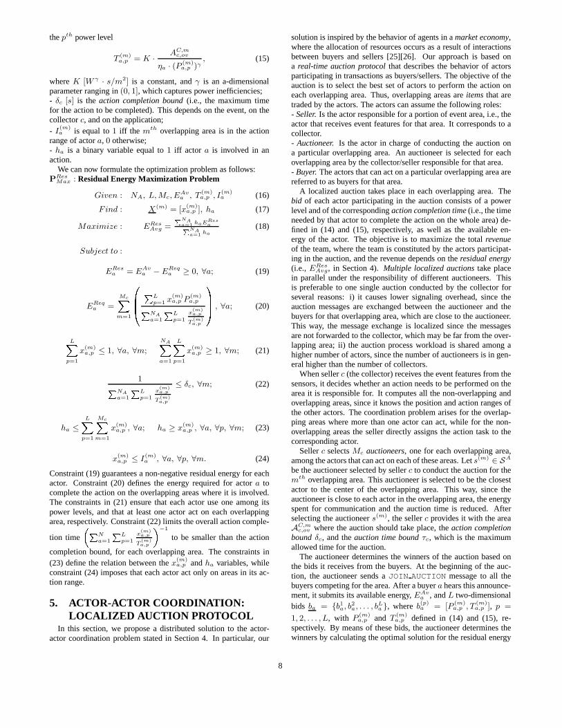
The coordination objective of each collector actor is to findtheoptimal actors to timely act on the portion of the event area underits own responsibility. In particular, if multiple actors can act ona certain area we refer to the area as anoverlapping area(regionareas numbered from1 to 8 in Fig. 3). On an overlapping areathe actor-actor coordination problem consists of selecting a subsetof the actors and their action powers to optimally divide theac-tion workload, so as to maximize theresidual energy3 of the actorswhile respecting theaction completion bound, in order to extendthe lifetime of the actors. We refer to an area where only one actorcan act asnon-overlapping area(unshaded regions in Fig. 3). Forsuch an area, the coordination problem simplifies to selecting thepower level for the actor that minimizes the energy consumptionwhile respecting the action completion bound. For this reason, weassume that the coordination problem involves only overlapping ar-eas and that the available energy of each actor is already discountedwith the energy needed to act on non-overlapping areas.
In Section 4.1 we present the action area model and the actormodel. These models are then used in the formulation of the prob-lem in Section 4.2.
4.1 Action Area and Actor ModelLet SA be the set of actors, withNA = |SA|, and letSC be
the set of collectors (SC ⊆ SA). As mentioned before, collectorsreceive data from sources (sensors), and from the source positionsthey can identify the portion of the whole event area they arere-sponsible for. By referring to Fig. 3, we introduce the followingnotations:- AD is the whole deployment area, which can be modelled as agrid of square cells.- Actor a ∈ SA has coordinatesCA
a = (xAa , yA
a ) and action rangeRa, which defines the circular areaAA
a where it can act;- AC
c is the cluster area that is under the responsibility ofcollector
c ∈ SC , and the whole event area is thusS|SC|
c=1 ACc ;
3Although actors are resource-rich nodes, the order of magnitudeof the energy required for actions is higher than that required forcommunication. Hence, it is important to save action energyinorder to extend the lifetime of actors.
1
2
34 5
6
7 8
32 ,
,
,1
45 ,
6 ,
78 ,
a
b
c
d
ea ba ea,b eb,ed eb db,,
dc
c
Cluster area
Action range actor/collector:: actor
Figure 3: Cluster area for collector c.
- AC,hc,nov andAC,m
c,ov are thehth non-overlappingand themth over-lapping areas, respectively, inside the portion of area under theresponsibility of collectorc. Hc represents the number of non-overlapping areas, whileMc represents the number of overlappingareas;- SA,m
c,ov is the set of actors that can act on themth overlapping areaAC,m
c,ov that is under the responsibility of collectorc.Each actora is characterized by the following parameters:
- Ra [m] is the action range ofa;- P Max
a [W ] is the maximum power that actora can use to performthe action. Actors can select their power amongL different levels
Pa,p =P Max
a
L· p, p = 1, 2, . . . , L (14)
wherePa,p is thepth power level for actora. As will be shownin (15), a higher power corresponds to a lower action completiontime;- ηa is theefficiencyof actora (see (15));- EAv
a [J ] is the available energy of actora.
4.2 Mixed Integer Non-Linear ProgramIn this section we formulate the actor-actor coordination problem
as aMixed Integer Non-Linear Program(MINLP). The objectiveis to find, for each portion of the event area, the subset of actorsthat maximizes the average residual energy of all actors involvedin the action, under the constraint of meeting the action comple-tion bound. We define the problem according to the following as-sumptions: i) the energy required to perform the action is orders ofmagnitude higher than the energy required for communication; ii)actors are able toselectivelyact on part of their action area, i.e., ifactora is chosen to act either on an overlapping or non-overlappingarea, this does not imply that it must act on the entire areaAA
a inits action rangeRa.
Let us introduce the following notations:- P
(m)a,p [W ] is thepth power level of actora for themth overlapping
areaAC,mc,ov , whose measure isAC,m
c,ov [m2];
- X(m) is a binary matrix whose element[x(m)a,p ] is equal to1 iff
actora acts on the overlapping areaAC,mc,ov using power levelP (m)
a,p ;
- T(m)a,p [s] is the action completion time for actora, characterized
by efficiencyηa, on themth overlapping area, when the actor uses
7
thepth power level
T (m)a,p = K ·
AC,mc,ov
ηa · (P (m)a,p )γ
, (15)
whereK [W γ · s/m2] is a constant, andγ is an a-dimensionalparameter ranging in(0, 1], which captures power inefficiencies;- δc [s] is the action completion bound(i.e., the maximum timefor the action to be completed). This depends on the event, onthecollectorc, and on the application;- I
(m)a is equal to1 iff the mth overlapping area is in the action
range of actora, 0 otherwise;- ha is a binary variable equal to1 iff actor a is involved in anaction.
We can now formulate the optimization problem as follows:P
ResMax : Residual Energy Maximization Problem
Given : NA, L, Mc, EAva , T
(m)a,p , I
(m)a (16)
Find : X(m) = [x(m)a,p ], ha (17)
Maximize : EResAvg =
PNAa=1 haERes
aPNAa=1 ha
(18)
Subject to :
EResa = EAv
a − EReqa ≥ 0, ∀a; (19)
EReqa =
McXm=1
0BB� PL
p=1 x(m)a,p P
(m)a,pPNA
a=1
PL
p=1
x(m)a,p
T(m)a,p
1CCA , ∀a; (20)
LXp=1
x(m)a,p ≤ 1, ∀a, ∀m;
NAXa=1
LXp=1
x(m)a,p ≥ 1, ∀m; (21)
1PNAa=1
PL
p=1
x(m)a,p
T(m)a,p
≤ δc, ∀m; (22)
ha ≤LX
p=1
McXm=1
x(m)a,p , ∀a; ha ≥ x(m)
a,p , ∀a, ∀p, ∀m; (23)
x(m)a,p ≤ I(m)
a , ∀a, ∀p, ∀m. (24)
Constraint (19) guarantees a non-negative residual energyfor eachactor. Constraint (20) defines the energy required for actora tocomplete the action on the overlapping areas where it is involved.The constraints in (21) ensure that each actor use one among itspower levels, and that at least one actor act on each overlappingarea, respectively. Constraint (22) limits the overall action comple-
tion time
�PN
a=1
PL
p=1
x(m)a,p
T(m)a,p
�−1
to be smaller than the action
completion bound, for each overlapping area. The constraints in(23) define the relation between thex
(m)a,p andha variables, while
constraint (24) imposes that each actor act only on areas in its ac-tion range.
5. ACTOR-ACTOR COORDINATION:LOCALIZED AUCTION PROTOCOL
In this section, we propose a distributed solution to the actor-actor coordination problem stated in Section 4. In particular, our
solution is inspired by the behavior of agents in amarket economy,where the allocation of resources occurs as a result of interactionsbetween buyers and sellers [25][26]. Our approach is based ona real-time auction protocolthat describes the behavior of actorsparticipating in transactions as buyers/sellers. The objective of theauction is to select the best set of actors to perform the action oneach overlapping area. Thus, overlapping areas areitemsthat aretraded by the actors. The actors can assume the following roles:- Seller.Is the actor responsible for a portion of event area, i.e., theactor that receives event features for that area. It corresponds to acollector.- Auctioneer. Is the actor in charge of conducting the auction ona particular overlapping area. An auctioneer is selected for eachoverlapping area by the collector/seller responsible for that area.- Buyer.The actors that can act on a particular overlapping area arereferred to as buyers for that area.
A localized auction takes place in each overlapping area. Thebid of each actor participating in the auction consists of a powerlevel and of the correspondingaction completion time(i.e., the timeneeded by that actor to complete the action on the whole area)de-fined in (14) and (15), respectively, as well as the availableen-ergy of the actor. The objective is to maximize the totalrevenueof the team, where the team is constituted by the actors participat-ing in the auction, and the revenue depends on theresidual energy(i.e., ERes
Avg, in Section 4).Multiple localized auctionstake placein parallel under the responsibility of different auctioneers. Thisis preferable to one single auction conducted by the collector forseveral reasons: i) it causes lower signaling overhead, since theauction messages are exchanged between the auctioneer and thebuyers for that overlapping area, which are close to the auctioneer.This way, the message exchange is localized since the messagesare not forwarded to the collector, which may be far from the over-lapping area; ii) the auction process workload is shared among ahigher number of actors, since the number of auctioneers is in gen-eral higher than the number of collectors.
When sellerc (the collector) receives the event features from thesensors, it decides whether an action needs to be performed on thearea it is responsible for. It computes all the non-overlapping andoverlapping areas, since it knows the position and action ranges ofthe other actors. The coordination problem arises for the overlap-ping areas where more than one actor can act, while for the non-overlapping areas the seller directly assigns the action task to thecorresponding actor.
Sellerc selectsMc auctioneers, one for each overlapping area,among the actors that can act on each of these areas. Lets(m) ∈ SA
be the auctioneer selected by sellerc to conduct the auction for themth overlapping area. This auctioneer is selected to be the closestactor to the center of the overlapping area. This way, since theauctioneer is close to each actor in the overlapping area, the energyspent for communication and the auction time is reduced. Afterselecting the auctioneers(m), the sellerc provides it with the areaAC,m
c,ov where the auction should take place, theaction completionboundδc, and theauction time boundτc, which is the maximumallowed time for the auction.
The auctioneer determines the winners of the auction based onthe bids it receives from the buyers. At the beginning of the auc-tion, the auctioneer sends aJOIN AUCTION message to all thebuyers competing for the area. After a buyera hears this announce-ment, it submits its available energy,EAv
a , andL two-dimensionalbids ba = {b1
a, b2a, . . . , bL
a }, whereb(p)a = [P
(m)a,p , T
(m)a,p ], p =
1, 2, . . . , L, with P(m)a,p and T
(m)a,p defined in (14) and (15), re-
spectively. By means of these bids, the auctioneer determines thewinners by calculating the optimal solution for the residual energy
8

maximization problemPResMax defined in Section 4.2. However, in
this case the problem is limited to the overlapping area the auction-eer is responsible for. This way, since the bids are submitted to theauctioneer only once, signaling overhead is reduced [27]. In mi-croeconomic theory, our auction mechanism can be classifiedas asingle-round sealed-bid auction[25], where each buyer submits itsbids in one shot irrespective of the bids from other buyers. In otherwords, the auctioneer receives the bids from the buyers onlyonceand then determines the winners (i.e., the optimal set of actors, andtheir power levels) accordingly.
6. PERFORMANCE EVALUATIONIn this section, we present the performance evaluation of the pro-
posed framework. In Section 6.1 we report the performance resultsfor the sensor-actor coordination, while in Section 6.2 we discussthe performance results for the actor-actor coordination.
6.1 Sensor-Actor CoordinationThe optimization problem presented in Section 2.3 was imple-
mented with AMPL [28], and solved with CPLEX [29], which usesa branch and bound algorithm to solve mixed integer linear prob-lems. The start-up, speed-up, and aggregation states, described inSection 3, were implemented in a C++ network-layer simulator andin the J-Sim Simulator [30], which implements the whole protocolstack of a sensor node, from physical to application layer, includ-ing 802.11 MAC, UDP transport and CBR traffic. All figures inthis section report 95% confidence intervals. We consideredthreedifferent simulation scenarios. In Scenario 1, the deployment areais circular with radius equal to20m. For each deployed sensor, thedistance from the center of the area and the angle are uniformlydistributed random variables. In Scenario 2, sensor nodes are ran-domly deployed in a square area of25m x 25m. The event area iscircular, with varying radius ranging in[2, 12]m in different simu-lations. The epicenter of the event area is randomly selected suchthat the event area completely falls into the terrain. Scenario 3 issimilar to Scenario 2, but the side of the square area is100m. Fouractors are randomly deployed in each scenario. As in [12], the sim-ulation parameters for the energy model in Section 2.2 are chosento beEelec = 50nJ/bit, β = 100pJ/bit/mα, α = 4. The trans-mission range of sensors is set to10m.
Since the global network behavior depends on several application-dependent parameters, we present performance evaluation resultsof particular network configurations that constitute upperand lowerbounds on the achievable performance. Hence, in this section werefer to start-up configuration, speed-up configuration, and aggre-gation configuration, as those configurations where all nodes arein the start-up, speed-up, and aggregation state, respectively. Thisallows us to describe how the evolution among different states im-pacts the overall network performance and show the benefits of theproposed solution without making it dependent on the choiceofparameters that govern the transitions among different states. Eval-uating and tuning the dependence of network dynamics on the para-meters that govern the transitions of nodes among the various statesis left for future work.
Figure 4 shows a comparison between the optimal solution to theevent-driven clustering problem described in Section 2 andthe en-ergy consumption in the start-up, speed-up, and aggregation con-figuration in Section 3, respectively, with varying event ranges.The overall network cost (energy needed to transmit one bit fromeach source to the actors) is reported in the figure. Noticeably, theoptimal solution is almost independent of the event range. Thishappens because of two contrasting phenomena. The number ofsources increases when the event range increases, leading to a po-
0 2 4 6 8 10 12 140
0.5
1
1.5
2
2.5x 10
4 Cost vs Event Range for optimum, start−up, speed−up and aggregation
Event Range [m]
Cos
t[nJ]
@ N
um. o
f sen
sors
=70
optimumstart−upspeed−upaggregation from start−upaggregation from speed−up
Figure 4: Scenario 1. Comparison of optimal solution, speed-up, start-up, and aggregation configuration with 70 nodes.
tentially higher energy consumption; conversely, since more nodesare involved, aggregation can be increasingly leveraged. These twotrends compensate each other leading to a flat curve. Conversely,the energy consumption in the start-up and speed-up configurationshighly increases with the event range. As also shown in Fig. 4,this can be partially compensated by the benefits of the aggregationstate. In particular, an aggregation configuration can be reachedboth from a start-up configuration and from a speed-up configura-tion. An aggregation configuration reached from a start-up config-uration leads to an almost-optimal energy consumption, where asby reaching the aggregation configuration from a speed-up configu-ration, the energy consumption can still be decreased consistently,but not as much as in the previous case. The structure of the da-trees after the start-up/speed-up configuration somehow constrainsan aggregation process based on simple logic and minimal inter-action among sensors. Hence, Fig. 4 motivates the design of ourthree-state distributed protocol for sensor-actor coordination. Infact, the distributed solution described in Section 3 adapts the struc-ture of the da-trees to reach an energy configuration that is betweenthe speed-up line and the aggregation from start-up line in Fig. 4.Depending on the required latency bound and reliability threshold,after a transient start-up configuration, a certain number of sensorswill enter the speed-up/aggregation state to reach a minimum en-ergy configuration, given the required reliability. When a higherreliability is required, the network will move towards a higher en-ergy/lower delay configuration, while when the required reliabilityis guaranteed with some margin, the network will move towards alower energy configuration.
In Figures 5 and 6 we plot the average energy consumption ver-sus the number of sensors and with different event ranges, for thestart-up, and aggregation configurations in Scenario 2. As can beseen, the energy expenditure of the aggregation configuration is twoorders of magnitude lower than in the start-up configuration(tensof thousands ofnJ versus hundreds ofnJ). This clearly shows thebenefits of the aggregation configuration. As can be seen in Fig. 6,the energy expenditure increases less than the number of sensors,i.e., by doubling the number of sensors the energy expenditure isless than doubled. Figure 7 reports the overall energy consumptionfor the speed-up configuration. Interestingly enough, not only isthe energy consumption of the speed-up configuration aroundoneorder of magnitude higher than in the start-up configuration; also,as already seen in Fig. 4, when the aggregation configurationis
9

0 100 200 300 400 500 600 700 800 900 10000
1
2
3
4
5
6
7
x 104 Start−up configuration: Cost vs no. of sensors for different Event Ranges
Number of sensors
Cos
t [nJ
]
Event Range=2 [m]Event Range=4 [m]Event Range=6 [m]Event Range=8 [m]Event Range=10 [m]Event Range=12 [m]
Figure 5: Scenario 2. Start-up configuration: Energy consump-tion vs. Number of sensors for different Event Ranges.
0 100 200 300 400 500 600 700 800 900 10000
200
400
600
800
1000
1200
1400
1600
1800
2000
2200Aggregation configuration from start−up: Cost vs no. of sensors for different Event Ranges
Number of sensors
Cos
t [nJ
]
Event Range=2 [m]Event Range=4 [m]Event Range=6 [m]Event Range=8 [m]Event Range=10 [m]Event Range=12 [m]
Figure 6: Scenario 2. Aggregation configuration: Energy con-sumption vs. Number of sensors for different Event Ranges.
reached from a speed-up configuration, the network converges toa less energy-efficient configuration with respect to the case whenthe aggregation configuration is reached directly from the start-upconfiguration. This is confirmed by Fig. 8, which shows that theorder of magnitude of the energy consumption is104 nJ for anaggregation configuration reached from a speed-up configuration.Conversely, as shown in Fig. 9, in Scenario 2 the average numberof hops of each source-actor pair is reduced from around 5 hopsfor the start-up configuration to less than 2 hops in the speed-upconfiguration. This explains the rationale for the design ofthe dis-tributed algorithm in Section 3. The speed-up configurationleadsto paths with lower delay (lower number of hops and straight to-wards the destination); however, since this is paid with a higherenergy consumption, the speed-up mechanism should be used onlywhen strictly necessary to provide the required reliability.
Figure 10 shows the overall energy consumption for the start-up, speed-up, and aggregation configurations in Scenario 3,with1000 nodes. Although the speed-up configuration can be seen tolead to a higher energy consumption, the energy consumptions ofthe start-up and speed-up configurations are in the same order ofmagnitude, i.e., the behavior of the speed-up configurationis sim-
0 100 200 300 400 500 600 700 800 900 10000
0.5
1
1.5
2
2.5
3
3.5
4
4.5x 10
5 Speed−up configuration: Cost vs no. of sensors for different Event Ranges
Number of sensors
Cos
t [nJ
]
Event Range=2 [m]Event Range=4 [m]Event Range=6 [m]Event Range=8 [m]Event Range=10 [m]Event Range=12 [m]
Figure 7: Scenario 2. Speed-up configuration: Energy con-sumption vs. Number of sensors for different Event Ranges.
0 100 200 300 400 500 600 700 800 900 10000
1
2
3
4
5
6
7
8
9
10x 10
4Aggregation configuration from speed−up: Cost vs no. of sensors for different Event Ranges
Number of sensors
Cos
t [nJ
]
Event Range=2 [m]Event Range=4 [m]Event Range=6 [m]Event Range=8 [m]Event Range=10 [m]Event Range=12 [m]
Figure 8: Scenario 2. Aggregation configuration reached fromspeed-up configuration: Energy consumption vs. Number ofsensors for different Event Ranges.
300 400 500 600 700 800 900 10000
1
2
3
4
5
6
7
8No. of hops vs no. of sensors for start−up and speed−up in 100mx100m and 25mx25m areas
Number of sensors
Ave
rage
num
ber
of h
ops
@ E
vent
Ran
ge=
6 m
speed−up in 100mx100mstart−up in 100mx100mspeed−up in 25mx25mstart−up in 25mx25m
Figure 9: Scenario 2-3. Average number of hops for start-upand speed-up configurations.
10

0 2 4 6 8 10 12 140
1
2
3
4
5
6x 10
4 Cost vs Event Range for start−up, speed−up and aggregation
Event Range [m]
Cos
t[nJ]
@ N
um. o
f sen
sors
=10
00
start−upspeed−upaggregation from start−upaggregation from speed−up
Figure 10: Scenario 3. Comparison of energy consumptions forstart-up, speed-up, and aggregation configurations with 1000sensors.
ilar to that of the start-up configuration. This happens whenthetransmission range of the nodes is short with respect to the distancebetween sensors and actors. In this case, a node in the start-up statetends to select the closest node to the destination (as it would do inthe speed-up configuration). In fact, when the distance between thesensor and the actor is much larger than the transmission range, thesecond term in the sum of the two-hop rule accounts for most oftheenergy expenditure (see Section 3.2). In fact, the distancebetweenthe sensor and any of its neighbors is short as compared to thedis-tance between the neighbor and the actor. Thus, the neighborisselected so as to minimize the second term, which, as can be easilydemonstrated, results in selecting the neighbor that is closest to thedestination (as also a node in the speed-up state does). Neverthe-less, Fig. 9 shows that the speed-up configuration still outperformsthe start-up configuration in terms of number of hops, while thisis achieved with a limited additional energy expenditure. More im-portantly, this is reflected in the distribution of packet delays, wherethe speed-up configuration always leads to lower delays thanthestart-up configuration. Figures 11 and 12 show a comparison ofpacket delays from sensor to actor in Scenario 3, with 400 nodes,between the speed-up and the start-up configuration when theeventrange is set to12m, which corresponds to 20 sources in average. InFigures 11(a)-11(b), sources generate 2 packets per second, each 32bytes long, for 200 seconds of simulation. The variability of packetdelays is reported as well as the cumulative average with time. Inthe start-up configuration, delays are shown to be high in thetran-sient phase at the beginning of the simulation. The average delay(thick line in the figure) converges to a value around0.3s. In thespeed-up configuration delays are much smaller, and their averageis below0.1s. Figures 11(c)-11(d) show the distribution of delaysin the same scenario. In the speed-up configuration (Fig. 11(d)),the delay is below0.5 s for almost100% of the packets, while inthe start-up configuration (Fig. 11(c)) the variability of delays ismuch higher and their value can be as high as2.5s.
Figures 12(a) and 12(b) refer to the same scenario, where eachsource generates 5 packets per second, for the start-up and speed-up configurations, respectively. Noticeably, while in the start-upconfiguration the network is congested (Fig. 12(a)), leading toextremely high values for the delays, this does not happen inthespeed-up configuration, where the delays are shown to be almostalways within1s (Fig. 12(b)). Note that, since the latency bound is
0 20 40 60 80 100 120 140 160 180 2000
0.5
1
1.5
2
2.5
Packet Delay for Start−up vs Time
Time [s]
Del
ay [s
]
DelayAverage Delay
(a)
0 20 40 60 80 100 120 140 160 180 2000
0.2
0.4
0.6
0.8
1
1.2
1.4
1.6
1.8
2
Packet Delay for Speed−up vs Time
Time [s]
Del
ay [s
]
DelayAverage Delay
(b)
0 0.5 1 1.5 2 2.50
50
100
150Distribution of data delivery delays in Start−up configuration
Delay [s]
No.
of r
ecei
ved
pack
ets
(c)
0 0.5 1 1.5 2 2.50
20
40
60
80
100
120
140
160
180
200Distribution of data delivery delays in Speed−up configuration
Delay [s]
No.
of r
ecei
ved
pack
ets
(d)
Figure 11: Scenario 3: Delays (a-b) and distribution of de-lays (c-d) for start-up and speed-up configurations, 400 sensors,event range =12m, sources generating 2 packets/s.
0 20 40 60 80 100 120 140 1600
10
20
30
40
50
60
70
80
90
100Distribution of data delivery delays in Start−up configuration
Delay [s]
No.
of r
ecei
ved
pack
ets
(a)
0 0.2 0.4 0.6 0.8 1 1.2 1.4 1.6 1.80
100
200
300
400
500
600
700
800Distribution of data delivery delays in Speed−up configuration
Delay [s]
No.
of r
ecei
ved
pack
ets
(b)
Figure 12: Scenario 3: Distribution of delays (a-b) for start-upand speed-up configurations, 400 sensors, event range =12m,sources generating 5 packets/s.
application dependent, in these simulations we do not drop packetsat intermediate nodes.
6.2 Actor-Actor CoordinationIn this section, we discuss some performance results of the actor-
actor coordination problem defined in Section 4. The model oftheMINLP problem was implemented in AMPL and solved with theMINLP solver available through the NEOS Optimization Server[17]. In Fig. 13, we compare the average residual energy withthree different solution approaches, namely, the optimal (Section4.2), 1-actor and localized auction(see Section 5). In the opti-mal solution, the best set of actors is chosen so that the averageresidual energy of the actors involved is maximized, while guar-anteeing that the action is completed before the action completiontime. In the 1-actor heuristic, the action is performed by one ac-tor only for each overlapping area, i.e., the actor with the highestavailable energy. In the localized auction each overlapping area istaken care of by an auctioneer that splits it among the actorsbasedon their bids, as discussed in Section 5. In the experiments per-formed, we concentrate on a scenario with three overlappingareas.
11

2 4 6 8 10 12 14 16660
680
700
720
740
760
780
800
820
840
860Available energy of involved Actors vs total number of Actors
Total number of Actors
Ava
ilabl
e en
ergy
of i
nvol
ved
Act
ors
[J]
OptimalSub−Optimal (1 Actor)Localized Auction
Figure 13: Available energy of the involved actors: optimalso-lution, localized auction, and 1-actor heuristic.
For the parameters defined in Section 4 we assumed the follow-ing values:AC,1
c,ov = 50m2, AC,2c,ov = 100m2, AC,3
c,ov = 150m2,P Max
a = 100W , L = 5, K/ηa = 1W γ · s/m2, δc = 10s,γ = 0.8. The values of the initial available energy of the actors arerandom variables uniformly distributed between800J and1000J .As shown in Fig. 13, the localized auction mechanism leads tonear-optimal residual energy, as each auctioneer calculates the op-timal solution separately for its overlapping area. However, thisgreatly simplifies the problem and can be achieved with localcom-munications among actors.
7. CONCLUSIONSWe presented a coordination framework for Wireless Sensor and
Actor Networks (WSANs), and discussed the sensor-actor andactor-actor coordination problems. We developed an optimal solution forthe sensor-actor coordination based on event-driven clustering, andformulated it as anInteger Linear Program (ILP). We also pro-posed a distributed solution that includes an adaptive mechanismto trade off energy consumption for delay when the event datahasto be delivered to the actors within pre-determined latencybounds.For the actor-actor coordination, an optimization model was de-fined for a class of coordination problems in which the area tobeacted upon is optimally split among different actors. The prob-lem was formulated as a mixed integer non-linear problem, and anauction-based localized solution of the problem was presented. Fu-ture work will be focused on extending the performance analysisof the proposed solutions, e.g., parameter fine tuning, and on gen-eralizing the framework to capture different applicationsscenarios,including those requiring mobile actors.
AcknowledgmentsThis work was supported by the NSF under contract ECS-0428329.
8. REFERENCES[1] I. F. Akyildiz and I. H. Kasimoglu, “Wireless sensor and actor networks:
Research challenges,”Ad Hoc Networks (Elsevier), vol. 2, no. 4, pp. 351–367,October 2004.
[2] T. He, J. Stankovic, C. Lu, and T. Abdelzaher, “SPEED: A real-time routingprotocol for sensor networks,” inProceedings of IEEE ICDCS, Providence,RI, USA, May 2003, pp. 46–55.
[3] C. Lu, B. M. Blum, T. F. Abdelzaher, J. A. Stankovic, and T.He, “RAP: areal-time communication architecture for large-scale wireless sensor
networks,” inProceedings of IEEE RTAS, San Jose, CA, USA, September2002.
[4] E. Felemban, C.-G. Lee, E. Ekici, R. Boder, and S. Vural, “Probabilistic QoSGuarantee in Reliability and Timeliness Domains in Wireless SensorNetworks,” inProceedings of IEEE INFOCOM 2005, Miami, FL, USA, Mar.2005.
[5] J. A. Stankovic, T. F. Abdelzaher, C. Lu, L. Sha, and J. Hou, “Real-timecommunication and coordination in embedded sensor networks,” Proceedingsof the IEEE, vol. 91, no. 7, pp. 1002–1022, 2003.
[6] I. F. Akyildiz, W. Su, Y. Sankarasubramaniam, and E. Cayirci, “Wirelesssensor networks: A survey,”Computer Networks (Elsevier), vol. 38, no. 4, pp.393–422, Mar. 2002.
[7] Y. Yu, B. Krishnamachari, and V. K. Prasanna, “Energy-latency tradeoffs fordata gathering in wireless sensor networks,” inProceedings of IEEEINFOCOM 2004, Hong Kong S.A.R., P.R. China, 2004.
[8] J. Li, J. Jannotti, D. D. Couto, D. Karger, and R. Morris, “A scalable locationservice for geographic ad hoc routing,” inProceedings of ACM/IEEEMobiCom 2000, Boston, Massachussets, 2000, pp. 120–30.
[9] R. Jain, A. Puri, and R. Sengupta, “Geographical routingusing partialinformation for wireless ad hoc networks,”IEEE Personal Communications,pp. 48–57, February 2001.
[10] J. Hightower and Borriello, “Location systems for ubiquitous computing,”IEEE Computer, vol. 34, no. 8, pp. 57–66, Aug. 2001.
[11] F. Kuhn, R. Wattenhofer, and A. Zollinger, “Worst-CaseOptimal andAverage-Case Efficient Geometric Ad-Hoc Routing,” inProceedings of ACMMobiHoc 2003, Annapolis, MD, USA, June 2003.
[12] W. Heinzelman, A. Chandrakasan, and H. Balakrishnan, “Anapplication-specific protocol architecture for wireless microsensor networks,”IEEE Transactions on Wireless Communications, vol. 1, no. 4, pp. 660–670,Oct. 2002.
[13] O. Younis and S. Fahmy, “Distributed clustering in ad-hoc sensor networks: Ahybrid, energy-efficient approach,” inProceedings of IEEE INFOCOM 2004,Hong Kong S.A.R., P.R. China, March 2004.
[14] V. Mhatre, C. Rosenberg, D. Kofman, R. Mazumdar, and N. Shroff, “Aminimum cost heterogeneous sensor network with a lifetime constraint,”IEEETransactions on Mobile Computing, vol. 4, no. 1, pp. 4–15, Jan. 2005.
[15] F. Kuhn, T. Moscibroda, and R. Wattenhofer, “Initializing newly deployed adhoc and sensor networks,” inProceedings of ACM MobiCom 2004,Philadelphia, PA, September 2004.
[16] R. K. Ahuja, T. L. Magnanti, and J. B. Orlin,Network Flows: Theory,Algorithms, and Applications. Englewood Cliffs, New Jersey: Prentice Hall,February 1993.
[17] J. Czyzyk, M. Mesnier, and J. More, “The NEOS server,”IEEE Journal onComputational Science and Engineering, vol. 5, pp. 68–75, 1998.
[18] B. Krishnamachari, D. Estrin, and S. Wicker, “The impact of data aggregationin wireless sensor networks,” inProceedings of IEEE DEBS 2002, Vienna,Austria, July 2002.
[19] G. J. Pottie and W. J. Kaiser, “Wireless integrated network sensors,”Communications of the ACM, vol. 43, pp. 51–58, May 2000.
[20] M. R. Garey and D. S. Johnson,Computer and Intractability. New York,NY: W. H. Freeman and Co., 1979.
[21] T. Melodia, D. Pompili, and I. F. Akyildiz, “On the Interdependence ofDistributed Topology Control and Geographical Routing in Ad Hoc andSensor Networks,”IEEE Journal of Selected Areas in Communications,vol. 23, no. 3, pp. 520–532, March 2005.
[22] B. Sundararaman, U. Buy, and A. Kshemkalyani, “Clock synchronization forwireless sensor networks: a survey,”Ad Hoc Networks (Elsevier), vol. 3, no. 3,pp. 281–323, May 2005.
[23] P. Bose, P. Morin, I. Stojmenovic, and J. Urrutia, “Routing with guaranteeddelivery in ad hoc wireless networks,”ACM Wireless Networks, vol. 7, no. 6,pp. 609–616, Nov. 2001.
[24] G. Finn, “Routing and addressing problems in large metropolitan-scaleinternetworks,” ISI res. rep ISU/RR- 87-180, Tech. Rep., March 1987.
[25] R. P. McAfee and J. McMillan, “Auctions and bidding,”Journal of EconomicLiterature, vol. 25, no. 2, pp. 699–738, June 1987.
[26] B. P. Gerkey and M. J. Mataric, “Sold!: Auction methods for multirobotcoordination,”IEEE Transactions on Robotics and Automation, vol. 18, no. 5,pp. 758–768, October 2002.
[27] P. Maille and B. Tuffin, “Multi-bid auctions for bandwidth allocation incommunication networks,” inProceedings of IEEE INFOCOM 2004, HongKong S.A.R., P.R. China, March 2004.
[28] R. Fourer, D. M. Gay, and B. W. Kernighan,AMPL: A Modeling Language forMathematical Programming. Duxbury Press / Brooks/Cole PublishingCompany, 2002.
[29] CPLEX solver. [Online]. Available: http://www.cplex.com[30] The J-Sim Simulator. [Online]. Available: http://www.j-sim.org/
12