a dual-band coupled resonator decoupling network for …klwu/pdf/ap201507.pdf · a dual-band...
TRANSCRIPT

IEEE TRANSACTIONS ON ANTENNAS AND PROPAGATION, VOL. 63, NO. 7, JULY 2015 2843
A Dual-Band Coupled Resonator DecouplingNetwork for Two Coupled Antennas
Luyu Zhao, Member, IEEE, and Ke-Li Wu, Fellow, IEEE
Abstract—A new decoupling scheme called dual-band cou-pled resonator decoupling network (CRDN) is presented. Byproperly designing the coupling coefficients between two pairsof coupled resonators, the network can effectively reduce themutual couplings between two coupled dual-band antennas in twobands simultaneously. The new scheme is proved by a practicalmicrostrip version of the device for two dual-band antennas work-ing at 2.4 and 5.2 GHz frequency bands. A compact planar dual-band CRDN consisting of a pair of dual-band open-loop squarering resonators is proposed. The measured scattering parame-ters of two coupled antennas with and without the dual-bandCRDN in free space (FS) and with hand phantom demonstratethat the isolation between the two antennas in both the low andhigh bands can be improved from 8 to 10 dB, respectively, tobelow 20 dB while maintaining a good matching performance. Thetotal efficiency and envelop correlation coefficient for the decou-pled antennas show a significant improvement as compared to thecoupled antenna case. The proposed dual-band CRDN scheme iseasy to be implemented in an integrated device, and is very attrac-tive for practical multiple input and multiple output (MIMO)applications.
Index Terms—Compact antenna array, coupled resonators,decoupling network, dual-band, multiple input and multiple out-put (MIMO), mutual coupling.
I. INTRODUCTION
N OWADAYS, more and more multistandard, multiband,and multimode wireless terminals with multiple anten-
nas have become popular on the market. Such devices includevarious wireless routers as well as multimode 2G/3G and LTEsmart phones and tablets. An obvious trend of these wirelessterminals is the use of multiple antennas for multiple inputand multiple output (MIMO) data access in a compact volume.When multiple antennas are installed in a size-constraint termi-nal, the physical limitation in separations of the antennas cannotbe easily transcended without sacrificing system performances.Furthermore, hostile interferences through mutual couplings inthe operating frequency bands become a bottleneck for furtherimproving the data rate of wireless systems.
Manuscript received July 24, 2014; revised January 19, 2015; acceptedMarch 18, 2015. Date of publication April 10, 2015; date of current versionJuly 02, 2015. This work was supported in part by the Postgraduate scholar-ship of The Chinese University of Hong Kong and in part by the Developmentand Reform Commission of Shenzhen Municipality under Grant Shen Fa Gai(2013) 1673. (Corresponding author: K.-L. Wu.)
The authors are with the Department of Electronic Engineering, TheChinese University of Hong Kong, Shatin, Hong Kong and also with theShenzhen Engineering Laboratory of Wireless Locating Technology andSystem, Shenzhen Research Institute, The Chinese University of Hong Kong,Shatin, Hong Kong (e-mail: [email protected]; [email protected]).
Color versions of one or more of the figures in this paper are available onlineat http://ieeexplore.ieee.org.
Digital Object Identifier 10.1109/TAP.2015.2421973
Significant attentions have been paid to mitigate the above-mentioned interferences in a multiple antenna system, which istermed as the antenna decoupling problem [1]–[12]. But suchendeavors have been mostly constrained to single-band appli-cations, which cannot fulfill the requirement for the multibandsystems. For example, emerging long-term evolution (LTE) sys-tems may operate in 700-MHz, 2.3-GHz, and 2.6-GHz bands,and the WLAN standards IEEE 802.11 a/b/g/n and ac operate at2.4- and 5-GHz bands with an advanced option of at least 2× 2MIMO.
Many of the existing methods for dual-band decouplingproblems simply extend the single-band decoupling methodto the context of a dual-band problem. For example, [13] and[14] intend to decouple a pair of dual-band antennas operatingat two bands (803–820 and 2440–2900 MHz in [13], UMTS(1920–2170 MHz), and WLAN (2400–2484 MHz) in [14])with a defected ground structure (DGS), respectively. As it isknown, DGSs are antenna-dependent and are not convenientfor dual-band applications. Not to mention that the footprint ofa DGS is quite large. Besides, these structures can have notice-able influence on the radiation patterns and efficiencies of thetwo antennas. The work in [15] uses an ad hoc structure toalter the current distribution of coupled antennas for decouplingtwo dual-band antennas. The structure is antenna-dependentand must be designed by intuition. Additionally, it is obviousthat currents induced on the line affect the radiation pattern.Another scheme using a lumped element decoupling networkfor coupled dual-band antennas is also proposed in [16] and[17]. A dual-band version of mode-decomposition technique[18], [19] and a combination of this technique with a passivedecoupling network technique [20] are also proposed. There arethree obvious issues in [18]–[20]: the network size is large; themodes’ Q and efficiency are different for different modes; andthe insertion loss of the decoupling network is not negligible.
Recently, a new concept named coupled resonator decou-pling network (CRDN) is proposed for wide-band decouplingof two or three element antenna arrays [11] and [12]. Based onthe concept of CRDN for single-band applications, a dual-banddecoupling technique using a dual-band CRDN is proposedin this paper. Comparing to the existing dual-band decou-pling solutions, the proposed scheme has the following uniquefeatures.
1) The dual-band CRDN can take various form factors inrealization, such as low temperature cofired ceramics(LTCC) and integrated passive devices (IPD), and can beintegrated in a very compact volume.
2) The CRDN can be synthesized and designed according tospecifications for given antenna characteristics.
0018-926X © 2015 IEEE. Personal use is permitted, but republication/redistribution requires IEEE permission.See http://www.ieee.org/publications_standards/publications/rights/index.html for more information.
2844 IEEE TRANSACTIONS ON ANTENNAS AND PROPAGATION, VOL. 63, NO. 7, JULY 2015
3) Since a dual-band CRDN is a filter-like structure innature, many advanced filter design methods can bedirectly inherited.
This paper is organized as follows. The working principleand basic design theory of the proposed dual-band CRDN willbe presented in Section II followed by one proof-of-conceptdesign example in Section III, in which a thorough investi-gation on the radiation performance of the decoupled array isconducted. Finally, conclusion is given in Section IV.
II. WORKING PRINCIPLE AND DESIGN THEORY
A. Network Model
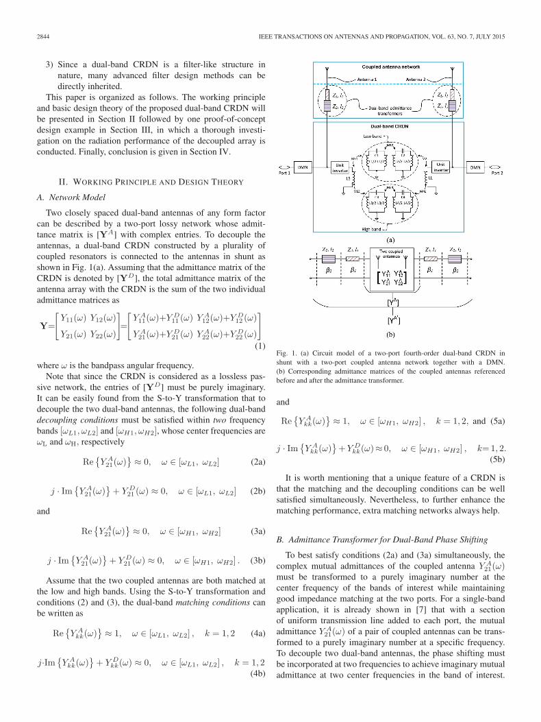
Two closely spaced dual-band antennas of any form factorcan be described by a two-port lossy network whose admit-tance matrix is [YA] with complex entries. To decouple theantennas, a dual-band CRDN constructed by a plurality ofcoupled resonators is connected to the antennas in shunt asshown in Fig. 1(a). Assuming that the admittance matrix of theCRDN is denoted by [YD], the total admittance matrix of theantenna array with the CRDN is the sum of the two individualadmittance matrices as
Y=
[Y11(ω) Y12(ω)
Y21(ω) Y22(ω)
]=
[Y A11(ω)+Y D
11 (ω) Y A12(ω)+Y D
12 (ω)
Y A21(ω)+Y D
21 (ω) Y A22(ω)+Y D
22 (ω)
]
(1)
where ω is the bandpass angular frequency.Note that since the CRDN is considered as a lossless pas-
sive network, the entries of [YD] must be purely imaginary.It can be easily found from the S-to-Y transformation that todecouple the two dual-band antennas, the following dual-banddecoupling conditions must be satisfied within two frequencybands [ωL1, ωL2] and [ωH1, ωH2], whose center frequencies areωL and ωH, respectively
Re{Y A21(ω)
} ≈ 0, ω ∈ [ωL1, ωL2] (2a)
j · Im{Y A21(ω)
}+ Y D
21 (ω) ≈ 0, ω ∈ [ωL1, ωL2] (2b)
and
Re{Y A21(ω)
} ≈ 0, ω ∈ [ωH1, ωH2] (3a)
j · Im{Y A21(ω)
}+ Y D
21 (ω) ≈ 0, ω ∈ [ωH1, ωH2] . (3b)
Assume that the two coupled antennas are both matched atthe low and high bands. Using the S-to-Y transformation andconditions (2) and (3), the dual-band matching conditions canbe written as
Re{Y Akk(ω)
} ≈ 1, ω ∈ [ωL1, ωL2] , k = 1, 2 (4a)
j·Im{Y Akk(ω)
}+ Y D
kk(ω) ≈ 0, ω ∈ [ωL1, ωL2] , k = 1, 2(4b)
Fig. 1. (a) Circuit model of a two-port fourth-order dual-band CRDN inshunt with a two-port coupled antenna network together with a DMN.(b) Corresponding admittance matrices of the coupled antennas referencedbefore and after the admittance transformer.
and
Re{Y Akk(ω)
} ≈ 1, ω ∈ [ωH1, ωH2] , k = 1, 2, and (5a)
j · Im{Y Akk(ω)
}+Y D
kk(ω)≈ 0, ω ∈ [ωH1, ωH2] , k=1, 2.(5b)
It is worth mentioning that a unique feature of a CRDN isthat the matching and the decoupling conditions can be wellsatisfied simultaneously. Nevertheless, to further enhance thematching performance, extra matching networks always help.
B. Admittance Transformer for Dual-Band Phase Shifting
To best satisfy conditions (2a) and (3a) simultaneously, thecomplex mutual admittances of the coupled antenna Y A
21(ω)must be transformed to a purely imaginary number at thecenter frequency of the bands of interest while maintaininggood impedance matching at the two ports. For a single-bandapplication, it is already shown in [7] that with a sectionof uniform transmission line added to each port, the mutualadmittance Y A
21(ω) of a pair of coupled antennas can be trans-formed to a purely imaginary number at a specific frequency.To decouple two dual-band antennas, the phase shifting mustbe incorporated at two frequencies to achieve imaginary mutualadmittance at two center frequencies in the band of interest.

ZHAO AND WU: DUAL-BAND CRDN FOR TWO COUPLED ANTENNAS 2845
Fig. 2. (a) Layout of two coupled dual-band antennas. (b) Simulated andmeasured S-parameters of the coupled antennas.
In this work, a two-section stepped-impedance transformer willbe used to accomplish this task.
In general, a two-section stepped-impedance transformer isformed by two transmission line sections with characteris-tic impedances Z1 and Z2 and physical lengths of l1 andl2, respectively. To simplify the design, Z1 = Z0 is cho-sen, where Z0 is the references port impedance. Define r =(Z2 − Z0) / (Z2 + Z0) as the ratio of the two characteristicimpedances. It is found that by slightly varying r value, onecan adjust the phase shift at the two bands independently in cer-tain extent without scarifying the matching condition too much.Therefore, the r value together with l1 and l2 can be optimizedto satisfy the required phase conditions in the two bands withminimum matching degradation.
As illustrated in Fig. 1(b), the admittance parameters of theoriginal coupled antennas YA is transformed to admittancesYA′
by the two-section stepped-impedance transformer. Settingthe real part of YA′
21 to zero at frequencies ωL0 and ωH0, whichare the center frequencies of the two bands, yields two transcen-dental equations, which are not convenient to solve analytically.Nevertheless, the solution can be obtained using a simple opti-mization tool in advanced design system [21]. To illustratethe process, a pair of practical dual-band monopole antennasas shown in Fig. 2(a) is used as an example. The two iden-tical printed dual-band monopoles are placed close to eachother on a 1.6-mm-thick FR4 substrate. The separation distanceDA = 9.8mm, which is less than 0.077 λ0 at 2.45 GHz and
TABLE IDIMENSIONS OF COUPLED AND DECOUPLED ANTENNAS (mm)
Fig. 3. Real part of mutual admittances (50-Ω termination) and return losses ofcoupled antennas for r = 0 and r = 0.18 at (a) the low band and (b) the highband.
0.17 λ0 at 5.25 GHz. The simulated and measured scatteringparameters of the coupled dual-band antennas are shown inFig. 2(b). The isolation between the antennas is around −8 dBat 2.45 GHz and −10 dB at 5.25 GHz, while the two antennasare well matched in the two bands. Detailed dimensions of thetest antennas are given in Table I.
To have a better understanding on the performance of theadmittance transformer, parameters r, l1, and l2 are designedto best satisfy conditions (2a) and (3a) while maintaining agood matching condition within the two bands. The resultantreal part of mutual admittance and the respective return lossesare obtained by ADS and are shown in Fig. 3. As comparedto the uniform transmission line case (r = 0) that only canfulfill (3a), a better solution for the two bands in this study isr = 0.18, l1 = 5.8 mm, and l2 = 10.7 mm with the respectivepropagation constant specified by the FR4 substrate. Aspresented in Fig. 3, the real part of the transformed mutualadmittance and the matching conditions after transformationusing the solution meet the requirements satisfactorily. It willbe shown later that the degradation in matching caused by

2846 IEEE TRANSACTIONS ON ANTENNAS AND PROPAGATION, VOL. 63, NO. 7, JULY 2015
the transformer can always be compensated by a dual-bandmatching network (DMN).
C. Proposed Dual-Band CRDN
Since a CRDN shares many common features with coupledresonator type of filters, many matured dual-band filter designtechniques can be utilized [22]. However, unlike specifying adual-band filter in terms of S-parameters, the requirements fora CRDN are imposed on admittance parameters.
The circuit model of the proposed dual-band CRDN is shownin Fig. 1(a), which is quite similar to the circuit model of asingle-band CRDN [11]. In both the low- and high-frequencybands, the relation between the coupling coefficients and theadmittance parameter of the dual-band CRDN can be foundfrom the nodal circuit analysis. According to [11], the inter-resonator coupling m12 has to be designed as large as the phys-ical implementation allows. This conclusion is also valid forthe dual-band scenario. Having fulfilled this requirement, themutual admittances of the CRDN can remain nearly constantin a relatively large frequency band and can be written as [11]
yD21(ω) ≈ −jmS1 ·m2L
Z0 ·m12, ω ∈ [ωL1, ωL2] (6)
where mS1 and m2L are the coupling coefficients of sourceto resonator 1 and resonator 2 to load, respectively. Theself-admittances can be simplified to
yD11(ω) = yD22(ω) ≈ 0, ω ∈ [ωL1, ωL2] (7)
which means that the CRDN is naturally matched near thecenter frequency.
By the same token, the admittance parameters at the highband can also be found to be
yD21(ω) ≈ −jmS3 ·m4L
Z0 ·m34, ω ∈ [ωH1, ωH2] (8)
and
yD11(ω) = yD22(ω) ≈ 0, ω ∈ [ωH1, ωH2] (9)
where m34, mS3, and m4L are the coupling coefficients of res-onator 3 to resonator 4, source to resonator 3, and resonator 4 toload, respectively. It is obvious from (6) and (8) that the abso-lute value of yD21 is mainly determined by the input and outputcouplings when the coupling between two coupled resonatorsis preset. The sign of yD21 is controlled by the sign of inter-resonator coupling m12 and m34. All these parameters need tobe designed properly for a given coupled antenna pair accordingto (2b) and (3b). Moreover, it is obvious from (7) and (9) thatthe matching conditions (4b) and (5b) are naturally satisfied fora dual-band CRDN with matched antennas.
To understand the functions of all the coupling coefficients,four combinations of coupling coefficients of the dual-bandCRDN shown in Table II are analyzed:Case 1: a CRDN with opposite inter-resonator coupling coeffi-
cients at low and high band (m12 = −m34);Case 2: a CRDN with the same inter-resonator coupling coef-
ficients at low and high band (m12 = m34);
TABLE IICOUPLING COEFFICIENTS OF CASES 1–4 IN FIG. 5
Fig. 4. Mutual admittances of a dual-band CRDN with different couplingcoefficients in the case studies.
Case 3: a CRDN with larger input/output coupling coefficientsat low and high band;
Case 4: a CRDN with small inter-resonator coupling coeffi-cients at low and high band.
As shown in Fig. 4, the comparison between Case 1 andCase 2 is consistent with (6) and (8) in that the sign of yD21is determined by the sign of m12 and m34; the compari-son between Cases 2 and 3 illustrates that the absolute valueof yD21 is mainly controlled by the input/output couplings;the comparison between Cases 3 and 4 reveals the fact thatthe inter-resonator couplings have to be designed as large aspossible for a relative flat yD21 within the bands of interest.
III. DESIGN EXAMPLE
To validate the design theory and to prove the concept,a microstrip version of the proposed dual-band CRDN isdesigned and tested to decouple the two dual-band coupledmonopole antennas depicted in Fig. 2(a).
The simulated S-parameters of the coupled antennas in thisdesign example are shown in Fig. 2(b). A two-section stepped-impedance transformer is designed in the first step using themethod discussed in Section II-B. The designed parametersof the transformer are listed in Table III. By introducing thestepped-impedance transformer, the real part of the mutual
admittance Re(YA′
21
)becomes zero at both 2.45 and 5.25 GHz
as shown in Fig. 5.The two coupled antennas with the stepped-impedance trans-
former are connected to the dual-band CRDN in shunt tocancel out the imaginary part of the mutual admittance inboth low and high bands. It can be seen from Fig. 5 that
Im(Y A′21
)= −0.0086 at 2.45 GHz and Im
(Y A′21
)= 0.0066

ZHAO AND WU: DUAL-BAND CRDN FOR TWO COUPLED ANTENNAS 2847
TABLE IIIPARAMETERS OF THE DESIGNED STEPPED-IMPEDANCE TRANSFORMERS
Fig. 5. Simulated mutual admittance parameters of the coupled antennas withand without the admittance transformer, and simulated mutual admittanceparameters of the CRDN at (a) the low band and (b) the high band.
TABLE IVCOUPLING COEFFICIENTS OF DESIGNED AND REALIZED CRDN
(FBW = 10%)
at 5.25 GHz. It is interesting to note that the imaginary part ofthe mutual admittance between two dual-band coupled anten-nas is in opposite sign in the two frequency bands in thisexample. Meanwhile, in the low band (2.4–2.48 GHz) as well
as the high band (5.15–5.35 GHz), the variation of Im(Y A′21
)
Fig. 6. (a) Layout of the dual-band CRDN and the dual-band antennas withthe CRDN. (b) Resonant frequency of fundamental mode fl and resonant fre-quency of the second mode fh of the dual-band resonator against the size ofthe square perturbation element. (c) Simulated and measured S-parameters ofthe decoupled antennas.
is not more than ±10% Therefore, (2b) and (3b) can be furthersimplified as
Y D21 (ω) = −jIm
{Y A21(ω)
} ≈ −jIm{Y A21(ωL)
},
ω ∈ [ωL1, ωL2] (10a)
and
Y D21 (ω) = −jIm
{Y A21(ω)
} ≈ −jIm{Y A21(ωH)
},
ω ∈ [ωH1, ωH2] . (10b)
Based on (10), the coupling coefficients are obtained from(6) and (8) for both the low and high bands and are listed in
2848 IEEE TRANSACTIONS ON ANTENNAS AND PROPAGATION, VOL. 63, NO. 7, JULY 2015
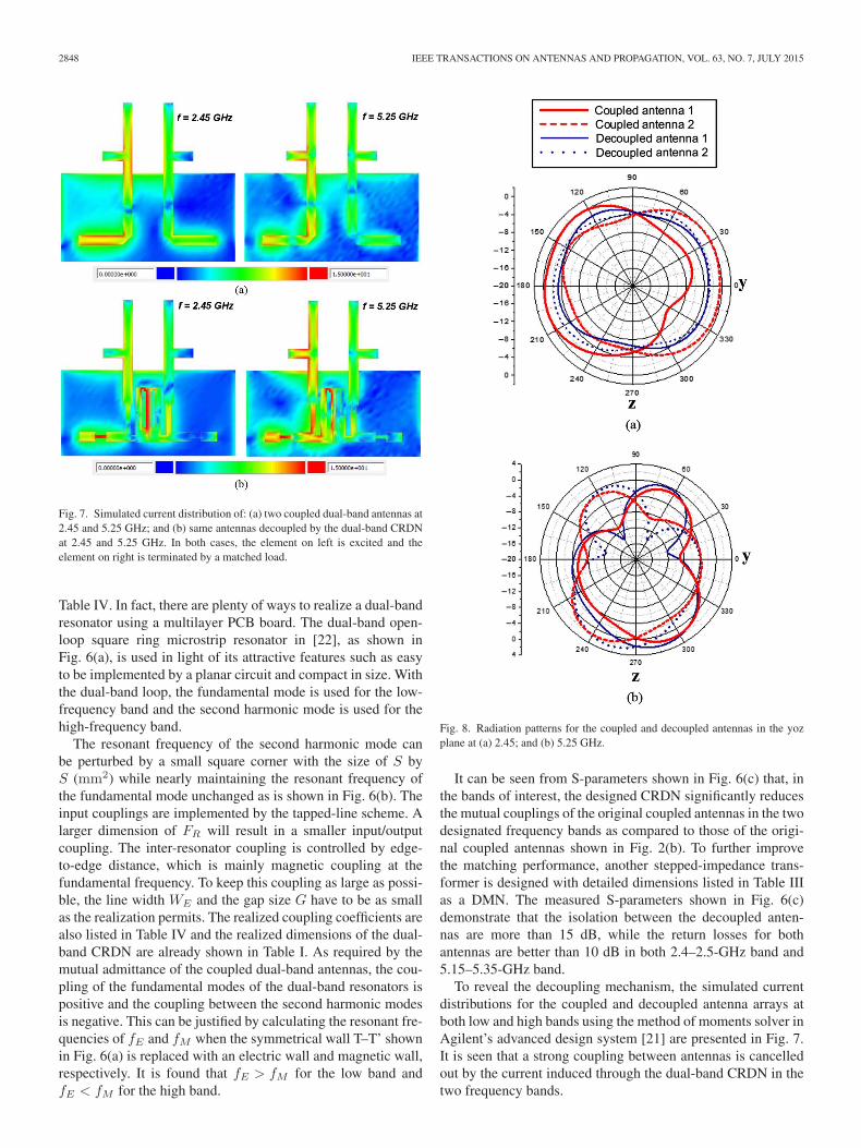
Fig. 7. Simulated current distribution of: (a) two coupled dual-band antennas at2.45 and 5.25 GHz; and (b) same antennas decoupled by the dual-band CRDNat 2.45 and 5.25 GHz. In both cases, the element on left is excited and theelement on right is terminated by a matched load.
Table IV. In fact, there are plenty of ways to realize a dual-bandresonator using a multilayer PCB board. The dual-band open-loop square ring microstrip resonator in [22], as shown inFig. 6(a), is used in light of its attractive features such as easyto be implemented by a planar circuit and compact in size. Withthe dual-band loop, the fundamental mode is used for the low-frequency band and the second harmonic mode is used for thehigh-frequency band.
The resonant frequency of the second harmonic mode canbe perturbed by a small square corner with the size of S byS (mm2) while nearly maintaining the resonant frequency ofthe fundamental mode unchanged as is shown in Fig. 6(b). Theinput couplings are implemented by the tapped-line scheme. Alarger dimension of FR will result in a smaller input/outputcoupling. The inter-resonator coupling is controlled by edge-to-edge distance, which is mainly magnetic coupling at thefundamental frequency. To keep this coupling as large as possi-ble, the line width WE and the gap size G have to be as smallas the realization permits. The realized coupling coefficients arealso listed in Table IV and the realized dimensions of the dual-band CRDN are already shown in Table I. As required by themutual admittance of the coupled dual-band antennas, the cou-pling of the fundamental modes of the dual-band resonators ispositive and the coupling between the second harmonic modesis negative. This can be justified by calculating the resonant fre-quencies of fE and fM when the symmetrical wall T–T’ shownin Fig. 6(a) is replaced with an electric wall and magnetic wall,respectively. It is found that fE > fM for the low band andfE < fM for the high band.
Fig. 8. Radiation patterns for the coupled and decoupled antennas in the yozplane at (a) 2.45; and (b) 5.25 GHz.
It can be seen from S-parameters shown in Fig. 6(c) that, inthe bands of interest, the designed CRDN significantly reducesthe mutual couplings of the original coupled antennas in the twodesignated frequency bands as compared to those of the origi-nal coupled antennas shown in Fig. 2(b). To further improvethe matching performance, another stepped-impedance trans-former is designed with detailed dimensions listed in Table IIIas a DMN. The measured S-parameters shown in Fig. 6(c)demonstrate that the isolation between the decoupled anten-nas are more than 15 dB, while the return losses for bothantennas are better than 10 dB in both 2.4–2.5-GHz band and5.15–5.35-GHz band.
To reveal the decoupling mechanism, the simulated currentdistributions for the coupled and decoupled antenna arrays atboth low and high bands using the method of moments solver inAgilent’s advanced design system [21] are presented in Fig. 7.It is seen that a strong coupling between antennas is cancelledout by the current induced through the dual-band CRDN in thetwo frequency bands.

ZHAO AND WU: DUAL-BAND CRDN FOR TWO COUPLED ANTENNAS 2849
Fig. 9. (a) Measured total efficiencies, and (b) measured ECCs (absolute value)of coupled and decoupled dual-band antennas in FS and with hand phantom(HAND).
The radiation performances of the decoupled antennas inFig. 6(a) and its coupled counterpart in Fig. 2(a) are also mea-sured using the in-house SATIMO SG128 spherical near-fieldscanner [23] in an ISO17025 accredited laboratory. The radi-ation power patterns of both coupled and decoupled antennasare given in Fig. 8 for both low and high bands. Their totalefficiencies are compared in Fig. 9(a). In the low band, thedecoupled antenna pair has an improvement of around 3%–9%on top of about 70% in total efficiency, while in the high band,the improvement in total efficiency is not very obvious sincethe dielectric losses in the FR4 substrate tend to be dominantin the high band (5.2 GHz). It is expected that using a low-losssubstrate can improve the efficiency more obviously, especiallyin the high band.
The envelope correlation coefficient (ECC) of the two anten-nas obtained from the measured complex far-field patterns overa sphere is an important figure of merit for benchmarking theperformance of two coupled antennas in a Rayleigh fadingchannel. The coefficient is defined as [24]
ρe =
∣∣∣∣∫∫4π
[⇀E1(θ, φ) · ⇀E2(θ, φ)]dΩ
∣∣∣∣2
∫∫4π
|⇀E1(θ, φ)|2dΩ∫∫4π
|⇀E2(θ, φ)|2dΩ(11)
where⇀E1(θ, φ) · ⇀E2(θ, φ) =Eθ1(θ, φ)E
∗θ2(θ, φ)
+ Eφ1(θ, φ)E∗φ2(θ, φ).
(12)
⇀Ei(θ, φ) is the electric field radiated by antenna i with another
antenna terminated by a matched load.It is known that a lower envelope correlation leads to a larger
channel capacity. As demonstrated by Fig. 9(b), in the case
Fig. 10. (a) Measurement setup for antennas with hand phantom. (b) Measuredscattering parameters of coupled and decoupled arrays with hand phantom.
of free space (FS), the decoupled antenna pair has its ECCimproved from 0.02 to 0.004 in the low band and 0.02 to 0.002in the high band as compared to its coupled counterpart.
In real-world applications, MIMO antennas suffer from theinterferences from human body, especially the hands. To havea better insight on the performance of the decoupled antennaswith hand interactions, the SPEAG hand phantom for mono-block phones SHO V2RB/LB is used [25] to emulate thehand effect with experiment setup shown in Fig. 10(a). TheS-parameters for the coupled and decoupled antenna arraysshown in Figs. 2(a) and 6(a) are superposed in Fig. 10(b).
Since the hand phantom acts as a lossy dielectric medium inclose proximity of the antennas, the resonant frequencies for allantennas, regardless of coupled and decoupled, are shifted anddeteriorated.
The measured total efficiencies and ECCs for the coupled anddecoupled array with hand phantom are also shown in Fig. 9.It is understandable that the total efficiencies drop significantlyfor both coupled and decoupled arrays due to the lossy nature ofthe hand. Nevertheless, the decoupled array still shows around10% improvement in efficiency in the low band. The decoupledantenna pair has its ECC improved from 0.23 to 0.13 in thelow band and 0.04 to 0.008 in the high band as compared to itscoupled counterpart.
2850 IEEE TRANSACTIONS ON ANTENNAS AND PROPAGATION, VOL. 63, NO. 7, JULY 2015
IV. CONCLUSION
A dual-band CRDN is proposed in this paper. The networkaims at mitigating the strong mutual coupling between twodual-band antennas. A complete design theory of a dual-bandCRDN and a practical realization in a planar microstrip formare presented in this paper. The network is compact in size andcost-effective in implementation. Although a pair of symmetricarray is used in discussion, the decoupling approach is gen-eral for any antenna form factors including asymmetric arrays.While reducing the unwanted mutual couplings, the CRDN alsoprovides a good matching performance, which makes it verypromising to be used in an MIMO system in a wireless ter-minal. The research on an integrated module of the proposedCRDN network for decoupling of two dual-band antennas is onthe way.
REFERENCES
[1] Z. N. Chen, X. N. Low, and T. S. P. See, “Analysis and optimizationof compact suspended plate MIMO antennas,” IEEE Trans. AntennasPropag., vol. 59, no. 1, pp. 263–270, Jan. 2011.
[2] J. C. Coetzee and Y. Yu, “Port decoupling for small arrays by means of aneigenmode feed network,” IEEE Trans. Antennas Propag., vol. 56, no. 6,pp. 1587–1593, Jun. 2008.
[3] C. Volmer, J. Weber, R. Stephan, K. Blau, and M. A. Hein, “Aneigen-analysis of compact antenna arrays and its application to portdecoupling,” IEEE Trans. Antennas Propag., vol. 56, no. 2, pp. 360–370,Feb. 2008.
[4] J. Weber, C. Volmer, K. Blau, R. Stephan, and M. A. Hein, “Miniaturizedantenna arrays using decoupling networks with realistic elements,” IEEETrans. Microw. Theory Technol., vol. 54, no. 6, pp. 2733–2740, Jun. 2006.
[5] L. K. Yeung and Y. E. Wang, “Mode-based beamforming arrays forminiaturized platforms,” IEEE Trans. Microw. Theory Technol., vol. 57,no. 1, pp. 45–52, Jan. 2009.
[6] J. B. Andersen and H. H. Rasmussen, “Decoupling and descatteringnetworks for antennas,” IEEE Trans. Antennas Propag., vol. 24, no. 6,pp. 841–846, Nov. 1976.
[7] S. Chang, Y.-S. Wang, and S.-J. Chung, “A decoupling technique forincreasing the port isolation between strongly coupled antennas,” IEEETrans. Antennas Propag., vol. 56, no. 12, pp. 3650–3658, Dec. 2008.
[8] A. Diallo, C. Luxey, P. L. Thuc, R. Staraj, and G. Kossiavas, “Study andreduction of the mutual coupling between two mobile phone PIFAs oper-ating in the DCS1800 and UMTS bands,” IEEE Trans. Antennas Propag.,vol. 54, no. 11, pp. 3063–3073, Nov. 2006.
[9] F. Yang and Y. R. Samii, “Microstrip antennas integrated with elec-tromagnetic band-gap EBG structures: A low mutual coupling designfor array applications,” IEEE Trans. Antennas Propag., vol. 51, no. 10,pp. 2936–2946, Oct. 2003.
[10] C. Y. Chiu, C. H. Cheng, R. D. Murch, and C. R. Rowell, “Reduction ofmutual coupling between closely-packed antenna element,” IEEE Trans.Antennas Propag., vol. 55, no. 6, pp. 1732–1738, Jun. 2007.
[11] L. Zhao, L. K. Yeung, and K.-L. Wu, “A coupled resonator decouplingnetwork for two-element compact antenna arrays in mobile terminals,”IEEE Trans. Antennas Propag., vol. 62, no. 5, pp. 2767–2776, May 2014.
[12] L. Zhao and K.-L. Wu, “A broadband coupled resonator decouplingnetwork for a three-element compact array,” in Proc. IEEE MTT-S Int.Microw. Symp., Jun. 2013, pp. 1–3.
[13] M. S. Sharawi, A. B. Numan, M. U. Khan, and D. N. Aloi, “Adual-element dual-band MIMO antenna system with enhanced isolationfor mobile terminals,” IEEE Antennas Wireless Propag. Lett., vol. 11,pp. 1006–1009, Aug. 2012.
[14] Y. Ding, Z. Du, K. Gong, and Z. Feng, “A novel dual-band printeddiversity antenna for mobile terminals,” IEEE Trans. Antennas Propag.,vol. 55, no. 7, pp. 2088–2096, Jul. 2007.
[15] X. M. Ling and R. L. Li, “A novel dual-band MIMO antenna arraywith low mutual coupling for portable wireless devices,” IEEE AntennasWireless Propag. Lett., vol. 10, no. 1, pp. 1039–1042, Sep. 2011.
[16] X. Tang, K. Mouthaan, and J. C. Coetzee, “Dual-band decoupling andmatching network design for very closely spaced antennas,” in Proc. Eur.Microw. Conf., 2012, pp. 49–52.
[17] C.-Y. Lui, Y.-S. Wang, and S.-J. Chung, “Two nearby dual-band antennaswith high port isolation,” presented at the IEEE Antennas Propag. Symp.Dig., San Diego, CA, USA, Jul. 2008.
[18] P.-L. Chi, C.-J. Lee, and T. Itoh, “A compact dual-band metamaterials-based rat-race coupler for a MIMO system application,” in Proc. IEEEMTT-S Int. Microw. Symp. Dig., Jun. 15–20, 2008, pp. 667–670.
[19] P. Chi and T. Itoh, “Miniaturized dual-band directional couplers usingcomposite right/left-handed transmission structures and their applicationsin beam pattern diversity systems,” IEEE Trans. Microw. Theory Technol.,vol. 57, no. 5, pp. 1207–1215, May 2009.
[20] K.-C. Lin, C.-H. Wu, C.-H. Lai, and T.-G. Ma, “Novel dual-banddecoupling network for two-element closely spaced array using synthe-sized microstrip lines,” IEEE Trans. Antennas Propag., vol. 60, no. 11,pp. 5118–5128, Nov. 2012.
[21] Advanced Design System, Version 2012.08, Agilent Technol. Inc., SantaClara, CA, USA, 2012.
[22] J.-S. Hong and M. J. Lancaster, Microstrip Filters for RF/MicrowaveApplications, 2nd ed. Hoboken, NJ, USA: Wiley, 2011, ch. 7–10.
[23] [Online]. Available: http://www.satimo.com/[24] R. G. Vaughan and J. B. Andersen, “Antenna diversity in mobile commu-
nications,” IEEE Trans. Veh. Technol., vol. 36, no. 4, pp. 149–172, Nov.1987.
[25] [Online]. Available: http://www.speag.com/
Luyu Zhao (S’09–M’14) was born in Xi’an, China,in 1984. He received the B.Eng. degree from theXidian University, Xi’an, China, in 2007, and thePh.D. degree from The Chinese University of HongKong, Shatin, Hong Kong, in 2014, all in electricalengineering.
Currently, he is a Postdoctoral Fellow withThe Chinese University of Hong Kong. From2007 to 2009, he was a Research Assistant withthe National Key Laboratory of Antennas andMicrowave Technology, Xidian University, where he
was involved with software and hardware implementation of RF identification(RFID) technologies. His research interests include design and application ofmultiple antenna systems for the next-generation mobile communication sys-tems as well as innovative passive RF and microwave components, circuits,and systems.
Dr. Zhao was the recipient of the Best Student Paper Award of 2013 IEEE14th HK AP/MTT Postgraduate Conference.
Ke-Li Wu (M’90–SM’96–F’11) received the B.S.and M.Eng. degrees from the Nanjing University ofScience and Technology, Nanjing, China, in 1982 and1985, respectively, and the Ph.D. degree from theLaval University, Quebec, QC, Canada, in 1989, allin electrical engineering.
From 1989 to 1993, he was a Research Engineerand a Group Manager with the CommunicationsResearch Laboratory, McMaster University,Hamilton, ON, Canada. In March 1993, he joined theCorporate R&D Division, COM DEV International,
where he was a Principal Member of Technical Staff. Since October 1999, hehas been with The Chinese University of Hong Kong, Shatin, Hong Kong,where he is a Professor and the Director of the Radiaofrequency RadiationResearch Laboratory (R3L). His research interests include partial elementequivalent circuit (PEEC) and derived physically expressive circuit (DPEC)EM modeling of high-speed circuits, RF and microwave passive circuitsand systems, synthesis theory and practices of microwave filters, antennasfor wireless terminals, LTCC-based multichip modules (MCMs), and RFidentification (RFID) technologies.
Prof. Wu is a member of the IEEE MTT-8 subcommittee (Filters and PassiveComponents) and also serves as a TPC member for many prestigious interna-tional conferences including International Microwave Symposium. He was anAssociate Editor of IEEE TRANSACTIONS ON MTT from 2006 to 2009. Hewas the recipient of the 1998 COM DEV Achievement Award for the develop-ment of exact EM design software of microwave filters and multiplexers andAsia Pacific Microwave Conference Prize in 2008 and 2012, respectively.