a flexible dc-dc converter for the battery - dc bus
TRANSCRIPT

Thang P.N., Vinh V.T., and Vinh N.T. / International Energy Journal 20 (2020) 581 – 594
www.rericjournal.ait.ac.th
581
Abstract – This study proposes a single, coupling magnetic (CM), high efficiency, high step-up/down bidirectional DC–DC converter. The proposed converter is composed of a bidirectional coupling magnetic boost and bidirectional buck non - isolated. The output terminals of the CM-boost converter and switched-capacitor cell are connected together in series to obtain the required voltage step-up of the distributed renewable energy source. A transformer coupled combined two type boost flyback converter is used to harness power from PV, while bidirectional buck-boost converter is used to harness power from PV and DC link along with battery charging/discharging control. The proposed topology achieves a genuine on–off interleaved energy transfer at the transformer core and windings, thus providing an excellent utilization ratio. The proposed converter architecture has reduced number of power conversion stages with less component count, and reduced losses compared to existing grid-connected hybrid systems. This improves the efficiency and reliability of the system. Keywords – DC-DC converter, energy storage, multiport converter, photovoltaic (PV) generation system, power management strategy.
1 1. INTRODUCTION
The future energy crisis and climate change, then the solution of the renewable energy resources is necessary. Over the last 10 years solar technology grew fast worldwide. However, solar energy, one of the most promising energy sources, exhibits a fluctuating power generation profiles because its generation is dependent on external environmental parameters, such as temperature and radiation [1]-[2]. To derive the multi-port DC-DC converters, a series or parallel configuration is employed on the input side. Some components can be shared by each input port [3]-[6]. In [7] explore the need of transforming the power grid into a more reliable, secure, efficient and clean network. The present paper focuses solely on the use of PV system in the smart grid and shows its importance and utility. PV is used worldwide in many applications, from the major cities in the developed countries to primary rural villages in developing states. The PV system is illustrated as a means to generate electricity by utilizing directly from the sunlight. The PV is a cost-effective alternative in rural areas where extending a utility power line is very expensive. The PV has less operating cost and takes less maintenance, generate electricity without polluting the environment and without creating disturbance. The PV can be integrated into a grid with other types of generators [8]. These are considered as advantages of the PV.
*Hung Yen University of Technology and Education, Hung Yen, Vietnam. + Dong Thap University, Dong Thap, Vietnam. # Quang Ninh University of Industry, Quang Ninh, Vietnam. 1Corresponding author;
Tel: + 84 0912 224 112. E-mail: [email protected]
Many applications demand a converter with a bidirectional power flow capability to handle energy flowing from or to the source. The main focus of this thesis a converter with a configuration that allows this bidirectional power flow capability. The major applications of a DC-DC converter is in battery charging/discharging devices, uninterruptible power supplies, hybrid renewable energy [9]-[10]. In [11], the authors propose a three port bidirectional DC-DC converter for Photovoltaic systems with energy storage. In this, the output level can be changed almost continuously with magnetic components. One of the major benefits of this magnetic system is that step up high voltage output is possible in comparison to conventional solutions.
Fig. 1. Block diagram of the proposed DC grid-connected
PV plant with energy storage system. On some PV projects which are connected to a weak power grid or have no access to a power grid, renewable energy sources and energy storage systems are commonly used together. In this case, a multiport bidirectional converter is preferable. Figure 1 shows the power converter system framework of the photovoltaic power generation system. This framework combines a maximum power point tracking controller of the PV energy supply for the battery and DC link/load, and a bidirectional buck-boost converter equipped with a charge and discharge control function for the battery [12]-[16]. The battery charge and discharge controller employs a bidirectional buck-boost converter that
A Flexible DC-DC Converter for the Battery - DC Bus Renewable Energy System
Pham Ngoc Thang*, Vo Thanh Vinh*,+ and Nguyen The Vinh#, 1
www.rericjournal.ait.ac.th

Thang P.N., Vinh V.T., and Vinh N.T. / International Energy Journal 20 (2020) 581 – 594
www.rericjournal.ait.ac.th
582
simultaneously exhibits the energy conversion characteristics of buck and coupling magnetic boost converters [17]-[21]. Thus, the energy conversion efficiency is significantly increased. Furthermore, this converter in the system framework provides not only battery energy storage functions, but also facilitate auxiliary power supply at the DC link/load terminal (DC link can connect with the renewable sources other). By implementing the system characteristics shown in Figure 1, the power supply can be managed and controlled.
2. THE CONVERTER PROPOSED
The proposed converter topology is illustrated in Figure 2. This converter can interface three different ports, including battery, PV panels and the DC link/load. The port connected battery is bidirectional. It allows operation three cases as: 1. single-input/single-output; 2.
single-input/double-output; 3. double-input/single-output converter, fulfilling in that way all the required power flows sketched in Figure 2. This converter is a double-input/double-output converter. The presented structure utilizes two unidirectional power switches (M1, M4) and two bidirectional power switches (M2, M3). This reduction in power devices used, makes a significant impact on the power loss associated with the switches. The pulse width modulation strategy for each scenario is explained for the control of the duty cycle that results in the switching of the power switches. The recovery stage is constituted by the diode D1 and the capacitor C1 for three scenarios will be explained in the section 2.1 (full explanation of the operating modes of this recovery stage is fully described by Vinh et al., 2015 [17]).
Fig. 2. Diagram bidirectional DC-DC converter proposed.
A binary variable is associated with each switch. This gives a total of sixteen switching states arising from the combination of these four switches. Many of these states are forbidden. A prohibited state is one which creates a situation of either a short circuit or one in which the switches would have to absorb (or dissipate) the inductive energy instantly. Hence, these states are to be avoided. The switching states are given in Table 1. The states are arranged according to the characteristics of the PV source. Six operation states of the converter are:
2.1 Operation State 1
During state 1: shown in the Figure 3, the energy of the source PV is full, and the battery is disconnected, the PV provides energy to the DC link/load as well as to the inductor L1, L21 and L22 charge/ discharge. In this case, the inductor L3 does not charge/discharge. Only one gate signals with the duty ratio (d1) is applied to M1 while M2, M3 and M4 are turned off. In the steady-state operation, there are four modes in one switching period,
the steady-state waveforms of these modes are depicted in Figure 4. Table 1. Topological states obtained with the states of the power switches. State M1 M2 M3 M4 Topo-State
1 0 0 0 0 - 2 0 0 0 1 St-4 3 0 0 1 0 St-6 4 0 0 1 1 - 5 0 1 0 0 St-5 6 0 1 0 1 - 7 0 1 1 0 - 8 0 1 1 1 - 9 1 0 0 0 St-1
10 1 0 0 1 St-2 11 1 0 1 0 - 12 1 0 1 1 - 13 1 1 0 0 St-3 14 1 1 0 1 - 15 1 1 1 0 - 16 1 1 1 1 -
C3
DC link
PV
+ -
D1
M1
M2
M3
C1 Cbat
C2Bat
D2
L11 2
L21 12
L31 2
D3L221 2
M4

Thang P.N., Vinh V.T., and Vinh N.T. / International Energy Journal 20 (2020) 581 – 594
www.rericjournal.ait.ac.th
583
Fig. 3. The schema DC-DC converter supply the DC link/load using PV.
Fig. 4. The waveforms of the proposed converter under state 1.
Mode 1 [t0 – t1]: The pulse transformer in converters operates in two types of the flyback and coupling magnetic boost state to store energy from the PV. Because the current passes through the primary coil and the switch M1 is linear, the polarity of the secondery windings L21, L22, the output rectifier diodes D2 and D3 are both reverse-biased (turn-off), currents iD2, iD3 are zero, the secondary-side current of the coupled inductor iL21, iL22 equals zero. The energy stored in the secondary output capacitors C2 and C3 then transfer to the DC link/load. Mode 2 [t1 – t2]: At t1, M1 is turn-off, while the diodes D1, D2 and D3 are turn-on. The energies of the leakage inductor of L1 and magnetizing inductor L1 are released to the clamp capacitor C1 pass the D1. The primary and secondary windings of the coupled
inductor, DC sources VPV, transfer their energies to the output DC link/load. At t2, the capacitor C1 charge full, the leakage inductor of L1 current decreases equal to current of the inductor L22. Mode 3 [t2 - t3]: At t2, M1 is turn-off, the D1, D2 and D3 are turn-on. The capacitor C1 charges full. During the mode energy of secondary-side windings of the coupled inductor L21, L22 and the C1 transfer their energies to the DC link/load. The energy is stored by the coupled inductor. Along with the self-inductance, the occurrence of the mutual inductance also takes place and due to this the output value is increased. At t3, the energy leakage of the inductor L1 decreases to zero. The current of the diode D1 is zero. The mode 4 [t3 – t4]: At t3, the diode D1 is turn-off. During the mode energy of secondary-side windings
C3
DC link
PV
+ -
D1M1
C1 C2
D2
L11 2
L21 12D3L22
1 2

Thang P.N., Vinh V.T., and Vinh N.T. / International Energy Journal 20 (2020) 581 – 594
www.rericjournal.ait.ac.th
584
of the coupled inductor L21, L22 and the C1 transfer their energies to the DC link/load. The DC voltage gain for operating state can be calculated according to Equations 1 and 2.
𝑉𝐶3 = 𝑉𝑃𝑉𝑑1
1 − 𝑑1𝑁1 (1)
𝑉𝐶2 = 𝑉𝑃𝑉𝑑1
1 − 𝑑1 (1 + 𝑁2)((1 + 𝑘)/2) (2)
N1: is the turns ratio from n21/n1 (L1 and L21 are two coupled inductors whose primary winding (n1) is employed as a filter and the secondary winding (n21) is connected in series to achieve a high output voltage gain at capacitor C3). N2: is the turns ratio from n22/n1 ((L1 and L22 are two coupled inductors whose primary winding (n1) is employed as a filter and the secondary winding (n22) is connected in series to achieve a high output voltage gain at capacitor C2). k: coupling factor of the transformer in converter. In the flyback converter, it is necessary to provide a good coupling factor between the primary and secondary windings. Failure to meet this requirement results in voltage spikes on the switchs, the elimination of which with the use of the additional snubber circuit requires dissipation of the energy – the poorer the winding coupling is, the higher loss energy must be dissipated. For this reason, various transformer winding methods are used for system topologies of this type, e.g. consisting in placing the primary winding in a layer between the divided secondary winding. For the system with the boost-flyback topology this requirement is not so critical. At certain leakage inductances, only the
voltage on the capacitor C1 will decrease, which is desirable but does not radically decrease the efficiency. The energy stored in the primary winding leakage inductance does not have to be lost in ancillary systems (such as is the case in flyback systems), because it is naturally released to the capacitor C3. The designing of the coupled choke for the boost-flyback system consists in determining the required primary winding inductance and saturation current, and, on the basis of this value, calculating the required number of winding turns and magnetic gap length [19], [24]. From the Equations 1 and 2:
𝑉𝐷𝐶 𝑙𝑖𝑛𝑘
𝑉𝑃𝑉=
𝑑11 − 𝑑1 �
(1 + 𝑁2) �1 + 𝑘
2 � + 𝑁1� (3)
2.2 Operation State 2
This state is shown in Figure 5 (state 10 in the Table 1). Here, in the converter operates as a Buck converter and a coupling magnetic boost–flyback converter. This mode operates when the PV is exposed to sunlight and becomes the source of energy for the charging of the battery (output 1) by Buck coverter as well as supplying energy to the DC link/load (output 2) operate as the state 1. This state will usually be during the daytime when maximum sunlight is available. The PV provides energy to the DC link/load and battery as well as both the inductors L1, L21, L22 and L3. In this state, two switches are operating (M1, M4). The first, and fourth switching modes are the same as first and third fourth switching modes in the operation state 1, respectively. The second and third switching modes are discussed in Figure 6 represent current waveforms of the aforementioned converter.
Fig. 5. The schema DC-DC converter supply the DC link/load and battery use PV.
C3
DC link
PV
+ -
D1
M1
M2C1 Cbat
C2Bat
D2
L11 2
L21 12
L31 2
D3L221 2
M4

Thang P.N., Vinh V.T., and Vinh N.T. / International Energy Journal 20 (2020) 581 – 594
www.rericjournal.ait.ac.th
585
Fig. 6. The waveforms of the proposed converter under state 2.
Mode 2 [t1 - t2]: The M1 is turn-off, M4 is turn-on (control pulse signal to M4 delay phase is equal to the pulse width of the M1), D1 is forward-biased. The energy of the PV supplies the battery by a converter buck and the capacitor C1 which is charged simultaneously from energy leakage inductor L1 and the PV. At t2, the C1 discharged to the battery and DC link/load. Mode 3 [t2 – t3]: The battery is charged simultaneously receive energy from PV and energy C1 resulting in increased battery charge energy. At t3, the switch M4 is turn-off, energy supplies the battery by capacitor Cbat. These modes 2 and 3 aim to charging the battery by energy leakage inductor L1 (from modes 2 and 3 in this scenario decreases energy leakage in the primary winding and to provide the control pulse width time for the M4). The DC gain for output 2 is similar state 1. The DC gain for output 1 can be calculated according to Equation 4.
𝑉_𝐵𝑎𝑡/𝑉_𝑃𝑉 = 𝑑2 (4)
2.3 Operational State 3
In this state 3 as shown Figure 7 (state 13 in the Table 1), generated power of this state from PV is not enough to supply the DC link/load double-input/single-output. So, it is required to discharge the battery to supplement lacked power. The all inductors L1, L21, L22 and L3 will be charged/discharged energy in the during this operation state. The converter is directly derived from common and well-known boost and boost coupling magnetic topologies. If the high voltage gain is required, boost coupling magnetic topologies typically will improve performance and efficiency [22]-[23]. The DC voltage gain for the PV can be as Equation 3 and addition DC gain for the battery.
𝑉_(𝐷𝐶 𝑙𝑖𝑛𝑘)/𝑉_𝐵𝑎𝑡 = 𝑑3 (5)
In Equations 3 and 5, the Vdc link is the same, so condition duty ratio of the controller for the switches M1 and M2 as:
𝑉_(𝐷𝐶 𝑙𝑖𝑛𝑘)/𝑉_𝐵𝑎𝑡 = 𝑑3 (6)

Thang P.N., Vinh V.T., and Vinh N.T. / International Energy Journal 20 (2020) 581 – 594
www.rericjournal.ait.ac.th
586
Fig. 7. Circuit converter supply DC link/load.
2.4 Operation State 4, 5, and 6
During state 4 see Figure 8 (a) (state 2 in the Table 1), when the energy of the source PV is full, normal, or low and DC link is full, the PV provides energy to the battery as well as to the inductor L3. In this case, both the inductors L1, L21, L22 will be not charged. In this case, the time is short because of the sunshine mode. So, the purpose of energy is to provide the actual load and furthermore, in this converter the PV energy provides simultaneous DC link/load and battery during the day time, resulting the full or near-full battery. The circuit operates as the buck converter, DC voltage gain same in Equation 4 in the state 2. In this state 5 shown in Figure 8 (b) (state 5 in the Table 1), the converter operates as a boost converter, the M2 operated. The energy source is provided by the battery that has been maintained at a specific voltage during state 3 operation. This mode is still enabled
during low light conditions when the power generated from the PV panel is very low. In this case, L3 will be charged/discharged. The circuit works as the boost converter, DC voltage gain same Equation 5 in the state 2. During state 6 as shown in Figure 8 (b) (state 3 in the Table 1), the energy of DC link/load transfers to the battery. This state aims to charge the battery in the absence of the PV source. This condition will arise when the battery is discharged and the light exposure reduces, thereby making the PV panel non-functional. The converter works as a simple buck converter, the M3 operated and the M2 not operated. In this case the inductor L3 will be charged/discharged. The DC voltage gain as Equation 7:
𝑉_𝐵𝑎𝑡/𝑉_(𝐷𝐶 𝑙𝑖𝑛𝑘) = 𝑑4 (7)
(a)
(b)
Fig. 8. The circuit diagram, (a) The circuit diagram for state 4 operation, (b) The circuit diagram for state 5, 6 operations.
C3
DC link
PV
+ -
D1
M1
M2
M3
C1 Cbat
C2Bat
D2
L11 2
L21 12
L31 2
D3L221 2
D1
MUR805
PV M2C1 Cbat
Bat
L31 2M4
D1
MUR805
PV M2C1 Cbat
Bat
L31 2M4

Thang P.N., Vinh V.T., and Vinh N.T. / International Energy Journal 20 (2020) 581 – 594
www.rericjournal.ait.ac.th
587
2.5 Control of the Converter
The states of the four switches M1, M2, M3 and M4 are controlled with the help of a proportional plus integral controller. The pulse width modulation strategy is such that it prohibits the situation of the forbidden states as listed in Table 1. The switching frequency is set at 25kHz. The gate signals for switches are directly
controlled by the microcontroller. This is done to avoid the situation of the forbidden states. As a result, the mode pulse width and mode controller of the four switches is never same hence avoiding a short-circuit. Four loops to control all states in the converter proposed as shown in Figure 9.
Fig. 9. The block diagram controller for the converter.
3. RESULTS AND DISCUSSION
3.1. Simulation Results
This part gives the results for each state by Orcad. The circuit diagram for each state along with the detailed analysis of the simulation results is also given. The parameter values for the purpose of simulation are as follows: transformer has turn ratios N1=10; N2=4, the coupling factor k=0,95, the capacitors are C1=47 µF; Cbat=470 µF; C2=C3=1000 µF, the total power (PV and battery) is (350-1600)W, the voltage of DC link/load is 400V, the voltage of the battery 48V. Figure 10 (a) shows the voltage stress waveform proportional to switch M1, to choose power switch M1 with value voltage input PV maximum. Figure 10 (b) illustrates voltages of the capacitors C1 and C3. The voltage capacitor C1 is the parameter dependent of the parameters in converter as: the voltage PV, turns ratio of the transformer, coupling magnetic, the duty cycle of the power switches. The output voltage on the capacitor C3 (voltage DC link/load) is 400V. Figure 10 (c) shows the generated power of different sources PV, load and battery. The battery is non-charged.
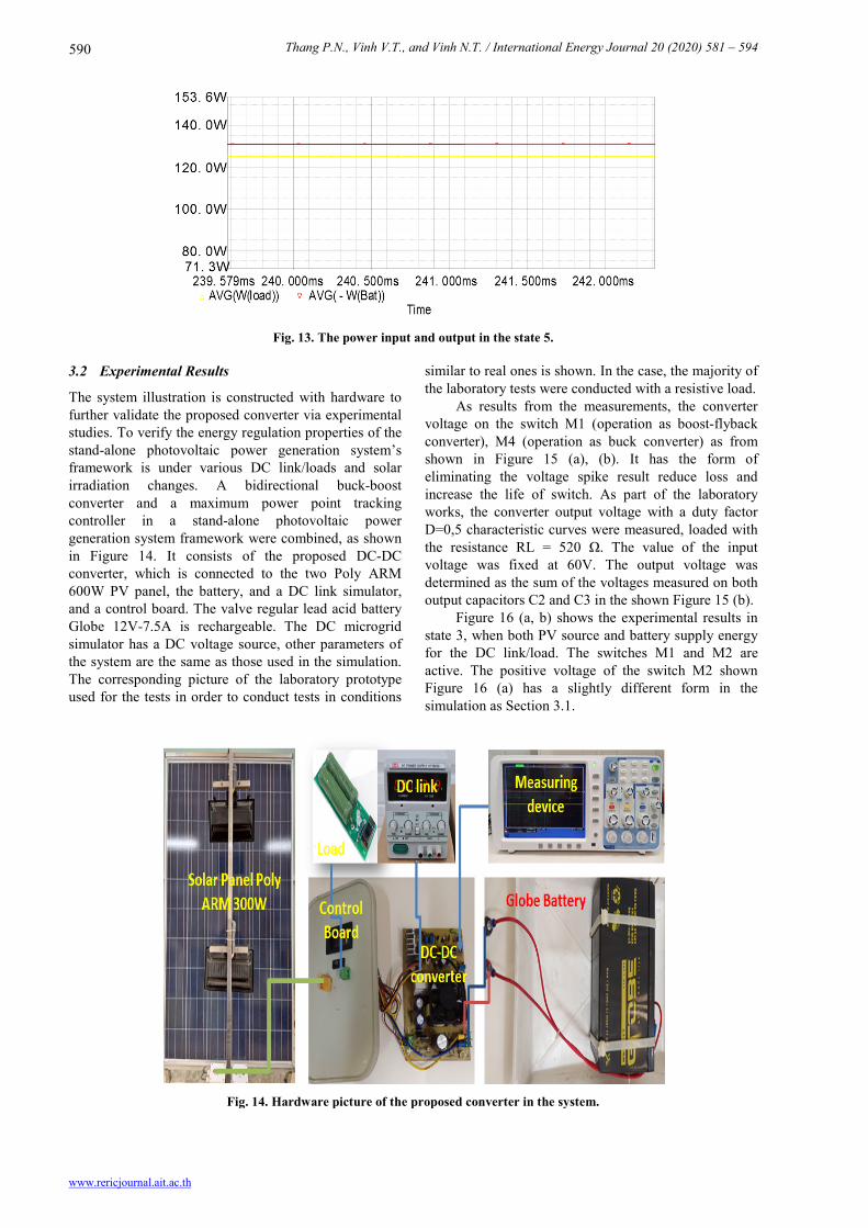
Figure 11 shows operation state 2 of the converter. Figure 11 (a) describes the voltage on pin (Drain) of the M1 and pin (Source) of the M4 (in the principle diagram of the pin (Source) M4 connected to the pin (Drain) M2). The time controlled M4 dependent the one which the time charge/discharge capacitor C1. This time is short, lead to the energy charging for the battery is quite small. Figure 11 (b) illustrates the power of the PV, battery and the DC link/load. Figure 12 illustrate simulation results of the state 3. Figure 12 (a) shows voltage on pin (Drain) of M1 and pin (Drain) of M2, in this converter proposed voltage stress of M3 is large, this is also a limitation of this converter diagram. The power of the PV source, battery and DC link/load are shown in the Figure 12 (b). The simulation results of the state 4 same the state 2 and the state 5 same the state 3. Figure 13 illustrated power of the DC link/load (output) and the battery (input).The simulation results of the presented converter indicate that the converter is able to operate in different conditions. The results are inconsistent with the analysis done in the previous sections. Also, the presented control strategy can control and regulate voltage of DC link.

Thang P.N., Vinh V.T., and Vinh N.T. / International Energy Journal 20 (2020) 581 – 594
www.rericjournal.ait.ac.th
588
(a)
(b)
(c)
Fig. 10. The waveforms of operation state 1, (a) Voltage on the M1, (b) Voltage on the capacitor C1 and DC link/load, (c) The power of battery, PV source and DC link/load.

Thang P.N., Vinh V.T., and Vinh N.T. / International Energy Journal 20 (2020) 581 – 594
www.rericjournal.ait.ac.th
589
(a)
(b)
Fig. 11. Results of the state 2, (a) Voltage on the M1 and M4, (b) Power of battery, PV source and DC link/load.
(a)
(b)
Fig. 12. Waveforms of operation state 3, (a) Voltage on the M1 and M2, (b) Power of load, battery and PV.
Thang P.N., Vinh V.T., and Vinh N.T. / International Energy Journal 20 (2020) 581 – 594
www.rericjournal.ait.ac.th
590
Fig. 13. The power input and output in the state 5.
3.2 Experimental Results
The system illustration is constructed with hardware to further validate the proposed converter via experimental studies. To verify the energy regulation properties of the stand-alone photovoltaic power generation system’s framework is under various DC link/loads and solar irradiation changes. A bidirectional buck-boost converter and a maximum power point tracking controller in a stand-alone photovoltaic power generation system framework were combined, as shown in Figure 14. It consists of the proposed DC-DC converter, which is connected to the two Poly ARM 600W PV panel, the battery, and a DC link simulator, and a control board. The valve regular lead acid battery Globe 12V-7.5A is rechargeable. The DC microgrid simulator has a DC voltage source, other parameters of the system are the same as those used in the simulation. The corresponding picture of the laboratory prototype used for the tests in order to conduct tests in conditions
similar to real ones is shown. In the case, the majority of the laboratory tests were conducted with a resistive load. As results from the measurements, the converter voltage on the switch M1 (operation as boost-flyback converter), M4 (operation as buck converter) as from shown in Figure 15 (a), (b). It has the form of eliminating the voltage spike result reduce loss and increase the life of switch. As part of the laboratory works, the converter output voltage with a duty factor D=0,5 characteristic curves were measured, loaded with the resistance RL = 520 Ω. The value of the input voltage was fixed at 60V. The output voltage was determined as the sum of the voltages measured on both output capacitors C2 and C3 in the shown Figure 15 (b). Figure 16 (a, b) shows the experimental results in state 3, when both PV source and battery supply energy for the DC link/load. The switches M1 and M2 are active. The positive voltage of the switch M2 shown Figure 16 (a) has a slightly different form in the simulation as Section 3.1.
Fig. 14. Hardware picture of the proposed converter in the system.

Thang P.N., Vinh V.T., and Vinh N.T. / International Energy Journal 20 (2020) 581 – 594
www.rericjournal.ait.ac.th
591
(a)
(b)
Fig. 15. Experimental results in state 2 of the boost-flyback and buck mode, (a) The steady-state voltage on the switch M1, (b) The voltage output load resistance.
(a)
(b)
Fig. 16. The wave voltage on switchs, (a) M1, (b) M2 of the operation state 3.

Thang P.N., Vinh V.T., and Vinh N.T. / International Energy Journal 20 (2020) 581 – 594
www.rericjournal.ait.ac.th
592
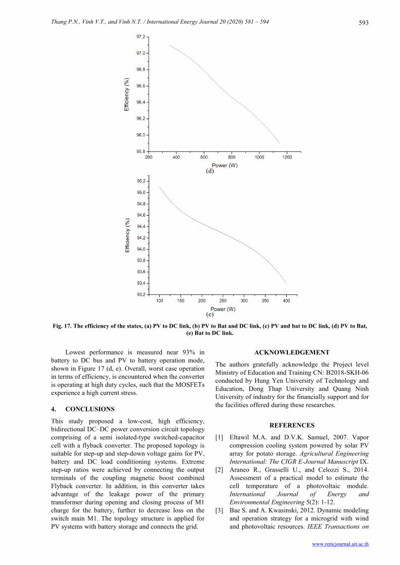
The conversion efficiency of the converter is determined by measuring input/output voltage and current using an oscilloscope. The input voltage is provided by a programmable power supply (Regatron) and the output power is dissipated in pure resistive loads. The efficiency has been measured under all operation modes for different power levels and PV voltage levels. The results are presented in Figure 17 (a,
b, c). The efficiency is measured in the case PV source to battery with a voltage level of PV maximum and when the power increases gradually, the efficiency decreases. The results shown that the proposed converter achieves a maximum efficiency of 98% when the converter operates in scenarios where energy is transmitted from PV to the battery and link DC/load.
(a)
(b)
(c)
Thang P.N., Vinh V.T., and Vinh N.T. / International Energy Journal 20 (2020) 581 – 594
www.rericjournal.ait.ac.th
593
(d)
(e)
Fig. 17. The efficiency of the states, (a) PV to DC link, (b) PV to Bat and DC link, (c) PV and bat to DC link, (d) PV to Bat, (e) Bat to DC link.
Lowest performance is measured near 93% in battery to DC bus and PV to battery operation mode, shown in Figure 17 (d, e). Overall, worst case operation in terms of efficiency, is encountered when the converter is operating at high duty cycles, such that the MOSFETs experience a high current stress.
4. CONCLUSIONS
This study proposed a low-cost, high efficiency, bidirectional DC–DC power conversion circuit topology comprising of a semi isolated-type switched-capacitor cell with a flyback converter. The proposed topology is suitable for step-up and step-down voltage gains for PV, battery and DC load conditioning systems. Extreme step-up ratios were achieved by connecting the output terminals of the coupling magnetic boost combined Flyback converter. In addition, in this converter takes advantage of the leakage power of the primary transformer during opening and closing process of M1 charge for the battery, further to decrease loss on the switch main M1. The topology structure is applied for PV systems with battery storage and connects the grid.
ACKNOWLEDGEMENT
The authors gratefully acknowledge the Project level Ministry of Education and Training CN: B2018-SKH-06 conducted by Hung Yen University of Technology and Education, Dong Thap University and Quang Ninh University of industry for the financially support and for the facilities offered during these researches.
REFERENCES
[1] Eltawil M.A. and D.V.K. Samuel, 2007. Vapor compression cooling system powered by solar PV array for potato storage. Agricultural Engineering International: The CIGR E-Journal Manuscript IX.
[2] Araneo R., Grasselli U., and Celozzi S., 2014. Assessment of a practical model to estimate the cell temperature of a photovoltaic module. International Journal of Energy and Environmental Engineering 5(2): 1-12.
[3] Bae S. and A. Kwasinski, 2012. Dynamic modeling and operation strategy for a microgrid with wind and photovoltaic resources. IEEE Transactions on

Thang P.N., Vinh V.T., and Vinh N.T. / International Energy Journal 20 (2020) 581 – 594
www.rericjournal.ait.ac.th
594
Smart Grid 3(4): 1867-1876. [4] Qian Z., Abdel-Rahman O., and Batarseh I., July
2010. An integrated four-port dc/dc converter for renewable energy application. IEEE Transactions on Power Electronics 25(7): 1877-1887.
[5] Zeng J., Qiao W., Qu L., and Jiao Y., 2014. An isolated multiport DC-DC converter for simultaneous power management of multiple different renewable energy sources. IEEE J. Emerging Sel. Topics Power Electron 2(1): 70-78.
[6] Gummi K. and M. Ferdowsi., 2010. Double-input DC–DC power electronic converters for electric-drive vehicles topology exploration and synthesis using a single-pole triple-throw switch. IEEE Trans. Ind. Electron 57(2): 617-623.
[7] Bayindir R., Colak I., Fulli G., and Demirtas K., December 2016. Smart grid technologies and applications. Renewable and Sustainable Energy Reviews 66: 499-516.
[8] Al-Hamad M., 2005. Maximum Power Transfer from Photovoltaic Power Cell to Drive Three Phases Induction Motors. Master thesis. University of Bahrain.
[9] Ghodke D., Chatterjee K., and Fernandes B., 2013. Modified soft-switched three-phase three level dc dc converter for high-power applications having extended duty cycle range. IEEE Transactions Industrial Electronics 59: 3362–3372.
[10] Pahlevaninezhad M., Drobnik J., Jain P., and Bakhshai A., 2012. A load adaptive control approach for a zero-voltage-switching dc/dc converter used for electric vehicles. Industrial Electronics, IEEE Transactions 59: 920–933.
[11] Zeng J., Qiao W., and Qu L., December 2013. An isolated three-port bidirectional DC-DC converter for Photovoltaic systems with energy storage. Industry Applications Society Annual Meeting (IAS), Conference Record of the IEEE: 1-8.
[12] Suetomi M., Imamichi D., Matsumoto S., Ueda D., Yang J.R., Ishizuka Y., Lin W.G., and Matsuo H., 2011. A novel bidirectional DC-DC converter with high power efficiency for isolation in high voltage DC power feeding systems. In Proceedings of IEEE 33rd International Telecommunications Energy Conference: 1-4.
[13] Kumar M., Singh S.N., and Srivastava S.C., 2012. Design and control of smart DC microgrid for integration of renewable energy sources. In Proceedings of IEEE Power and Energy Society General Meeting: 1-7.
[14] Edelmoser K.H., and F.A. Himmelstoss, 2004.
Bidirectional DC-to-DC converter for solar battery backup applications. In Proceedings of IEEE 35th Annual Power Electronics Specialists Conference: 2070-2074.
[15] Zhao B., Yu Q., and Sun W., November 2012. Extended phase shift control of isolated bidrectional dc-dc converter for power distribution in microgrid. Power Electronics, IEEE Transactions 27(11): 4667-4680.
[16] dos Santos E., 2013. Dual-output dc-dc buck converters with bidirectional and unidirectional characteristics. Power Electronics, IET 6: 999–1009.
[17] Vinh N.T, Pierre P., Michel A., Chafic S., Jean-Pierre C., 2015. Efficiency of magnetic coupled boost DC-DC converters mainly dedicated to renewable energy systems: Influence of the coupling factor. International Journal of Circuit Theory and Applications 43(8): 1042–1062.
[18] Petit P., Aillerie M., Vinh Nguyen T., Jean-Pierre C., 2014. Basic MOSFET based vs. couple-coils boost converters for photovoltaic generators. International Journal of Power Electronics and Drive Systems 4(1): 1-11.
[19] Thai Giang V., Vinh Nguyen T., Vinh Vo T., 2018. Highly Efficient step-up Boost-Flyback coupled magnetic integrated converter for photovoltaic energy. International Journal of Circuit and Electronics 3: 14-18.
[20] Lee S., Kim P., and Choi S., 2013. High step-up soft-switched converters using voltage multiplier cells. IEEE Trans. Power Electron 28(7): 3379-3387.
[21] Rodriguez G., Andres L., and Balda J.C., 2013. A comparison of isolated DC-DC converters for microinverter applications. Power Electronics Conference and Exposition (APEC), 2013 Twenty-Eighth Annual IEEE.
[22] Hsieh, Y.P., Chen, J.F., Liang, T.J., Yang, L.S., 2011. Novel high step-up DC-DC converter with coupled-inductor and switched-capacitor techniques for a sustainable energy system. IEEE Trans. Power Electron 26: 3481–349.
[23] Changchien S.K., Liang T.J., Chen J.F., Yang L.S., 2013. Step-up DC-DC converter by coupled inductor and voltage-lift technique. IET Power Electron 3: 369–378.
[24] Kawa A., Penczez A., Piróg S., 2014. DC-DC boost-flyback converter functioning as input stage for one phase low power grid-connected inverter. Archives of Electrical Engineering 63(3): 393-407.