a flying gripper based on cuboid modular robotsdas819/pdf/icra18-modquad-gripper.pdfthe propellers...
TRANSCRIPT

A Flying Gripper Based on Cuboid Modular Robots
Bruno Gabrich1∗, David Saldana1∗, Vijay Kumar1, and Mark Yim1.
Abstract— We present a novel flying modular platform ca-pable of grasping and transporting objects. It is composed offour cooperative identical modules where each is based on aquadrotor within a cuboid frame with a docking mechanism.Pairs of modules are able to fly independently and physicallyconnect by matching their vertical edges forming a hinge. Fourone degree of freedom (DOF) connections results in a one DOFfour-bar linkage that can be used to grasp external objects. Inthis paper, we propose a decentralized method that allows theFlying Gripper to control its position, attitude and apertureangle. In our experiments, we tested the hovering performancefor different aperture angles and with a grasped object. Theperformance for a closing and opening motion was also verified.
I. INTRODUCTION
In nature, cooperative work allows small insects to manip-ulate and transport objects often heavier than the individuals.Unlike collaboration on the ground, collaboration in airis more complex because of flight stability. Manipulationusing a single flying robot with a serial arm manipulatorattached to its body [1], [2], [3], is of growing interest inthe robotics research community. However, the attachmentof an external mechanism on the aerial vehicle increases thesystem complexity [4], changing inertia, center of mass andoverall weight [5]. In order to avoid these issues, relatedapproaches consider the use of light-weight grippers [6],[7], [8]. Those systems minimize the degrees of freedom(DOF) in order to reduce the system complexity, although,these solutions do not avoid the attachment requirement ofan external active mechanism. A recent work considers anovel approach for grasping objects in flight [9], [10]. Thispaper presents a novel modular aerial platform in whichmultiple single propelled modules, when attached together,cooperatively form a flying vehicle capable of seizing andgrasping objects. The grasping action relies on the actuationof the revolute joints located at each module.
The lift capability of modular quadrotors can be increasedthrough the manual docking of other modules to the originalmodular configuration [11]. Collaborative manipulation inair is an alternative to reduce the complexity of addingmanipulator arms to flying vehicles. Multiple quadrotors,with light-weight grippers, cooperatively work to carry pay-loads of different geometries and weights [12]. Although,
* Equal contributors.1 B. Gabrich, D. Saldana, V. Kumar and M. Yim are with the
GRASP Laboratory, University of Pennsylvania, Philadelphia, PA, USA:brunot, dsaldana, kumar, [email protected].
The authors gratefully acknowledge the support of the Brazilian agencyCAPES. The support of DARPA grant HR00111520020, ONR grantsN00014-15-1-2115 and N00014-14-1-0510, ARL grant W911NF-08-2-0004, NSF grant IIS-1426840, NSF grant 1138847, and TerraSwarm, oneof six centers of STARnet, a Semiconductor Research Corporation programsponsored by MARCO and DARPA.
Fig. 1. The Flying Gripper holding a coffee cup in midair.
the transporting capability is only guaranteed through theattachment of extra mechanisms and parts.
In a previous work [13], we studied fast self-assemblyalgorithms for cuboid modules with rigid connections (faceto face). In this work, we study non-rigid connections (edge-to-edge) in midair. This type of connection allows the robotsto cooperatively grasp objects, as it can be seen in Fig.1. Here, four modular flying robots are connected togetheredge-to-edge with cylindrical magnets. The modules bodyform links in a four-bar linkage that are able to constrain anobject in flight by actuating in a cooperative manner. Unlikeprevious works, we avoid the addition of extra componentsand embed the grasping capability to the flying vehicleitself, in which the gripper opening-closing motion relies onthe propellers actuation only. The main advantage of thisplatform is its modular capability. Four quadrotors togethercan deliver a grasping capability without adding any activemechanism.
The contributions of this paper are twofold. i) We presentthe design and the dynamical model of a novel modularflying gripper. ii) We propose a decentralized method tocontrol the attitude and aperture of the Flying Gripper.
II. DESIGN AND MECHANICAL SYSTEM
In the literature, cages for quadrotors are used to enablecollision-safe navigation [14]. In our work, we use a light-weight cage to enclose a quadrotor (see Fig. 2). This cageneeds to be resilient and light-weight. Docking capabilitieswere also added to the mechanical system allowing multiplecages to be connected through the use of permanent magnets[15], [16].
A. Flying VehicleIn the proposed modular platform we use the Crazyflie 2.0
as the chosen aerial vehicle due to its size and ease in

carbon
quadrotor
cylindrical
3-D printed
magnets
connectorfiber rod
tiltedrotor
Fig. 2. A Flying Modular Robot. Equipped with cylindrical magnets locatedat the corner of the carbon fiber cages. This docking mechanism allows aone DOF connection between two modules.
making adaptations. The quadrotor itself weights 27g andits dimensions are 92x92x29mm. Its battery life lasts aroundseven minutes, though in our case battery life time is reduceddue to the extra payload. The platform is open-source andopen-hardware. The motor mounting was modified from thestandard design, we tilted the rotors α = 15. This wasnecessary as more yaw authority was required to enablegrasping as a four-bar. However, adding this tilt reduces thequadrotor lifting thrust by 3% [17].
The light-weight cages are made of carbon fiber rods with3-D printed connectors made of ABS. The connectors arelocated at the corners of the cage to form the cuboid shape.The cage weights 8g.
B. Docking mechanism
Axially magnetized cylindrical Neodymium Iron Boron(NdFeB) magnets, with 1/8′′ of diameter and 1/4′′ ofthickness are mounted on each corner enabling edge-to-edge connections. The cylindrical magnets have mass 0.377gand are able to generate a force of 0.4 kg in a tangentialconnection between two of the same magnets. This forms astrong bond when two modules connect in flight. Note thatthe connections are not rigid - each forms a one DOF hinge.
C. System Motion
The four attached modules results in a one DOF four-barlinkage in addition to the combined position and attitudeof the conglomerate (see Fig. 3). The four-bar internalangles are controlled by the yaw attitude ψi of each moduleillustrated in Fig. 3. For example modules 1 and 3 rotateclockwise and robots 2 and 4 rotate counter-clockwise in acoordinated manner.
III. FLYING GRIPPER MODEL
We formulate our flying mechanism based on two maincomponents defined as follows.
Definition 1 (Module). A module is a flying robot that canmove by itself in a three dimensional environment and dockhorizontally to other modules by matching the vertical edges.
Definition 2 (Flying Gripper). A flying gripper is composedof four modules connected as a rotational joint at an edge.
Fig. 3. Flying Gripper motion in a closing procedure; the most left pictureshows a 90of aperture; the center picture shows a 64of aperture; the mostright picture shows a 22of aperture.
The four connected modules form a four-bar linkage witha inner area as a rhombus shape where the angles of therhombus can be modified by changing the yaw orientationof the modules.
We consider a group of four modules, indexed by i =1, ..., 4. All modules are homogeneous meaning they have thesame shape, inertia, mass and actuators. The location of theith module relative to the Flying Gripper coordinate frameG is denoted by rGi ∈ R3. The position of the actuator j ofthe module i written in the module coordinate frame Mi isdenoted as aMi
ij = [xMiij , yMi
ij , zMiij ]> or as aGij ∈ R3 written
in the Flying Gripper coordinate frame G. The attitude ofthe modules are defined by the Euler Angles in which φi isroll, θi is pitch and ψi denotes the yaw angle for module i.The inertia tensor of each individual module is defined by I.Along the same lines, the Flying Gripper attitude is definedby φG, θG, ψG and its aperture angle by γ ∈ [0, π] (seeFig. 4). The Flying Gripper moment of inertia is defined asJ.
Our modules are based on a quadrotor platform whichhas four rotors in a square configuration. Each module iis equipped with four rotors, indexed by j = 1, ..., 4, thatproduce angular speeds ωij to generate vertical forces
fij = Kf cos(α)ω2ij ,
and moments
Mij = ±(Kf sin(α)d+Km cos(α))ω2ij ,
where Kf and Km are motor constants that can be obtainedexperimentally, d is the distance from the motor j to themodule i center of mass, and α is the inclination of the rotor(see the tilted rotors in Fig. 2). Each rotor j from module iis rotated around the vector aMi
ij . Therefore we can rewritethe forces as
fij = kfω2ij ,
and momentsMij = ±kmω2
ij ,
where kf = Kf cos(α) and km = Kf sin(α)d+Km cos(α).The moments are dependent on the direction the propellersspin, which is clockwise or counterclockwise, and on thedirection the propellers are tilted. Therefore, propellers 1 and3 are rotated in a positive direction around its correspondentvector aMi
ij , while propellers 2 and 4 are rotated in a negativedirection.

θG pitch
φG roll
ψG yaw
f11
f14 f12
f13
f31
f34 f32
f33
f24
f23 f21
f22
f44
f43 f41
f42
βi
Fig. 4. Representation of the Flying Gripper – the four modules with theirrespective framesMi oriented relative to the Flying Gripper frame G. TheFlying Gripper angles are φG, θG, ψG , where φG is the rotation aroundthe x-axis in G, θG is the rotation around the y-axis in G and ψG is therotation around the z− axis in G. The positions of the forces fij are alsoillustrated as well as the directions that each propeller spins.
IV. FLYING GRIPPER DYNAMICS
The Flying Gripper configuration is a specific moduleformation that enables the opening and closing motion. Thevariation in the yaw angle of the modules directly changesthe aperture angle γ. The total force and moments, can bewritten in terms of the actuator forces of each individualmodule in a similar form as the single quadrotor case. Basedon the actuator forces, we can write the linear accelerationsas
4mrG =
00
−4mg
+ RWG
00∑ij fij
,where RWG is the rotation from the world coordinateframeW to the Flying Gripper frame G. This transformationis represented by the ZXY Euler angles, where 4 is the totalnumber of modules, m is the mass of each individual moduleand g is the acceleration of gravity. The rotation from theworld coordinate frame W to the Flying Gripper frame G isdefined as
RWG =
cψcθ − sφsψsθ −cφsψ cψsθ + cθsφsψcθsψ + cψsφsθ cφcψ sψsθ − cψcθsφ−cφsθ sφ cφcθ
where cθ = cos θ, sθ = sin θ. Similarly for the angles φ andψ.
The aperture angle γ can be derived based on geometry.Fig. 4 shows a rhombus shape formed in the empty spacebetween modules. Since the shape can be divided into twoisosceles triangles, we can write γ in terms of ψGi as
γ = 2(−1)i+1ψGi . (1)
Considering the yaw attitude for all modules and its second
derivative, we can write the angular acceleration for γ as:
γ =1
2
4∑i=1
(−1)i+iψGi .
The linearized rotational dynamics in terms of the angularaccelerations is given by
J[φG, θG, ψG, γ
]>=[MxG,MyG,MzG, T
]>,
where [MxG,MyG,MzG]> are the Flying Gripper moments
and T its closing and opening torque. Due to the additionof an extra DOF the rotational dynamics presents differentdimensions compared to the conventional quadrotor dynam-ics. The matrix J ∈ R4×4 is the Flying Gripper inertia andis defined as follows
J =
[IG 00> 2Iz
]where Iz is the inertia around the z-axis for an individualmodule i. The tensor IG ∈ R3×3 is the Flying Gripper inertiafor roll, pitch and yaw. It can be obtained by
IG =
4∑i=1
Ii, (2)
where Ii is the contribution of inertia from each module i tothe system as a whole. Ii ∈ R3×3 can be computed throughthe parallel axis theorem and reorienting the inertia of theith module according to the frame G. Thus, we can write itas
Ii = RGMiIRMi
G +m
r2yi 0 00 r2xi 0
0 0 (rxi + ryi)2
, (3)
where I ∈ R3×3 is the inertia tensor of the ith module,rxi and ryi are the components of the position vector ri =
[rxi , ryi , rzi ]>, and RGMi
∈ R3×3 is the rotation matrix fromframe G to frameMi. Assuming the modules are symmetric,this inertia tensor can be written as I = Diag([Ix, Iy, Iz]).Therotation matrix can be defined as follows
RGMi=
cos γ2 (−1)i+1 − sin γ2 (−1)
i+1 0sin γ
2 (−1)i+1 cos γ2 (−1)
i+1 00 0 1
(4)
Then, from (2) and (3) we can compute the Flying Grippermoment of inertia in the x,y,z axis:
IG = 2(Rz, γ2
IR>z, γ2+ R>z, γ2
IRz, γ2
)+
m∑i
r2yi 0 00 r2xi 0
0 0 (rxi + ryi)2
.The rotation matrix Rz, γ2
∈ R3×3 is a specific case of RGMi.
The inertia considers the position rGi of each module relativeto the Flying Gripper frame G, as well as the transformationRGMi
for each module i relative to G.Note that the Flying Gripper moments
[MxG,MyG,MzG, T]> and total force FG can be derived

from the forces fij produced by each rotor j of the ithmodule. Then, we can describe the resultant moments andtotal force as
FGMxG
MyG
MzG
T
=∑i
1 1 1 1
−yGij −yGij −yGij −yGijxGij xGij xGij xGijkmkf
−kmkfkmkf
−kmkf−pi pi −pi pi
fi1fi2fi3fi4
,where pi = (−1)ikm/kf . The positions of the actuatorsaGij = [xGij , y
Gij , z
Gij ]> are dependent on the aperture angle γ.
Given aMiij = [xMi
ij , yMiij , zMi
ij ]>, which is fixed, we applya transformation to obtain aGij
aGij =[RGMi
rGi] [aMi
ij
1
],
where rGi is each module i position vector in the FlyingGripper frame G. It can be written as
rGi =w√2
2
√2 sin
(π+(i−1)2π
4
)√1− cos γ + cosβi(γ)
sinβi(γ)0
,where w is the module width, and βi(γ) ∈[π4 (−1)
i+1, π2 (−1)i+1] for i = 1, 2 and βi(γ) ∈
[π2 (−1)i, 3π4 (−1)i] for i = 3, 4 (illustrated in Fig. 4).
It can be computed as follows
βi(γ) =π
4
(2 cos i
π
2+ cos iπ + 2 sin i
π
2+ sin iπ
)+γ
2(−1)i+1
In this work one of the objectives is to describe the controlof the input commands sent to each one of the motors fij .Hence, the following section describes our proposed methodto control the Flying Gripper attitude and aperture.
V. FLYING GRIPPER CONTROL
The Flying Gripper Control is divided in three stages.Initially we present a centralized trajectory controller thatgenerates a Flying Gripper attitude. Afterwards, we describethe procedure to decentralize the attitude controller to allmodules and how the angular accelerations are computed.Later we derive a transformation to generate the controlinputs for the j rotor of the module i.
A. Centralized Trajectory Control
The centralized trajectory controller is based in a non-linear controller [18] and assumes the extra degree offreedom γ. Given a desired trajectory in the world framer∗G = [xG, yG, zG]
> and desired linear velocities r∗G =[xG, yG, zG]
> we apply a proportional-derivative controllerwith a feed-forward term rG = [xG, yG, zG]
> to obtain thedesired linear accelerations in the world frame r∗G
r∗G = rG + Kp(r∗G − rG) + Kd(r
∗G − rG),
where Kp is the proportional matrix gains represented asDiag([Kp,x,Kp,y,Kp,z]) and the derivative matrix gains isrepresented by Kd = Diag([Kd,x,Kd,y,Kd,z]). Given the
linear accelerations r∗G we can compute the desired attitudeΘ∗G = [φ∗G, θ
∗G, ψ
∗G]> and desired aperture γ∗, where ∆∗ =
[Θ∗G, γ∗]>, and FG is the total Flying Gripper force
[FG
∆∗
]=
4m 0 0 0 00 1
gsinψG − 1
gcosψG 0 0
0 1gcosψG
1gsinψG 0 0
0 0 0 1 00 0 0 0 1
z∗Gx∗Gy∗Gψ∗Gγ∗
+
4mg0000
where ψG is the actual yaw attitude for the Flying Gripper.A centralized behavior [FG,∆
∗]> is generated and now itneeds to be distributed to all modules.
B. Decentralized Attitude and Aperture Control
In this section, a decentralized attitude and aperture controlfor the Flying Gripper is described. Initially, the modulesreceive the desired attitude and aperture ∆∗ = [Θ∗G, γ
∗]>
from the centralized trajectory controller. Thus, given adesired ∆∗, we can apply a transformation to compute thedesired attitude for the ith module Θ∗i . This distribution forthe desired attitude can be obtained by
Θ∗i = Di∆∗, (5)
where Di ∈ R3×4 is the distribution matrix that can beobtained based on the orientation of the ith module relativeto G. From (4) and (1), we write the distribution matrix Di
as
Di =
cos γ2 (−1)i+1 sin γ
2 (−1)i+1 0 0
− sin γ2 (−1)
i+1 cos γ2 (−1)i+1 0 0
0 0 1 (−1)2
i+1
.This desired attitude Θ∗i for each individual module canbe obtained in a decentralized manner. Each module canalso use a proportional-derivative controller to compute theangular accelerations
φi = Kp,φ(φ∗i − φi) +Kd,φ(φ
∗i − φi)
θi = Kp,θ(θ∗i − θi) +Kd,θ(θ
∗i − θi)
ψi = Kp,ψ(ψ∗i − ψi) +Kd,ψ(ψ
∗i − ψi)
where Kp,Kd are constant positive gains. We can rewritethis proportional-derivative controller in a compact form
ΩMii = Kp,Θ(Θ∗i −Θi) + Kd,Ω(Ω∗i −Ωi) (6)
where ΩMii is the desired angular acceleration of the ith
module in its coordinate frame Mi. The diagonal ma-trices Kp,Θ = Diag([Kp,φ,Kp,θ,Kp,ψ]) and Kd,Ω =Diag([Kd,φ,Kd,θ,Kd,ψ]) contains the proportional andderivative gains constants respectively. The desired angularvelocity can either come from the trajectory or be equal tozero Ω∗i = 0.
Given a desired Flying Gripper attitude and aperture ∆∗,we are able to obtain each module angular acceleration ΩMi
i .Those accelerations are calculated in each module frame,although each module needs to compute the control inputsfor their motors based on the Flying Gripper frame G. Wethen apply the following transformation
ΩGi = RGMiΩMi , (7)
Module 1
Ω1, Ω1
Eq.(5)
IMU 1
Robot 1
Gripper
Eq.(7)
Eq.(6)
Eq.(8)
Eq.(11)
...Sensor γ
γ γ
ΩMii MGΘ∗i ΩGi ui
Module 4
Ω4, Ω4
Eq.(5)
IMU 4
Robot 4Eq.(7)
Eq.(6)
Eq.(8)
Eq.(11)
γ γ
ΩMii MGΘ∗i ΩGi ui
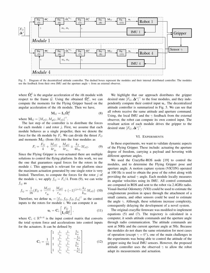
Fig. 5. Diagram of the decentralized attitude controller. The dashed boxes represent the modules and their internal distributed controller. The modulesuse the feedback from their own IMU and the aperture angle γ from an external observer.
where ΩGi is the angular acceleration of the ith module withrespect to the frame G. Using the obtained ΩGi , we cancompute the moments for the Flying Gripper based on theangular acceleration of the ith module. Then we have,
MG = IGΩGi (8)
where MG = [MxG,MyG,MzG]>.
The last step of the controller is to distribute the forcesfor each module i and rotor j. First, we assume that eachmodule behaves as a single propeller, then we denote theforce for the ith module by Fi. We can divide the thrust FGand moments MG (from (8)) into the four modules as
Fi =FG4
+MxG
4ryi+MyG
4rxi± kf
4kmMzG. (9)
Since the Flying Gripper is over-actuated there are multiplesolutions to control the flying platform. In this work, we usethe one that guarantees equal forces for the rotors in themodule i. This approach is relevant for our platform sincethe maximum actuation generated by one single rotor is verylimited. Therefore, to compute the forces for the rotor j ofthe module i, we apply fij = Fi/4. From (9), we can writefij as
fij =1
16(FG +
MxG
ryi+MyG
rxi+ (−1)(j+1) kf
kmMzG) (10)
Therefore, we define ui = [fi1, fi2, fi3, fi4]> as the control
inputs to the rotors for module i. We can compute it as
ui = Ci
[FG
IGΩGi
], (11)
where Ci ∈ R4×4 is the input control matrix that convertsthe total system force and accelerations into control inputsfor the actuators. It can be defined by
Ci =1
16
1 1
ryi
1rxi
kfkm
1 1ryi
1rxi
− kfkm
1 1ryi
1rxi
kfkm
1 1ryi
1rxi
− kfkm
. (12)
We highlight that our approach distributes the gripperdesired state [FG,∆
∗]> to the four modules, and they inde-pendently compute their control input ui. The decentralizedattitude controller is summarized in Fig. 5. We can see thatall robots receive the same attitude and aperture command.Using, the local IMU and the γ feedback from the externalobserver, the robot can compute its own control input. Theresultant action of each module drives the gripper to thedesired state [FG,∆
∗]>.
VI. EXPERIMENTS
In these experiments, we want to validate dynamic aspectsof the Flying Gripper. These include: actuating the aperturedegree of freedom, carrying a payload and hovering withdifferent aperture angles.
We used the Crazyflie-ROS node [19] to control themodules, and to determine the Flying Gripper pose andaperture angle. A motion capture system (VICON) operatedat 100 Hz is used to obtain the pose of the robot along withproviding the actual γ angle. Each module locally measuresits angular velocities using its IMU. All control commandsare computed in ROS and sent to the robot via 2.4GHz radio.Visual-Inertial Odometry (VIO) could be used to estimate theconglomerate position in space through the attachment of asmall camera, and other sensors could be used to estimatethe angle γ. Although, these solutions increase complexity,consequently delaying the development of a novel system.
The original crazyflie firmware was modified to implementequations (5) and (7). The trajectory is calculated in acomputer, it sends attitude commands and the aperture anglethrough radio communication. The attitude commands aresent at 50Hz and the current aperture angle at 5Hz. Becausethe modules do not share the same orientation for most casesof operation (except γ = 0), one of the main challenges inthe experiments was being able to control the attitude of thegripper using the local IMU sensors. However, the proposedattitude controller uses the observed γ to allow the robotadapt its measurements and actuation.

0 5 10 15 20 25 30
time (s)
0
10
20
30
40
50
60
70
80
90
γ(deg
)
γ = 0
γ = 30
γ = 60
γ = 90
Fig. 6. Hovering with different aperture angles.
0 5 10 15 20 25
time (s)
0.65
0.70
0.75
0.80
z(m
)
payload= 14.30 gpayload= 0.00 g
Fig. 7. Hovering with and without a coffee cup.
A. Hovering for specific γ apertures
Initially we want to evaluate the behavior of the FlyingGripper for a hover condition. The robots try to maintaina given aperture angle γ during flight. The Flying Gripperhovers at z = 0.65m from the ground.
In Fig. 6, we can see the gripper maintains various initialaperture angles over time open-loop. The only exceptionis the case of 90, where the aperture drifts from 90 to71. Sometimes we notice a heterogeneous behavior duringtakeoff, where we see some modules taking off a couple ofmilliseconds before or after an adjacent module. Wheneverit happens, each module attitude controller tries to correctand stabilize in different proportions. Consequently, reactionforces acts on the flying vehicle causing, for specific cases,an angle drift for the open-loop case.
B. Hovering with and without a payload
The Flying Gripper behavior under an additional payloadis verified with the gripper constraining a simple cup. Fig. 7illustrates both cases with and without payload and theimpact on altitude. We can see the extra load generates higheroscillations in the z-axis in comparison to the no-payloadcase. The bigger amplitudes for the payload case is justifiablesince the hovering controller is trying to compensate for theextra weight, but overshoots.
0 5 10 15 20 25 30 35 40 45
time (s)
20
30
40
50
60
70
80
90
100
ψi(deg
)
ψ1
ψ2
ψ3
ψ4
0
10
20
30
40
50
60
70
γ(deg
)
γ
Fig. 8. Closing the gripper. The plot shows the change of the yaw angle ofthe modules (continuous lines) while the aperture angle is reducing (dashedline).
C. Gripper actuation
The aperture angle γ is controlled in midair. The gripper isbeing actuated through an aperture angle under closed-loopcontrol. The result of closing the gripper in midair can beseen in Fig. 8. It illustrates how the modules change theiryaw orientation to progressively reduce the aperture of thegripper. We know that all modules have approximately thesame orientation when the gripper is closed. Then, we cansee this exact behavior after second 30, where the robotsachieve the same orientation as the gripper. Although thecontrol of the yaw and the aperture angles are coupled, wecan see that the orientation of the gripper was maintainedas the robots closed the gripper, meaning the aperture anglewas changing towards to 0.
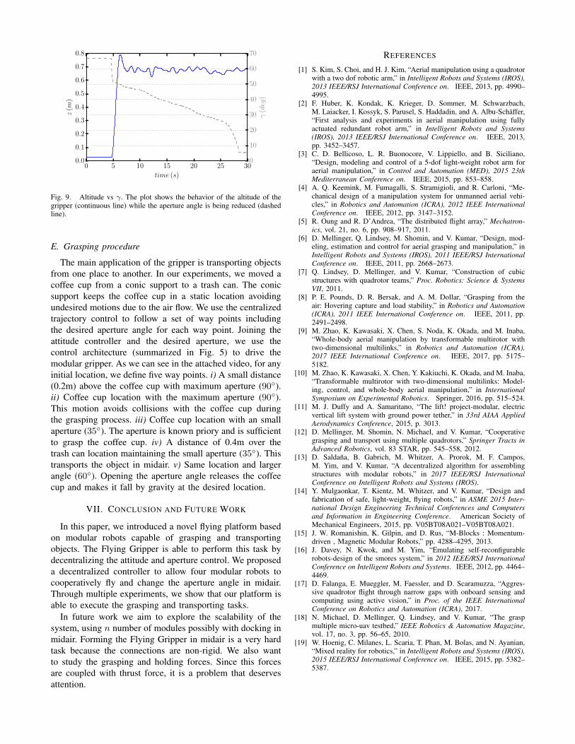
An important capability of the Flying Gripper is beingable to change the aperture angle without compromisingthe stability and at the same time maintaining at a desiredlocation in space. Fig. 9 illustrates how the griper canprogressively close the aperture angle without affecting thealtitude. The aperture angle was actuated from 68 to 0 andthe time-response of this actuation was around 25 seconds.We also notice that the altitude remains approximately con-stant. Therefore, we conclude that the system is capable toaccurately approach an object at a specific height and graspit.
D. Yaw Actuation
The initial experiments were conducted with propellersoriented parallel to the ground during hover. For the Crazyflie2.0, the moments generated to actuate the aperture angleγ by the normal method of differential velocities betweendiagonal propeller pairs were not strong enough. To increasethe controllable yaw moment, we tilted the propellers 15
as in [17]. This created 3 times more yaw-control actionallowing the gripper to generate enough moments to executethe grasping procedure.
0 5 10 15 20 25 30
time (s)
0.0
0.1
0.2
0.3
0.4
0.5
0.6
0.7
0.8
z(m
)
0
10
20
30
40
50
60
70
γ(deg
)
Fig. 9. Altitude vs γ. The plot shows the behavior of the altitude of thegripper (continuous line) while the aperture angle is being reduced (dashedline).
E. Grasping procedure
The main application of the gripper is transporting objectsfrom one place to another. In our experiments, we moved acoffee cup from a conic support to a trash can. The conicsupport keeps the coffee cup in a static location avoidingundesired motions due to the air flow. We use the centralizedtrajectory control to follow a set of way points includingthe desired aperture angle for each way point. Joining theattitude controller and the desired aperture, we use thecontrol architecture (summarized in Fig. 5) to drive themodular gripper. As we can see in the attached video, for anyinitial location, we define five way points. i) A small distance(0.2m) above the coffee cup with maximum aperture (90).ii) Coffee cup location with the maximum aperture (90).This motion avoids collisions with the coffee cup duringthe grasping process. iii) Coffee cup location with an smallaperture (35). The aperture is known priory and is sufficientto grasp the coffee cup. iv) A distance of 0.4m over thetrash can location maintaining the small aperture (35). Thistransports the object in midair. v) Same location and largerangle (60). Opening the aperture angle releases the coffeecup and makes it fall by gravity at the desired location.
VII. CONCLUSION AND FUTURE WORK
In this paper, we introduced a novel flying platform basedon modular robots capable of grasping and transportingobjects. The Flying Gripper is able to perform this task bydecentralizing the attitude and aperture control. We proposeda decentralized controller to allow four modular robots tocooperatively fly and change the aperture angle in midair.Through multiple experiments, we show that our platform isable to execute the grasping and transporting tasks.
In future work we aim to explore the scalability of thesystem, using n number of modules possibly with docking inmidair. Forming the Flying Gripper in midair is a very hardtask because the connections are non-rigid. We also wantto study the grasping and holding forces. Since this forcesare coupled with thrust force, it is a problem that deservesattention.
REFERENCES
[1] S. Kim, S. Choi, and H. J. Kim, “Aerial manipulation using a quadrotorwith a two dof robotic arm,” in Intelligent Robots and Systems (IROS),2013 IEEE/RSJ International Conference on. IEEE, 2013, pp. 4990–4995.
[2] F. Huber, K. Kondak, K. Krieger, D. Sommer, M. Schwarzbach,M. Laiacker, I. Kossyk, S. Parusel, S. Haddadin, and A. Albu-Schaffer,“First analysis and experiments in aerial manipulation using fullyactuated redundant robot arm,” in Intelligent Robots and Systems(IROS), 2013 IEEE/RSJ International Conference on. IEEE, 2013,pp. 3452–3457.
[3] C. D. Bellicoso, L. R. Buonocore, V. Lippiello, and B. Siciliano,“Design, modeling and control of a 5-dof light-weight robot arm foraerial manipulation,” in Control and Automation (MED), 2015 23thMediterranean Conference on. IEEE, 2015, pp. 853–858.
[4] A. Q. Keemink, M. Fumagalli, S. Stramigioli, and R. Carloni, “Me-chanical design of a manipulation system for unmanned aerial vehi-cles,” in Robotics and Automation (ICRA), 2012 IEEE InternationalConference on. IEEE, 2012, pp. 3147–3152.
[5] R. Oung and R. D’Andrea, “The distributed flight array,” Mechatron-ics, vol. 21, no. 6, pp. 908–917, 2011.
[6] D. Mellinger, Q. Lindsey, M. Shomin, and V. Kumar, “Design, mod-eling, estimation and control for aerial grasping and manipulation,” inIntelligent Robots and Systems (IROS), 2011 IEEE/RSJ InternationalConference on. IEEE, 2011, pp. 2668–2673.
[7] Q. Lindsey, D. Mellinger, and V. Kumar, “Construction of cubicstructures with quadrotor teams,” Proc. Robotics: Science & SystemsVII, 2011.
[8] P. E. Pounds, D. R. Bersak, and A. M. Dollar, “Grasping from theair: Hovering capture and load stability,” in Robotics and Automation(ICRA), 2011 IEEE International Conference on. IEEE, 2011, pp.2491–2498.
[9] M. Zhao, K. Kawasaki, X. Chen, S. Noda, K. Okada, and M. Inaba,“Whole-body aerial manipulation by transformable multirotor withtwo-dimensional multilinks,” in Robotics and Automation (ICRA),2017 IEEE International Conference on. IEEE, 2017, pp. 5175–5182.
[10] M. Zhao, K. Kawasaki, X. Chen, Y. Kakiuchi, K. Okada, and M. Inaba,“Transformable multirotor with two-dimensional multilinks: Model-ing, control, and whole-body aerial manipulation,” in InternationalSymposium on Experimental Robotics. Springer, 2016, pp. 515–524.
[11] M. J. Duffy and A. Samaritano, “The lift! project-modular, electricvertical lift system with ground power tether,” in 33rd AIAA AppliedAerodynamics Conference, 2015, p. 3013.
[12] D. Mellinger, M. Shomin, N. Michael, and V. Kumar, “Cooperativegrasping and transport using multiple quadrotors,” Springer Tracts inAdvanced Robotics, vol. 83 STAR, pp. 545–558, 2012.
[13] D. Saldana, B. Gabrich, M. Whitzer, A. Prorok, M. F. Campos,M. Yim, and V. Kumar, “A decentralized algorithm for assemblingstructures with modular robots,” in 2017 IEEE/RSJ InternationalConference on Intelligent Robots and Systems (IROS).
[14] Y. Mulgaonkar, T. Kientz, M. Whitzer, and V. Kumar, “Design andfabrication of safe, light-weight, flying robots,” in ASME 2015 Inter-national Design Engineering Technical Conferences and Computersand Information in Engineering Conference. American Society ofMechanical Engineers, 2015, pp. V05BT08A021–V05BT08A021.
[15] J. W. Romanishin, K. Gilpin, and D. Rus, “M-Blocks : Momentum-driven , Magnetic Modular Robots,” pp. 4288–4295, 2013.
[16] J. Davey, N. Kwok, and M. Yim, “Emulating self-reconfigurablerobots-design of the smores system,” in 2012 IEEE/RSJ InternationalConference on Intelligent Robots and Systems. IEEE, 2012, pp. 4464–4469.
[17] D. Falanga, E. Mueggler, M. Faessler, and D. Scaramuzza, “Aggres-sive quadrotor flight through narrow gaps with onboard sensing andcomputing using active vision,” in Proc. of the IEEE InternationalConference on Robotics and Automation (ICRA), 2017.
[18] N. Michael, D. Mellinger, Q. Lindsey, and V. Kumar, “The graspmultiple micro-uav testbed,” IEEE Robotics & Automation Magazine,vol. 17, no. 3, pp. 56–65, 2010.
[19] W. Hoenig, C. Milanes, L. Scaria, T. Phan, M. Bolas, and N. Ayanian,“Mixed reality for robotics,” in Intelligent Robots and Systems (IROS),2015 IEEE/RSJ International Conference on. IEEE, 2015, pp. 5382–5387.