a framework for extending computer aided process planning...
TRANSCRIPT

ARTICLE IN PRESS
0736-5845/$ - se
doi:10.1016/j.rc
�CorrespondE-mail addr
Robotics and Computer-Integrated Manufacturing 23 (2007) 339–350
www.elsevier.com/locate/rcim
A framework for extending computer aided process planningto include business activities and computer aided design and
manufacturing (CAD/CAM) data retrieval
David E. Culler�, William Burd
School of Industrial and Production Engineering, Costa Rica Institute of Technology, P.O. 159-1060, Cartago, Costa Rica
Abstract
Computer aided process planning (CAPP) systems have had limited success in integrating business functions and product
manufacturing due to the inaccessibility and incompatibility of information residing in proprietary software. While large companies have
developed or purchased complex order management and engineering applications, smaller manufacturers continue to use semi-
automated and manual methods for managing information throughout the lifecycle of each new product and component. There is a need
for reconfigurable and reprogrammable systems that combine advances in computer aided design (CAD/Computer Aided
Manufacturing (CAM) technology and intelligent machining with product data management for documentation and cost control.
The goal of this research is to demonstrate an architecture in which customer service, CAPP and a costing methodology known as
activity based costing (ABC) are incorporated into a single system, thereby allowing companies to monitor and study how expenditures
are incurred and which resources are being used by each job. The material presented in this paper is the result of a two year university and
industry sponsored research project in which professors and students at the Costa Rica Institute of Technology developed a software
application for FEMA Industrial S.A., a local machining and fabrication shop with sixty five employees and both conventional and CNC
capabilities. The final results represent not only a significant contribution to local industry and to the students’ education but, also to the
continuing growth of CAPP. Implementing better decision making tools and standardizing transactions in digital format would reduce
the workload on critical personnel and archive valuable knowledge for analyzing company methods and expertise.
r 2006 Elsevier Ltd. All rights reserved.
Keywords: Capp; Activity based costing; CAD/CAM; Product data management
1. Introduction
The Costa Rica Institute of Technology (ITCR) is veryconscious of its role and responsibility in contributing tothe growth and modernization of the national manufactur-ing industry. Companies are constantly looking for newtools to optimize the use of their resources and to removethe divisions which exist between administration, engineer-ing and production on the shop floor. While many years ofexperience in component and assembly fabrication haveprovided engineers and machinists with extensive knowl-edge related to processes and machines, companies
e front matter r 2006 Elsevier Ltd. All rights reserved.
im.2006.02.005
ing author. Tel.: +506 551 9155; fax: +506 552 7609.
ess: [email protected] (D.E. Culler).
continue to struggle in the areas of automation, informa-tion management and computerized design and planningtechniques. The goal of this research is to develop asoftware framework that demonstrates how computeraided design (CAD)/computer aided process planning(CAPP)/computer aided manufacturing (CAM) technologycan be combined with costing and business tools and madeavailable to small and medium sized firms.There are various well documented approaches that
integrate cost analysis with CAPP. The first involvesproviding immediate feedback to designers as they workso that the economic implications of their decisions areunderstood at the earliest possible time and unnecessarycosts can be avoided [1]. The second utilizes methodsfocused on optimizing process plans on the basis of time

ARTICLE IN PRESSD.E. Culler, W. Burd / Robotics and Computer-Integrated Manufacturing 23 (2007) 339–350340
or cost or on some weighted combination of the two. Toolselection, process selection, tool path design, processparameter selection and operation sequencing are the mostcommon areas for optimization in process planning.Mathematical methods such branch-and-bound for toolselection, dynamic programming for parameter selectionand genetic algorithms for operation sequencing are amongthe examples [2].
This research proposes an activity based costing (ABC)methodology which does not optimize the process plan but,instead provides a tool for identifying the origin of eachcost associated with designing, engineering and fabricatinga part using company resources. ABC has proven to bevery effective in product manufacturing and where auto-mated processes are prevalent. The proposed systemutilizes a Visual Basic 6 (VB6) interface that ties togethercustomer service, process planning, a commercial 3D CADsolid modeling system, a CAM system that has built inCAPP and various business functions such as databasesand document generation. This unique approach alsoaddresses the complex problem of retrieving design andmanufacturing data, critical to the overall cost of the part,using commands from the CAD/CAM Application Pro-gramming Interface (API) library of functions.
Fig. 1 outlines the specific areas of work related to theresearch presented in this paper. Phase one consisted ofidentifying the level of soft automation and CAD/CAM/CAE system usage in the local industry, specifically atcomponent and assembly manufacturers who use CNCequipment. An evaluation of questionnaires and inter-views led to the selection of a company that met thecriteria of having the personnel, software capabilitiesand infrastructure necessary for developing a workingprogram and a corporate vision toward automatedmanufacturing. A team from the university was composedof professors and students with multidisciplinary skills andbackgrounds such as design and manufacturing, costanalysis and computer programming. A detailed analysisof company operations and interviews were used todetermine the flow of information and specific softwarefunctionality. Program design and development, testing,presentations to representatives and documentation com-pleted the project.
2. Background information
Process planning is defined by the society of manufac-turing engineers as the ‘systematic determination of themethods by which a product is to be manufacturedeconomically and competitively’ [1]. It is the bridge whichconnects the engineering department to the shop floor andincludes all of the steps required to convert designspecifications into detailed manufacturing instructions [3].Process planning is defined by Chang and Wysk [4] as thefunction within the manufacturing facility that establisheswhich processes and parameters are to be used (as well asthose machines capable of performing these processes) to
convert a work piece to a finished part from its initial formto the final one predetermined in a engineering drawing. Atypical plan includes detailed drawings, routing sheets,material, tooling, fixtures, part programs and cost data [5].Process planning is difficult to automate because of thepractical experience required to make technical decisionsand the company specific knowledge utilized by planners toproduce and optimize final plans.
2.1. Review of existing work in computer aided process
planning (CAPP)
CAPP systems automate some or all of the manualprocess planning areas mentioned above, thus minimizinguser interaction and drastically reducing the time toproduce usable plans. CAPP optimizes and computerizesprocess planning by using software programs and optimi-zation techniques. Due to the disappearance of experiencedprocess planners in industry, shorter product life cycles andthe importance of CAD/CAM integration, research inareas related to CAPP is receiving widespread attentionand growing more than ever before [2]. Significant benefitscan result from the implementation of CAPP. In a detailedsurvey of twenty-two large and small companies usingCAPP systems, the following estimated cost savings wereachieved: 58% reduction in process planning effort, 10%saving in direct labor, 4% in material, 10% in scrap, 12%in tooling and a 6% reduction in work-in-process [6]. Otherbenefits include the standardization of company practices,increased productivity for planners and better interfaces torelated programs [3].Traditional CAPP systems were classified as either
variant or generative. Variant systems follow the principlethat similar parts require similar plans. Therefore, theprocess requires a human operator to classify a part, inputpart information, retrieve a similar process plan from adatabase (which contains a library of previous processplans), and edit the plan to produce a new variation of thepre-existing plan. Planning for a new part involvesretrieving an existing plan and modifying it based on thenew conditions. In some variant systems, parts are groupedinto a number of part families, characterized by similaritiesin manufacturing methods and thus related to grouptechnology [2]. Generative process plans utilize decision logic,mathematical formulas, manufacturing rules and geometricdata to determine the processes required to convert the rawmaterial into a finished part. This type of system develops anew plan for each part based on input about the part’sfeatures and attributes. Due to the complexity of thisapproach a generative CAPP system is more difficult todesign and implement than a system based on the variantapproach. But, a generative CAPP system does not rely somuch on the aid of a human planner, and can produce plansnot belonging to an existing part family [2].Different researchers distinguish dynamic process plan-
ning from static one in different ways. Usher andFernandez [7] proposed that the static process plan is

ARTICLE IN PRESS
Fig. 1. Areas related to research development.
Fig. 2. Relationship between expense categories, activities and products.
D.E. Culler, W. Burd / Robotics and Computer-Integrated Manufacturing 23 (2007) 339–350 341
concerned with the generation of alternative plans that aregeneric in that they do not take into account the specificswith respect to the operational status of the shop floorresources. This planning involves the selection, assignment,and sequencing of the processes and machines that couldbe. Dynamic planning takes place when a job is released forproduction to the shop floor. At this time, the macro levelplans are retrieved and planning is finished, considering theavailability of the shop floor resources and the objectivesspecified by the scheduler [7]. One CAD system, MAPS-1,is use for suggesting candidate manufacturing processes fora part that has been developed. It takes batch size, bulkshape, part shape, tolerance, surface roughness, etc. intoaccount to select processes and materials [8]. Computeroriented materials, processes, and apparatus selectionsystem (COMPASS) has been designed as a tool to assistdesigners in identifying potential problems early in thedesign process [9]. An enabling technology for flexibleintegration using computer sockets or Common ObjectRequest Broker Architecture (CORBA) provides devel-opers with methods and tools to link together agents andvarious engineering software applications, including CAD/CAM, expert systems, math tools and database manage-ment systems [10]. CORBA has been utilized to teachstudents about Internet-based product development in adistributed environment and obtain real-time process plansbased on availability of machines and tools [11]. Anothersystem, MetCAPPs serves as a link between the design andmanufacturing floor. It provides the ability to take CADgenerated solid models and use them to generate processplans based on the best: machines tools, sequence of steps,timing routing/cost combinations. MetCAPP is a modularsystem which includes feature recognition from the 3Dsolid model, a technology manager, report writer and acost estimator [12].
Extensive work is now being done to improve andstandardize data exchange, integrate design for manufac-turing tools and utilize software agents to create a
collaborative, web based platform for sharing information[13]. CAPP technology is continuously evolving andmerging with areas of Computer Integrated Manufacturing(CIM), including business automation, cost control,resource allocation and internet based product develop-ment [6]. Many existing CAPP systems developed the rulebased technology and functionality that has subsequentlybeen implemented in commercially available CAD/CAMinterfaces. These include feature based design and manu-facturing, determination of cutting conditions and auto-matic selection of machining strategies which are stored inlibraries and made available for modification according topersonal preference.
2.2. Activity based costing (ABC) methodology
ABC, pioneered by Robin Cooper [14,15], RobertKaplan [15], and Thomas Johnson [16], is a costingmethodology used to trace overhead costs directly to costobjects (i.e. products, processes or services) and helpsmanagers to make the right decisions regarding productmix and competitive strategies [17]. In the first stage ofABC, costs are assigned to activities based on a cost driver,for example, quote preparation utilizes salaries, rent, andoffice supplies. The cost driver for salary is the time spentby the employee whereas rent is driven by square feet. Inthe second stage, costs are allocated from the activities to aproduct based on the product’s consumption of resourcesduring the activities. Fig. 2 illustrates how cost driversrelate expenses, activities and products throughout the firstand second stages. This figure will also help the readerunderstand the steps of the procedure (steps 1–8) outlinedbelow and the creation of the expense-activity-dependenceand activity-product-dependence matrices which are fun-damental to applying the technique.Two of the difficult parts of using ABC in small
companies are the high costs associated with datacollection and the assignment of overhead costs toactivities. A summary of the procedure as defined byRoztocki and Valenzuela [18] is shown below.
Step 1: Identify the expense categories. The initial step isto examine the expense categories in the income statement

ARTICLE IN PRESSTable
1
Expense
activitydependence
matrix
ActivitiesExpense
Category
Administration
Depreciation
Rentand
utilities
Office
expenses
Transport
Interest
Product
shipment
Business
travel
Insurance
and
legal
Advertising
Entertainment
Miscellaneous
expenses
Customer
contact
0.06
0.01
0.24
0.63
0.64
0.58
0.09
Quote
preparation
0.1
0.05
0.14
0.09
Engineeringwork
0.1
0.7
0.12
0.08
0.14
0.09
Materialpurchasing
0.08
0.09
0.09
0.8
0.09
Productionprep.
0.04
0.11
0.03
0.09
Materialrec./hand.
0.05
0.09
0.06
0.4
0.11
0.09
Productionmgt.
0.2
0.13
0.01
0.09
Quality
assurance
0.1
0.3
0.2
0.02
0.09
Product
shipment
0.05
0.12
0.05
0.6
10.23
0.09
Customer
payment
0.04
0.01
0.08
0.46
0.09
Generalmanagem
ent
0.18
0.07
0.2
0.2
0.23
0.2
0.36
0.42
0.09
D.E. Culler, W. Burd / Robotics and Computer-Integrated Manufacturing 23 (2007) 339–350342
of the company. To properly trace the expenses to eachactivity, cost drivers have to be identified for each expensecategory. For instance, the expense category ‘‘rent’’associated with the activity ‘‘quote preparation’’ may bedriven by square feet, whereas, the expense category‘‘salary’’ may be driven by the amount of time an employeespends on this activity.
Step 2: List the main activities (administrative, engineer-ing and manufacturing). A flowchart of the process iscommonly used as a tool for identifying these mainactivities.
Step 3: Relate expenses to activities in the Expense-Activity-Dependence (EAD) matrix. Activities that con-tribute to each expense are identified. In this step check-marks are placed in the cells where numbers appear in thesample EAD matrix shown in Table 1. These checkmarkssimply show which expenses are incurred (if none, nocheckmark appears) during each activity that was identifiedin Step 2.
Step 4: Each cell that contains a check-mark is replacedby a proportion, which is obtained from actual datacollection or best estimates by knowledgeable personnel,and represents the percentage of the overall amountspent on that expense during each activity. In Table 1,the administrative costs of engineering are 10% of theentire administration expense while depreciation is madeup of 70% engineering activities and 30% qualityassurance. Since expenses must be completely attributedto activities, the sum of the proportions in each columnis one. These proportions are used later to multiply bythe amount spent during a particular time period (a monthfor example) on an expense to calculate the cost of anactivity.
Step 5: Obtain dollar values of activities. In this stepthe total dollar amount for each expense is multipliedby the proportion in each cell of the EAD matrix toobtain actual dollar values. For example if $10K wasspent on administration and the proportion for engineeringwork is 0.1, then $1K is placed in that cell and a newEAD matrix is created with actual dollar amounts.The sums of the dollar values for each row represent theoverall cost of each activity and will be used in subsequentsteps to relate activity expenses to products and finallyto customer orders, this is the basis for the ABCmethodology.
TCAðiÞ ¼XM
j¼1
ExpenseðjÞ � EADði; jÞ, (1)
where TCA(i) is the total cost of activity i, M the numberof expense categories, Expense (j) ¼ Dollar value ofcategory j, and EAD (i, j) ¼ Entry i, j.
Step 6: Relate activities to products (Activity-Product-Dependence matrix). In this step checkmarks are placed inthe cells where non-zero numbers appear in the sampleAPD matrix shown in Table 2. At this stage, activities are

ARTICLE IN PRESS
Table 2
Activity product dependence matrix proportions
Products
Activities
Customer
contact
Quote
preparation
Engineering
work
Material
purchasing
Production
preparation
Material rec./
handling
Production
management
Quality
assurance
Product
shipment
Customer
payment
General
management
Product 1 0.00 0.00 0.20 0.14 0.21 0.12 0.34 1.00 0.32 0.21 0.33
Product 2 0.53 0.60 0.10 0.34 0.27 0.41 0.27 0.00 0.26 0.38 0.33
Product 3 0.47 0.40 0.70 0.52 0.52 0.47 0.39 0.00 0.42 0.41 0.34
Table 3
Activity product dependence matrix ($10K)
Activity Cost $9.19 $5.02 $18.88 $8.33 $3.53 $6.15 $8.01 $11.83 $12.51 $4.22 $12.31 Total Cost
Products
Activities
Customer
Contact
Quote
preparation
Engineering
work
Material
purchasing
Production
preparation
Material
rec./hand.
Production
management
Quality
assurance
Product
shipment
Customer
payment
General
management
Product 1 $— $— 3.78 1.17 0.74 0.74 2.72 11.83 4.00 0.89 4.06 29.92
Product 2 4.87 3.01 1.89 2.83 0.95 2.52 2.16 $— 3.25 1.6 4.06 27.15
Product 3 4.32 2.01 13.21 4.33 1.83 2.89 3.12 $— 5.25 1.73 4.19 42.88
D.E. Culler, W. Burd / Robotics and Computer-Integrated Manufacturing 23 (2007) 339–350 343
traced to products using second stage cost drivers. Forexample, material purchasing can be related to eachproduct by the number of purchase orders and engineeringwork by the number of hours. Activities are represented inthe columns of the matrix and products by the rows. Ifproduct (i) consumes activity (j) then a checkmark is placedin that cell.
Step 7: Replace check-marks by proportions in the APDmatrix. Each cell that contains a check-mark is replaced bya proportion. See Table 2. These proportions are deter-mined as before by actual data collection or by bestestimates.
Step 8: Obtain dollar values of products. In this step theoverhead costs for each product is computed. The resultingAPD matrix, shown in Table 3, gives the total overheadcosts for each product as well as their origin. The followingequation is used for this step:
OCPðiÞ ¼XN
j¼1
TCAðjÞ �APDði; jÞ, (2)
where, OCP(i) is the Overhead cost of product, N theNumber of activities, TCA (j) the Dollar value of activity j,APD (i, j) the Entry i, j of APD matrix.
In ABC every activity generates costs associated with theresources utilized during that activity. For example,machining time, design, machine depreciation and the useof computers are all components of the cost for each order.In contrast to the traditional costing methods that usedirect and indirect costs by department, ABC facilitates thedetailed evaluation of costs incurred over a period of timeand their subsequent assignment to the activities, servicesor orders that caused them. Benefits of this method are thatboth over and undercharging of customers can beminimized and estimates and plans improve continuouslyover time.
2.3. Application programming interface (API)
An application programming interface (API) is a libraryof functions in a particular programming language whichare available in a particular software program and theyplay a critical role in CAPP. They provide a direct access todesign and manufacturing data residing in CAD/CAMdatabases and have tools to customize user interactionsand automate graphical user interface functionality. Asmechanical designers and manufacturing engineers defineproduct specifications and make process planning deci-sions, the resulting information, including material require-ments, setups, machining times and tooling becomeavailable for processing in real time. CAD/CAM systemsuse Visual Basic (VB), C, FORTRAN, LISP or aproprietary language to access API functions. Advancesin the tools provided by these languages and better CAD/CAM database structures present opportunities to auto-mate many repetitive tasks and retrieve design andmanufacturing data.The VB API in Autodesk InventorTM and the C
language (PCI/PDI) in EdgeCAM are described lateras they relate to the work in this paper. API’s continueto be very limited and difficult to use for accessingCAD/CAM databases and lack standardization anddocumentation. The system proposed in this paper doesnot pretend to have complete integration between allprograms and databases. Inventor and EdgeCAM havebeen incorporated into the process planning module of theapplication using VB6 objects which can be used to openand pass control to other applications. Some basic API’shave been programmed to study the interaction required totransfer data either directly using VB or with text files.Future work is planned to expand on the current capabilityand define the data structures needed to achieve closerintegration. Sample VB code from Inventor to retrievemass properties through the API and a sample program to

ARTICLE IN PRESSD.E. Culler, W. Burd / Robotics and Computer-Integrated Manufacturing 23 (2007) 339–350344
rajretrieve tool information through EdgeCAM’s PCI language follows:
InventorTM:
Public Sub GetPartMassProps()Dim oPartDoc As PartDocumentSet oPartDoc ¼ ThisApplication.ActiveDocumentDim oMassProps As MassPropertiesSet oMassProps ¼ oPartDoc.ComponentDefinition.MassProperties‘Display the mass properties of the part.Debug.Print ‘‘Area: ‘‘& oMassProps.AreaDebug.Print ‘‘Center of Mass: ‘‘& _
oMassProps.CenterOfMass.X & ‘‘, ‘‘& _oMassProps.CenterOfMass.Y & ‘‘, ‘‘& _oMassProps.CenterOfMass.Z
Debug.Print ‘‘Volume: ‘‘& oMassProps.VolumeDim Ixx, Iyy, Izz, Ixy, Iyz, Ixz As Double;Call oMassProps.XYZMomentsOfInertia(Ixx, Iyy, Izz, Ixy, Iyz, Ixz)
End Sub
EdgeCAMTM:
In this example bSet is 1 when a value is returned for tool diameter or 0 when no value is returned, and _realtooldiam isused to store the returned diameter value.* Diameter%AddCmdModToOperation ¼ [OpId],[cmtTool],47,^‘‘Tooling’’17%AddCallBackReference ¼ [OpId],tsFinish,[#IndexDiameter],[cmdTool],[#ModDiameter]%Label ¼ DoOpMods%DoOperationMods ¼ nOpRet ¼ [OpId]%GetModifier ¼ bSet ¼ [cmdtool],47,_realtooldiam
3. Industry evaluation and company selection
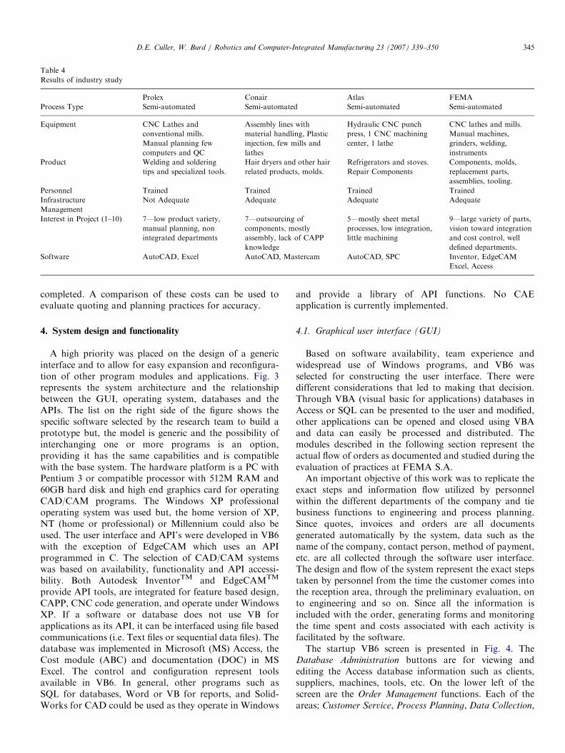
The ITCR encourages academic researchers to defineprojects that directly benefit local industry and that anytechnology or software applications can be implemented.For this project, the team performed a study related toautomation being used in a variety of different manufac-turing companies. Based on the results of the evaluation,the academic team selected the company to be used as amodel for subsequent system development. Questionnaires,interviews and plant visits were used for the final analysisand selection.
3.1. Industry study details
The following items were used as a guideline whenevaluating each company: Type of industry, Productfamilies, Production type, Design, Engineering, Qualitycontrol, Software, Cost control and Equipment. The teampaid close attention to how interested management was insupporting project objectives since they would have to beopen to sharing many private details related to businesspractices. The discrete part manufacturing sector, whereCAPP and CNC machining is most prevalent, wasidentified as the most appropriate for proposed researchdue to the computerized nature of these tasks and theability to closely monitor orders. The results of theevaluation are summarized in Table 4.
3.2. Company selection
FEMA Industrial S.A., (column 4 in the table above)was selected because of the variety of products manufac-tured, existing computer resources available and theenthusiasm demonstrated by management to collaboratewith the academic team. FEMA employs sixty five peoplein six departments and uses both conventional and CNCmachines. In addition to machining processes, secondaryoperations such as heat treatments, finishes, welding andinspection make FEMA one of the top five shops in thecountry. An in-house material supply store and separatequality control and engineering departments, made theenvironment a good match for research objectives.Improvements in design and process planning softwarealso qualified FEMA as the best candidate for computer-ized information management. FEMA management wasopen and enthusiastic about working with the university, akey for success in collaborative projects.The business cycle at FEMA is divided into six
departments; Administration, Customer Service, Design,Engineering, Production and Quality Control. The teamclosely monitored document flow and interviewed keypersonnel to identify how orders are processed and costsaccumulated. The team identified three critical points whenthe overall cost of a product can be evaluated: (1) the pricequoted to the customer, (2) after design and processplanning are completed and (3) when the product is
ARTICLE IN PRESS
Table 4
Results of industry study
Prolex Conair Atlas FEMA
Process Type Semi-automated Semi-automated Semi-automated Semi-automated
Equipment CNC Lathes and
conventional mills.
Manual planning few
computers and QC
Assembly lines with
material handling, Plastic
injection, few mills and
lathes
Hydraulic CNC punch
press, 1 CNC machining
center, 1 lathe
CNC lathes and mills.
Manual machines,
grinders, welding,
instruments
Product Welding and soldering
tips and specialized tools.
Hair dryers and other hair
related products, molds.
Refrigerators and stoves.
Repair Components
Components, molds,
replacement parts,
assemblies, tooling.
Personnel Trained Trained Trained Trained
Infrastructure Not Adequate Adequate Adequate Adequate
Management
Interest in Project (1–10) 7—low product variety,
manual planning, non
integrated departments
7—outsourcing of
components, mostly
assembly, lack of CAPP
knowledge
5—mostly sheet metal
processes, low integration,
little machining
9—large variety of parts,
vision toward integration
and cost control, well
defined departments.
Software AutoCAD, Excel AutoCAD, Mastercam AutoCAD, SPC Inventor, EdgeCAM
Excel, Access
D.E. Culler, W. Burd / Robotics and Computer-Integrated Manufacturing 23 (2007) 339–350 345
completed. A comparison of these costs can be used toevaluate quoting and planning practices for accuracy.
4. System design and functionality
A high priority was placed on the design of a genericinterface and to allow for easy expansion and reconfigura-tion of other program modules and applications. Fig. 3represents the system architecture and the relationshipbetween the GUI, operating system, databases and theAPIs. The list on the right side of the figure shows thespecific software selected by the research team to build aprototype but, the model is generic and the possibility ofinterchanging one or more programs is an option,providing it has the same capabilities and is compatiblewith the base system. The hardware platform is a PC withPentium 3 or compatible processor with 512M RAM and60GB hard disk and high end graphics card for operatingCAD/CAM programs. The Windows XP professionaloperating system was used but, the home version of XP,NT (home or professional) or Millennium could also beused. The user interface and API’s were developed in VB6with the exception of EdgeCAM which uses an APIprogrammed in C. The selection of CAD/CAM systemswas based on availability, functionality and API accessi-bility. Both Autodesk InventorTM and EdgeCAMTM
provide API tools, are integrated for feature based design,CAPP, CNC code generation, and operate under WindowsXP. If a software or database does not use VB forapplications as its API, it can be interfaced using file basedcommunications (i.e. Text files or sequential data files). Thedatabase was implemented in Microsoft (MS) Access, theCost module (ABC) and documentation (DOC) in MSExcel. The control and configuration represent toolsavailable in VB6. In general, other programs such asSQL for databases, Word or VB for reports, and Solid-Works for CAD could be used as they operate in Windows
and provide a library of API functions. No CAEapplication is currently implemented.
4.1. Graphical user interface (GUI)
Based on software availability, team experience andwidespread use of Windows programs, and VB6 wasselected for constructing the user interface. There weredifferent considerations that led to making that decision.Through VBA (visual basic for applications) databases inAccess or SQL can be presented to the user and modified,other applications can be opened and closed using VBAand data can easily be processed and distributed. Themodules described in the following section represent theactual flow of orders as documented and studied during theevaluation of practices at FEMA S.A.An important objective of this work was to replicate the
exact steps and information flow utilized by personnelwithin the different departments of the company and tiebusiness functions to engineering and process planning.Since quotes, invoices and orders are all documentsgenerated automatically by the system, data such as thename of the company, contact person, method of payment,etc. are all collected through the software user interface.The design and flow of the system represent the exact stepstaken by personnel from the time the customer comes intothe reception area, through the preliminary evaluation, onto engineering and so on. Since all the information isincluded with the order, generating forms and monitoringthe time spent and costs associated with each activity isfacilitated by the software.The startup VB6 screen is presented in Fig. 4. The
Database Administration buttons are for viewing andediting the Access database information such as clients,suppliers, machines, tools, etc. On the lower left of thescreen are the Order Management functions. Each of theareas; Customer Service, Process Planning, Data Collection,

ARTICLE IN PRESS
Fig. 3. Model for the development of computer aided process planning system.
Fig. 4. Main operating screen of CAPP system.
D.E. Culler, W. Burd / Robotics and Computer-Integrated Manufacturing 23 (2007) 339–350346
Cost Analysis and Documentation are described in thefollowing sections. The interface was created with easy tochange logos and editable data for quick reconfigurationand adaptability. Currently these changes cannot be madeat runtime and require the services of an experienced VBprogrammer.
4.2. Description of modules
Customer service: The first step in processing an orderrelates to gathering customer information such as the nameof the company, contact person, date, general descriptionof product, etc. Next, a planner must study the product forthe purpose of creating a quote. The material, specifica-tions, processes, inspection methods, time estimates andthe number of parts needed are necessary components ofthe initial evaluation. The final step of this phase is thegeneration of the quote.
Computer aided process planning: Once the quote hasbeen approved by the customer, design and processplanning activities can be performed using CAD/CAM.
Decisions made here have critical consequences on the finalcost of the component or assembly. The results of thisphase include the design specifications, a complete processplan, NC programs and information related to machiningtimes, material, tooling, etc. The CAD phase of CAPP iscompleted with Inventor and includes the 3D solid modeldesign of the part, feature definitions, tolerance and finishspecifications and final drawings. Because of the compat-ibility between Inventor and EdgeCAM, the solid model isimported without creating a file in a neutral format (i.e.IGES, STEP, DXF) and features are automaticallyrecognized using EdgeCAM’s feature finder. This integra-tion is made more powerful in that if the design is changedat some point in Inventor, EdgeCAM notifies the user andtool paths and machining conditions can be updated toreflect those changes. The EdgeCAM strategy manageroffers solutions to a problem experienced by many CAMprogrammers—how to capture information about amachining job and apply some or all of it to subsequentjobs. Strategy Manager includes an interactive, graphicalmethod to define and capture the way in which parts are tobe cut. The strategies created can then be re-applied toother EdgeCAM parts to automate the programmingprocess. EdgeCAM Strategy Manager combines logic andflow chart methodology to capture working practices anddefine strategies. Once planning is completed, informationthat can be retrieved through the CAD API includes a billof materials and mass properties while machining statisticsand tooling data comes from the CAM API. As mentionedearlier, only examples of API programs were constructedfor this project, the rest of the data was collected from theuser and processed in cost calculations and documentcreation. A key part of extending CAPP to include businessfunctions is the use of API’s to retrieve data related todesign and manufacturing in real time. There are manylimitations with API programming languages becausecommercial CAD/CAM systems vary considerably withrespect to database structures and user interaction.Descriptions of Inventor and EdgeCAM functionalitywhich directly relate to this project are shown below andthe process planning screen from the VB6 interface isdisplayed in Fig. 5.

ARTICLE IN PRESS
Fig. 5. Process planning screen of system.
D.E. Culler, W. Burd / Robotics and Computer-Integrated Manufacturing 23 (2007) 339–350 347
Autodesk Inventor 6TM: 3D Parametric Solid
Modeling and Visual Basic Programming InterfaceInventor is a fully functional 3D solid modeling. Thesoftware simplifies the transition from 2D to 3D,provides tools for managing large projects andfacilitates the output of detailed mechanical drawingsand documentation. Inventor produces files that can beimported directly into many commercial CAM andCAE systems. The Autodesk Inventor API enablesusers and 3rd party developers to extend and customizeInventor. Microsoft Visual Basic for Applications(VBA) provides a programming environment withinInventor. For example, you can write a program thatinterfaces with your company’s database to obtain thecurrent price for components. You can also write aprogram that extracts data from assemblies to provideMRP systems with their information [19].
PathTrace EdgeCAM 8.75TM: Solid Machinist and
Programming Interface‘‘EdgeCAM Solid Machinist provides the ability todirectly load and machine solid files without the needfor translation. The Feature Finder command willautomatically find prismatic features on the solidmodel. Identification tools allow you to manuallyidentify machinable features. Associativity with thedesign model is retained. Strategies provide a means ofautomatically generating the optimum set of machininginstructions. By building conditions into yourstrategies you can make them adapt; for example tofeature attributes and materials. EdgeCAM offersvarious programming tools to automate and customizesystem operation. PCI is a parametric macro language.PDI is the C language API for EdgeCAM that can beused to access internal databases and export/importdata [20].
Data collection: Once the process plan is complete and
sent to the shop floor, knowing where the order is wouldallow for a more accurate estimate of time to completionand supply valuable information for customers andplanners. The data collection module currently collectsfeedback from operators related to final processing timesand changes made to process plans. This tool is useful forimproving estimating and planning procedures. The screencontains a layout of the shop floor with VB interactiontextboxes that prompt the user to type in informationrelated to processes being carried out at each station.Cost analysis: This module is a cost calculator that sumsthe costs of all the individual activities utilizing the ABCmethodology described earlier. When the user selects aspecific order number, all the activities that contributed todesigning, manufacturing and inspecting the product arelisted on the screen for review and analysis. At this pointthere is a comparison made between the quoted cost, thecost after process planning and the real cost once real datahas been collected.
Documentation and job history: The final module of thesystem is used to create the documents with the informa-tion related to each order. By storing the data input in theprevious steps, a complete job history is available in digitalformat. The data is output to standardized forms which arevery easy to personalize for different companies. Oneobvious advantage to having this job history is the abilityto retrieve existing plans when similar orders are processedin the future. The types of documents available include thequote, part drawing, work order, material, order, processplan, and CNC program among others. The templatesrepresenting all the documents mentioned above have beencompleted and the automatic data insertion using VB hasbeen done for the quote, work order and materialrequirements.
5. Case study
A final evaluation of the system was performed usingvarious test parts so that real data could be studied andpresented. A standard spacer for a pipe flange connectionwas selected because of the combination of turning andmilling required and the simplicity and size of the partdesign (see Fig. 6).A meeting with FEMA engineers allowed the team to
follow the same steps as any other customer approachingthe shop with a job, completing both an evaluation of theprocesses and material required as well as the preparationof an official quote. A 3D model and drawings were createdwith Inventor and used as input to the CAPP system wherefeatures were automatically identified and programmedusing the EdgeCAM Solid Machinist application. Thedecisions made by the CAPP system included the tooling tobe used for rough and finish cuts, the number of cuts to bemade, how much material to leave for finish passes and thecutting conditions based on the material that was selected(i.e. speeds and federates). The results from this phase were

ARTICLE IN PRESS
Fig. 6. Drawing and 3D model of sample part.
Fig. 7. Activity based costing breakdown for sample part.
Fig. 8. Set-up sheet for sample part.
D.E. Culler, W. Burd / Robotics and Computer-Integrated Manufacturing 23 (2007) 339–350348
the NC programs for cutting each feature of the part on theselected machine tool, NC verification images, tooling dataand cutting statistics such as the time for the operations,volume of material removed and tool changes made basedon the sequence of operations selected by the user. Theinformation was placed on a report generated by Edge-CAM in web page format (html) and the variables used bythe EdgeCAM API were identified for subsequent proces-sing. The results of the CAPP and CAM phases of theprocess were similar to the strategies selected manually byexperienced machinists and were not optimized based ontime or cost criteria, the strategies stored in the EdgeCAMgraphical flowchart format were used to create the partprograms.
Next, the ABC application was tested using the formulasand methods presented in Section 2.2. An order of 50 parts(Fig. 6) made out of stainless steel. Fig. 7 shows thebreakdown of costs in the following order: customerservice, design, planning, engineering, manufacturing,quality control, setup, material handling, shipping, market-ing and sales and administration. The three columnsrepresent the estimated cost used for the quote, the actualcost based on ABC and the difference. This comparison
could be a valuable tool for engineers responsible for quotepreparation and job estimates because the actual differ-ences can be traced directly to the activity responsible forthe variation.

ARTICLE IN PRESS
Table 5
Results and benefits of system implementation
Item Before changes After changes
Customer service Customers were directly routed through engineers
and job evaluators without screening and
introduction into the order chain. Critical personnel
were used for screening and basic customer data and
needs were not collected.
A reception desk was created to collect basic order
information and engineers were trained to evaluate
incoming jobs and produce quotes. Efficiency in job
entry and quoting increased up to 15% over the first
3 months.
Engineering evaluation A very informal interview was conducted to gather
job information, including part and material
specifications, quantities, tolerances and finishes.
Formal job evaluations drastically improved the
transition from design to manufacturing and
eliminated the duplication of planning decisions once
job quote has been approved.
3D CAD drawings 2D models and drawing layouts were produced using
AutoCAD and Mechanical Desktop. Other parts
were produced directly from the sketches and
informal paperwork often turned in by customers.
All parts are produced in Inventor 3D solid modeling
and drawings created from 3D model. Time savings
are estimated at 20% once personnel are completely
trained. The volume of work and the increased
complexity of designs have created new
opportunities.
Paper based communications All communication between departments was done
using a series of 12 different forms that were filled
out and distributed by hand, often by critical
personnel. The lost forms and misinterpretations
regularly caused delays.
Quotes, invoices, drawings and supply orders were
computerized, eliminating expenses including paper,
time, errors and saving job histories.
Activity based costing methods An incomplete understanding of costs incurred
during order processing caused overcharging and
undercharging of customers. Forecasting and
analysis of data was very difficult due to the
incompleteness of job histories and actual costs
incurred during engineering and manufacturing.
Forecasting and monthly/yearly evaluations became
common practice and company losses have led to a
more thorough understanding of how costs are
managed and jobs processed. Although difficult to
completely quantify, it is estimated that up to 15%
savings have been attributed to changes from ABC.
D.E. Culler, W. Burd / Robotics and Computer-Integrated Manufacturing 23 (2007) 339–350 349
The above mentioned categories are all related toindirect costs which is the basis for ABC as explained inSection 2.2. In the top section of Fig. 7 are the direct costsof raw materials and components (i.e. Gaskets, bolts andnuts). A set of documents was completed using the datacollected during the trial run. An example of the processsetup sheet is shown in Fig. 8. The information includes thelist of operations, tooling requirements, fixture orientationsand images of setups.
The values obtained were very comparable to thecorresponding information produced from manually pro-cessing the order but, due to the limitations of thecompanies’ CAD/CAM capabilities and the estimation ofcosts not available during the trial, exact comparisons anda more detailed evaluation of the system were not possible.
6. Results of implementation phase
Once work was completed, the customer service and thepreliminary process planning modules were implemented atFEMA Industrial S.A. This included the databases in MSAccess, VB graphical user interface and programs forgenerating the quote and work order. Installing thecomplete system was not possible because CAD andCAM integration were in their early stages and computingresources were not available in every department tofacilitate digital data distribution. The customer serviceand quote generation portions of the program were
installed and utilized by the company for evaluating newjobs and documenting the processes and correspondingtimes which were estimated for the quote. One of thebiggest benefits of the project to the company was themotivation to migrate to a 3D solid modeling environmentand purchase EdgeCAM to take advantage of an expand-ing mold and die market in the country. The mostimportant results and benefits are summarized in Table 5.
7. Conclusions
Continued advances in CAPP and CAD/CAM technol-ogy are constantly creating opportunities to reach moreadvanced levels of integration between administration,engineering and shop floor production. This paper lays thefoundation for further work in API programming toretrieve data critical for accurate handling of customerorders and more efficient distribution of informationbetween departments. The important contributions of thisresearch on are: (1) it presents an architecture for a CAPPsystem with an integrated costing tool for evaluatingcompany performance and providing valuable feedback toplanners and management personnel, (2) it combinesdeveloped and commercial software, including independentCAD and CAM systems, in an framework that can beexpanded and modified to meet company requirements and(3) it utilizes a single user interface to combine bothadministrative and engineering tasks.

ARTICLE IN PRESSD.E. Culler, W. Burd / Robotics and Computer-Integrated Manufacturing 23 (2007) 339–350350
The results from this project received praise from localmanufacturers and were published in both university andlocal newspapers [21]. Other companies that viewed thesoftware also expressed the need that exists for softautomation tools that bring administration and engineer-ing together. An important key to the success of thisproject, aside from the team effort and the motivationexhibited by the students, was the pre-existing relationshipwhich existed between the author and the owners of themachine shop. Other projects to implement CNC andresolve machine code format and communications pro-blems had already been completed. This resulted in aconfidence to share real information and openness betweenthe university participants and the shop management,allowing the system to reflect day to day operations.
Acknowledgements
Fellow professors (ITCR Professors: Carmen ElenaMadriz, M.S., Ivannia Hasbum, M.S.), students (Studentsin Industrial Engineering: Hernan Guerra, Luis CarlosRivas, Hellen Machado, Melania Abarca, Ileana Vargasand Esteban Solis) and representatives (Owners of FEMAIndustrial S.A.: Luis Fernando Masıs P., Marvin A. MasısP.) of FEMA Industrial deserve much of the credit for thesuccess of this project. The team effort and dedicationallowed us to reach our goals.
References
[1] Khoshnevis B, Park JY, Sormaz DN. A cost based system for
concurrent part and process design. The Engineering Economist
1994;40(1):101–24.
[2] Ahmad, Nafis, Anwarul Haque AFM, Hasin AA. Current trends in
computer aided process planning. Proceedings of the seventh annual
paper meet and 2nd international conference, The Institution of
Engineers, Bangladesh, Mechanical Engineering Division 25–27.
Paper No. 10; 2001. p. 81–92.
[3] Groover, Michael. Fundamentals of modern manufacturing. Engle-
wood Cliffs, NJ: Prentice-Hall; 1997.
[4] Chang TC, Wysk RA. An introduction to automated process
planning systems. Englewood Cliffs, NJ: Prentice-Hall; 1995.
[5] McMahon, Chris, Browne, Jimmie. CAD/CAM: principles, practice
and manufacturing management. Reading, MA: Addison-Wesley;
1998. p. 314–5.
[6] DRM Associates. CAPP, [Online] 2003 [cited 2004, Dec.10]; accessed
on: URL: /http://www.npd-solutions.com/index.htmlS.
[7] Usher JM, Fernandes KJ. A two phased approach to dynamic
process planning: 19th international conference on computers and
industrial engineering, vol. 31(1,2); 1996. p. 173–6.
[8] Dargie P, Parmeshwar K. A computer aided design system for
preliminary material and manufacturing process selection. Trans
ASME J Mech Design 1982;104:126–35.
[9] Chan K, Wright P. COMPASS: Computer oriented materials,
processes, and apparatus selection system. J Manufacturing Systems
1998;17(4):275–86.
[10] Shen W, Nore D. Multi-agent systems for concurrent design and
manufacturing. London: Taylor and Francis Publishing Co.; 2001.
[11] Cecil J, Rodriquez C. An internet based approach to support
distributed product development. Proceedings of the annual IIE
research conference, Portland, Oregon, 2003 May 17–21.
[12] MetCAPPs—Computer Aided Process Planning [Online] 1999 [cited
2004, Dec.10]; accessed on: URL: /http://www.cimplex.com/met-
capp.htmS.
[13] Shaw C, Feng. Preliminary design and manufacturing planning
integration using web-based intelligent agents. J Intelligent Manuf
2005;16:423–37.
[14] Cooper R. The rise of activity-based costing- part one: what is an
activity-based cost system? J Cost Manage 1988;2(2):45–54.
[15] Cooper R, Kaplan RS. Measure cost right: make the right decisions.
Harvard Business Rev 1988; September–October: 96–102.
[16] Johnson HT. Activity management: reviewing the past and future of
cost management. J Cost Manage 1990; Winter: 3(4): 4–7.
[17] Roztocki, Narcyz. Introduction to activity based costing [Online]
2001 [cited 2004, Oct.10]; accessed on: URL: /http://www.pitt.e-
du.AFShome/r/o/roztocki/public/html/abc/abctutor/index.htmS.
[18] Roztocki, Narcyz. Valenzuela Jorge F. A procedure for smooth
implementation of activity based costing in small companies [Online]
2001 [cited 2004, Nov. 10]; accessed on: URL: /http://www.pitt.edu/
�roztocki/abc/abc.htmS.
[19] Autodesk Inventor 6TM. Software help files, Design Techniques,
2004.
[20] PathTrace EdgeCAM 8.75TM. Software help files, Solid Machinist,
2004.
[21] Nunez, Maria Jose. Software renueva industria metalmecanica,
Periodico La Republica, 2002, June 21. p. 11.