a fully autonomous indoor quadrotorjmconrad/ecgr6185-2013-01/... · the quadrotor is given a goal...
TRANSCRIPT

A Fully Autonomous Indoor QuadrotorSlawomir Grzonka, Giorgio Grisetti, and Wolfram Burgard
Presented by: Bhanuprasad PatibandlaECGR 6185 Adv. Embedded Systems
February 20th 2013
1/16
Laboratory for Autonomous Intelligent Systems, University of Freiburg, Germany.
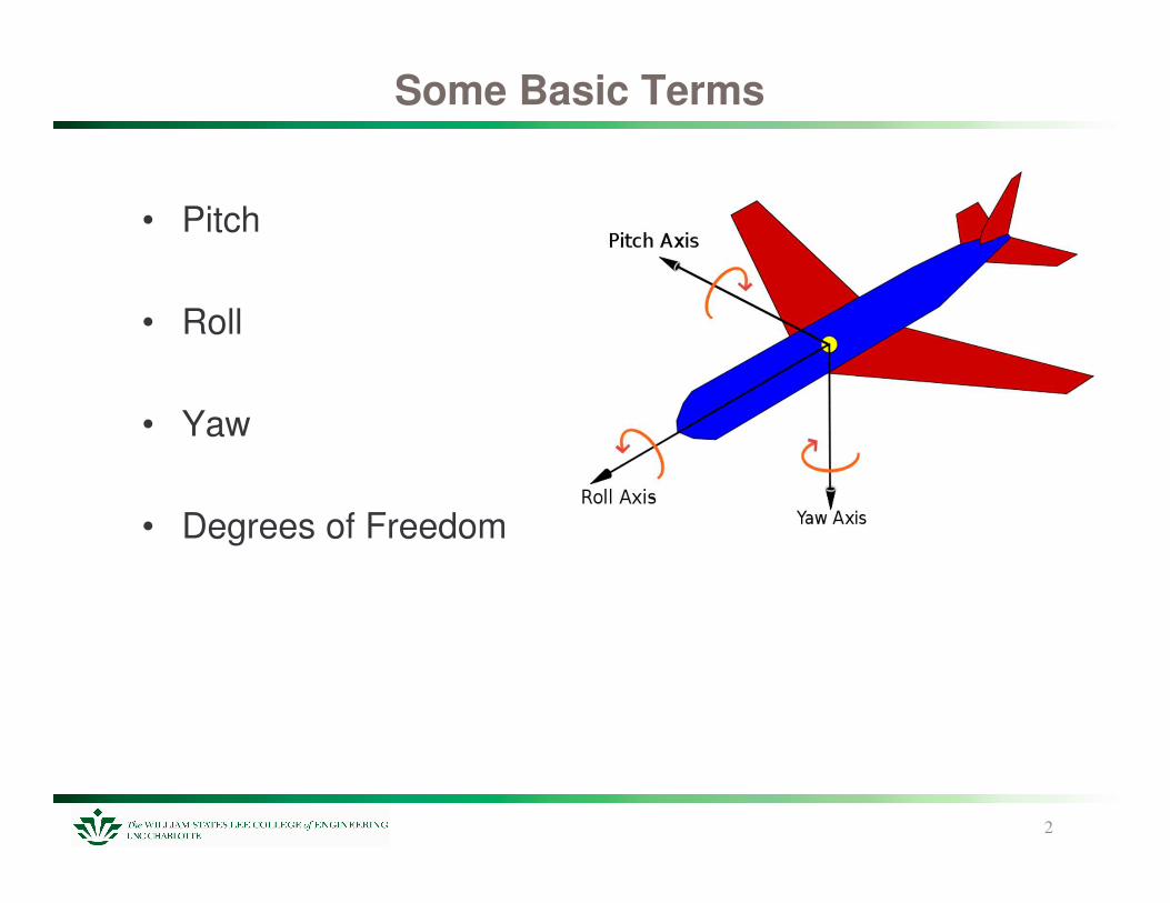
Some Basic Terms
• Pitch
• Roll
• Yaw
• Degrees of Freedom
2
Hardware Architecture
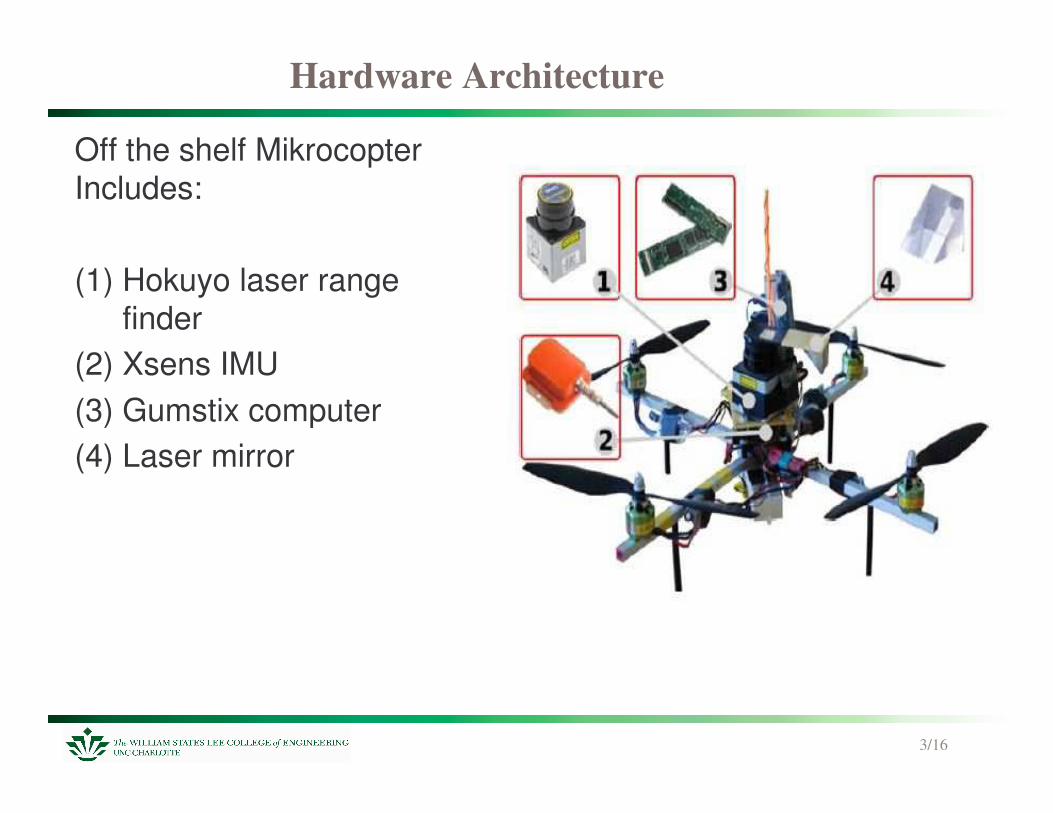
Off the shelf MikrocopterIncludes:
(1) Hokuyo laser range finder
(2) Xsens IMU(3) Gumstix computer(4) Laser mirror
3/16
4/16
• Based on a modular architecture - modules communicate via the network by using a publish–subscribe mechanism.
• Device Drivers on-board. Computational Algorithms on a remote PC communicating over wireless with the platform.
• 4 Degrees Of Freedom consisting of the 3-D position (x, y, z) and the yaw angle �.
• The only sensor that is used to estimate these 4DOF and detecting obstacles is the laser range scanner.
• No odometry measurements. Incremental movements in (x,y,�) are estimated by 2-D laser scan matching.
Navigation System

The SLAM Algorithm-1
5/16
.
The SLAM Algorithm-2
6/16
How it works
7/16
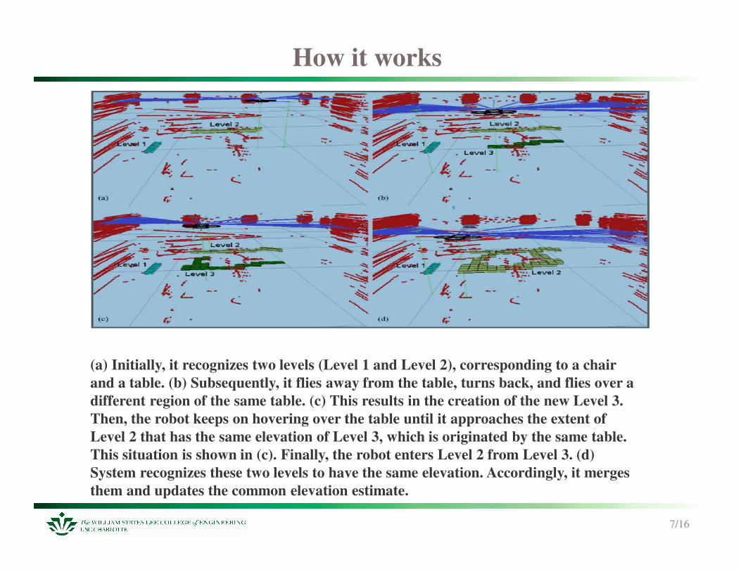
(a) Initially, it recognizes two levels (Level 1 and Level 2), corresponding to a chair and a table. (b) Subsequently, it flies away from the table, turns back, and flies over a different region of the same table. (c) This results in the creation of the new Level 3. Then, the robot keeps on hovering over the table until it approaches the extent of Level 2 that has the same elevation of Level 3, which is originated by the same table. This situation is shown in (c). Finally, the robot enters Level 2 from Level 3. (d) System recognizes these two levels to have the same elevation. Accordingly, it merges them and updates the common elevation estimate.
High-Level Control for Pose and Altitude
8/16
• The pitch and the roll are controlled by two independentPIDs that are fed with the x and the y coordinates ofthe robot pose.u� = Kp (x − x�) + Ki ex + Kd vx
• The yaw is controlled by the following controller:u� = Kp (� − ��)
• The altitude is controlled by a PID controller that utilizes thecurrent height estimate z, the velocity vz , and the current batteryvoltage Ut , respectively.uz = C(Ut) + Kp (z − z�) + Ki ez + Kd vz
Path Planning and Obstacle Avoidance
9/16
• Path planning module is based on D-Lite algorithm which can reuse previous solutions to correct an invalid path and is done in two steps.
• A path in the x-y-z plane is computed but only action in x-y plane are considered. The known elevation of the surface below is used to determine a possible change in altitude the robot would have to take when moving to a nearby cell.
• Once this trajectory is calculated with D Lite its is augmented with the � component.

• Experimental Results
10
11/16
SLAM
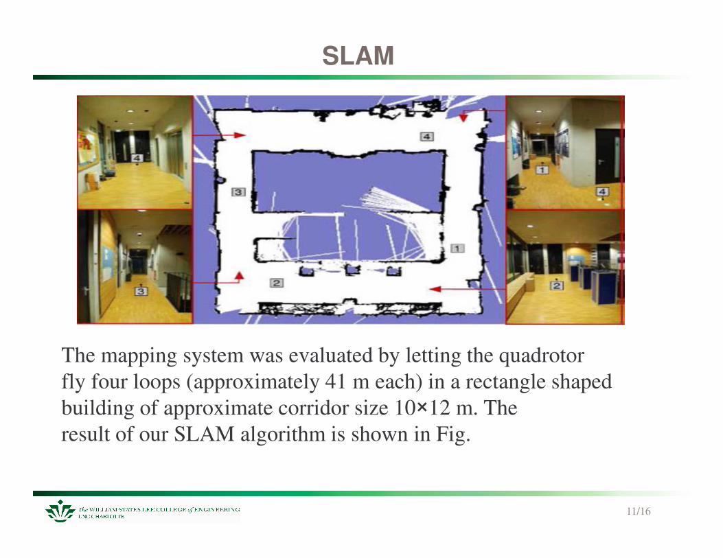
The mapping system was evaluated by letting the quadrotorfly four loops (approximately 41 m each) in a rectangle shapedbuilding of approximate corridor size 10�12 m. Theresult of our SLAM algorithm is shown in Fig.
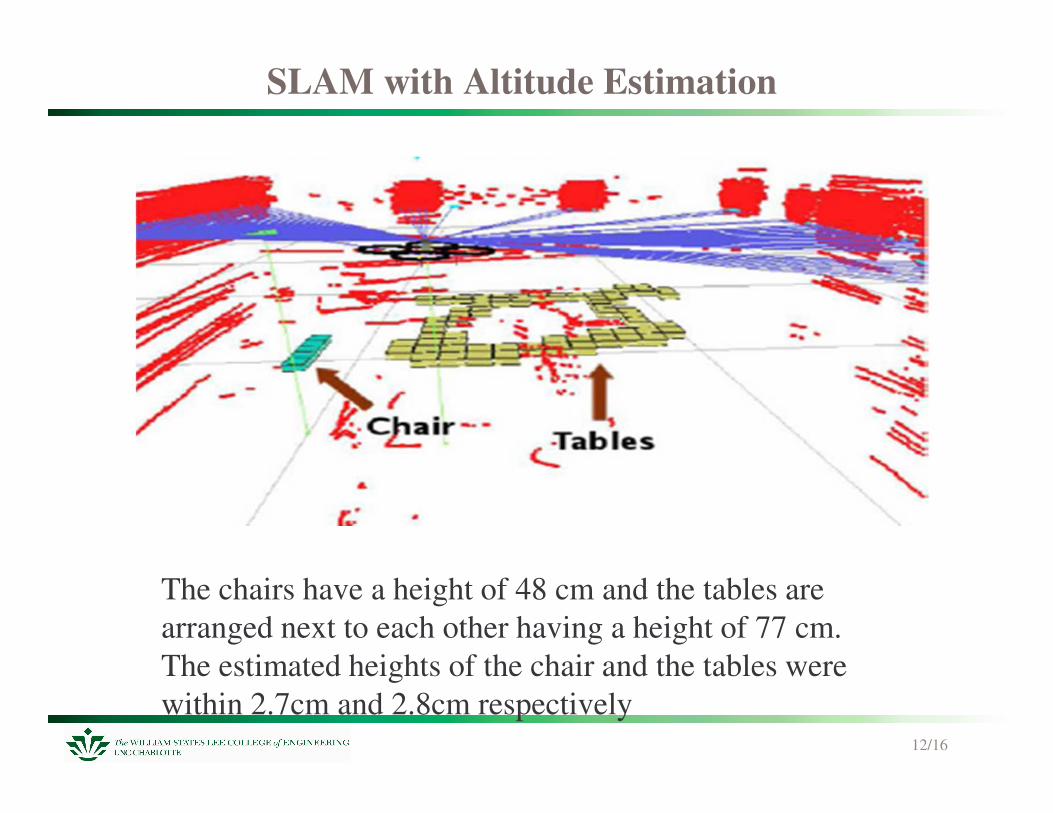
SLAM with Altitude Estimation
12/16
The chairs have a height of 48 cm and the tables arearranged next to each other having a height of 77 cm.The estimated heights of the chair and the tables were within 2.7cm and 2.8cm respectively

Path planning and Dynamic Obstacle Avoidance
13/16
The quadrotor is given a goal point 5 m in front of it. • The planned path is shown in
the left image. • A person enters the corridor
(shaded area) and blocks the robot’s path, which results in an invalid plan. The quadrotor therefore hovers around the last valid way point (second image).
• In the third image, the person moved back, leaving the quadrotor enough space for a de-tour.

Pose Control
14/16
• During the yaw stabilization experiment, the quadrotor was required to rotate to 0�, while the user manually turned the robot once in a while to a random orientation.
• Within the pose stability experiment, the quadrotor was set to hover at (0, 0) but was manually moved backwards once in a while and required to fly autonomously back to the initial pose.

Conclusion
15/16
• A complete navigation solution that approaches differentaspects of localization, mapping, path-planning, heightestimation, and control has been achieved.
• Since the system does not rely on characteristics of the flying platform like the dynamics model, it can be easily adapted to different flying vehicles.
• The whole system can run on-board with a more advanced processor like Intel Atom processors.
• Future plans include integrating a time of flight camera into the system.
References
[1] Aircraft Principal Axes [Web Photo] http://en.wikipedia.org/wiki/Aircraft_principal_axes
[2] Slawomir Grzonka, Giorgio Grisetti, and Wolfram Burgard, “A Fully Autonomous Indoor Quadrotor” in IEEE Transactions on robotics, vol. 28, No. 1, February 2012
16/16