a generic framework for context-aware routing and its ... · a generic framework for context-aware...
TRANSCRIPT

A Generic Framework for Context-Aware Routing and its Imple-
mentation in Wireless Sensor Networks
Bernd-Ludwig Wenning, Andreas Timm-Giel, Carmelita Görg
Communication Networks, University of Bremen, Germany
Abstract
As networks become more dynamic, the awareness of the network members’ current context is of growing im-
portance. This can be said especially for communication networks, but also for other types of networks, e.g. lo-
gistic networks. Context-aware routing takes this context information into account when selecting routes in such
networks. This paper introduces a novel generic framework for context-aware routing, including the message
flow as well as the route decision method. The framework is not limited to a single application domain, but it is a
generalized approach that can be adapted and specialized for various application domains. As an example, a
wireless sensor network scenario is presented where this routing framework is applied.
1 Introduction
Routing in dynamically changing networks needs to
react to the dynamics to achieve efficient and reliable
network usage. All sources of dynamics in these net-
works can be considered as context for the route se-
lection. Therefore, a routing that considers the dynam-
ics for the route selection can be named context-aware
routing.
Context-aware routing generally implies that there are
multiple context criteria which influence the route de-
cision process. Some context-aware routing ap-
proaches for communication networks are known
from current literature, but they are usually tailored to
a specific use case. The most general formulations are
described in [1] and [3]. Both of them are using addi-
tive utility functions to combine the multiple criteria
into one decision metric.
CAR (Context-Aware Routing, [1]) is a routing proto-
col designed for ad hoc networks. It uses context in-
formation such as a node’s connectivity and battery
status to determine a delivery probability that denotes
whether the node is a reliable next hop towards the
destination. For wireless sensor networks, SCAR
(Sensor Context-Aware Routing, [2]) has been derived
from CAR as an adaptation. Both CAR and SCAR are
proactive routing methods where each node evaluates
its own delivery probability and periodically sends the
result to its neighbors.
In [3], a Normalized Weighted Additive Utility Func-
tion (NWAUF) is defined for multi-criteria routing in
wireless ad hoc networks. In the provided example,
energy, latency and bit error rate are used as criteria.
The NWAUF is evaluated by each node in the net-
work and may be used either with global or with local
network status knowledge.
Both the NWAUF and the decision utility in CAR are
very similar. They utilize an additive utility for local
decisions at the individual nodes. All nodes proac-
tively maintain routing tables.
The goal of the work presented here is to create a ge-
neric framework for context-aware routing that pro-
vides more flexibility than the aforementioned ap-
proaches.
The paper is organized as follows: Section 2 intro-
duces the messages that are defined for this frame-
work, as well as the flow of these messages. The deci-
sion system that is used in the framework is described
in section 3. After this generic framework description,
Reactive Environmental Monitoring Aware routing
(Reactive EMA) is described as an implementation
for Wireless Sensor Networks in section 4. A simula-
tion scenario and simulation results are shown and
discussed in section 5. The paper concludes with a
summary and outlook in section 6.
2 Generic context-aware rout-ing framework
The context information that is present in a network is
usually distributed among the network nodes. To util-
ize this context information for route decisions, either
the decisions have to be done distributed among the
participating nodes, or the relevant context informa-
tion has to be collected at the node that decides.
Routing protocols for mobile ad-hoc networks
(MANETs) already have methods of collecting or ex-
changing information that is relevant for routing, ei-
ther proactive, e.g. OLSR (Optimized Link State
Routing, [4]) or reactive, e.g. DSR (Dynamic Source
Routing, [5]), AODV(Ad Hoc On-Demand Distance
Vector, [6]). These methods can be borrowed and ex-
tended for context-aware routing.
The context-aware routing method introduced in this
work is supposed to provide high flexibility. A send-
ing node should be able to individually decide which
context information to consider and how to prioritize
among the context criteria. This flexibility means that
for each route decision, the decision function may
Wenning, B.-L.; Timm-Giel, A.; Görg, C.: A generic framework for context-aware routing and its implementation in wireless sensor networks.In: Mobilkommunikation - Technologien und Anwendungen, Vorträge der 14. ITG-Fachtagung, Osnabrück 2009, pp. 53-58.
contain an individual set of context criteria. Achieving
this through a proactive routing approach would re-
quire that the values of all known context criteria
would have to be disseminated in the network peri-
odically, so that each node can always decide which
of those criteria to use and how to combine them.
In a reactive approach, the sending node has to spec-
ify during a route discovery phase which context in-
formation is currently of interest. This means that not
all of the context criteria have to be kept up to date in
the entire network all the time, but they can be col-
lected on demand.
For the routing framework presented in this paper, a
reactive source routing approach is chosen to gather
the context information from the network. This con-
text information has to include:
• Specification which context criteria are used
• Parameterized rules to combine the context
criteria values
• The criteria values themselves.
The nodes in the network need to know how to inter-
pret the context information, i.e. when they get a set
of parameters for combining the criteria values, they
need to have knowledge about what these parameters
mean. Also, they have to be able to interpret the in-
formation about which criteria are used. Therefore,
each node must have a local knowledge base for this,
and that knowledge base must be the same for all
nodes. If this is fulfilled, numeric identifiers can be
used for the selected criteria and for the combination
rules.
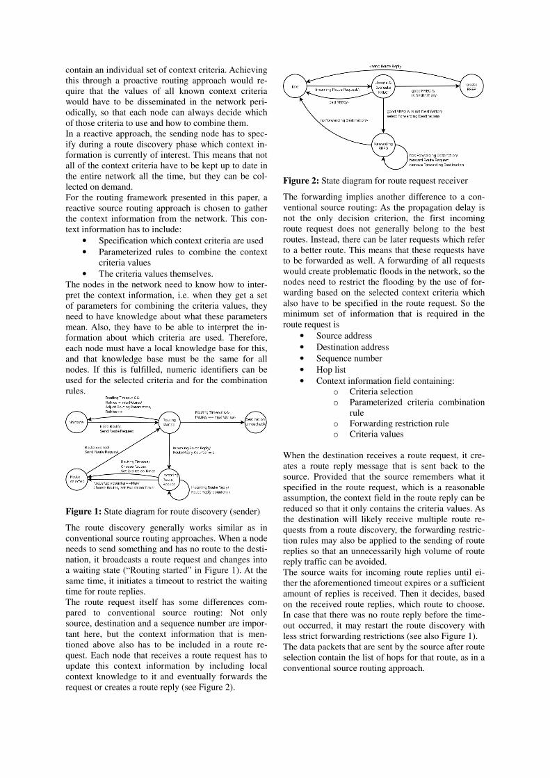
Figure 1: State diagram for route discovery (sender)
The route discovery generally works similar as in
conventional source routing approaches. When a node
needs to send something and has no route to the desti-
nation, it broadcasts a route request and changes into
a waiting state (“Routing started” in Figure 1). At the
same time, it initiates a timeout to restrict the waiting
time for route replies.
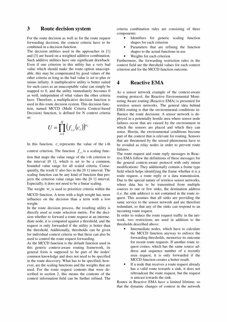
The route request itself has some differences com-
pared to conventional source routing: Not only
source, destination and a sequence number are impor-
tant here, but the context information that is men-
tioned above also has to be included in a route re-
quest. Each node that receives a route request has to
update this context information by including local
context knowledge to it and eventually forwards the
request or creates a route reply (see Figure 2).
Figure 2: State diagram for route request receiver
The forwarding implies another difference to a con-
ventional source routing: As the propagation delay is
not the only decision criterion, the first incoming
route request does not generally belong to the best
routes. Instead, there can be later requests which refer
to a better route. This means that these requests have
to be forwarded as well. A forwarding of all requests
would create problematic floods in the network, so the
nodes need to restrict the flooding by the use of for-
warding based on the selected context criteria which
also have to be specified in the route request. So the
minimum set of information that is required in the
route request is
• Source address
• Destination address
• Sequence number
• Hop list
• Context information field containing:
o Criteria selection
o Parameterized criteria combination
rule
o Forwarding restriction rule
o Criteria values
When the destination receives a route request, it cre-
ates a route reply message that is sent back to the
source. Provided that the source remembers what it
specified in the route request, which is a reasonable
assumption, the context field in the route reply can be
reduced so that it only contains the criteria values. As
the destination will likely receive multiple route re-
quests from a route discovery, the forwarding restric-
tion rules may also be applied to the sending of route
replies so that an unnecessarily high volume of route
reply traffic can be avoided.
The source waits for incoming route replies until ei-
ther the aforementioned timeout expires or a sufficient
amount of replies is received. Then it decides, based
on the received route replies, which route to choose.
In case that there was no route reply before the time-
out occurred, it may restart the route discovery with
less strict forwarding restrictions (see also Figure 1).
The data packets that are sent by the source after route
selection contain the list of hops for that route, as in a
conventional source routing approach.
3 Route decision system
For the route decision as well as for the route request
forwarding decision, the context criteria have to be
combined in a decision function.
The decision utilities used in the approaches in [1]
and [3] are based on a weighted additive combination.
Such additive utilities have one significant drawback:
Even if one criterion in this utility has a very bad
value which should make the route option unaccept-
able, this may be compensated by good values of the
other criteria as long as the bad value is set to plus or
minus infinity. A multiplicative utility is better suited
for such cases as an unacceptable value can simply be
mapped to 0, and the utility immediately becomes 0
as well, independent of what values the other criteria
have. Therefore, a multiplicative decision function is
used in this route decision system. This decision func-
tion, named MCCD (Multi Criteria Context-based
Decision) function, is defined for N context criteria
as:
( )( )∏=
=N
i
w
iisicfU
1
,
In this function, ic represents the value of the i-th
context criterion. The function isf , is a scaling func-
tion that maps the value range of the i-th criterion to
the interval [0 1], which is set to be a common,
bounded value range for all scaled criteria. Conse-
quently, the result U also lies in the [0 1] interval. The
scaling function can be any kind of function that pro-
jects the criterion value range into the [0 1] interval.
Especially, it does not need to be a linear scaling.
The weight iw is used to prioritize criteria within the
MCCD function. A term with a high weight has more
influence on the decision than a term with a low
weight.
In the route decision process, the resulting utility is
directly used as route selection metric. For the deci-
sion whether to forward a route request at an interme-
diate node, it is compared against a threshold, and the
request is only forwarded if the utility is better than
the threshold. Additionally, thresholds can be given
for individual context criteria so that these can also be
used to control the route request forwarding.
As the MCCD function is the default function used in
this generic context-aware routing framework, its
general form is supposed to be part of the nodes’
common knowledge and does not need to be specified
in the route discovery. What has to be specified, how-
ever, are the scaling functions and the weights that are
used. For the route request contents that were de-
scribed in section 2, this means the contents of the
context information field can be further refined. The
criteria combination rules are consisting of three
components:
• Identifiers for generic scaling function
shapes for each criterion
• Parameters that are refining the function
shapes to the actual functions in use
• Weights for each criterion
Furthermore, the forwarding restriction rules in the
context field are the threshold values for each context
criterion and for the MCCD function outcome.
4 Reactive EMA
As a sensor network example of the context-aware
routing protocol, the Reactive Environmental Moni-
toring Aware routing (Reactive EMA) is presented for
wireless sensor networks. The general idea behind
EMA routing is that the environmental conditions in-
fluence the route decisions: A sensor network is de-
ployed in a potentially hostile area where sensor node
failures occur that are caused by the environment in
which the sensors are placed and which they can
sense. Herein, the environmental conditions become
part of the context that is relevant for routing. Sensors
that are threatened by the sensed phenomena have to
be avoided as relay nodes in order to prevent route
failures.
The route request and route reply messages in Reac-
tive EMA follow the definitions of these messages for
the general context-aware protocol with only minor
modifications: They additionally contain a frame type
field which helps identifying the frame whether it is a
route request, a route reply or a data transmission.
Due to the special nature of wireless sensor networks,
where data has to be transmitted from multiple
sources to one or few sinks, the destination address
(i.e. the sink address) is not contained in the route re-
quest. This assumes that all sinks are providing the
same service to the sensor network and are therefore
redundant, so that any of the sinks can respond to an
incoming route request.
In order to reduce the route request traffic in the net-
work, two restrictions are used in addition to the
thresholds described above:
• Intermediate nodes, which have to calculate
the MCCD function anyway to enforce the
forwarding thresholds, memorize its outcome
for recent route requests. If another route re-
quest comes, which has the same source ad-
dress and sequence number of a recently
seen request, it is only forwarded if the
MCCD function creates a better result.
• If a node that receives a route request already
has a valid route towards a sink, it does not
rebroadcast the route request, but the request
is unicast towards the sink.
Routes in Reactive EMA have a limited lifetime, so
that the dynamic changes of context in the network
can be handled by new route discoveries when the
route lifetime expires.
The Reactive EMA implementation used for the simu-
lations in the following chapter uses three context cri-
teria:
• The node health is a value between 0 (no
health) and 100 (full health). It depends on
the temperature that the node measures. If
the temperature is below 30°C, the node has
full health, if it is above 130°C, the health is
0 and the node is facing destruction. The
lowest health value along a route is the value
that is used in the MCCD function. As the
node health has fixed upper and lower limits,
the applied scaling function can be a linear
downscaling to the [0 1] interval.
• The RSSI, given in dBW, indicates the signal
strength with which a signal is received and
is therefore a measure for the link quality be-
tween nodes. Similar to the node health, the
lowest RSSI value is the relevant one. As
there is an upper limit (the transmission
power), but no lower limit, the scaling func-
tion ideally should have a shape where it is 1
for the upper limit, and approaches 0 for mi-
nus infinity. An exponential function fulfills
these requirements.
• The hop count of a route is related to the en-
ergy consumption on that route. The higher
the hop count, the more energy is spent if the
nodes are not applying any power control.
For the scaling, this means that a monotoni-
cally decreasing function should be used. In
the simulations, the applied scaling function
for the hop count is a negative exponential
function.
5 Simulation
To evaluate the Reactive EMA protocol, simulations
were done using OPNET Modeler [7] as the simula-
tion environment.
5.1 Scenario
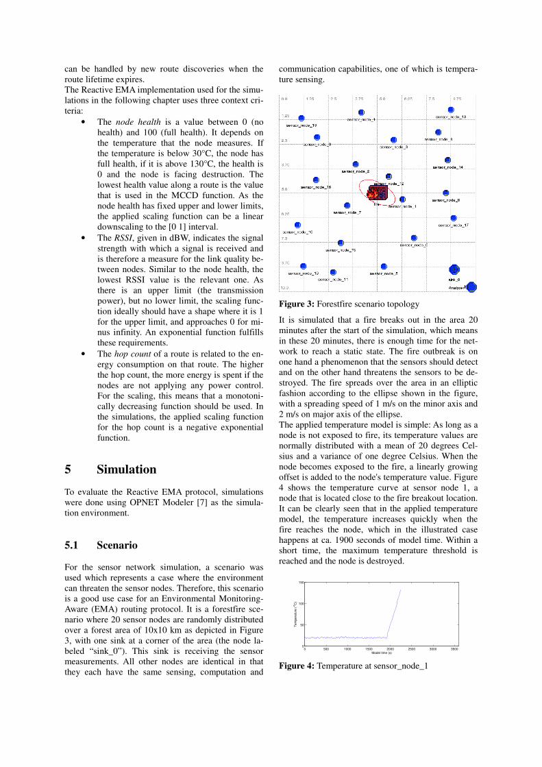
For the sensor network simulation, a scenario was
used which represents a case where the environment
can threaten the sensor nodes. Therefore, this scenario
is a good use case for an Environmental Monitoring-
Aware (EMA) routing protocol. It is a forestfire sce-
nario where 20 sensor nodes are randomly distributed
over a forest area of 10x10 km as depicted in Figure
3, with one sink at a corner of the area (the node la-
beled “sink_0”). This sink is receiving the sensor
measurements. All other nodes are identical in that
they each have the same sensing, computation and
communication capabilities, one of which is tempera-
ture sensing.
Figure 3: Forestfire scenario topology
It is simulated that a fire breaks out in the area 20
minutes after the start of the simulation, which means
in these 20 minutes, there is enough time for the net-
work to reach a static state. The fire outbreak is on
one hand a phenomenon that the sensors should detect
and on the other hand threatens the sensors to be de-
stroyed. The fire spreads over the area in an elliptic
fashion according to the ellipse shown in the figure,
with a spreading speed of 1 m/s on the minor axis and
2 m/s on major axis of the ellipse.
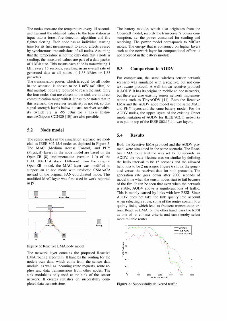
The applied temperature model is simple: As long as a
node is not exposed to fire, its temperature values are
normally distributed with a mean of 20 degrees Cel-
sius and a variance of one degree Celsius. When the
node becomes exposed to the fire, a linearly growing
offset is added to the node's temperature value. Figure
4 shows the temperature curve at sensor node 1, a
node that is located close to the fire breakout location.
It can be clearly seen that in the applied temperature
model, the temperature increases quickly when the
fire reaches the node, which in the illustrated case
happens at ca. 1900 seconds of model time. Within a
short time, the maximum temperature threshold is
reached and the node is destroyed.
0 500 1000 1500 2000 2500 3000 35000
50
100
150
Model time (s)
Te
mp
era
ture
( o
C)
Figure 4: Temperature at sensor_node_1
The nodes measure the temperature every 15 seconds
and transmit the obtained values to the base station as
input into a forest fire detection algorithm and fire
fighter alerting. Each node has an individual starting
time for its first measurement to avoid effects caused
by synchronous transmissions of all nodes. Assuming
that the temperature is not the only data that a node is
sending, the measured values are part of a data packet
of 1 kBit size. This means each node is transmitting 1
kBit every 15 seconds, resulting in an overall rate of
generated data at all nodes of 1.33 kBit/s or 1.33
packets/s.
The transmission power, which is equal for all nodes
in the scenario, is chosen to be 1 mW (=0 dBm) so
that multiple hops are required to reach the sink. Only
the four nodes that are closest to the sink are in direct
communication range with it. It has to be noted that in
this scenario, the receiver sensitivity is not set, so that
signal strength levels below a usual receiver sensitiv-
ity (which e.g. is -95 dBm for a Texas Instru-
ments/Chipcon CC2420 [10]) are also possible.
5.2 Node model
The sensor nodes in the simulation scenario are mod-
eled as IEEE 802.15.4 nodes as depicted in Figure 5.
The MAC (Medium Access Control) and PHY
(Physical) layers in the node model are based on the
Open-ZB [8] implementation (version 1.0) of the
IEEE 802.15.4 stack. Different from the original
Open-ZB model, the MAC layer was modified to
support an ad-hoc mode with unslotted CSMA/CA
instead of the original PAN-coordinated mode. This
modified MAC layer was first used in work reported
in [9].
Figure 5: Reactive EMA node model
The network layer contains the proposed Reactive
EMA routing algorithm. It handles the routing for the
node’s own data, which come from the sensor_data
module, as well as incoming route requests, route re-
plies and data transmissions from other nodes. The
sink module is only used at the sink of the sensor
network. It creates statistics on successfully com-
pleted data transmissions.
The battery module, which also originates from the
Open-ZB model, records the transceiver’s power con-
sumption, i.e. the power consumed for sending and
receiving. The power model corresponds to MICAz
motes. The energy that is consumed on higher layers
such as the network layer for computational efforts is
not recorded in the battery module.
5.3 Comparison to AODV
For comparison, the same wireless sensor network
scenario was simulated with a reactive, but not con-
text-aware protocol. A well-known reactive protocol
is AODV. It has its origins in mobile ad hoc networks,
but there are also existing sensor network implemen-
tations such as TinyAODV [11]. Both the Reactive
EMA and the AODV node model use the same MAC
and PHY layers and the same battery model. For the
AODV nodes, the upper layers of the existing Opnet
implementation of AODV for IEEE 802.11 networks
was put on top of the IEEE 802.15.4 lower layers.
5.4 Results
Both the Reactive EMA protocol and the AODV pro-
tocol were simulated in the same scenario. The Reac-
tive EMA route lifetime was set to 30 seconds, in
AODV, the route lifetime was set similar by defining
the hello interval to be 15 seconds and the allowed
hello loss to be 2 messages. Figure 6 shows the gener-
ated versus the received data for both protocols. The
generation rate goes down after 2000 seconds of
model time when the sensor nodes start to fail because
of the fire. It can be seen that even when the network
is stable, AODV shows a significant loss of traffic.
This is mainly caused by links with low RSSI: Since
AODV does not take the link quality into account
when selecting a route, some of the routes contain low
quality links, which lead to frequent transmission er-
rors. Reactive EMA, on the other hand, uses the RSSI
as one of its context criteria and can thereby select
more reliable routes.
Figure 6: Successfully delivered traffic
The two significant drops of the delivery rate are
caused by the failure of important relay nodes. The
first drop around t=3800s is the almost simultaneous
failure of sensor_node_6 and sensor_node_17, after
which the nodes in the upper right part of the area
cannot reach the sink any more. The second drop is
the failure of sensor_node_5, which was the last node
that provided connectivity to the sink.
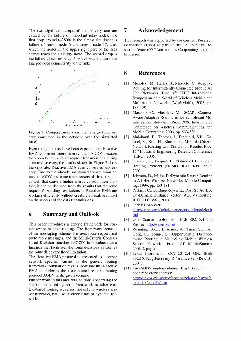
Figure 7: Comparison of consumed energy (total en-
ergy consumed in the network over the simulated
time)
Even though it may have been expected that Reactive
EMA consumes more energy than AODV because
there can be more route request transmissions during
a route discovery, the results shown in Figure 7 show
the opposite: Reactive EMA even consumes less en-
ergy. Due to the already mentioned transmission er-
rors in AODV, there are more retransmission attempts
as well that cause a higher energy consumption. Fur-
ther, it can be deduced from the results that the route
request forwarding restrictions in Reactive EMA are
working efficiently without creating a negative impact
on the success of the data transmissions.
6 Summary and Outlook
This paper introduces a generic framework for con-
text-aware reactive routing. The framework consists
of the messaging scheme that uses route request and
route reply messages, and the Multi-Criteria Context-
based Decision function (MCCD) is introduced as a
function that facilitates the route decisions as well as
the route discovery flood limitation.
The Reactive EMA protocol is presented as a sensor
network specific variant of the generic routing
framework. Simulation results show that this Reactive
EMA outperforms the conventional reactive routing
protocol AODV in the given scenario.
Further work in this area will be done concerning the
application of this generic framework to other con-
text-based routing scenarios, not only in wireless sen-
sor networks, but also in other kinds of dynamic net-
works.
7 Acknowledgement
This research was supported by the German Research
Foundation (DFG) as part of the Collaborative Re-
search Centre 637 “Autonomous Cooperating Logistic
Processes”.
8 References
[1] Musolesi, M., Hailes, S., Mascolo, C.: Adaptive
Routing for Intermittently Connected Mobile Ad
Hoc Networks. Proc. 6th
IEEE International
Symposium on a World of Wireless Mobile and
Multimedia Networks (WoWMoM), 2005, pp.
183-189.
[2] Mascolo, C., Musolesi, M.: SCAR: Context-
Aware Adaptive Routing in Delay Tolerant Mo-
bile Sensor Networks. Proc. 2006 International
Conference on Wireless Communications and
Mobile Computing, 2006, pp. 533-538.
[3] Malakooti, B., Thomas, I., Tanguturi, S.K., Ga-
jurel, S., Kim, H., Bhasin, K.: Multiple Criteria
Network Routing with Simulation Results. Proc.
15th
Industrial Engineering Research Conference
(IERC), 2006.
[4] Clausen, T., Jacquet, P.: Optimized Link State
Routing Protocol (OLSR). IETF RFC 3626,
2003.
[5] Johnson, D., Maltz, D.:Dynamic Source Routing
in Ad Hoc Wireless Networks. Mobile Comput-
ing, 1996, pp. 153-181.
[6] Perkins, C., Belding-Royer, E., Das, S.: Ad Hoc
On-Demand Distance Vector (AODV) Routing.
IETF RFC 3561, 2003.
[7] OPNET Modeler.
http://opnet.com/solutions/network_rd/modeler.h
tml
[8] Open-Source Toolset for IEEE 802.15.4 and
ZigBee. http://open-zb.net
[9] Wenning, B.-L., Lukosius, A., Timm-Giel, A.,
Görg, C., Tomic, S.: Opportunistic Distance-
aware Routing in Multi-Sink Mobile Wireless
Sensor Networks. Proc. ICT MobileSummit
2008, 8 pages.
[10] Texas Instruments: CC2420 2.4 GHz IEEE
802.15.4/ZigBee-ready RF transceiver (Rev. B),
2007.
[11] TinyAODV implementation. TinyOS source
code repository address:
http://tinyos.cvs.sourceforge.net/viewvc/tinyos/ti
nyos-1.x/contrib/hsn/.