a generic user interface architecture for analyzing use...
TRANSCRIPT
EPSRC Programme Grant EP/G059063/1
Public Paper no. 211
A generic user interface architecture for analyzing use hazards in infusion pump software
Paolo Masci, Yi Zhang, Paul Jones, Harold Thimbleby & Paul Curzon
Masci, P., Zhang, Y., Jones, P., Thimbleby, H., & Curzon, P.
(2014). A generic user interface architecture for analyzing use hazards in infusion pump software. Proceedings of the 5th
Workshop on Medical Cyber-Physical Systems (MCPS 2014), 1–14. OASIcs: Open Access Series in Informatics, vol. 36.
PP release date: 28 March 2014
file: WP211.pdf
A Generic User Interface Architecture forAnalyzing Use Hazards in Infusion Pump SoftwarePaolo Masci1, Yi Zhang2, Paul Jones2, Harold Thimbleby3, andPaul Curzon1
1 Queen Mary University of LondonLondon, United Kingdom{p.m.masci,p.curzon}@qmul.ac.uk
2 Center for Devices and Radiological HealthU.S. Food and Drug Administration, Silver Spring, MD, USA{yi.zhang2,paul.jones}@fda.hhs.gov
3 College of Science, Swansea UniversitySwansea, Wales, United [email protected]
AbstractThis paper presents a generic infusion pump user interface (GIP-UI) architecture that intendsto capture the common characteristics and functionalities of interactive software incorporated inbroad classes of infusion pumps. It is designed to facilitate the identification of use hazards andtheir causes in infusion pump designs. This architecture constitutes our first e�ort at establishinga model-based risk analysis methodology that helps manufacturers identify and mitigate usehazards in their products at early stages of the development life-cycle.
The applicability of the GIP-UI architecture has been confirmed in a hazard analysis focusingon the number entry software of existing infusion pumps, in which the GIP-UI architecture isused to identify a substantial set of user interface design errors that may contribute to use hazardsfound in infusion pump incidents.
1998 ACM Subject Classification K.6.1 Systems Analysis and Design, H.5.2 User Interfaces,D.2.11 Software Architectures
Keywords and phrases Infusion Pump, Hazard Analysis, Use Hazards, User Interface, Interact-ive Software, Design Errors
Digital Object Identifier 10.4230/OASIcs.MCPS.2014.1
1 Introduction
Infusion pumps are a class of medical devices widely used in various clinical settings to deliverfluids (including medication and nutrients) into a patient’s body in a controlled (prescribed)manner. The safety of infusion pumps, however, has been one of the top concerns in healthcare for a number of years [7]. For example, during the period from 2005 to 2009, 87 recallsassociated with infusion pumps were reported in US due to defective design or manufacturingproblems [8]. Through the analysis of incidents involving infusion pumps, medical deviceregulators such as the US Food and Drug Administration (FDA) concluded that two of themajor factors contributing to infusion pump failures were software defects and user interfaceissues [33].
Many user interface issues can be associated with software problems. For instance,a key bounce may be caused by a defect in the interrupt-handling code, and problems
© Paolo Masci, Yi Zhang, Paul Jones, Harold Thimbleby, and Paul Curzon;licensed under Creative Commons License CC-BY
Medical Cyber Physical Systems – Medical Device Interoperability, Safety, and Security Assurance (MCPS’14).Editors: Volker Turau, Marta Kwiatkowska, Rahul Mangharam, and Christoph Weyer; pp. 1–14
OpenAccess Series in InformaticsSchloss Dagstuhl – Leibniz-Zentrum für Informatik, Dagstuhl Publishing, Germany
2 User Interface Architecture for Analyzing Use Hazards in Infusion Pump Software
related to configuring the pump may be caused by inappropriate user-device interactionlogic. However, there are also user interface issues that have roots in the software engineeringprocess. For example, user interface problems may arise if the device’s interaction behavioris inconsistent with its user manual or labeling. Either type of user interface issues can a�ectthe device operation and hence a�ect patient safety. To help reduce or eliminate these issues,a systematic risk management process should be carried out.
ISO14971:2007 is a standard that provides a systematic risk management process formedical devices. In brief, it consists of five distinct activities. First, a hazard analysis isperformed to identify all known and foreseeable hazards and their causes, where a hazard isdefined as a potential source of physical injury or damage to people or environment. Second,risk estimation is performed to assess the probability of occurrence and severity of harm ofeach hazard, the combination of which is defined as risk. Third, risk evaluation is conductedto decide if every identified risk is acceptable based on pre-defined acceptability criteria.Fourth, if a risk is decided as unacceptable, control measures are designed and implementedto eliminate it or to mitigate it to an acceptable level. Finally, verification and validationactivities are conducted to ensure that the designed control measures are e�ective. Thesefive activities iterate and interleave until the device’s overall residual risk after mitigation isacceptable.
In the ISO14971 risk management process, the identification of hazards constitutes thefirst step and provides the basis for subsequent activities. In our previous work [10, 36], weillustrated the benefits of using a Generic Infusion Pump (GIP) architecture to support asystematic hazard analysis early in the design process. The GIP architecture, which capturescommon characteristics and functionalities of broad classes of infusion pumps, serves as areference ’standard’ for reasoning about hazards and potential causal factors in infusionpump designs.
In this paper, we present an e�ort that extends our previous work focusing on the userinterface design and its associated use hazards. In particular, we extend the GIP architecturewith more details that reflect common user-device interaction designs in existing infusionpumps. This serves to establish a foundation for reasoning about use hazards in infusionpumps and their contributing factors rooted in defective interaction (software) design.
Contributions. The contributions of this paper are as follows: (i) a Generic Infusion PumpUser Interface (GIP-UI) architecture is presented that can be used to reason about designdefects in infusion pump user interface software that may potentially cause use hazards; (ii)an analysis of infusion pump incident reports and other information sources is presented thatsummarizes the common use hazards in infusion pumps on the market related to numberentry tasks; and (iii) a preliminary hazard analysis that uses the GIP-UI to identify andreason about design errors commonly present in infusion pump number entry software andtheir relation to use hazards.
It is worth noting that the use hazards considered in this work, as well as software designdefects that cause these hazards, are common in other interactive medical devices (e.g.,ventilators) that have similar number entry systems. Therefore, we believe that the GIP-UIarchitecture may also be useful to the hazard analysis on these devices.
Organization. Section 2 presents background information about the GIP reference model.Section 3 elaborates the details of the GIP-UI architecture. Section 4 demonstrates howthe GIP-UI architecture can be used to facilitate the analysis of use hazards related to userinterface (in particular, the number entry software of a user interface). Section 5 comparesour work with other related work. Finally, Section 6 concludes the paper.
P. Masci, Y. Zhang, P. Jones, H. Thimbleby, and P. Curzon 3
2 Background: the Generic Infusion Pump model
The GIP model is a safety reference model for infusion pumps that captures the commonfunctionalities of modern infusion pumps. Figure 2 illustrates an abstract architecture of theGIP model, and the functionalities of each of its components are follows:
The GIP controller represents an abstraction of the pump software that manages theoverall infusion process and supervises interaction among all GIP components. It is responsiblefor instructing the pumping mechanism to deliver fluid as prescribed, as well as detectingand reporting alarm and warning conditions.
The GIP user interface (GIP-UI) represents an abstraction of the device elements(hardware and software) that enable interaction with the user. That is, the user canenter data (e.g., infusion parameters and pump settings) and control pump operation (e.g.,start/stop infusion). The user can also receive from the user interface feedback on the pumpand infusion status.
The device data recorder represents an abstraction of the logging mechanism used torecord the pump’s operational history (such as critical data and important events) to facilitateproblem diagnosis.
The fluid pathway represents an abstraction of the following elements: fluid reservoir,which stores the fluid to be delivered; infusion set, which is usually an IV needle; and deliveryinterface, which is a tube that connects the fluid reservoir to the infusion set.
A more detailed description of the GIP model can be found in [10, 36].
3 GIP User Interface (GIP-UI)
The GIP model was originally designed to provide a basis for analyzing the safety andcorrectness of the software control logic in infusion pumps. It had a simple means forinput/output, and therefore lacks any design or engineering details on user interface design.The GIP-UI architecture, depicted in Figure 1, replaces this user interface part with newarchitectural details, in order to establish a basis for reasoning about use hazards and interfacedesign errors in infusion pumps.
One important principle in the GIP-UI architecture is to enforce a clear separationbetween high-level functionalities of user interactions and low-level functionalities thatenable communication among its components (e.g., user interface elements that translateelectrical signals into logical events). Moreover, issues associated with user manuals and useenvironment are also considered to enable a more comprehensive (hazard) analysis of userinterface design.
The role of each component in the GIP-UI architecture is defined as follows.
GIP-UI widgets. This component represents an abstraction of the mechanical and hardwareelements of user interface that enable pump-user interaction. Widgets can be either inputor output widgets. Examples of input widgets include buttons, switches, and knobs, whileexamples of output widgets are displays, alarms, LED lights.
GIP-UI Software. This component represents an abstraction of the software regulating allfunctionalities of the user interface. It translates the user input received from the inputwidgets to commands understandable by the pump control software, manages interactivetasks such as number entry, and manages the output widgets to provide feedback (such asalarms and infusion status) to the user.
MCPS’14

4 User Interface Architecture for Analyzing Use Hazards in Infusion Pump Software
Figure 1 Logic architecture of the GIP user interface (GIP-UI). Labeled boxes represent an
abstraction of functional components of the system. Arrows between components represent flows of
information, user actions, or mechanical force between components. Dashed lines represent optional
components and information flows.
The GIP-UI Software includes the following logic modules:Core Modules. These software modules define the interactive behavior of the device, i.e.,how the pump responds to input events and how the device’s operational state is updatedas a consequence of input events. Input events are either from the user (labeled as ’useractions’ in Figure 1) or from the pump control software (as abstracted as GIP Controllerin Figure 2). The events from the GIP Controller are labeled as ’mission events’ and’status data’ in Figure 1).The internal structure of the Core Modules is an instantiation of the well-known Model-View-Controller (MVC) [16] architectural pattern. The MVC pattern is chosen because itpromotes a clear separation among di�erent aspects of a user interface’s core functionalities:defines the logic of interactions, decides what output information to be sent to the user,and decides how the output information is presented to the user. The Core Modulesconsist of:
The Interaction Logic , which represents an abstraction of the routines for handlinguser input events and forwarding them to the pump control software. These routinesdefine: (i) input key sequences needed to interact with the device, and correspondingalgorithms for processing input key sequences, and (ii) the communication protocolwith the pump control software.The Output Status Manager , an abstraction of the routines that specify feedbackinformation, i.e., what feedback is presented to the user.The Renderer , an abstraction of the routines for rendering feedback information onoutput widgets, i.e., how feedback is presented to the user.The Non-standard Input Interpreter , which represents an abstraction of the routinesfor managing input widgets that are more complex than keypads or mechanicalbuttons. Examples of the non-standard input widgets include touchscreens or gesturerecognition systems. For these input widgets, additional computation is needed tocorrectly interpret the user inputs. For example, in touchscreens, user gestures identify

P. Masci, Y. Zhang, P. Jones, H. Thimbleby, and P. Curzon 5
Figure 2 Logic architecture of the GIP. Labeled boxes represent an abstraction of functional
components of the system, and arrows represent flows of information (e.g., software commands,
hardware signals), user actions, or mechanical force between components. Note: Patient may overlap
with User for some types of infusion pumps.
just coordinates on the screen, and further processing is needed to associate the screencoordinates to the user action (on the input widgets rendered on the screen)1.
Drivers. These software modules translate digital signals received from Input Widgetsinto events that can be processed by the GIP-UI Core Modules, or translate output eventsinstructed by the Core Modules into output signals that Output Widgets can understandand produce output accordingly. The input events from the Drivers can be divided intotwo types: standard or non-standard. Standard events are generated during interactionswith classical mechanical input devices such as mechanical buttons. An example of astandard event is a button click. Non-standard events, on the other hand, are generatedduring interactions with input elements such as soft buttons or voice recognition systems.
GIP-UI Manuals. This component represents an abstraction of the reference materialaccompanying the pump, e.g., user manual and training material. Such material is part ofthe user knowledge and is therefore useful for identifying potential use hazards.
User. This models the characteristics of the intended user population. Examples of usercharacteristics include: user training level, cognitive and physical abilities, attitudes andbehaviors. Note that the user can be the patient or her family members for certain devices,and hence may not be trained nor be an experienced operator.
Use Environment. This component abstracts the physical environment in which the pumpis used. Environmental factors such as ambient light conditions can a�ect the device’sinteraction with the user and thus should be included into considerations during userinterface design. In Figure 1, arrows between the use environment and other componentsindicate what part of the system can be a�ected by the use environment. For example,inappropriate temperature levels may a�ect the physical abilities of patients and users, or gobeyond the operating temperature of the device itself.
1See [6] for a detailed illustration of the function of this module.
MCPS’14
6 User Interface Architecture for Analyzing Use Hazards in Infusion Pump Software
4 Validation of the GIP-UI architecture
The GIP-UI architecture explicitly defines how the device interacts with the user. Thus,it can be used as a basis to examine where and how the device incorrectly interacts withthe user, which may a�ect the device’s expected operation and ultimately create potentialhazards. This makes it easier to identify potential use hazards, or to cross-check the identifieduse hazards to ensure that no important hazards be missed.
More importantly, we believe:
Having a generic GIP-UI architecture facilitates the identification of common designdefects in user interface designs and provides insight into the cause-e�ect relationshipbetween these defects and infusion pump use hazards.
To prove the above hypothesis, we conducted a preliminary hazard analysis (PHA) usingthe GIP-UI architecture to 1) identify a set of common use hazards in infusion pumps relatedto number entry tasks and 2) to reason about the common design errors in user interfacesoftware that may contribute to these use hazards.
4.1 Hazard analysis based on the GIP-UIOur PHA focuses on the number entry part of the infusion pump interface. The numberentry software in an infusion pump is responsible for managing interaction with the userwhen infusion parameters or pump settings need to be configured. This is chosen as thefocus of our PHA because it is critical to infusion pump safety, in the sense that designerrors in it can cause use errors (e.g., mis-programming of the pump) with potentially severeconsequences to the patient (typically, overinfusion or underinfusion).
Our PHA of the number entry part follows a top-down approach: it starts from postulatedundesired system outcomes, and then works out the causes of the postulated outcomes atthe system design level. In the analysis, undesired system outcomes are given by use hazardsdocumented in infusion pump incident reports, including FDA Adverse Event reports.
4.1.1 Scope of the analysisNumber entry software is designed to support a number entry task, which identifies thesequence of actions carried out by the user when entering infusion parameters or pumpsettings. In the current generation of infusion pumps, the typical number entry task is carriedout through the following three main actions:1. An infusion parameter or pump setting is selected by the user2. The selected item is edited by the user3. The value is submitted by the user
The actions described above generally involve pressing buttons and keys on the pumpuser interface. Whenever the pump registers a button press or a key press, the number entrysoftware performs a computation. The computation may modify the device state (e.g., a newinfusion rate may be configured in the pump), and generate feedback on the user interface topresent the new device state to the user.
Buttons and keys currently used for number entry can be described using two broadclasses of widgets: serial number entry widgets, which allow the user to enter the digits ofthe values serially from the most significant to the least significant digit, and incrementalnumber entry widgets, which allow the user to modify an initial value by incrementingor decrementing it. Serial interfaces require a full numeric keypad, whereas incremental
P. Masci, Y. Zhang, P. Jones, H. Thimbleby, and P. Curzon 7
interfaces typically have two or four arrow keys (depending on the exact style of interaction).A detailed description of these number entry widgets is in [3]. Notable for hazard analysis ishow entry errors can be corrected. In a serial interface, either numbers have to be re-enteredor there must be a delete key. In contrast, in incremental interfaces, the whole point of theuser interface is to adjust numbers, so correcting errors does not require a separate deletekey, as correction is just a special case of adjustment.
4.2 Sources of informationThe analysis is informed by the following sources of information:
Domain knowledge developed within the CHI+MED project (www.chi-med.ac.uk). Thisknowledge results from the analysis of commercial infusion pumps [11, 12, 19, 22, 23, 24,27], infusion pump logs [17], incidents involving infusion pumps [13, 20, 21, 31], currentand best clinical practice in hospitals and home care [29], and workshops with pumpmanufacturers, users and clinicians [4, 5];Adverse event reports collected through the FDA’s Manufacturer and User Facility DeviceExperience (MAUDE) database [34];Recommendations on infusion pump design [25];Previous hazard analysis on other components of the GIP [10, 36];International standards ANSI/AAMI HE75:2009 on human factors, and ISO 14971:2007on risk management.
4.3 Hazard analysis resultsUsing the GIP-UI our PHA identified 60 potential design errors in number entry softwarethat may cause use hazards. From the GIP-UI perspective, these design errors arise fromindividual components in the architecture, from a combination of these components, or fromthe communication (i.e., information flow) between these components. The full table is inthe technical report [28].
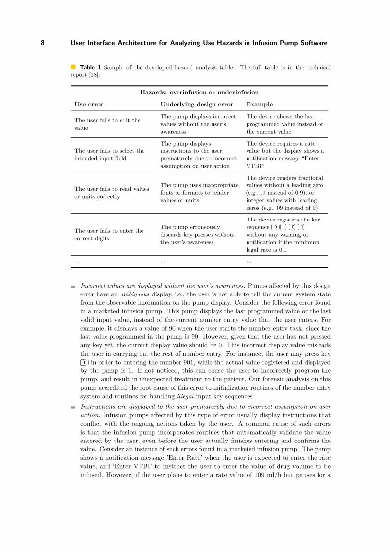
Table 1 is a sample of this hazard analysis table. The table shows the consideredhazards at the top: over-infusion (or under-infusion) where the patient receives more (or less)drug/nutrients than prescribed. Each row in the table identifies a use error that can leadto the over-/under-infusion hazards, as well as an underlying design error in infusion pumpsoftware that can cause this use error. A concrete example (as found in incident reports orour previous study) is also presented for each identified issue, to help understand the natureof the corresponding issue.
For illustrative purposes, we present design errors found to be commonly present innumber entry software of infusion pumps currently on the market. These design errors werefound in real marketed devices and may lead to severe clinical consequences, as they canpotentially lead to situations where the pump is erroneously programmed with incorrectinfusion parameters or pump settings without the user’s awareness.
4.3.1 Potential design errors in Output Status ManagerDesign errors in the Output Status Manager generally lead to inappropriate, inaccurate, orincorrect feedback to the user. As a result, the user may not be able to receive adequateinformation on the system’s status, what user action has actually been registered, and whatresult has been accomplished. Common instances of this type of design errors are as follows:
MCPS’14
8 User Interface Architecture for Analyzing Use Hazards in Infusion Pump Software
Table 1 Sample of the developed hazard analysis table. The full table is in the technical
report [28].
Hazards: overinfusion or underinfusion
Use error Underlying design error Example
The user fails to edit the
value
The pump displays incorrect
values without the user’s
awareness
The device shows the last
programmed value instead of
the current value
The user fails to select the
intended input field
The pump displays
instructions to the user
prematurely due to incorrect
assumption on user action
The device requires a rate
value but the display shows a
notification message “Enter
VTBI”
The user fails to read values
or units correctly
The pump uses inappropriate
fonts or formats to render
values or units
The device renders fractional
values without a leading zero
(e.g., .9 instead of 0.9), or
integer values with leading
zeros (e.g., 09 instead of 9)
The user fails to enter the
correct digits
The pump erroneously
discards key presses without
the user’s awareness
The device registers the key
sequence
⇤ �0⇥ � ⇤ �
.⇥ � ⇤ �0⇥ � ⇤ �
1⇥ �without any warning or
notification if the minimum
legal rate is 0.1
... ... ...
Incorrect values are displayed without the user’s awareness. Pumps a�ected by this designerror have an ambiguous display, i.e., the user is not able to tell the current system statefrom the observable information on the pump display. Consider the following error foundin a marketed infusion pump. This pump displays the last programmed value or the lastvalid input value, instead of the current number entry value that the user enters. Forexample, it displays a value of 90 when the user starts the number entry task, since thelast value programmed in the pump is 90. However, given that the user has not pressedany key yet, the current display value should be 0. This incorrect display value misleadsthe user in carrying out the rest of number entry. For instance, the user may press key⇤ �
1⇥ � in order to entering the number 901, while the actual value registered and displayedby the pump is 1. If not noticed, this can cause the user to incorrectly program thepump, and result in unexpected treatment to the patient. Our forensic analysis on thispump accredited the root cause of this error to initialization routines of the number entrysystem and routines for handling illegal input key sequences.Instructions are displayed to the user prematurely due to incorrect assumption on useraction. Infusion pumps a�ected by this type of error usually display instructions thatconflict with the ongoing actions taken by the user. A common cause of such errorsis that the infusion pump incorporates routines that automatically validate the valueentered by the user, even before the user actually finishes entering and confirms thevalue. Consider an instance of such errors found in a marketed infusion pump. The pumpshows a notification message ’Enter Rate’ when the user is expected to enter the ratevalue, and ’Enter VTBI’ to instruct the user to enter the value of drug volume to beinfused. However, if the user plans to enter a rate value of 109 ml/h but pauses for a

P. Masci, Y. Zhang, P. Jones, H. Thimbleby, and P. Curzon 9
second after entering⇤ �
1⇥ � ⇤ �0⇥ �, the pump erroneously makes an assumption that the user
has finished entering the rate, registers the entered value as 10, and displays the message’Enter VTBI’ to prompt the user to enter the drug volume to be infused. In other words,design errors of this kind may cause mode confusion to the user: the users thinks thepump is in mode x (in this case, x is entering the rate) while it is actually in mode y (inthis case, y is entering the volume to be infused). In fact, this type of error (’right data,wrong field’) appears to be the most common use errors documented in infusion pumpincident reports [8].
4.3.2 Potential design errors in RendererDesign errors in the Renderer module typically introduce visualization issues in the device.For example, the device renders information erroneously or inconsistently, or fails to makeappropriate display elements perceptible.
Inappropriate fonts or inappropriate formats are used to render numbers or units. Exampleproblems found in marketed devices include: fractional values are displayed without aleading zero (e.g., displaying .9 instead of 0.9); integer values are rendered with leadingzeros (e.g., 09 instead of 9); and small decimal point (e.g., the decimal point is rendered as· instead of •). Another example is with seven-segments displays [32]. Rendering valuesin seven-segment displays can easily cause the user to misread the values, as integer andfractional digits are hard to distinguish, and can result in out-by-ten errors.
Soft keys are incorrectly labeled without the user’s awareness. Soft keys are buttons thatcan be programmed to perform di�erent functions during the pump’s operation. Moderninfusion pump usually implement soft keys as hard buttons placed on the sides of thescreen, while soft button labels are displayed on the screen next to these hard buttons.We found it common for infusion pumps to display textual messages not intended tobe soft button labels next to hard buttons, creating the illusion that they were. It isalso common that infusion pumps erroneously render labels next to unused soft keys.Consider a pump with a soft key on the right of the screen, and another soft key on theleft. Assume that these soft keys are aligned. If the pump renders ’Rate’ aligned to thesoft key on the left, and “2 ml/h” aligned to the soft key on the right, which soft keyshould be used to select the rate? The reasonable a�ordance2 is that both soft keys beused for this purpose, as the two pieces of text are logically a single piece of information.The pump that we studied, however, disables one of these two keys, without providingany feedback when the user presses the disabled key. The likely clinical consequence ofsuch errors is delay of treatment.
4.3.3 Potential design errors in Interaction LogicDesign errors in the Interaction Logic module generally result in incorrect human-computerinteraction with buttons, keys, and displays. Typical causes of such errors include inappropri-ate or over-complicated procedures (i.e., sequence of actions) to interact with these widgetsor the failure of implementing mechanisms for preventing or detecting user errors duringinteraction. Common instances of design errors in Interaction Logic include:
2A�ordance is a property of objects that determines how the object can possibly be used [26].
MCPS’14
10 User Interface Architecture for Analyzing Use Hazards in Infusion Pump Software
Key presses by the user is erroneously discarded without the user’s awareness. Pumpsa�ected may unexpectedly discard key presses and commit an out-by-ten error, which canpotentially result in severe clinical consequences. For example, an infusion pump studiedby us 3 enforces the constraint that all infusion rate values must be greater than or equalto 0.1. Thus, its number entry routines discards the third key press in the key sequence⇤ �
0⇥ � ⇤ �.⇥ � ⇤ �
0⇥ � ⇤ �1⇥ �, as the value violates the constraint, and automatically sets the input rate
as the minimum valuate 0.1. Moreover, the pump enforces that no fractional numbersare allowed for value above or equal to 100. Thus, the decimal point key press in theinput sequence
⇤ �1⇥ � ⇤ �
0⇥ � ⇤ �0⇥ � ⇤ �
.⇥ � ⇤ �1⇥ � is discarded, and the erroneous value 1001 is registered.
No warning or notification is provided to the user in either of these two cases. The rootcause of this design error typically resides in the number entry routines for handlingillegal input values (e.g., out-of-range or ill-formed values).Values entered by the user are erroneously discarded without the user’s awareness. Pumpsa�ected by this design error unexpectedly discard the value entered by the user if theinput field is de-selected (e.g., the user selects another input field without confirming thisentered value). The following is an example detected in a marketed infusion pump: theuser first changes the infusion rate from its current value 91 mL per hour to 0.9 mL perhour, and then selects the VTBI field to edit without confirming the new infusion rate.As a result, the pump automatically discarded the new rate value and maintained theprevious value, without any notification or warning. Design errors like this can cause theuser to mistakenly configure the treatment to the patient, and result in serious clinicalconsequences.
4.3.4 Potential design errors in Non-standard Input InterpreterDesign errors in the Non-standard Input Interpreter generally result in human-machineinteraction issues with touch-screen displays. A device with such errors typically requiresthe user to take an inappropriate or over-complicated sequence of actions to interact withthe non-standard input widgets. It may also fail to implement necessary mechanisms toprevent user errors during the interaction. Common design errors in the Non-standard InputInterpreter include:
Legal gestures on touchscreens are erroneously discarded without the user’s awareness.Devices with this erroneous design may ignore legal gestures on input widgets. Forexample, slide gestures on scroll bars are erroneously ignored; press and hold gestureson virtual buttons and tap gestures on input fields are erroneously ignored. This designerror can be associated with number entry routines that activate or select touchscreeninput widgets. The likely consequence of this kind of errors is the delay of number entry.Similar gestures on touchscreens are erroneously associated with logically di�erent func-tions. Pumps a�ected by this design error erroneously execute functions not intended bythe user. This design error may be associated with number entry routines that activate orselect touchscreen input widgets, such as virtual buttons and input areas. The followingis an example error detected in a marketed pump. The user selected the infusion ratefield and plans to enter a value. However, the pump’s touchscreen registers a tap gestureoutside the area of the selected rate input field or outside the virtual buttons for numberentry, probably because the user accidentally taps outside the widgets or the touchscreen
3More information about this study can be found in [24].

P. Masci, Y. Zhang, P. Jones, H. Thimbleby, and P. Curzon 11
is mis-calibrated. Thus, the input field is automatically de-selected, without any warningor notification for the user. Notably, this design error may aggravate other design errorssuch as those in the Interaction Logic, as values may be mistakenly confirmed or discardedbecause of accidental touch on the touchscreen.
4.4 DiscussionAs shown in the PHA results, the GIP-UI architecture provides a basis for us to enumeratecommon errors in user interface design associated with number entry. It also facilitates theestablishment of the cause-e�ect relationship between these errors and the use hazards. Asdemonstrated in our PHA, this cause-e�ect relationship can help device developers maketheir hypotheses and assumptions explicit when reasoning about user interface behaviors, andthus enable clear thinking about possible causal factors. Ultimately, it can assist developersin designing e�ective mitigation measures to address use hazards and design errors causingthem.
The GIP-UI architecture and hazard analysis results presented in this paper can beused by manufacturers as an independent reference to challenge the safety of their own userinterface design. Alternatively, manufacturers can use our work as the starting point toperform more comprehensive hazard analysis on their products (in this case, manufacturersshould populate the GIP-UI architecture with design details specific to their products).
It is worth pointing out that, even though our PHA identified a substantial set of usehazards and their root causes 4, it is by no means exhaustive. In fact, a PHA is onlythe first round of hazard analysis applied to a design, and its results constitute an initialyet informative inventory for subsequent detailed hazard analysis or the initial design ofrisk mitigation measures. In order to identify all potential hazards (and related causes) incomplex systems, the best practice is to employ a combination of systematic hazard analysistechniques, such as Failure Mode and E�ect Analysis (FMEA) [9] or Systems-TheoreticAccident Modeling and Processes (STPA) [18], in a complementary manner [14].
5 Related work
Although there are many examples of conceptual/abstract architectures that can be used forhazard analysis, few of them are designed to support the identification of use hazards andtheir potential causal causes in medical devices.
In [2, 1], an architecture is developed for a STPA-based hazard analysis for a radiotherapysystem. The architecture describes the functions of five sub-systems of the Paul ScherrerInstitute’s experimental ProScan proton therapy system. Usability issues were considered inthe study. However, this architecture was not designed to explore potential causal factors ofuse hazards, and some information on usability issues were obtained through workshops withdomain experts. Similarly, in [30], a system architecture is developed for a STPA hazardanalysis of pacemakers. Even though pacemakers do not have a user interface, the analysisconsidered a wider, system-level perspective that included users and patients. Users aremodeled as ’human controllers’ guided by mental models. Use hazards, however, were not inthe scope of the analysis. The architecture presented in this paper can be used together withanalysis techniques such as STPA. It provides information that can be used as a basis to
4The full hazard tables are in [28].
MCPS’14
12 User Interface Architecture for Analyzing Use Hazards in Infusion Pump Software
populate the controller and controlled process components of the system architecture withdetails necessary to analyze the potential causes of use hazards.
In [15], design errors related to barcoded medication administration systems are explored.These systems are commonly used together with infusion pumps and other medical devices toidentify patients, clinicians, and drugs. The analysis in [15] revealed how defective barcodingsystems encouraged workarounds that could potentially lead to severe clinical consequences.These results complement the results of our hazard analysis, in that they explore issues inthe design of an alternative number entry system that can be installed on infusion pumps.
Other works studying use hazards in medical devices usually overlook design issues. Forinstance, in [35], training and clinical procedures are identified as potential causes of usehazards. Consider a use hazard where an incorrect patient profile is selected. The establishedcausal relationship identifies nurses being unclear about the available profiles, and thereforebetter training is suggested as a mitigating measure. Even though training and clinicalprocedures may be contributing factors of use hazards, this approach to hazard analysisprovides little or no insights about how an infusion pump can be (re-)designed to assuresafety under existing training and clinical procedures.
6 Conclusions
A generic user interface architecture, GIP-UI, has been presented to facilitate the identificationand reasoning of use hazards in infusion pumps. Its applicability to this end has beenconfirmed through a hazard analysis that involved known use hazards in marketed infusionpumps. The architecture was successfully used to reason about the cause-e�ect relationsbetween these hazards and their causes (i.e., software design errors) commonly present inuser interface designs.
The GIP-UI architecture can potentially be used as the basis for hazard analysis onuse hazards, and for the establishment of safety requirements that ensure reasonable safetyregarding device-user interaction. It is also worth noting that, even though the GIP-UI isdesigned for infusion pumps, the general idea behind it can be applied to other medicaldevices that rely on the same mechanism as defined in GIP-UI to interact with the users,and thus facilitate the assessment and assurance of their safety in device-user interaction.
Acknowledgment. This work is support by CHI+MED (Computer-Human Interaction forMedical Devices, EPSRC research grant [EP/G059063/1]). We thank Michael Harrison(Newcastle University) and Chris Vincent (University College London) for their valuablecomments that helped us to improve our manuscript.
References
1 B. Antoine. Systems Theoretic Hazard Analysis (STPA) applied to the risk review of com-plex systems: an example from the medical device industry. PhD thesis, MassachusettsInstitute of Technology, 2013.
2 A. Blandine, M. Rejzek, and C. Hilbes. Evaluation of stpa in the safety analysis of thegantry 2 proton radiation therapy system, 2012.
3 A. Cauchi, P. Curzon, P. Eslambolchilar, A. Gimblett, H. Huang, P. Lee, Y. Li, P. Masci,P. Oladimeji, R. Ruköenas, and H. Thimbleby. Towards dependable number entry formedical devices. In EICS4Med, 1st International Workshop on Engineering InteractiveComputing Systems for Medicine and Health Care. ACM Digital Library, 2011.
P. Masci, Y. Zhang, P. Jones, H. Thimbleby, and P. Curzon 13
4 CHI+MED. Guidelines for number entry interface design (infusion devices). http://www.chi-med.ac.uk/researchers/bibdetail.php?docID=684, 2013.
5 CHI+MED. Personas and scenarios (infusion devices). http://www.chi-med.ac.uk/researchers/bibdetail.php?docID=685, 2013.
6 S. Conversy, E. Barboni, D. Navarre, and P. Palanque. Improving modularity of interactivesoftware with the MDPC architecture. In EICS2007. ACM Digital Library, 2007.
7 ECRI Institute 2014 top 10 health technology hazards, 2014.8 Association for the Advancement of Medical Instrumentation. Infusing patients safely:
priority issues from the AAMI/FDA infusion device summit. http://www.aami.org/publications/summits/AAMI_FDA_Summit_Report.pdf, 2010.
9 P. L. Goddard. Software fmea techniques. In Reliability and Maintainability Symposium,2000. Proceedings. Annual, pages 118–123. IEEE, 2000.
10 The Generic Patient Controlled Analgesia Pump Hazard Analysis. http://rtg.cis.upenn.edu/gip-docs/Hazard_Analysis_GPCA.doc.
11 M. D. Harrison, J. Campos, and P. Masci. Reusing models and properties in the analysisof similar interactive devices. Innovations in Systems and Software Engineering, Springer-Verlag London, 2013.
12 M. D. Harrison, P. Masci, J. C. Campos, and P. Curzon. Automated theorem proving forthe systematic analysis of interactive systems. In 5th International Workshop on FormalMethods for Interactive Systems (FMIS2013), 2013.
13 ISMP Canada. Fluorouracil incident root cause analysis report. http://www.ismp-canada.org/download/reports/FluorouracilIncidentMay2007.pdf.
14 P. Jones, J. Jorgens III, A. R. Taylor Jr., and M. Weber. Risk management in the design ofmedical device software systems. Journal of Biomedical Instrumentation and Technology,36(4):237–266, 2002.
15 R. Koppel, T. Wetterneck, J. L. Telles, and B. Karsh. Workarounds to barcode medicationadministration systems: their occurrences, causes, and threats to patient safety. Journalof the American Medical Informatics Association, 15(4):408–423, 2008.
16 G. E. Krasner and S. T. Pope. A description of the Model-View-Controller user interfaceparadigm in the Smalltalk-80 system. Journal of object oriented programming, 1(3):26–49,1988.
17 P. Lee, F. Thompson, and H. Thimbleby. Analysis of infusion pump error logs and theirsignificance for health care. British Journal of Nursing, 21(8):S12–S22, 2012.
18 N.G. Leveson. Software challenges in achieving space safety. Journal of the British Inter-planetary Society, 2009.
19 P. Masci, A. Ayoub, P. Curzon, M. D. Harrison, I. Lee, and H. Thimbleby. Verification ofinteractive software for medical devices: Pca infusion pumps and fda regulation as an ex-ample. In EICS2013, 5th ACM SIGCHI Symposium on Engineering Interactive ComputingSystems. ACM Digital Library, 2013.
20 P. Masci and P. Curzon. Checking user-centred design principles in distributed cognitionmodels: a case study in the healthcare domain. In Proceedings of the 7th conference onWorkgroup Human-Computer Interaction and Usability Engineering of the Austrian Com-puter Society: information Quality in e-Health, USAB’11, pages 95–108, Berlin, Heidelberg,2011. Springer-Verlag.
21 P. Masci, H. Huang, P. Curzon, and M. D. Harrison. Using pvs to investigate incidentsthrough the lens of distributed cognition. In Alwyn E. Goodloe and Suzette Person, editors,Proceedings of the 4th NASA Formal Methods Symposium (NFM 2012), volume 7226, pages273–278, Berlin, Heidelberg, April 2012. Springer-Verlag.
MCPS’14
14 User Interface Architecture for Analyzing Use Hazards in Infusion Pump Software
22 P. Masci, R. Ruköenas, P. Oladimeji, A. Cauchi, A. Gimblett, Y. Li, P. Curzon, andH. Thimbleby. On formalising interactive number entry on infusion pumps. ECEASST, 45,2011.
23 P. Masci, R. Ruköenas, P. Oladimeji, A. Cauchi, A. Gimblett, Y. Li, P. Curzon, andH. Thimbleby. The benefits of formalising design guidelines: A case study on the pre-dictability of drug infusion pumps. Innovations in Systems and Software Engineering,Springer-Verlag London, 2013.
24 P. Masci, Y. Zhang, P. Jones, P. Curzon, and H. Thimbleby. Formal verification of medicaldevice user interfaces using PVS. In ETAPS/FASE2014, 17th International Conference onFundamental Approaches to Software Engineering. Springer Berlin Heidelberg, 2014.
25 National Patient Safety Agency (NHS/NPSA). Design for patient safety: A guide tothe design of electronic infusion devices. http://www.nrls.npsa.nhs.uk/resources/?EntryId45=68534, March 2010.
26 D. A. Norman. The design of everyday things. Basic books, 2002.27 P. Oladimeji, H. Thimbleby, and A. Cox. Number entry interfaces and their e�ects on error
detection. In Human-Computer Interaction – INTERACT 2011, volume 6949 of LectureNotes in Computer Science, pages 178–185. Springer Berlin Heidelberg, 2011.
28 P. Masci et al. A preliminary hazard analysis for the GIP number entry software. http://www.eecs.qmul.ac.uk/~masci/works/GIP-UI-PHA.pdf, 2014.
29 R. Ruköenas, P. Curzon, A. Blandford, and J. Back. Combining human error verificationand timing analysis: a case study on an infusion pump. Formal Aspects of Computing,pages 1–44, 2013.
30 Q. S. M. Song. A system theoretic approach to design safety into medical device. PhD thesis,Massachusetts Institute of Technology, 2012.
31 H. Thimbleby. Is it a dangerous prescription? BCS Interfaces, 84, 2010.32 H. Thimbleby. Reasons to question seven segment displays. In Proceedings ACM Conference
on Computer-Human Interaction — CHI 2013, pages 1431–1440. ACM, 2013.33 US Food and Drug Administration, Center for Devices and Radiological Health
(FDA/CRDH). White Paper: Infusion Pump Improvement Initiative, 2010.34 US Food and Drug Administration (FDA). Manufacturer and User Facility
Device Experience Database (MAUDE). http://www.fda.gov/MedicalDevices/DeviceRegulationandGuidance/PostmarketRequirements/ReportingAdverseEvents/ucm127891.htm.
35 T. B. Wetterneck, K. A. Skibinski, T. L. Roberts, S. M. Kleppin, M. E. Schroeder, M. Enloe,S. S. Rough, A. S. Hundt, and P. Carayon. Using failure mode and e�ects analysis toplan implementation of smart IV pump technology. American Journal of Health-SystemPharmacy, 63(16):1528–1538, 2006.
36 Y. Zhang, P. Jones, and R. Jetley. A hazard analysis for a generic insulin infusion pump.Journal of diabetes science and technology, 4(2):263, 2010.