a guide for: prelude led surgery light, c/us
TRANSCRIPT

Shor-Line | 800.444.1579 | shor-line.com
A guide for:
Prelude LED Surgery Light, C/US
Save This Guide For Future Reference
PN: 006.9138.01Updated: 04/22/16
To reduce the risk of injury, the user must read and understand this guide before installation of this product.
ATTENTION Pour réduire le risque de blessures, l'utilisateur doit lire et comprendre ce guide avant d'installer le produit.
This product is for animal use only. We do not condone this product for other uses.
ATTENTION Ce produit est destiné à un usage vétérinaire uniquement. Nous ne recommandons
pas l’utilisation de ce produit à d'autres fins.
E113714
Complies with AAMI ES60601-1CSA C22.2 No. 60601-1
Introduction
Thank you for purchasing Shor-Line products. As a leader in animal care equipment, our commitment to you is exactly the same as it was in 1927.
We hope this guide answers any questions you might have in regards to use, care or installation. If you can’t find the answers to your questions, have further questions or would like to purchase additional products, please contact us at 800.444.1579 or 913.281.1500. If in Europe phone +44 1446 77 20 41.
Consider keeping this guide in a safe and convenient place for future assistance.
IMPORTANT: DO NOT ATTEMPT TO DISASSEMBLE THE LIGHT OR ANY ASSOCIATED PRODUCT WITHOUT FIRST CONTACTING SHOR-LINE
For your safety, please follow the instructions on these labels:
This product is for animal use only. We do not condone this product for other uses.
To reduce the risk of injury, the user must read and understand this guide before installation of this product.
Your Surgery Table is heavy so precautions must be taken. Use two or more people when unpacking your shipment.
Tables shipped during cold weather should be allowed to warm up to room temperature before operating foot pump.
This product is for animal use only. We do not condone this product for other uses.
Shor-LineSchroer Manufacturing Company511 Osage Ave.Kansas City, Kansas 66105, USAphone 800.444.1579 fax 913.281.5339email [email protected] www.shor-line.com
Shor-Line LimitedVale Business ParkLlandow, Vale of Glamorgan CF71 7PFUnited Kingdomphone +44 1446 77 20 41 fax +44 1446 77 36 68email [email protected] www.shor-line.co.uk
2
It is required that installations and repair of your Prelude LED Light System be performed by a qualified electrician only. Failure to comply will result in a void of all Shor-Line warranties.
AVERTISSEMENT L'installation et la réparation de votre système d'éclairage Prelude à DEL doivent être effectuées par un électricien qualifié. Le non-respect de cette directive entraînera l'annulation de toutes les garanties de Shor-Line.

Shor-Line | 800.444.1579 | shor-line.com 3
Contents Section 1: Unpacking & Inspecting Shipment Unpacking & Inspecting Steps .................................................................................................................. 4 Prelude LED Surgery Lighting System Options ........................................................................................ 5 Parts List .................................................................................................................................................... 6
Section 2: Prelude LED Surgery Lighting System Technical Information LED Surgery Light Specifications .............................................................................................................. 6 Technical Drawings.................................................................................................................................... 8
Section 3: Single Ceiling Mount and Installation (Option 1) Pre-Installation Check ............................................................................................................................. 11 Installation of Single Ceiling Mount Arm Assembly ................................................................................ 14
Section 4: Dual Ceiling Mount and Installation (Option 2) Pre-Installation Check ............................................................................................................................. 16 Installation of Dual Ceiling Mount Arm Assembly .................................................................................. 19
Section 5: Wall Mount Light System and Installation (Option 3) Pre-Installation Check ............................................................................................................................. 21 Installation Wall Mount Assembly ........................................................................................................... 22 Installation Wall Mount Arm Assembly ................................................................................................... 24
Section 6: Mobile Light System and Installation (Option 4) Pre-Installation Check ............................................................................................................................. 26 Upright Post Assembly ............................................................................................................................ 27
Section 7: Light Head Assembly Light Head to Arm Assembly .................................................................................................................. 28 Section 8: Arm Assembly Adjustments Arm Assembly Adjustments .................................................................................................................... 30
Section 9: Functionality Shor-Line Prelude LED Light Functions ................................................................................................... 31
Section 10: LED Surgery Light Safety, Maintenance and Cleaning Safety Instructions ................................................................................................................................... 32 LED Light Maintenance ........................................................................................................................... 32 Cleaning .................................................................................................................................................. 32 Disposal of Waste ................................................................................................................................... 32 Care & Cleaning Best Practices ............................................................................................................... 33 Protecting Against Disease & Infection ................................................................................................... 33 Section 11: Services, Terms & Conditions and Warranty Terms & Conditions ................................................................................................................................. 34 Order & Acceptance ............................................................................................................................... 34 Entire Agreement .................................................................................................................................... 34 Terms Of Payment ................................................................................................................................... 34 Prices & Quotes ...................................................................................................................................... 34 Taxes ....................................................................................................................................................... 34 Deliveries ................................................................................................................................................ 34 Inspection ................................................................................................................................................ 34 Product Satisfaction ................................................................................................................................ 35 Limited Warranty ..................................................................................................................................... 35 Return Policy ........................................................................................................................................... 36 Indemnity ................................................................................................................................................ 36 Unlawful Use ........................................................................................................................................... 36 Regulations And Codes .......................................................................................................................... 36 Seller’s Remedies .................................................................................................................................... 36 Miscellaneous .......................................................................................................................................... 36
4
Section 1: Unpacking & Inspecting Shipment
Unpacking & Inspecting Steps
Step 1 Locate the Packing Slip that describes the parts and quantities shipped. Your Prelude LED Light should be carefully examined upon arrival for possible damage in shipment. If any damage is found, notify Shor-Line immediately.
Step 2 Review Section 11: Shor-Line’s Warranty Information. For more information visit: www.shor-line.com/warranty. Then click the Damages/Returns/Repairs link on the left.
Step 3Be sure that all parts are contained for your Light.
Step 4 Check content for concealed damage.
If Concealed Damage: Follow instructions within Section 11: Shor-Line’s Warranty Information. For more information visit:www.shor-line.com/warranty. Then click the Damages/Returns/Repairs link on the left. Call Shor-Line immediately so we can expedite replacements or repairs.IMPORTANT: After fifteen (15) calendar days of receipt of merchandise, this policy becomes void.
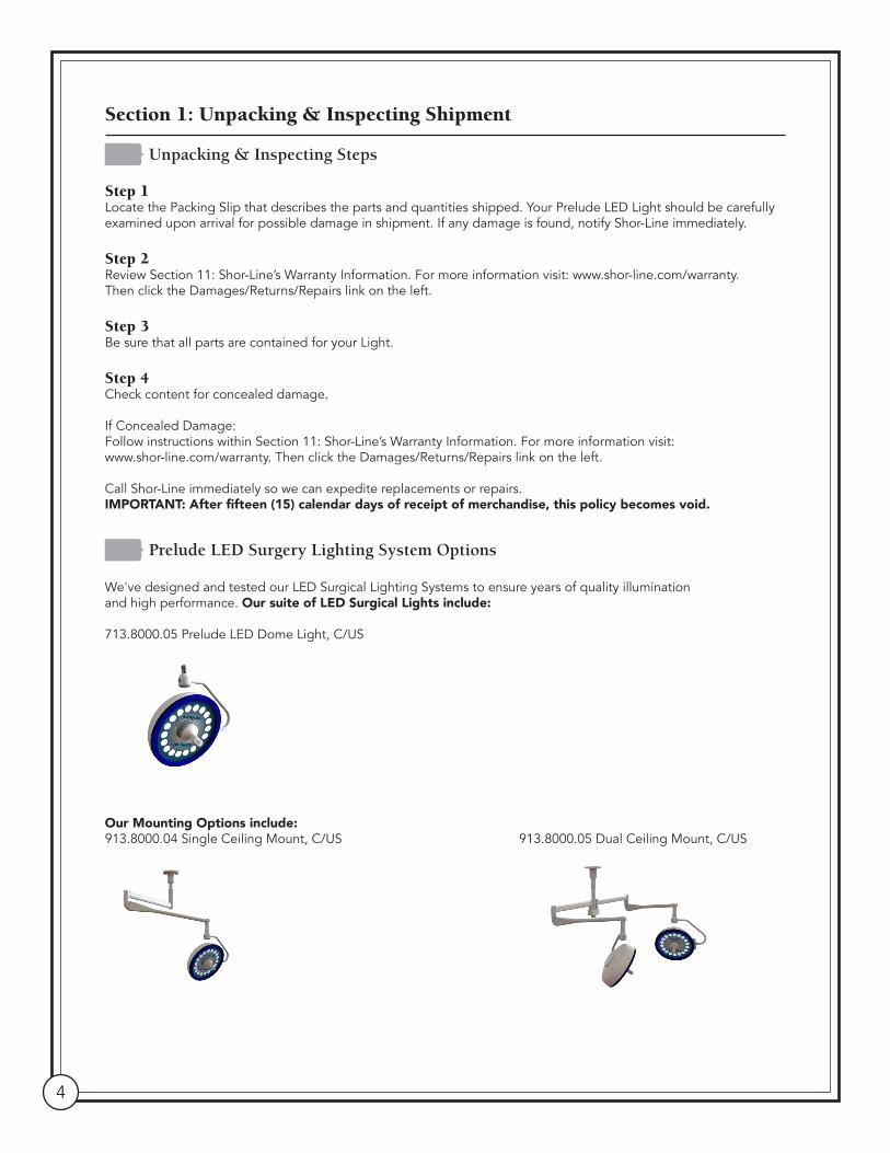
Prelude LED Surgery Lighting System Options
We've designed and tested our LED Surgical Lighting Systems to ensure years of quality illumination and high performance. Our suite of LED Surgical Lights include:
713.8000.05 Prelude LED Dome Light, C/US
Our Mounting Options include:913.8000.04 Single Ceiling Mount, C/US 913.8000.05 Dual Ceiling Mount, C/US
Shor-Line | 800.444.1579 | shor-line.com 5
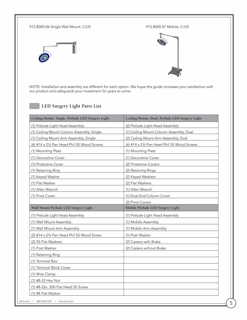
913.8000.06 Single Wall Mount, C/US 913.8000.07 Mobile, C/US
NOTE: Installation and assembly are different for each option. We hope this guide increases your satisfaction with our product and safeguards your investment for years to come.
LED Surgery Light Parts List Ceiling Mount, Single, Prelude LED Surgery Light Ceiling Mount, Dual, Prelude LED Surgery Light
(1) Prelude Light Head Assembly (2) Prelude Light Head Assembly
(1) Ceiling Mount Column Assembly, Single (1) Ceiling Mount Column Assembly, Dual
(1) Ceiling Mount Arm Assembly, Single (2) Ceiling Mount Arm Assembly, Dual
(6) #14 x 2½ Pan Head Phil SS Wood Screws (6) #14 x 2½ Pan Head Phil SS Wood Screws
(1) Mounting Plate (1) Mounting Plate
(1) Decorative Cover (1) Decorative Cover
(1) Protective Cover (2) Protective Covers
(1) Retaining Ring (2) Retaining Rings
(1) Keyed Washer (2) Keyed Washers
(1) Flat Washer (2) Flat Washers
(1) Allen Wrench (1) Allen Wrench
(1) Pivot Cover (1) Dual End Column Cover
(2) Pivot CoversWall Mount Prelude LED Surgery Light Mobile Prelude LED Surgery Light
(1) Prelude Light Head Assembly (1) Prelude Light Head Assembly
(1) Wall Mount Assembly (1) Mobile Assembly
(1) Wall Mount Arm Assembly (1) Mobile Arm Assembly
(2) #14 x 2½ Pan Head Phil SS Wood Screw (1) Post Washer
(2) SS Flat Washers (2) Casters with Brake
(1) Post Washer (2) Casters without Brake
(1) Retaining Ring
(1) Terminal Box
(1) Terminal Block Cover
(1) Wire Clamp
(1) #8-32 Hex Nut
(1) #8-32x .500 Flat Head SS Screw
(1) #8 Flat Washer

6
Section 2: Prelude LED Surgery Lighting System Technical Information
LED Surgery Light Specifications
Electrical One Light Head Only
Input Voltage/Current, Dome Light 120/240 VAC, 50/60 HZ, 1.0 A @120v/ .5A @ 240v
Optical (all measurements at 39 3/ 8" [one meter]) 18 White Light LEDs with individual parabolic reflectors
Central Illuminance (Ec) 100k LUX
Light Field Diameter (d10) 9.5" (242 mm)
Light Field Diameter (d50) 5.5" (142 mm) 50% of EC
Adjustable Dimming 40k LUX To 100k LUX
LED Life 75k+ Hours
Depth of Illumination 30.8" (782 mm)
Light Pattern 6" (152 mm)
Optical (continued)
Shadow DilutionRemaining illuminance at the bottom of a standardized tube (inside)Remaining illuminance at the bottom of a standardized tube when beam is obstructed by corresponding number of masks
0.0215% with One Mask; 0.0146% with Two Masks
94.1%0.0066% with One Mask0.0057% with Two Masks
Total Irradiance (Ee) 286.2 W/m2
Color Temperature 4500º K
CRI (Ra) 90
Specific Index (R9) 72Operational Environmental Conditions
Transport and Storage 4 to 122 Degrees Fahrenheit (-20 to 50°C)
Humidity 10-90% Relative Humidity
Atmospheric Pressure 97 kPa to 104 kPa
Mechanical - Weights Single Ceiling Mount Assembly
LED Light Head Assembly 12.2 lb (5.5 kg)
Single Ceiling Column Mount 32.0 lb (14.5 kg)
Extension Arm 7.0 lb (3.2 kg)
Spring Arm 13.7 lb (6.2 kg)
Total Single Ceiling Mount Assembly 64.9 lb (29.4 kg)
Mechanical - Weights Dual Ceiling Mount Assembly
LED Light Head Assembly x 2 24.4 lb (11.0 kg)
Dual Ceiling Column Mount 43.0 lb (19.6 kg)
Extension Arm x 2 14.0 lb (6.4 kg)
Spring Arm x 2 27.4 lb (12.4 kg)
Total Dual Ceiling Mount Assembly 108.8 lb (49.4 kg)

Shor-Line | 800.444.1579 | shor-line.com 7
Mechanical - Weights Wall Mount Assembly
LED Light Head Assembly 12.2 lb (5.5 kg)
Wall Bearing Weldment 8.0 lb (3.6 kg)
Extension Arm 7.0 lb (3.2 kg)
Spring Arm 13.7 lb (6.2 kg)
Total Wall Mount Assembly 40.9 lb (18.6 kg)
Mechanical - Weights Mobile Assembly
LED Light Head Assembly 12.2 lb (5.5 kg)
Arm 8.0 lb (3.6 kg)
Base 99.0 lb (44.9 kg)
Total Mobile Assembly 122.0 lb (55.0 kg)
Motion - Extension
Head Vertical Motion 47" (194 mm)
Head Horizontal Motion 360 degrees
Single Head Extended From Mounting Axis 70" (1778 mm)
Dual Head Extended Width (Head To Head) 144" (3658 mm)
Dual Head Extended Length (Head to Head) 38.5" (978 mm)
Head Lowest Position - 8 FT Ceiling 34.5" (876 mm)
Head Lowest Position - 9 FT Ceiling 46.5" (1181 mm)
Head Lowest Position - 10FT Ceiling 58.5" (1486 mm)

8
LED Surgery Light Technical Drawings
Single Wall Mount Light System Diagram
Dual Ceiling Mount Light System Diagram
29.5"(750mm)
47"(1194mm)
31.5"(800mm)21.75"
(553mm)
REF ONLY (HEAD LOWEST POSITION)34.5" (876mm) 8 FT CEILING46.5" (1181mm) 9 FT CEILING58.5" (1486mm) 10 FT CEILING
40°
50°
360360
CEILING
PRELUDE LED SURGERY LIGHT,DUAL CEILING MOUNT
29.5"(750mm)
31.5"(800mm)
152.46"
109.224.3"
417mm16.4"
TYPICAL
84.5"(2146mm)
RECOMMENDEDMOUNTING HEIGHT
40°
50°
86.5"(2197mm)
TO TOP OFMOUNTING
PLATE
360
360
180
WALL
Siingle Wall Mounted Light System Diagram

Shor-Line | 800.444.1579 | shor-line.com 9
Single Ceiling Mount Light System Diagram
Mobile Light System Diagram
(750 mm)29.5"
(850 mm)33.5"
(387 mm)15.25"
51.5"(1308 mm)
63.5"(1612 mm) REF ONLY (HEAD LOWEST POSITION)
34.5" (876mm) 8 FT CEILING46.5" (1181mm) 9 FT CEILING
58.5" (1486mm) 10 FT CEILING
40°
50°
360
360
360
CEILING
PRELUDE LED SURGERY LIGHT, SINGLE CEILING MOUNT
31.425"(798mm)
26.820"(681mm)
32.459"(824mm)
72.75(1848mm)
18.000"(457mm)
88.674(2252mm)
37(940mm)
32.106"(815mm)
10
SUPPLIED AND INSTALLED BYQUALIFIED ELECTRICAL CONTRACTOR
MAINS
120/240 VAC 50/60 HZ
NEUTRAL
GROUND
MAINSON/OFF
CIRCUITBREAKER
ARMSYSTEM
ROTARYELECTRICAL SLIP RINGS
YOKE
LED SURGERY LIGHT HEAD
POWERSUPPLY
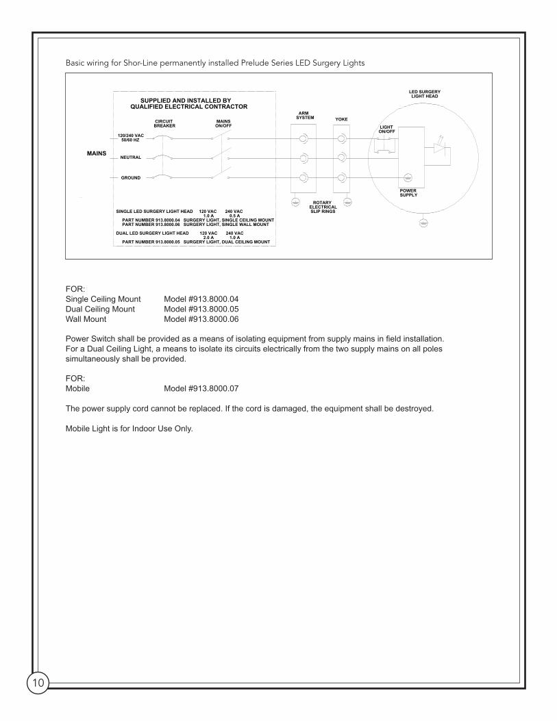
SINGLE LED SURGERY LIGHT HEAD 120 VAC 240 VAC 1.0 A 0.5 A PART NUMBER 913.8000.04 SURGERY LIGHT, SINGLE CEILING MOUNT PART NUMBER 913.8000.06 SURGERY LIGHT, SINGLE WALL MOUNT
DUAL LED SURGERY LIGHT HEAD 120 VAC 240 VAC 2.0 A 1.0 A PART NUMBER 913.8000.05 SURGERY LIGHT, DUAL CEILING MOUNT
BASIC WIRING FOR SHORLINE PERMANENTLY INSTALLED PRELUDE SERIES LED SURGERY LIGHTS
LIGHTON/OFF
Basic wiring for Shor-Line permanently installed Prelude Series LED Surgery Lights
FOR:Single Ceiling Mount Model #913.8000.04Dual Ceiling Mount Model #913.8000.05Wall Mount Model #913.8000.06
Power Switch shall be provided as a means of isolating equipment from supply mains in field installation.For a Dual Ceiling Light, a means to isolate its circuits electrically from the two supply mains on all poles simultaneously shall be provided.
FOR:Mobile Model #913.8000.07
The power supply cord cannot be replaced. If the cord is damaged, the equipment shall be destroyed.
Mobile Light is for Indoor Use Only.

Shor-Line | 800.444.1579 | shor-line.com 11
Section 3: Single Ceiling Mount and Installation (Option 1)
Single Ceiling Mount
Pre-Installation Check
IMPORTANT: For the safety of installers and equipment users, Shor-Line requires all installation and repairs be performed by a licensed electrician. Failure to comply will result in a void of all Shor-Line warranties.
Single Ceiling Mount Light Systems are heavy. Precautions must be taken. Utilize two or more people when installing.ATTENTION Les systèmes de lampe de plafond sont lourds. Des précautions doivent être prises. L'installation requiert au moins deux personnes.
Improper installation of Single Ceiling Mount Light Systems can cause serious injury and/or property damage. Installation requirements may vary depending upon the building construction encountered. The mounting hardware supplied is designed for standard wood studs. It is the installer's responsibility to provide any alternative mounting hardware for other types of construction.ATTENTION Une mauvaise installation du système de lampe de plafond peut provoquer des blessures graves et/ou des dommages matériels. Le mode d'ancrage peut varier en fonction du type de construction du bâtiment. Les pièces de montage fournies sont conçues pour être ancrées à des pièces de charpente en bois ordinaires. Si le produit est ancré dans un autre type de construction, il incombe à l'installateur de fournir toutes les pièces de montage adaptées.
• Each mounting joist or support must hold a minimum of 100 pounds.• The mounting joists or support are on 16" centers so it can accommodate the mounting plate with dimensions of 18" L x 9.25" W.• Power supply lines must be two wire with ground, single phase.120VAC.50/60 Hz, capable of supplying 1.0 amps for each light assembly-two wire with ground, single phase 240 VAC - 50/60 Hz, capable of supplying .5 amps for each light assembly.• Maintain proper grounding. Ground wire connections within the wall mount must be fastened at all times.• Light Mount Column supplied, make sure it is the proper length to install and operate the Light System without interference or overreach.
Tools Required• Electric Drill• 3/16" Drill Bit• Phillips and Flathead Screwdrivers• Tape Measure• Level• Internal Snap Ring Pliers• Standard Electrician Tools
Equipment/PartsThe shipping carton contains a Prelude Single Ceiling Mount Assembly, (with washers and retaining ring inside the top of the Protective Cover) attached to a sturdy mounting plate with a Decorative Cover. A Single Ceiling Mount Arm Assembly with Pivot Cover, a Prelude LED Surgery Light Head Assembly and a plastic bag containing (6) wood screws and an allen wrench.

12
Turn off electricity to the circuit.ATTENTION Couper l'alimentation en électricité au panneau.
Step 1Slide the Column Cover down the shaft and remove. Retrieve the allen wrench that is attached to the column base. See Fig. 1.
NOTE: Do not discard the allen wrench as it will be used to secure the cover after the mounting is complete.
Step 2Unscrew the two phillips head screws securing the Decorative Cover to the mounting plate and remove.
Step 3Prior to Installation, locate the ceiling joists and location for the ceiling mounting plate. See Fig. 2.
The mounting plate has six mounting holes provided for ceiling joist on 16" centers. If necessary, cut a hole in the sheet rock 9.5" x 14.5".
Lift the ceiling mount assembly to the ceiling and using the holes as templates, pre-drill six holes into the ceiling joists (use 3/16" drill bit).
NOTE: The ceiling mount assembly is heavy and must be held up for several minutes. Two or more installers are required for this step.
Step 4Secure the ceiling mount assembly to the ceiling joists using a 2-1/2" Wood Screw at each of the six holes in the mounting plate.
NOTE: If the mounting plate is not properly secured to the ceiling joists, it may result in a mounting system failure causing the light to fall from the ceiling. ALL SIX SCREWS must be used.
MOUNTING PLATE
COLUMN SHAFT
MOUNTING SCREWS
COLUMN COVER
MAIN POWER CIRCUIT WIRING
PROTECTIVE COVER
DECORATIVECOVER
18.0 REF
9.3 REF
16.00 CENTERS
14.000
MOUNTING PLATE
D
C
B
A
123
8 7 6 5 4 3 2 1
E
F
E
F

Shor-Line | 800.444.1579 | shor-line.com 13
Step 5• After securing the ceiling mount assembly connect the main power circuit wiring.
• Route and secure main power through the access hole located on the mounting plate. See Fig. 3.
• Strip a 1/4" of insulation from the end of each of the Main Power Circuit Wires.
• Attach the main power circuit wiring to the terminal block located on ceiling mount column, based on the designated locations for ground, neutral and load.
Step 6Re-attach the Decorative Cover using the two screws removed in Step 2. See Fig. 4.
Step 7Using the allen wrench retrieved in Step 1, replace the column cover and tighten each of the (3) screws to secure the cover to the column shaft.
The light system should NOT be energized
at this time.ATTENTION Le système d'éclairage doit rester hors tension à ce moment.
MAIN POWERACCESS HOLE
TERMINAL BLOCK
TERMINAL BLOCK
NEUTRAL LOAD
GROUND
COLUMN COVER SCREWS
DECORATIVE COVER SCREWS
14
Installation of Single Ceiling Mount Arm Assembly
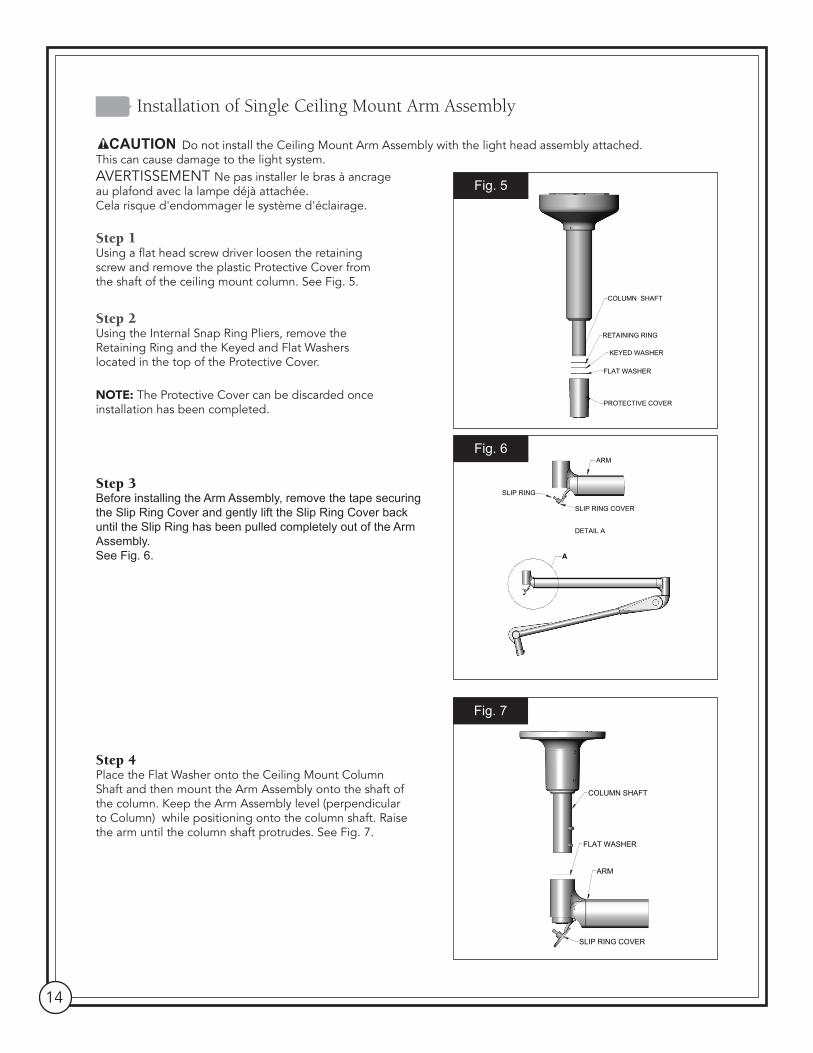
Do not install the Ceiling Mount Arm Assembly with the light head assembly attached. This can cause damage to the light system.AVERTISSEMENT Ne pas installer le bras à ancrage au plafond avec la lampe déjà attachée. Cela risque d'endommager le système d'éclairage.
Step 1Using a flat head screw driver loosen the retaining screw and remove the plastic Protective Cover from the shaft of the ceiling mount column. See Fig. 5.
Step 2 Using the Internal Snap Ring Pliers, remove the Retaining Ring and the Keyed and Flat Washers located in the top of the Protective Cover.
NOTE: The Protective Cover can be discarded once installation has been completed.
Step 3Before installing the Arm Assembly, remove the tape securing the Slip Ring Cover and gently lift the Slip Ring Cover back until the Slip Ring has been pulled completely out of the Arm Assembly. See Fig. 6.
Step 4Place the Flat Washer onto the Ceiling Mount Column Shaft and then mount the Arm Assembly onto the shaft of the column. Keep the Arm Assembly level (perpendicular to Column) while positioning onto the column shaft. Raise the arm until the column shaft protrudes. See Fig. 7.
COLUMN SHAFT
FLAT WASHER
ARM
SLIP RING COVER
A
DETAIL A
SLIP RING
ARM
SLIP RING COVER
PROTECTIVE COVER
RETAINING RING
FLAT WASHER
KEYED WASHER
COLUMN SHAFT
D
C
B
A
D
123456
8 7 6 5 4 3 2 1
E
F
E
F

Shor-Line | 800.444.1579 | shor-line.com 15
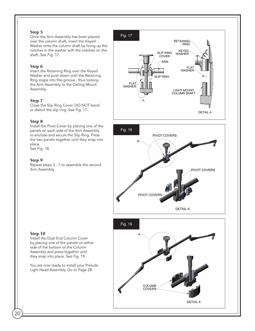
Step 5Once the Arm Assembly has been placed over the column shaft, insert the Keyed Washer onto the column shaft by lining up the notches in the washer with the notches on the shaft.See Fig. 8.
Step 6 Insert Retaining Ring over the Keyed Washer and push upwards until the Retaining Ring snaps into the groove - thus locking the Arm Assembly to the Ceiling Mount Assembly.
The Ceiling Mount Arm Assembly is heavy and must be held up for several minutes. Assembly requires two or more people.AVERTISSEMENT L'ensemble du bras à ancrage au plafond est lourd et il doit être tenu pendant plusieurs minutes. Son assemblage doit être effectué par au moins deux personnes.
Step 7Close the Slip Ring. DO NOT bend or distort the Slip Ring. See Fig. 9.
Step 8Install the Pivot Cover by placing one of the panels on each side of the Arm Assembly to enclose and secure the Slip Ring. Press the two panels together until they snap into place. See Fig. 10.
You are now ready to install your Prelude Light Head Assembly. Go to page 28.
A
ARMSLIP RING
SLIP RING COVER
DETAIL A
KEYEDWASHER
RETAINING RING
FLATWASHER
COLUMN SHAFT
SLIP RING COVER
A
DETAIL A
16
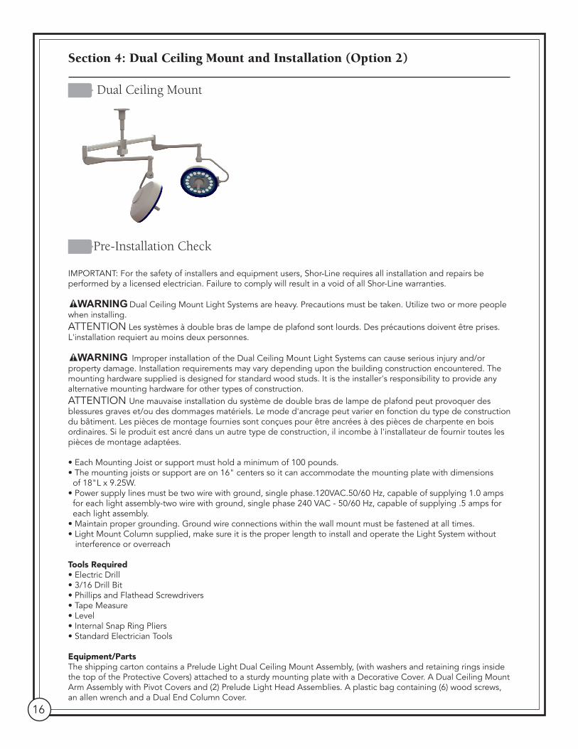
Section 4: Dual Ceiling Mount and Installation (Option 2)
Dual Ceiling Mount
Pre-Installation Check
IMPORTANT: For the safety of installers and equipment users, Shor-Line requires all installation and repairs be performed by a licensed electrician. Failure to comply will result in a void of all Shor-Line warranties.
Dual Ceiling Mount Light Systems are heavy. Precautions must be taken. Utilize two or more people when installing.ATTENTION Les systèmes à double bras de lampe de plafond sont lourds. Des précautions doivent être prises. L'installation requiert au moins deux personnes.
Improper installation of the Dual Ceiling Mount Light Systems can cause serious injury and/or property damage. Installation requirements may vary depending upon the building construction encountered. The mounting hardware supplied is designed for standard wood studs. It is the installer's responsibility to provide any alternative mounting hardware for other types of construction.ATTENTION Une mauvaise installation du système de double bras de lampe de plafond peut provoquer des blessures graves et/ou des dommages matériels. Le mode d'ancrage peut varier en fonction du type de construction du bâtiment. Les pièces de montage fournies sont conçues pour être ancrées à des pièces de charpente en bois ordinaires. Si le produit est ancré dans un autre type de construction, il incombe à l'installateur de fournir toutes les pièces de montage adaptées.
• Each Mounting Joist or support must hold a minimum of 100 pounds.• The mounting joists or support are on 16" centers so it can accommodate the mounting plate with dimensions of 18"L x 9.25W.• Power supply lines must be two wire with ground, single phase.120VAC.50/60 Hz, capable of supplying 1.0 amps for each light assembly-two wire with ground, single phase 240 VAC - 50/60 Hz, capable of supplying .5 amps for each light assembly.• Maintain proper grounding. Ground wire connections within the wall mount must be fastened at all times.• Light Mount Column supplied, make sure it is the proper length to install and operate the Light System without interference or overreach
Tools Required• Electric Drill• 3/16 Drill Bit• Phillips and Flathead Screwdrivers• Tape Measure• Level• Internal Snap Ring Pliers• Standard Electrician Tools
Equipment/PartsThe shipping carton contains a Prelude Light Dual Ceiling Mount Assembly, (with washers and retaining rings inside the top of the Protective Covers) attached to a sturdy mounting plate with a Decorative Cover. A Dual Ceiling Mount Arm Assembly with Pivot Covers and (2) Prelude Light Head Assemblies. A plastic bag containing (6) wood screws, an allen wrench and a Dual End Column Cover.

Shor-Line | 800.444.1579 | shor-line.com 17
Turn off electricity to the circuit.ATTENTION Couper l'alimentation en électricité au panneau.
Step 1 Slide the Column Cover down the column shaft. Retrieve the allen wrench that is attached to the column base. See Fig. 11.
NOTE: Do not discard the allen wrench as it will be used to secure the cover after the mounting is complete.
Step 2Unscrew the two phillips head screws securing the Decorative Cover and lower it down to reveal the mounting plate.
Step 3Prior to Installation, locate the ceiling joists and location for the ceiling mounting plate.
The mounting plate has six mounting holes provided for ceiling joist on 16" centers. If necessary, cut a hole in the sheet rock 9.5" x 14.5". See Fig. 12.
Lift the Column Mount Assembly to the ceiling and using the holes as templates, pre-drill six holes into the ceiling joists (use 3/16 drill bit).
NOTE: The column is heavy and must be held up for several minutes. Two or more installers are required for this step.
Step 4Secure the Ceiling Mount Assembly to the ceiling joists using a 2-1/2" Wood Screw at each of the six holes in the mounting plate.
NOTE: If the mounting plate is not properly secured to the ceiling joists, it may result in a mounting system failure causing the light to fall from the ceiling. ALL SIX SCREWS must be used.
18.0 REF
9.3 REF
16.00 CENTERS
14.000
MOUNTING PLATE
D
C
B
A
123
8 7 6 5 4 3 2 1
E
F
E
F
Fig. 12
MOUNTING SCREWS
MOUNTING PLATE
MAIN POWERCIRCUIT WIRING
COLUMN COVER
PROTECTIVE COVERS
DUAL ENDCOLUMN COVER
DECORATIVE COVER
COLUMN SHAFT
D
C
B
A
D
123456
8 7 6 5 4 3 2 1
E
F
E
F
Fig. 11
18
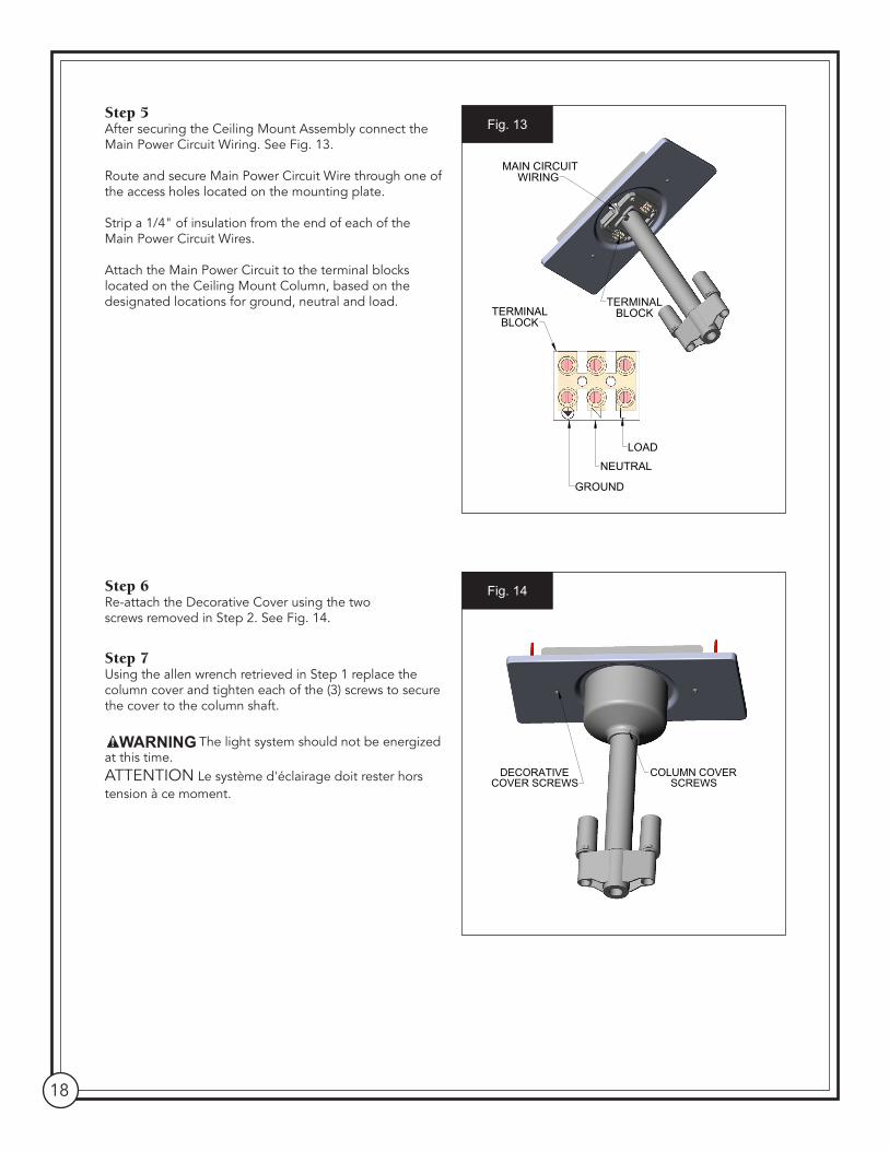
Step 5 After securing the Ceiling Mount Assembly connect the Main Power Circuit Wiring. See Fig. 13.
Route and secure Main Power Circuit Wire through one of the access holes located on the mounting plate.
Strip a 1/4" of insulation from the end of each of the Main Power Circuit Wires.
Attach the Main Power Circuit to the terminal blocks located on the Ceiling Mount Column, based on the designated locations for ground, neutral and load.
Step 6Re-attach the Decorative Cover using the two screws removed in Step 2. See Fig. 14.
Step 7Using the allen wrench retrieved in Step 1 replace the column cover and tighten each of the (3) screws to secure the cover to the column shaft.
The light system should not be energized at this time.ATTENTION Le système d'éclairage doit rester hors tension à ce moment.
TERMINAL BLOCK
GROUND
NEUTRAL
LOAD
TERMINAL BLOCK
MAIN CIRCUIT WIRING
Fig. 13
DECORATIVECOVER SCREWS
COLUMN COVER SCREWS
D
C
B
A
D
123456
8 7 6 5 4 3 2 1
E
F
E
F
Fig. 14
Shor-Line | 800.444.1579 | shor-line.com 19
Installation of Dual Ceiling Mount Arm Assembly
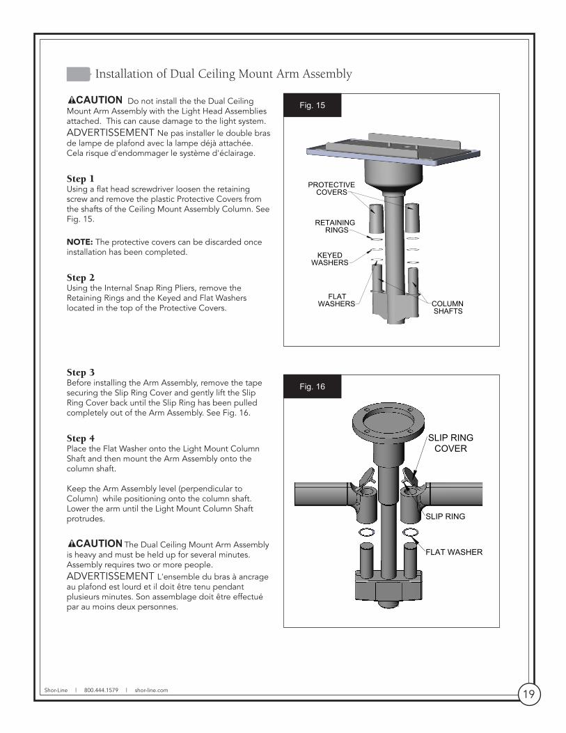
Do not install the the Dual Ceiling Mount Arm Assembly with the Light Head Assemblies attached. This can cause damage to the light system.ADVERTISSEMENT Ne pas installer le double bras de lampe de plafond avec la lampe déjà attachée. Cela risque d'endommager le système d'éclairage.
Step 1Using a flat head screwdriver loosen the retaining screw and remove the plastic Protective Covers from the shafts of the Ceiling Mount Assembly Column. See Fig. 15.
NOTE: The protective covers can be discarded once installation has been completed.
Step 2 Using the Internal Snap Ring Pliers, remove the Retaining Rings and the Keyed and Flat Washers located in the top of the Protective Covers.
Step 3Before installing the Arm Assembly, remove the tape securing the Slip Ring Cover and gently lift the Slip Ring Cover back until the Slip Ring has been pulled completely out of the Arm Assembly. See Fig. 16.
Step 4Place the Flat Washer onto the Light Mount Column Shaft and then mount the Arm Assembly onto the column shaft.
Keep the Arm Assembly level (perpendicular to Column) while positioning onto the column shaft. Lower the arm until the Light Mount Column Shaft protrudes.
The Dual Ceiling Mount Arm Assembly is heavy and must be held up for several minutes. Assembly requires two or more people.ADVERTISSEMENT L'ensemble du bras à ancrage au plafond est lourd et il doit être tenu pendant plusieurs minutes. Son assemblage doit être effectué par au moins deux personnes.
PROTECTIVE COVERS
RETAINING RINGS
KEYED WASHERS
FLAT WASHERS COLUMN
SHAFTS
D
C
B
A
D
12345
8 7 6 5 4 3 2 1
E
F
E
F
Fig. 15
SLIP RING COVER
SLIP RING
FLAT WASHER
Fig. 16
20
Step 5Once the Arm Assembly has been placed over the column shaft, insert the Keyed Washer onto the column shaft by lining up the notches in the washer with the notches on the shaft. See Fig. 17.
Step 6 Insert the Retaining Ring over the Keyed Washer and push down until the Retaining Ring snaps into the groove - thus locking the Arm Assembly to the Ceiling Mount Assembly.
Step 7Close the Slip Ring Cover. DO NOT bend or distort the slip ring. See Fig. 17.
Step 8Install the Pivot Cover by placing one of the panels on each side of the Arm Assembly to enclose and secure the Slip Ring. Press the two panels together until they snap into place. See Fig. 18.
Step 9 Repeat steps 3 - 7 to assemble the second Arm Assembly.
Step 10Install the Dual End Column Cover by placing one of the panels on either side of the bottom of the Column Assembly and press together until they snap into place. See Fig. 19.
You are now ready to install your Prelude Light Head Assembly. Go to Page 28.
A
ARM
FLATWASHER
SLIP RING COVER
SLIP RING
DETAIL A
FLATWASHER
KEYEDWASHER
RETAININGRING
LIGHT MOUNTCOLUMN SHAFT
Fig. 17
A
PIVOT COVERS
DETAIL A
PIVOT COVERS
PIVOT COVERS
Fig. 18
A
DETAIL A
COLUMN COVERS
Fig. 19

Shor-Line | 800.444.1579 | shor-line.com 21
Section 5: Wall Mount Light System and Installation (Option 3)
Wall Mount Light
Pre-Installation Check
IMPORTANT: For the safety of installers and equipment users, Shor-Line requires all installation and repairs be performed by a licensed electrician. Failure to comply will result in a void of all Shor-Line warranties.
Improper installation of the Wall Mount Light System can cause serious injury and/or property damage. Installation requirements may vary dependent upon the building construction encountered. The mounting hardware supplied is designed for standard wood studs. It is the installers' responsibility to provide any alternative mounting hardware for other types of construction.ATTENTION Une mauvaise installation du système de lampe de plafond peut provoquer des blessures graves et/ou des dommages matériels. Le mode d'ancrage peut varier en fonction du type de construction du bâtiment. Les pièces de montage fournies sont conçues pour être ancrées à des pièces de charpente en bois ordinaires. Si le produit est ancré dans un autre type de construction, il incombe à l'installateur de fournir toutes les pièces de montage adaptées.
• Each Mounting Joist or support must hold a minimum of 100 pounds.• Power supply lines must be two wire with ground, single phase.120VAC.50/60 Hz, capable of supplying 1.0 amps for each light assembly-two wire with ground, single phase 240 VAC - 50/60 Hz, capable of supplying .5 amps for each light assembly.• Maintain proper grounding. Ground wire connections within the wall mount must be fastened at all times.
TOOLS REQUIRED• Electric Drill• 3/16" Drill Bit• Phillips and Flathead Screwdrivers• Tape Measure• Level• Standard Electrician Tools• 5/16" Hex Wrench
Equipment/PartsThe shipping carton contains a Prelude Light Wall Mount Assembly, a Wall Mount Arm Assembly, a Prelude Light Head Assembly and mounting hardware which consist of two wood screws (#14x21/2" long), two flat washers, one post washer, one retaining ring, terminal block, (1) #8-32x .500 Flat Head Screw, (1) #8-32 Hex Nut and (1) #8 Flat Washer.

22
Installation of Wall Mount Assembly
Turn off electricity to the circuit.ATTENTION Couper l'alimentation en électricité au panneau.
Step 1Remove the two screws used to secure the upper cover. See Fig. 20.
Step 2Remove the two screws used to secure the bottom cover.
Step 3 Determine where to attach the mounting plate. See Fig. 21.Install to a backing with sufficient support (a wall stud or backing plate). Recommended height is 84.5 inches from floor to top of post.
Step 4 Attach the mounting plate at the determined location using the two 2½" long wood screws and two flat washers provided.
Step 5 Remove Terminal Block Cover.
WALL MOUNT POST
TOP COVER
BOTTOM COVER
COVER SCREWS
Fig. 20
84.5 TO FLOORFROM TOP OF
WALL MOUNT POST)
MOUNTING HOLES
WALL STUD
TERMINAL BLOCK COVER
Fig. 21

Shor-Line | 800.444.1579 | shor-line.com 23
Step 6Route and secure Main Power Circuit Wire through one of the access holes located on the mounting plate. See Fig 22.
Step 7 Using a 5/16 hex wrench, loosen the hex nut securing the wire clamp attached to the mounting plate.
Step 8 Route main wire through clamp and secure using a 5/16 hex wrench to tighten the hex nut.
Step 9Strip ¼" of insulation from the end of each of the Main Power Circuit wires. See Fig. 23.
Step 10Attach the Main Power Circuit wiring to the terminal block located on the mounting plate. See Fig. 23.
Step 11Ensure the post mount washer is in place on the shaft of the wall mount post. See Fig. 24.
Step 12Place the Upper Cover over post mount washer and secure using the two screws removed in Step 1. See Fig. 24.
The light system should not be energized at this time.ATTENTION Le système d'éclairage doit rester hors tension à ce moment.
WALL STUD
MAIN POWER CIRCUIT WIRE
MAIN POWER CIRCUIT WIRES
TERMINAL BLOCK
Fig. 23
WALL STUD
MAIN POWER CIRCUIT WIRE
HEX NUT
WIRE CLAMP
MOUNTING HARDWARE
ACCESS HOLES FOR MAIN POWER
Fig. 22
WALL STUD
UPPER COVER
POST MOUNT WASHER
UPPER COVER SCREWSFig. 24

24
Installation of Wall Mount Arm Assembly
Do not install the Wall Mount Arm Assembly with the Light Head Assembly attached. This can cause damage to the light system.ADVERTISSEMENT Ne pas installer le bras d'ancrage au mur avec la lampe déjà attachée. Cela risque d'endommager le système d'éclairage.
Step 1Before installing the Arm Assembly, remove the tape securing the Slip Ring Cover and gently lift the Slip Ring back until it has been pulled completely out of the Arm Assembly. See Fig. 25.
Step 2Place the Arm Assembly on the post protruding through the hole in the Upper Cover. See Fig. 26.
Step 3Pull Arm Assembly wires out through the Slip Ring Cover opening.
Step 4Insert retaining ring into the groove located on the top of the mounting post.
Step 5Once retaining ring is in place, feed Arm Assembly wires down through the hole in the Mounting Shaft.
Step 6Close the Slip Ring Cover. DO NOT bend or distort Slip Ring.
Step 7Strip a ¼" of insulation from the end of each of the Arm Assembly wires. See Fig. 27.
ARM ASEMBLY
SLIP RING SLIP RING COVER
Fig. 25
SLIP RING COVER
ARM ASSEMBLY WIRES
SHAFT MOUNTING HOLE
RETAINING RING GROVE
RETAINING RING
Fig. 26
Shor-Line | 800.444.1579 | shor-line.com 25
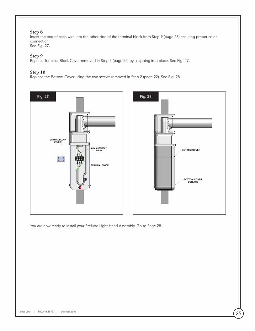
Step 8Insert the end of each wire into the other side of the terminal block from Step 9 (page 23) ensuring proper color connection. See Fig. 27.
Step 9Replace Terminal Block Cover removed in Step 5 (page 22) by snapping into place. See Fig. 27.
Step 10Replace the Bottom Cover using the two screws removed in Step 2 (page 22). See Fig. 28.
You are now ready to install your Prelude Light Head Assembly. Go to Page 28.
ARM ASSEMBLY WIRES
TERMINAL BLOCK
TERMINAL BLOCK COVER
Fig. 27
BOTTOM COVER
BOTTOM COVER SCREWS
Fig. 28
26
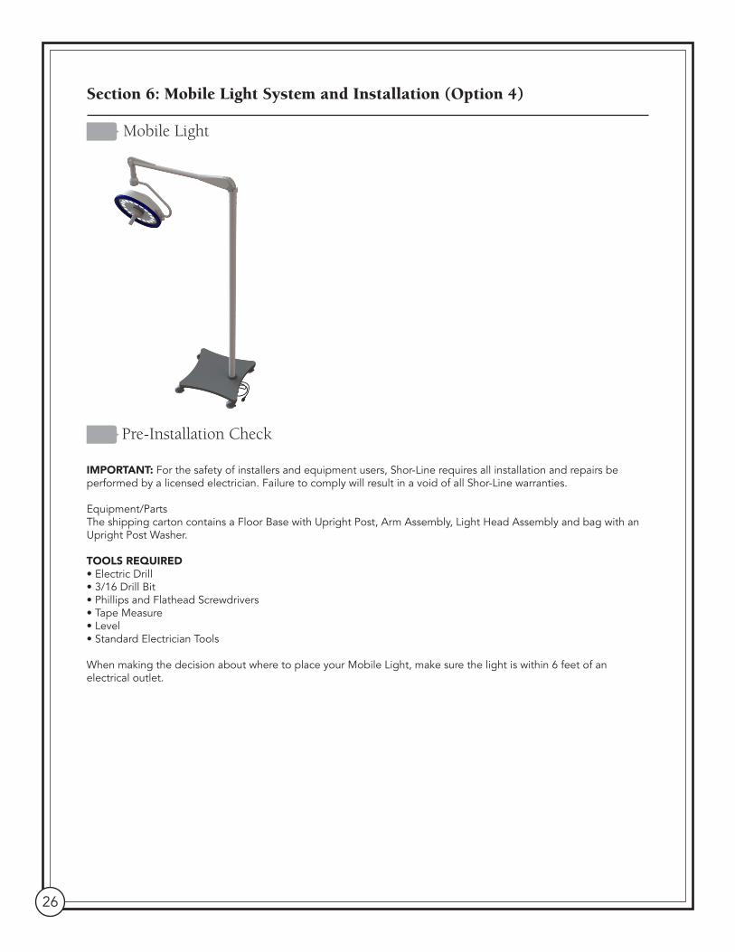
Section 6: Mobile Light System and Installation (Option 4)
Mobile Light
Pre-Installation Check
IMPORTANT: For the safety of installers and equipment users, Shor-Line requires all installation and repairs be performed by a licensed electrician. Failure to comply will result in a void of all Shor-Line warranties.
Equipment/PartsThe shipping carton contains a Floor Base with Upright Post, Arm Assembly, Light Head Assembly and bag with an Upright Post Washer.
TOOLS REQUIRED• Electric Drill• 3/16 Drill Bit• Phillips and Flathead Screwdrivers• Tape Measure• Level• Standard Electrician Tools
When making the decision about where to place your Mobile Light, make sure the light is within 6 feet of an electrical outlet.

Shor-Line | 800.444.1579 | shor-line.com 27
Upright Post Assembly
Step 1Floor Base with Upright Post is pre-assembled in the factory. Upright Post and Arm Assembly are pre-wired. See Fig. 29.
Do not remove the four screws at the top of the Upright Post that secures the internal wiring mechanism. Removing these screws will cause the mechanism to slip down the shaft of the post which will result in a loss of electrical connectivity.ADVERTISSEMENT Ne pas retirer les quatre vis à la partie supérieure du poteau vertical qui renferme le mécanisme de câblage interne. Sans ces vis, le mécanisme glissera vers le bas le long du poteau, ce qui provoquera une perte de continuité dans le circuit électrique.
Step 2 Place Post Washer over the Arm Assembly Post and position Arm Assembly into the top of the Upright Post. Keep Arm Assembly level (perpendicular to post) while lowering Arm Assembly into the shaft of the Upright Post. See Fig. 30.
Do not install the Arm Assembly with the Light Head Assembly attached. This can cause damage to the light system.ATTENTION Ne pas retirer les quatre vis à la partie supérieure du poteau vertical qui renferme le mécanisme de câblage interne. Sans ces vis, le mécanisme glissera vers le bas le long du poteau, ce qui provoquera une perte de continuité dans le circuit électrique.
NOTE: The Arm Stop, located at the top of the Upright Post, prevents the Arm Assembly from moving more than 160° and maintains the stability of the Mobile Base.
Step 3See LIGHT HEAD TO ARM ASSEMBLY, page 28.
NOTE: If Arm doesn't hold (drops) the light head, or if the tension is too strong, see ARM ASSEMBLY ADJUSTMENT, page 30.
Step 4Connect power cord to an electrical outlet and verify operation. See FUNCTIONALITY, page 31.
MOBILE POST
MOBILE BASE
POWER CORD
CASTERS WITHOUT BRAKE
CASTERS WITHBRAKE
PHILLIPS SS TRUSS HEAD SCREWS
B
F
Fig. 29
POST WASHER
MOBILE POST
ARM ASSEMBLY POST
E
F
Fig. 30

28
Section 7: Light Head Assembly
Light Head to Arm Assembly
Attaching the Prelude Light Head Assembly to the Arm Assembly is the same for all mounting options. Both the Light Head Assembly and Arm Assembly have been pre-wired in our factory so parts merely need to be fitted and connected for illumination.
IMPORTANT: For the safety of the installers and equipment users, Shor-Line requires all installation and repairs be performed by a licensed electrician. Failure to comply will result in a void of all Shor-Line warranties.
IMPORTANT: The spring Lock restricts movement of the Arm Assembly and must not be removed until the Light Head is completely attached.
Tools Required• Flathead Screwdriver • Needle Nose Pliers
Step 1Remove the Screw on the Locking Sleeve. See Fig. 31.
Step 2Using a flathead screwdriver, push back the plastic locking tab inside the locking sleeve to release the sleeve.
Step 3Push the sleeve upwards on the Arm Assembly.
NOTE: The sleeve cannot move unless the tab is completely unlocked.
Step 4Using needle nose pliers remove the copper metal clip that is now exposed on the arm receptacle. See Fig 32.
Step 5Remove the plastic cap from the end of the Light Head Slip Ring attachment.
Step 6Push the Light Head Slip Ring attachment into the arm receptacle.
SCREWDRIVER(PUSH TAB OUT)
LOCKING TAB
METAL CLIP
LOCKING SLEEVE
PUSHSLEEVEUP
Fig. 31
ARMRECEPTACLE
METAL CLIP
ARM ASSEMBLY
SLOT
SLIP RINGGROOVE
HEAD SLIP RING ATTACHMENT
LIGHT HEAD
PLASTIC CAP
Fig. 32

Shor-Line | 800.444.1579 | shor-line.com 29
Step 7Align the groove in the Light Head Slip Ring with the slot in the Arm Receptacle.
Step 8Once the units are lined up reinsert the copper metal clip into the Arm Receptacle slot. See Fig. 33.
Step 9Push the locking sleeve downward until the plastic tab locks into place (clicks).
Step 10Replace the Locking Sleeve screw removed in Step 1. See Fig. 34.
Step 11Remove the screw from the spring lock to engage the spring.
NOTE: If the Arm Assembly does not hold the Light Head (drops) or if the tension is too strong, go to Arm Assembly Adjustment on Page 30.
You can now energize the mains.
You are now ready to test your Prelude Light system for proper fit and function. See page 31.
LOCKINGSLEEVE
METAL CLIP
ARM ASSEMBLY
ARMRECEPTACLESLOT
LIGHT HEAD
PUSHSLEEVEDOWN
Fig. 33
SCREW
ARM ASSEMBLY
LIGHT HEAD
DISENGAGE SPRINGLOCK
Fig. 34

30
Section 8: Arm Assembly and Adjustments
The Arm Assembly has been pre-adjusted at our factory. If the Arm Assembly does not hold the Light Head Assembly (drops) or if the tension is too strong then adjustments are necessary.
IMPORTANT: Adjustments can only be made to the Arm Assembly when a Light Head Assembly is attached and the screw has been released from the Spring Lock (See Step 11, LIGHT HEAD TO ARM ASSEMBLY, page 29).
Step 1Lift the cover on the top of the Arm Assembly. See Fig. 35.
Step 2Mounted on the inside of the Arm Assembly Cover is a 4 mm x 110 mm Dowel Pin used to adjust the tension.
Step 3Looking down into the Arm Assembly opening, there are two slots that allow you access to the Adjustment Wheel.
The Adjustment Wheel contains multiple holes the size of the Dowel Pin and based on the direction turned will tighten or loosen the tension on the spring located in the Arm Assembly.
To further assist you the "+/-" symbols have been embossed in the plastic arm.
• If the Arm Assembly drops too easily turn the Dowel Pin towards the " + " to increase the tension.
• If the Arm Assembly rises too easily turn the Dowel Pin towards the " - " to decrease the tension.
As you turn the wheel, test the tension of the Arm Assembly. DO NOT OVER TIGHTEN.
Step 4When adjustments are complete return the Dowel Pin to its original position and close the cover.
ADJUSTMENT SLOTS
ARM ASSEMBLY COVER
ADJUSTMENT WRENCH
Fig. 35

Shor-Line | 800.444.1579 | shor-line.com 31
Section 9: Functionality
Shor-Line Prelude LED Light Functions
Your Prelude LED Surgery Light comes equipped with the following features:
• 18 White Light LEDs with individual parabolic reflectors.• 6" diameter field provides shadow free beam at 4500K.• Independent On-Off switch.• Adjustable dimming from 40k LUX to 100k LUX by pressing the up or down arrows.• Autoclaveable handle - push the quick release button and pull the handle to remove.
LED lights generate heat. Please use constant caution and best practice when placing LED light next to patient's wounds.ATTENTION Les lampes à DEL dégagent de la chaleur. Veuillez faire preuve de prudence en tout temps et respecter les meilleures pratiques lorsque la lampe à DEL est placée à proximité des plaies du patient.

32
Section 10: LED Surgery Light Safety, Maintenance and Cleaning
Safety Instructions
Only facility authorized maintenance personnel should troubleshoot or repair the unit. Troubleshooting or repair by unauthorized personnel could result in personal injury and/or property damage.
After repair of the unit, ensure the unit is in proper working order. Failure to do so could result in personal injury and/or property damage.
Do not pinch any wires during installation. Pinched wires can cause an electrical shock hazard, resulting in personal injury and/or property damage.
LED Light Maintenance
The LED life (L70) is rated such that the LED will deliver, on average, 70% lumen maintenance at 50,000 hours of operation (approximately 17 years at 8 hours per day).
If one or more LED(s) are off and/or generate noticeably dim light output, contact our Technical Services department. The LED(s) are not readily replaceable by end users and should only be serviced by Shor-Line or facility authorized maintenance personnel.
Cleaning
Units operate at high temperatures. Allow the unit to cool at least 30 minutes before performing any maintenance. Failure to do so could result in personal injury.
Do not expose the unit to excessive moisture or spills. Failure to do so could result in personal injury and/or property damage.
Do not use harsh cleaners, solvents or detergents. Failure to do so could result in equipment damage.
Clean the lens using glass/plastic cleaner or mild soap and water mix. It is very important to use a clean, soft cloth to avoid any scratching of the front lens. Never spray the cleaning fluid directly onto the Light Head or Arm.
Disposal Of Waste
This product must not be disposed of with your other waste. Instead, it is your responsibility to dispose of your waste equipment by handing it over to a designated collection point for the recycling of waste electrical and electronic equipment, or by returning it to Shor-Line for reprocessing.
The separate collection and recycling of your waste equipment at the time of disposal will help to conserve natural resources and ensure that it is recycled in a manner that protects human health and the environment.
For more information about where you can drop off your waste equipment for recycling, please contact your local city office or your waste disposal service provider.

Shor-Line | 800.444.1579 | shor-line.com 33
Protecting Against Disease & Infection
IMPORTANT: Shor-Line shares your commitment to health and safety. This information is intended help protect your animals, as well as, safeguard your investment.
• Bleaches can be harmful to animals. Bleaches can react with acids and release chlorine gas that is highly toxic. • Because of its strong corrosive and toxic properties, bleach is diluted with water. The solution’s potency (shelf-life) quickly degrades as the active chlorine dissipates with water. Animal care professionals, therefore, cannot know with certainty how effective the bleach solution is over time without implementing a formal monitoring system.
• If chemical deodorizers, disinfectants, or sanitizers are used, protect your animals from respiratory problems and infections by using clean water to wash residue from all surfaces and dry thoroughly.
• Clorox® Company warns: “We cannot recommend Clorox® to clean metal surfaces, including stainless steel. Prolonged or repeated exposure of metal to strong solutions of our product eventually can cause discoloration or corrosion. To reduce the possibility of metal discoloration, we suggest that exposure time to Clorox® be less than five minutes and that surfaces be rinsed well after application of the solution.”
34
Section 11: Services, Terms & Conditions and Warranty
Terms & ConditionsORDER & ACCEPTANCE By submitting an order for the products described herein, Buyer shall have agreed to purchase the products subject to all Seller’s terms including these TERMS and CONDITIONS. Buyer’s order is subject to and effective only upon acceptance and approval at Seller’s offices in Kansas City, Kansas as evidenced by Seller’s issuance of an Order Acknowledgement or Invoice. Processing of an order shall not commence until receipt of any applicable deposit and all required paperwork and customer sign-offs. The resulting contract shall be deemed made in Kansas and shall in all respects be governed and interpreted according to the laws of the State of Kansas. Buyer also consents to the jurisdiction of Kansas courts over any dispute involving this order.
ENTIRE AGREEMENT This order as accepted and approved by Seller constitutes the entire final agreement between the parties. Except as otherwise provided in writing by Seller, the terms set forth herein constitute the sole TERMS AND CONDITIONS for Buyer’s order. Seller’s acceptance of Buyer’s order is expressly conditioned on Buyer’s assent to these TERMS AND CONDITIONS which may not be supplemented, modified, superseded or otherwise altered except as authorized in writing by Seller. Any different, conflicting or additional terms in Buyer’s purchase order or any other document of Buyer are rejected and Seller’s TERMS AND CONDITIONS shall prevail.
TERMS OF PAYMENT Unless otherwise expressly specified by Seller in writing, payment shall be due 30 days from the date of invoice, payable in U.S. Funds. Seller reserves the right to negotiate terms or orders of any unique or special nature and may require full or partial payment in advance in its sole discretion. Acceptance of all orders and the payment terms for such orders are subject to approval by Seller’s Credit Department. Seller may decline to make any shipment or perform any work except upon terms satisfactory to said Department. A charge of 1½% per month (or the highest monthly interest rate that may be imposed under applicable law) will be imposed on overdue accounts. Buyer will be liable for all expenses (including reasonable attorneys’ fees) incurred in collecting any overdue accounts.
PRICES & QUOTES Prices on products specified herein are F.O.B. Seller’s factory unless otherwise specified in writing and are exclusive of any city, state, local or federal tax. Prices are subject to adjustment without notice and Seller reserves the right to correct errors in prices or specifications. Any quotation (whether written or oral) is not an offer to contract or acceptance of an order. Similarly, neither a price list nor a catalog constitutes an offer to sell or contract, but are provided solely for customers’ convenience.
TAXES Any sales, use, property, or other taxes or duties which Seller may be required to pay or collect (under any existing or future law) in connection with the sale, purchase, delivery, storage, processing, consumption or use of the products purchased herewith shall be for the account of Buyer and Buyer shall promptly reimburse Seller therefore.
DELIVERIES Delivery dates are estimates only and time shall not be of the essence unless specifically provided by Seller in writing. Seller will not have any liability for loss or damage resulting from a delay in a scheduled delivery or for non-delivery resulting from labor trouble, part or material shortages, accident, fire, war, strike, natural disaster, carrier delays or any contingency whatsoever (whether of the same class of those enumerated or otherwise) beyond its reasonable control. Buyer assumes all freight, handling and installation costs and the risk of loss or delay in transit. Seller will assist Buyer with transit arrangements, but Seller shall be free of any liability in connection therewith. Title to all materials and products sold by Seller shall pass to Buyer upon delivery to the carrier and Seller’s responsibility ceases at that time. Risk of loss, injury, or destruction of the products shall be borne by the Buyer and any such loss, injury or destruction shall not release Buyer from payment of the purchase price.
INSPECTION Buyer must inspect all materials for shortages, damages, conformity with order and defects before signing any documentation requested by the carrier. Buyer must immediately complete such inspection and shall not accept delivery of goods that are damaged or not in accordance with the bill of lading or packing slip without proper notification to the carrier and Seller. If goods are damaged, defective, shorted or appear not to conform to the order, Buyer shall discontinue their use and immediately notify the carrier and Seller of such condition and afford a reasonable opportunity to inspect the same. Buyer shall make, or provide Seller in writing with all information necessary to make, a claim against such carrier for any shortage, damage, or discrepancy of the shipment within fifteen (15) days after receipt of the goods. Claims or written information thereon not so presented within fifteen (15) days after receipt of the goods will not be allowed. No products will be taken back and credited or replaced unless arrangements for their return have been made in compliance with Seller’s Return Policy stated below. SEE SELLER’S CATALOG FOR INFORMATION ON HOW TO FILE A FREIGHT CLAIM.

Shor-Line | 800.444.1579 | shor-line.com 35
PRODUCT SATISFACTION In the event Buyer is not fully satisfied with the quality or workmanship of a product purchased hereunder, Seller in its sole discretion may arrange either to credit Seller’s account (excluding shipping and handling costs) or replace the product. However, Buyer must notify Seller in writing of its dissatisfaction within fifteen (15) days of receipt of the product from Seller and immediately discontinue its use. Buyer also must return the rejected product to Seller freight paid within thirty (30) days of its receipt in compliance with Seller’s Return Policy stated below. Seller’s obligation is limited to providing the applicable credit or product replacement, which will be processed only after receipt of the retuned product. In addition, this Product Satisfaction policy does not apply to specially designed, discontinued, used, factory second or repaired products.
LIMITED WARRANTY Seller warrants to the initial purchaser only of products manufactured by it that such products are free from defects in materials or labor for varying periods depending on the particular product and subject to the limitations and conditions set forth herein. Seller’s stainless steel products are warranted to be free from such defects for their normal useful life. Seller’s mechanical and electrical products, parts, devices and components (including such parts, devices and components of stainless steel products), and other-non-stainless steel products are warranted to be free from such defects for only one year. Seller disclaims any express or implied warranty for products not manufactured by Seller and the only warranty available therefore to Buyer is that offered by the products’ manufacturers.
The warranty period shall run from the date of delivery to Buyer. If within the applicable warranty period a product proves to be defective as described herein, Seller will repair or replace the product, at Seller’s sole discretion, conditional upon Buyer’s written notice of the defect within fifteen (15) days after its discovery. Upon receipt of Buyer’s notice including substantiation of Buyer’s status as the initial purchaser and details of the defect, Seller shall advise Buyer whether it plans to repair or replace the product. Seller’s obligation is solely limited to repair or replacement of a defective product and in no event shall Seller be liable for transportation from or to Seller’s offices or any other expense which may arise in connection with this Limited Warranty or the aforementioned Product Satisfaction policy.
SELLER MAKES NO OTHER WARRANTY OR GUARANTEE OF ANY KIND WHATSOVER, WHETHER EXPRESS OR IMPLIED, STATUTORY OR OTHERWISE INCLUDING, BUT NOT LIMITED TO IMPLIED WARRANTIES OF FITNESS, AND/OR MERCHANTABILITY. THE ABOVE LIMITED WARRANTY CONSTITUTES SELLER’S ONLY WARRANTY AND NO PERSON OR ENTITY IS AUTHORIZED, ON BEHALF OF THE SELLER, TO MODIFY OR EXPAND UPON THE PROVISION EXPRESSED IN THIS PARAGRAPH NUMBER NINE. THE SELLER’S LIABILITY UNDER THIS LIMITED WARRANTY SHALL BE LIMITED AS PROVIDED FOR ABOVE AND THE FOREGOING SHALL BE THE BUYER’S SOLE REMEDY AND RECOURSE UNDER THIS CONTRACT. There are no warranties which extend beyond the description on the face hereof and goods are sold as is. Seller’s Limited Warranty is only available to the initial purchaser of its products and is effective only upon compliance with the terms set forth herein.
Buyer agrees that the products subject to this Limited Warranty will be properly maintained in the ordinary course of business. Buyer agrees to comply with all instructions and specifications furnished by Seller relating to the installation, care, use and application of products purchased. Buyer agrees that it will not modify, misapply, or misuse such products in any manner which would deviate from Seller’s instructions. Any repairs, alterations or service provided by parties other than Seller, or its authorized representative, may void this Limited Warranty. This Limited Warranty shall not apply to normal wear and tear, improper or insufficient maintenance, routine maintenance, or damage caused by accident, negligence, improper operation or the use of corrosive materials (including without limitation bleach or sodium hypochlorite used on stainless steel surfaces). THE SELLER’S LIMITED WARRANTY MADE IN CONNECTION WITH THIS SALE SHALL NOT BE EFFECTIVE AND SHALL BE VOID UNLESS SUCH GOODS ARE APPLIED AND USED IN ACCORDANCE WITH SELLER’S INSTRUCTIONS.
LIMITATION OF LIABILITY UNDER NO CIRCUMSTANCES SHALL SELLER BE LIABLE TO BUYER OR ANY OTHER PERSON FOR ANY SPECIAL, LIQUIDATED, INCIDENTAL OR CONSEQUENTIAL DAMAGES, INCLUDING, WITHOUT LIMITATION, DAMAGES BASED UPON LOST GOODWILL, LOST SALES OR PROFITS, WORK STOPPAGE, DELAY, PRODUCT FAILURE, IMPAIRMENT OF GOODS OR OTHERWISE AND WHETHER ARISING OUT OF BREACH OF WARRANTY, BREACH OF CONTRACT, NEGLIGENCE OR OTHERWISE, and in any case, Seller’s liability for any and all losses and damages sustained by Buyer and others, rising out of or by reason of this contract, shall not exceed the original purchase price of the products upon which liability is founded.
IN NO EVENT SHALL ANY ACTION BE COMMENCED AGAINST THE SELLER MORE THAN ONE YEAR AFTER THE CAUSE OF ACTION WITH RESPECT TO WHICH THE CLAIM IS MADE HAS ACCRUED. SELLER SHALL NOT BE RESPONSIBLE FOR EXPENSES FOR REPAIRS NOT MADE BY SELLER WITHOUT THE PRIOR WRITTEN CONSENT OF SELLER.

36
RETURN POLICY All products being returned for any reason or delivered for repair service (whether or not pursuant to our Limited Warranty) must receive advance authorization from Seller. Buyer must contact Seller’s Technical Service Department at 1.800.444.1579 to receive a Return Authorization Number. All products returned, except for warranty service or pursuant to the Product Satisfaction policy, are subject to a minimum 15% restocking charge. Buyer will be responsible for all freight charges on returns.
INDEMNITY Buyer agrees to protect, defend, indemnify and hold harmless the Seller from and against any and all direct loss suffered and any liability to third parties due to bodily injury (including death) to any person or animal, or damage to any property as a result of Buyer’s misuse, misapplication or failure to inspect or maintain the Seller’s products, or such loss or liability caused by the act or omission of the Buyer in the performance of any services using said products. Buyer also agrees to indemnify and hold harmless the Seller for any taxes paid as discussed in paragraph five above. This indemnity provision expressly includes attorney’s fees and settlements of claims in a reasonable manner under the circumstances.
UNLAWFUL USE Buyer agrees that no goods covered by this contract shall be used in any manner violative of any laws of the United States, whether state or federal, or local ordinance, and no such goods shall be distributed to any foreign country in any manner prohibited by United States law.
REGULATIONS AND CODES Seller makes no representation or promise, express or implied, that goods delivered hereunder will conform to any state or local laws, regulations, codes, ordinances, or standards, except as particularly and expressly specified and agreed upon for compliance in writing as a part of the contract between Buyer and Seller.
SELLER’S REMEDIES Seller hereby expressly reserves all remedies provided for by the Uniform Commercial Code and such remedies are expressly cumulative in nature and include all of the available remedies for breach and Seller need not make any election of remedy.
MISCELLANEOUS Buyer may not assign its rights or duties relative to this order without Seller’s written consent, but Seller may assign its interest in such order to any affiliate or successor in interest. The waiver of any breach of these TERMS AND CONDITIONS shall not constitute a waiver as to any further breach. Any of these TERMS AND CONDITIONS found to be invalid, illegal or unenforceable, shall be considered inoperative and the remaining TERMS AND CONDITIONS shall be valid and enforceable as though such provisions are not included herein. Contact our Credit Department toll-free for questions: 800.444.1579

Shor-Line | 800.444.1579 | shor-line.com 37
Shor-Line/Schroer Manufacturing Co.511 Osage AvenueKansas City, KS 66105 U.S.A.
800444.1579
toll free local fax
913281.1500
913281.5339
www.shor-line.com