a guide for regulators - united states environmental ... · a guide for regulators . chapter v ....
TRANSCRIPT
Printed on Recycled Paper
Land And EPA 510-B-16-004 Emergency Management October 2016 5401R www.epa.gov/ust
Expedited Site Assessment Tools For Underground Storage Tank Sites
A Guide For Regulators

Chapter V
Direct Push Technologies

October 2016 FINAL V-ii
Disclaimer
The purpose of the revised release of this document is to facilitate the exchange of technical information and to inform federal, state, and local regulators of current technical developments. EPA subjected this document to internal Agency and external peer review and approved it for publication as an EPA document. This document does not represent the issuance of formal policy or in any way affect the interpretation of federal regulations. The mention of trade names or commercial products in this document neither constitutes endorsement or recommendation for their use nor is it any guarantee of the performance of the method or equipment.

October 2016 FINAL V-iii
Contents
Disclaimer .................................................................................................................... V-ii Exhibits ........................................................................................................................ V-v
Abbreviations ............................................................................................................. V-vi Direct Push Technologies .......................................................................................... V-1
Equipment For Advancing Direct Push Rods And Tools ........................................ V-5
Manual Hammers .............................................................................................. V-5
Hand-Held Mechanical Hammers ..................................................................... V-5
Percussion Hammers ........................................................................................ V-7
Cone Penetrometer Testing Systems ............................................................... V-9
Conventional Drill Rigs .................................................................................... V-11
Discussion And Recommendations For Equipment For Advancing Direct Push Rods And Tools ........................................................................... V-11
Direct Push Rod Systems ........................................................................................ V-13
Single-Rod Systems ........................................................................................ V-13
Dual-Tube Systems ......................................................................................... V-13
Discussion And Recommendations For Direct Push Rod Systems ................ V-16
Direct Push Sampling Tools .................................................................................... V-18
Soil Sampling Tools ......................................................................................... V-18 Single-Rod Soil Sampling Systems ..................................................... V-18 Dual-Tube Soil Sampling Systems ...................................................... V-19 Discussion And Recommendations For Soil Sampling Systems ......... V-24
Active Soil-Gas Sampling Tools ...................................................................... V-25 Discrete Sampling Tools ...................................................................... V-25 Methods For Retrieving Active Soil-Gas Samples ............................... V-31 Continuous Sampling Tools ................................................................. V-31 Discussion And Recommendations For Active Soil-Gas Sampling Tools ................................................................................... V-32
Groundwater Sampling Tools .......................................................................... V-34 Advantages And Limitations ................................................................ V-35 Point-In-Time Groundwater Sampling ................................................. V-36 Discussion And Recommendations For Groundwater Sampling Tools .................................................................................... V-43 General Issues Concerning Groundwater Sampling ........................... V-46
Specialized Measurement And Logging Instruments ............................................ V-47
Geotechnical Instruments ................................................................................ V-47

October 2016 FINAL V-iv
Geophysical Instruments ................................................................................. V-49 Electrical Resistivity And Conductivity Tools ....................................... V-49 Nuclear Logging Tools ......................................................................... V-51 Nuclear Magnetic Resonance (NMR) Logging Tools .......................... V-51 Video Imaging Tools ............................................................................ V-52
Hydrogeologic Instruments .............................................................................. V-53 Piezocone ............................................................................................ V-53 Hydraulic Profiling Tool ........................................................................ V-53 Slug Test Tools .................................................................................... V-54
Chemical Direct Sensing Tools ....................................................................... V-56 Laser-Induced Fluorescence Sensor ................................................... V-56 Fuel Fluorescence Detector ................................................................ V-60 Membrane Interface Probe .................................................................. V-60 Site Characterization And Analysis Penetrometer System Hydrosparge ........................................................................... V-65 SCAPS Thermal Desorption Sampler ................................................. V-66
Discussion And Recommendations For Specialized Measurement And Logging Instruments ...................................................................................................... V-69
Methods For Sealing Direct Push Holes ................................................................. V-71
Surface Pouring ............................................................................................... V-72
Re-Entry Grouting ........................................................................................... V-72
Retraction Grouting ......................................................................................... V-73
Discussion And Recommendations For Sealing Direct Push Holes ............... V-75
References (Alphabetical) ........................................................................................ V-77
References (Topic) .................................................................................................... V-93
Glossary ................................................................................................................... V-110
Peer Reviewers........................................................................................................ V-122

October 2016 FINAL V-v
Exhibits Number Title Page Exhibit V-1: Advantages And Limitations Of DP Technology ....................................... V-4 Exhibit V-2: Manual And Hand-Held Mechanical Hammers ......................................... V-6 Exhibit V-3: Percussion Hammer Systems .................................................................. V-8 Exhibit V-4: CPT Systems .......................................................................................... V-10 Exhibit V-5: Equipment For Advancing Direct Push Tooling ...................................... V-12 Exhibit V-6: Schematic Drawing Of A Single-Rod Direct Push System ..................... V-14 Exhibit V-7: Schematic Drawing Of A Dual-Tube Direct Push System ...................... V-15 Exhibit V-8: Comparison Of Single-Rod And Dual-Tube Systems ............................. V-17 Exhibit V-9: Piston Soil Sampler Operation ................................................................ V-20 Exhibit V-10: Dual-Tube Soil Sampler Operation ....................................................... V-21 Exhibit V-11: Dual-Tube Soil Sampler With Solid Open Barrel And Liner .................. V-22 Exhibit V-12: Open Split-Barrel Sampler .................................................................... V-23 Exhibit V-13: Expendable Tip Soil-Gas Sampling Through Tubing ............................ V-27 Exhibit V-14: Dual-Tube Soil-Gas Sampling .............................................................. V-30 Exhibit V-15: Summary Of Soil-Gas Sampling Tool Applications .............................. V-33 Exhibit V-16: DP-Installed Prepack Screen Monitoring Well ...................................... V-35 Exhibit V-17: Exposed-Screen Sampler ..................................................................... V-38 Exhibit V-18: Drive-Point Profiler Schematic .............................................................. V-40 Exhibit V-19: Sealed-Screen Sampler ........................................................................ V-42 Exhibit V-20: Dual-Tube Groundwater Sampling ....................................................... V-44 Exhibit V-21: Summary Of Point-In-Time Groundwater Sampler Applications .......... V-45 Exhibit V-22: CPT Setup and Cone ............................................................................ V-48 Exhibit V-23: CPT Soil Behavior Types ...................................................................... V-49 Exhibit V-24: Small-Diameter Direct Push EC Probe ................................................. V-50 Exhibit V-25: Small-Diameter NMR Probe And System Components ....................... V-52 Exhibit V-26: HPT Probe ............................................................................................ V-53 Exhibit V-27: HPT Setup ............................................................................................ V-55 Exhibit V-28: Fluorescence Of Crude Oil And Diesel ................................................. V-57 Exhibit V-29: LIF System Components ...................................................................... V-58 Exhibit V-30: LIF Data Log ......................................................................................... V-59 Exhibit V-31: Membrane Interface Probe ................................................................... V-60 Exhibit V-32: MIP System Components ..................................................................... V-61 Exhibit V-33: MIP Principal of Operation .................................................................... V-62 Exhibit V-34: Example Log For MIP/EC Combination Using FID ............................... V-63 Exhibit V-35: SCAPS Hydrosparge Schematic .......................................................... V-65 Exhibit V-36: Schematic Of TDS Probe In Ready-To-Sample Position ..................... V-67 Exhibit V-37: Summary Of Direct Push Specialized Measurement
And Logging Tools ................................................................................ V-70 Exhibit V-38: Methods For Sealing Direct Push Holes ............................................... V-74 Exhibit V-39: Geoprobe® Grout Sub .......................................................................... V-75 Exhibit V-40: Summary Of Direct Push Hole Sealing Applications ............................ V-76

October 2016 FINAL V-vi
Abbreviations ASTM American Society for Testing and Materials bgs below ground surface BTEX benzene, toluene, ethylbenzene, and xylenes C Celsius CAB cellulose acetate butyrate CPT cone penetrometer test CSM conceptual site model DNAPL dense non-aqueous phase liquid DP direct push DSITMS direct sampling ion trap mass spectrometer EC electrical conductivity ESA expedited site assessment FFD fuel fluorescence detector FID flame ionization detector GC gas chromatograph GC/MS gas chromatograph/mass spectrometer HPT hydraulic profiling tool IDW investigation-derived waste ITMS ion trap mass spectrometer K hydraulic conductivity LED light-emitting diode LIF laser-induced fluorescence LL-MIP low-level membrane interface probe LNAPL light non-aqueous phase liquid MIP membrane interface probe MTBE methyl tertiary butyl ether NAPL non-aqueous phase liquid NMR nuclear magnetic resonance ORP oxidation-reduction potential PAH polycyclic aromatic hydrocarbon PETG polyethylene terepthalate glycol PID photoionization detector PRT post-run tubing PTFE polytetrafluoroethylene (Teflon®) PVC polyvinyl chloride RE reference emitter SCAPS Site Characterization and Analysis Penetrometer System SOP standard operating procedure SPT standard penetration test SVOC semi-volatile organic compound TDS thermal desorption sampler U.S. EPA United States Environmental Protection Agency UST underground storage tank UV ultraviolet UVOST® Ultra-Violet Optical Screening Tool VOC volatile organic compound XSD halogen specific detector

October 2016 FINAL V-1
Chapter V Direct Push Technologies
Direct push (DP) technologies, also known as direct drive, drive point, or push technologies, are a category of equipment used for performing subsurface investigations by driving, pushing, or vibrating small-diameter steel rods into the ground. Site investigators can attach a variety of tools and sensors to the rods to collect samples and data. These attachments may collect samples of unconsolidated material (hereafter referred to as soil), soil-gas, or groundwater; they may conduct in-situ or in place analysis of contaminants; or they may collect geotechnical, geophysical, or hydrogeological data that are continuously or intermittently logged as field personnel advance the DP probe rods. In addition, DP methods can be used to install small-diameter, typically 2 inches or less, temporary or permanent monitoring wells, and small-diameter piezometers.
DP technology became popular in the 1990s in response to a growing need to
assess sites more quickly and in a more cost effective manner compared to conventional site assessment methods. Conventional assessments relied heavily on traditional drilling methods, primarily hollow-stem augering, to collect soil and groundwater samples and install permanent monitoring wells. These methods can be time-consuming and expensive.
Depending on site conditions and data quality objectives, DP methods can offer significant advantages over conventional site assessment methods. The following paragraphs present advantages and limitations of DP technology.
Advantages of DP Technology
• Faster site characterization In favorable soil conditions, a percussion-driven DP setup may advance 250 feet or more in one 8-hour workday over multiple probe holes. Sampling and data collection are faster, reducing the time needed to complete an investigation and increasing the number of sample points collected per day. DP sensing and logging tools can collect data in real time or near real time, so that investigators can direct the progress of field activities while they are underway, providing real-time decision making, a concept embodied in the Triad approach to site assessments (Crumbling, 2004).
• More cost effective than conventional methods DP equipment is less expensive to operate and generally requires fewer personnel compared to conventional drilling equipment. Real-time monitoring using in-situ sensing tools may help identify sources or define plumes without the need for extensive off-site analysis of samples, potentially lowering overall project costs.
• Less investigation-derived waste (IDW) DP drilling methods generate few, if any cuttings because very little soil is removed as the probe rods advance and

October 2016 FINAL V-2
retract. Small-diameter wells installed using DP methods also generate smaller purge water disposal volumes, since the volume of water extracted during well development and purging is much less than it would be for a conventionally installed well.
• Less worker exposure to contaminants With less IDW, field crews may receive less exposure to potentially contaminated materials.
• Greater site mobility DP systems are physically smaller and more compact than conventional drill rigs and do not have high masts. Therefore, they may be able to better operate where there is overhead electrical wiring or in tight areas inaccessible to conventional drill rigs. Because manufacturers can mount DP systems on various carrier vehicles, including off-road vehicles and track rigs, DP systems can access remote locations.
• Allows for continuous logging or depth-discrete sampling in a single probe hole as the equipment is advanced Investigators can use data obtained from continuous logging and depth-discrete sampling to generate three-dimensional profiles of a site that improve the conceptual site model (CSM).
• Less environmental disturbance The smaller carrier vehicles associated with DP systems are lighter than conventional drill rigs and, therefore, create fewer and shallower ruts during off-road travel. Faster equipment installation and site characterization also mean field crews may spend less time occupying a site and may be less apt to disturb the surrounding ecosystem.
Despite its advantages, DP technology cannot completely replace the use of conventional site assessment methods. There are several limitations to this technology. Limitations of DP Technology
• Limited to use in unconsolidated materials DP systems typically cannot penetrate bedrock layers, concrete footings, or foundations. DP equipment may also be limited in unconsolidated sediments with high percentages of gravels and cobbles as well as in dense and stiff soils.
• Limited depth of penetration The depth of penetration is controlled primarily by the static weight of the equipment; the type of hammer used, such as vibratory, manual, or percussion; the diameter of drive rods; and soil friction. Typically, depth of penetration is less than 100 feet below ground surface (bgs), although newer, more powerful DP rigs may be able to penetrate greater than 200 feet under favorable site conditions.
• Limited use with large changes in density of subsurface materials The presence of soft layers overlying hard layers can alter the alignment of the probe and can bend, break, or stop advancement of a probe rod (i.e., refusal).

October 2016 FINAL V-3
• Limited sample volumes when small diameter samplers are used The
smaller-diameter probe holes, often 2.25-inches in diameter or less, yield small sample volumes when small-diameter samplers are used. However, the use of larger-diameter rods, from 3.5 to 4.5-inches in diameter, is becoming increasingly common. Using the larger-diameter rods with larger-diameter samplers makes it possible to collect larger sample volumes than was previously possible.
• Many DP sensing tools generate screening-level data Chemical data collected with DP sensing tools are typically considered qualitative or semi-quantitative, depending on the field analytical methods used. Depending on project objectives, data considered screening-level may require additional confirmation sampling with analysis from an off-site laboratory. Choosing a DP technology appropriate for a specific site requires a clear
understanding of data collection goals because many tools have primarily one specific purpose, such as collecting groundwater samples. Therefore, it is important to consider a combination of DP technologies that will provide a greater variety of data for characterizing a site and improving a CSM. This chapter contains descriptions of the operation of specific DP systems and tools, highlighting their main advantages and limitations; its purpose is to assist regulators in evaluating the appropriateness of these systems and tools.
This chapter generally does not discuss tools made by specific companies because equipment is evolving rapidly. Industry is inventing new tools and existing equipment is being used in creative ways to address specific site conditions. As a result, the distinction between types of DP technology is blurring and it is necessary to focus on component groups rather than entire systems. References to any specific commercial products, process, or service by trade name, trademark, manufacturer, or otherwise, does not constitute or imply its endorsement or recommendation by EPA and shall not be used for advertising or product endorsement purposes. In addition, this chapter does not discuss the cost of various DP equipment because cost estimates become quickly outdated due to rapid changes in the industry.
This chapter is divided into five major sections:
• Equipment for advancing DP rods and tools • DP rod systems • Sampling tools: soil, soil-gas, groundwater • Specialized measurement and logging instruments • Methods for sealing DP probe holes
Exhibit V-1 summarizes the advantages and limitations of DP technology discussed in this section. A glossary at the end of this chapter defines technical terms used throughout the chapter.

October 2016 FINAL V-4
Exhibit V-1: Advantages And Limitations Of DP Technology
Advantages Limitations
• Faster site characterization
• More cost effective than conventional methods
• Less IDW
• Less worker exposure to contaminants
• Greater site mobility
• Allows for continuous logging or depth-discrete sampling in a single probe hole
• Less environmental disturbance
• Limited to use in unconsolidated
materials
• Limited depth of penetration (typically less than 100 feet bgs)
• Limited use with large changes in the density of subsurface materials
• Limited sample volumes when small-diameter samplers are used
• Many DP sensors generate screening-level data

October 2016 FINAL V-5
Equipment For Advancing Direct Push Rods And Tools
The equipment used to advance a DP tool string− the drive or extension rods and any attached sampling or logging tools− into the subsurface varies widely, ranging from small, portable equipment to heavy trucks weighing 20 tons or more. The different types of equipment share similar principles of operation, similar tools, and a number of advantages and limitations. They differ in scale, application, and, to some extent, the types of tools and sensors that have been developed for each. Selection of the appropriate type of equipment for advancing a DP tool string depends on anticipated depth of penetration and tooling needs as well as local soil conditions and access limitations. The following subsections describe some of the more common types of equipment used to advance DP drive rods and tools. Exhibits V-2 through V-4 present photographs of several types of equipment used for advancing DP drive rods and tools.
Manual Hammers
Manual hammers allow a single operator to advance small-diameter rods to shallow depths (Exhibit V-2a). Other names for this type of hammer are slide hammer, slam bar, or fence post driver, since it was adapted from hammers used to drive steel fence posts. Manual hammers typically advance single drive rods to depths of 5 to 10 feet bgs with a maximum attainable depth of about 25 feet bgs. Weighing between 30 and 60 pounds, these hammers are the smallest and lightest DP rod advancing equipment. As a result, manual hammers are the most portable method available, but they have the least depth of penetration. Field personnel often use manual hammers to drive 0.5-inch to 1-inch diameter soil-gas sampling tools into the shallow subsurface.
Hand-Held Mechanical Hammers
Two common types of hand-held mechanical hammers for advancing a DP tool string are jackhammers and rotary-impact hammers. Exhibit V-2b depicts operating a rotary hammer to drive rods into the ground. Both types of hand-held mechanical hammer apply high-frequency percussion to DP rods, resulting in more rapid penetration and greater sampling depths than manual hammers can attain. Although they make advancing the tools easier, they do not assist with retrieval of a tool string. Instead, field personnel may use a separate mechanical jack to extract the tool string. Field personnel often use hand-held mechanical hammers to collect soil, soil-gas, and groundwater samples using 0.5-inch to 1-inch diameter equipment. This equipment may also be used to advance small-diameter cased rod systems. Typical attainable depth with this method is between 8 and 15 feet bgs, with a maximum attainable depth of about 40 feet bgs in favorable soil conditions. This equipment weighs between 30 and 90 pounds and is extremely portable.

October 2016 FINAL V-6
Exhibit V-2: Manual And Hand-Held Mechanical Hammers
a) Manual hammer
b) Hand-held mechanical hammer
Image courtesy of and reprinted with permission of
Geoprobe Systems®.
Reprinted from http://www.terraprobeenvironmental.com/spe
cialty-sampling.htm with permission of Terra Probe Environmental, Inc.

October 2016 FINAL V-7
Percussion Hammers Hydraulic or mechanical percussion hammer systems, with or without a vibratory head, are widely used types of equipment for advancing drive rods and tools to deeper depths. A percussion hammer system uses the combined force generated by the static weight of the vehicle on which it is mounted and a percussion hammer to advance the tool string into the ground. Hydraulic cylinders press on a drive head attached to the uppermost rod and may use a pounding or driving action provided by percussion hammers. On some rigs, vibratory heads clamp onto the outside of the DP rods, applying high-frequency vibrations. The vibratory action reduces the sidewall friction, resulting in an increased rate and depth of penetration. Manufacturers may mount these systems on pickup trucks, track-mounted machines, or skid steers; however, some equipment can be mounted on much larger vehicles (Exhibit V-3). Several manufacturers now offer portable systems that do not require carrier vehicles. Field personnel can manually carry or wheel these systems to remote sampling locations, although they may require a remote hydraulic power source. Some platforms are small enough to access areas inside buildings, even passing through a standard-sized doorway. The depth capability of a percussion hammer system depends on the amount of force the hammer can deliver and the static weight of the vehicle on which the system is mounted. The pushing of tools into the subsurface depends on the drive-down force, which is the combination of the hammer force and vehicle weight and ranges from about 5,000 to 55,000 pounds. The extraction force, which is necessary to remove tools from the subsurface, ranges from about 13,000 to 80,000 pounds. Depths of 40 to 60 feet bgs are generally attainable with even the smaller percussion-operated systems, with maximum recorded depths exceeding 200 feet bgs for the larger, more powerful percussion-type DP units (McCall et al., 2006). These types of rigs can be used to advance single rod or dual tube systems, which the chapter discusses in more detail in the Direct Push Rod Systems section.
Percussion hammer systems are capable of directional drilling into the subsurface
at an angle of up to 37.5 degrees off vertical (U.S. EPA CLU-IN, 2013a). Most systems are equipped with a standard cylinder capable of advancing 48- and 60-inch-long tools into the subsurface; however, some systems are designed for stroking up to 12-foot lengths, with a stroke being the distance the piston moves inside the cylinder from top to bottom.

October 2016 FINAL V-8
Exhibit V-3: Percussion Hammer Systems
Image V-3a courtesy of U.S. EPA Region 1. Images V-3b and V-3c courtesy of and reprinted with permission of Geoprobe Systems®.
a) Small, portable percussion hammer system
c) Percussion hammer system mounted on a pickup truck
b) Percussion hammer system mounted on a track rig

October 2016 FINAL V-9
Cone Penetrometer Testing Systems
The geotechnical field has long used cone penetrometer testing (CPT) systems. While CPT technically refers only to the geotechnical cone penetrometer testing instruments, the vehicles that advance the instruments are now also included in this designation. CPT systems are generally larger than percussion hammer or vibratory head systems; however, the primary distinction between these systems is that the force applied to a tool string with a CPT system is a static push compared to the pounding or vibration applied to the rods with a percussion hammer or vibratory head system.
Manufacturers usually mount CPT systems on a 10- to 40-ton truck, but some manufacturers mount the systems on a track rig, trailer, commercial skid steer, or smaller portable device (Exhibit V-4). CPT systems that weigh 20 tons are common. However, CPT systems as heavy as 60 tons are possible if operators add weight to the rig at the investigation site. The static reaction force that CPT systems use generally is equal to the weight of the truck, which rig operators can supplement with steel weights or in-ground anchors with smaller rigs. Because the force for advancing the rods comes from the weight of the truck, the maximum depth attainable with the rods depends on the weight of the truck. Generally, depths of 30 to 100 feet bgs can be obtained; maximum penetration is about 300 feet bgs.
Unlike most percussion hammer systems, the CPT truck encloses the hydraulic ram apparatus and all support systems, with the exception of the smaller CPTs. CPT push rods are generally 1 meter long and, similar to percussion hammer or vibratory head systems, the rods are flush-threaded so that field personnel may add additional rods as they reach greater depths. The CPT truck stores additional rod sections on board for ease of access during probe advancement. Built-in grout systems allow filling of the remaining probe holes while rig operators retract the rods. Many larger systems also have an integrated decontamination system that cleans the rods with hot water or steam as they are withdrawn into the vehicles. CPT trucks often carry a variety of samplers and geotechnical and analytical logging instruments. These instruments connect to data acquisition systems inside the CPT truck by data cables running through the hollow center of the probe rods, allowing acquisition and analysis of data within an enclosed, protected work area.
A company that offers larger CPT systems usually also provides trained field personnel and analysts along with the CPT. The specialized requirements for operating a CPT and the complexity of the analytical methods call for considerable experience.

October 2016 FINAL V-10
Exhibit V-4: CPT Systems
Images courtesy of Applied Research Associates, Inc. (ARA). ©2013 Applied Research Associates, Inc. All rights reserved. ARA will have sole right, title, and interest in any derivative images based on the work.
a) Conventional truck-based CPT system
b) CPT system mounted on a track rig
c) CPT system attached to a commercial skid steer

October 2016 FINAL V-11
Conventional Drill Rigs
Conventional drill rigs can also advance soil, soil-gas, and groundwater sampling DP tools inside hollow stem augers. Rig operators have advanced open-barrel and split-barrel samplers inside hollow stem augers to collect soil samples for geotechnical investigations for decades. In geotechnical investigations, a 140-pound hammer strikes the DP rods from a 30-inch drop, advancing the samplers. In addition, many conventional drill rigs now include hydraulic percussion hammers to advance DP sampling tools more rapidly. The static reaction weight of conventional drill rigs is between 5,000 and 30,000 pounds. When conventional drill rigs are used for DP sampling, they can generally attain depths of 20 to 80 feet bgs; however, when used in combination with hollow stem auger drilling to penetrate difficult formation materials, conventional drill rigs equipped with DP sampling tools can reach depths of about 200 feet bgs (McCall et al., 2006). Because of their size, conventional drill rigs are less maneuverable and setup time, including decontamination time, is typically longer than with other DP systems. Drilling with hollow stem augers prior to advancing DP tooling also generates soil cuttings that may require disposal.
Discussion And Recommendations For Equipment For Advancing Direct Push Rods And Tools
The major differences among the kinds of equipment used to advance DP rods and tools are their penetration depth and ability to access areas that are difficult to reach, such as off-road or inside buildings. The static weight of the equipment primarily controls penetration depth, although other factors, such as hammer type (vibratory, manual, percussion), rod diameter, and soil friction, also affect the attainable depth. Soil conditions generally affect all DP methods in a similar way. Ideal conditions for all equipment are unconsolidated sediments of clays, silts, and sands.
Size and weight control the portability of equipment. For instance, 20-ton CPT systems would not be appropriate for rough terrain, and conventional drill rigs are often not capable of sampling below fuel dispenser canopies or below electrical power lines. In contrast, manual hammers or hand-held mechanical hammers are capable of sampling in almost any location, including in buildings. Exhibit V-5 summarizes equipment for advancing DP rods and tools.

October 2016 FINAL V-12
Exhibit V-5: Equipment For Advancing Direct Push Tooling
DP Platform Static
Weight (pounds)
Average Attainable
Depth (feet bgs)
Maximum Attainable
Depth (feet bgs)
Portability
Manual Hammers 30-60 5-10 25 Excellent
Hand-Held Mechanical Hammers 30-90 8-15 40 Excellent
Percussion Hammers (with or without
vibration)
5,000-55,000 40-60 200 Good to
Excellenta
CPT 20,000-120,000 30-100 300 Poor to
Gooda
Conventional Drill Rig 5,000-30,000 20-80 200 Poor
Notes: a – Portability varies by system mount. Systems on small track rigs or wheeled portable units
have excellent portability. Systems mounted on pickup trucks or other medium-sized carriers have good portability. The 20-ton or larger CPT systems may have poor portability.

October 2016 FINAL V-13
Direct Push Rod Systems DP systems use hollow steel rods to advance a sampling tool or logging instrument into the ground. The rods are typically about 4 feet long but can range from 0.5 to 5 feet long. Thread types on the rod ends vary among equipment manufacturers. The outside diameter of the rods also varies by manufacturer, but generally ranges between about 1 and 6 inches, depending on the rod system used. As the DP equipment pushes, hammers, or vibrates the rods into the ground, probe operators add new sections of rod until reaching the target depth, or until reaching refusal. After sampling or obtaining the required data, probe operators then withdraw the tool string from the hole by applying a retractive force on the tool string assembly.
There are two types of rod or drive systems: single-rod, also known as single-
tube, and dual-tube, also known as cased. Both systems allow for collecting soil, soil-gas, and groundwater samples. Each has advantages and limitations.
Single-Rod Systems
Single-rod systems are the most common rod system used in DP equipment. They use only a single string or sequence of rods to connect a sampling tool or logging instrument to the driving equipment at the surface. Basic components of a single-rod system include the drive rods, drive cap, pull cap, sampling tool or logging instrument, and drive point (Exhibit V-6). After sample or data collection, field personnel must remove the entire tool string from the probe hole to retrieve the sampling tool or logging instrument. Collecting samples at greater depths may require re-entering the probe hole with an empty sampling tool and repeating the process.
The diameter of the rods for a single-rod system is typically 1 to 1.5 inches, but
can range from 0.5 to 2.125 inches.
Dual-Tube Systems Dual-tube systems, also called two-tube or cased systems, advance two sections of rod: an outer set of drive rods, or casing, and a separate inner set of drive rods with a sampling tool or logging instrument attached (Exhibit V-7). The outer rods receive the driving force from the DP equipment at the surface and provide stabilization and a sealed probe hole. The inner rods drive the sampling tool or logging instrument to a desired depth. Field personnel advance the outer rods or casing simultaneously with the inner rods. They then remove only the inner tool string from the probe hole to retrieve a sampler or logging instrument. The diameter of the rods for the outer casing is typically 2.25 inches or larger, with a maximum diameter of about 6 inches. The larger rod diameter allows for insertion

October 2016 FINAL V-14
of the inner tool string. The diameter of the inner rods is the same as a single-rod system. Some manufacturers provide lighter-weight inner rods for ease of use.
Exhibit V-6: Schematic Drawing Of A Single-Rod Direct Push System
Modified from and reprinted with permission of Geoprobe Systems®.

October 2016 FINAL V-15
Exhibit V-7: Schematic Drawing Of A Dual-Tube Direct Push System
Image courtesy of and reprinted with permission of Geoprobe Systems®.
Outer Drive Cap
Inner Drive Cap
Inner Drive Rod
Outer Drive Rod
Cutting Shoe
Drive Point
October 2016 FINAL V-16
Discussion And Recommendations For Direct Push Rod Systems
Applications of single-rod and dual-tube systems overlap; site investigators can use the systems in many of the same environments. However, compared with dual-tube systems, single-rod systems are easier to use and are capable of collecting soil, soil-gas, or groundwater samples more rapidly when only one sample is needed per probe hole. They are particularly useful at sites where the stratigraphy is either relatively homogeneous or well-delineated. In addition, most DP sensors and logging tools only require a single-rod system for continuous logging in the subsurface.
A major drawback of single-rod systems is that they can be slow when multiple
entries into a probe hole are necessary, such as when collecting continuous soil samples. In addition, in non-cohesive materials like loose sands, sections of the probe hole may collapse, particularly in the zone of saturation, enabling contaminated soil present to reach depths that may be otherwise uncontaminated. Sloughing soils may, therefore, contaminate the sample. Field personnel can minimize such contamination by using sealed soil sampling tools like piston samplers, which this chapter discusses in more detail in the Soil Sampling Tools section.
When non-aqueous phase liquids (NAPLs) are present, field personnel should avoid multiple entries into the same hole made with single-rod systems because contaminants could flow through the open hole after rod retrieval. In addition, multiple entries into the probe hole may result in the ineffective sealing of holes. The chapter discusses these issues in more detail in the Methods For Sealing Direct Push Holes section.
The primary advantage of a dual-tube system is that the outer casing prevents the probe hole from collapsing and sloughing during sampling. This feature enables the collection of continuous soil samples that do not contain any slough, thereby preventing cross-contamination. Because operators only remove the inner string of rods between sample depths, dual-tube systems are faster than single-rod systems for continuous sampling at depths deeper than 10 feet bgs. Collecting continuous samples is especially important at geologically heterogeneous sites where direct visual observation of lithology is necessary to ensure that small-scale features, such as sand stringers in low permeability layers or thin zones of NAPLs are not missed.
Another advantage of dual-tube systems is that they allow sampling of groundwater after the zone of saturation has been identified. This enables field personnel to identify soils with relatively high hydraulic conductivities from which to take groundwater samples. If only soils with low hydraulic conductivity are present, field personnel may choose to take a soil sample or install a monitoring well or both. With most single-rod systems, field personnel must collect groundwater samples without prior knowledge of the type of soil present.

October 2016 FINAL V-17
The major drawback of dual-tube systems is that they are more complex and difficult to use than single-rod systems. In addition, because they require larger diameter rods, cased systems require heavier and more powerful equipment for advancing the rods, such as larger percussion hammers. Furthermore, even with the additional equipment, penetration depths are often not as great as are possible with single-rod systems and sampling rates are slower when collecting a single, discrete sample.
Another significant limitation of dual-tube systems is the potential for heaving or blow-in of soils when soil sampling is done below the water table in non-cohesive materials like saturated, loose sand. Field personnel must take care to remove and reseat the inner rod string during sampling to avoid introduction of the non-cohesive materials into the outer rod string, which can make reseating of the inner rod string and sampling tool difficult. In some cases, if personnel cannot clear the material from the outer rod string, the probe hole may need to be abandoned. The chapter addresses this issue further in the Soil Sampling Tools section. Exhibit V-8 summarizes the comparison of single-rod and dual-tube systems.
Exhibit V-8: Comparison Of Single-Rod And Dual-Tube Systems
Single-Rod Dual-Tube
Allows collecting a single soil, soil-gas, or groundwater sample
X (faster) X
Allows collecting continuous soil samples Xa Xb (faster)
Compatible for use with DP sensing and logging tools, such as the membrane interface probe
X Xc
Allows collecting a groundwater sample after determining ideal sampling zoned X
Lighter carrier vehicles can be used to advance the rods X
Greater penetration depths X
Suitable for collecting multiple soil samples when NAPLs are present X
Notes: a – Sloughing and potential cross-contamination may occur with single-rod systems. b – Continuous soil sampling is generally faster with dual-tube systems at depths below 10 feet
bgs. c – DP multi-level slug tests and nuclear magnetic resonance (NMR) logging are performed
with dual-tube systems. d – Some exposed screen groundwater samplers also have this ability.

October 2016 FINAL V-18
Direct Push Sampling Tools
Multiple types of tools are available for sampling soil, soil-gas, and groundwater using DP methods. While the design of each sampling tool meets a specific purpose, many of the tools have overlapping capabilities. This section describes some of the sampling tools currently available and clarifies their applications.
Soil Sampling Tools DP soil sampling tools consist of two general groups depending on the rod system used: single-rod systems and dual-tube systems. With both methods, field personnel advance a sampling tool or sampler into the ground by applying a pushing or driving force to the aboveground portion of the extension rods until the sampler reaches the desired sampling depth. Field personnel must then recover the sampling tool from the probe hole and remove the soil sample from the sampler for sample preparation and subsequent analysis. Sampling can be continuous for full-depth probe hole logging or incremental for depth-specific interval sampling. Samplers are available in a variety of diameters and lengths, allowing for collecting varying sample volumes. Most soil samplers use a similar design, with technical refinements to increase sampling rates and decrease cross-contamination.
Single-Rod Soil Sampling Systems
Single-rod sampling systems consist of open or unsealed samplers as well as closed or sealed samplers. However, for most single-rod applications at underground storage tank (UST) sites, field personnel should use a sealed sampler to ensure the best preservation of the sample and to prevent cross-contamination by other soils or fluids inside a probe hole. Therefore, this section addresses only sealed soil samplers. The Dual-Tube Soil Sampling Systems section describes some of the unsealed soil samplers that may be used in cased systems.
The most simple sealed single-rod samplers use a piston-activation mechanism.
In this system, the tool consists of a hollow sample tube or barrel with a retractable drive point, attached to a cutting shoe. The drive point is connected to a narrow piston rod that runs the length of the sample barrel and is attached to a stop-pin at the uphole end of the tool (U.S. EPA CLU-IN, 2013b). Sample barrels vary in diameter, between about 1 and 4 inches, and length, between about 2 to 5 feet (American Society for Testing and Materials [ASTM] D6282 / D6282M – 14, 2014). Exhibit V-9 shows the basic operation of a single-rod piston sampler. When the sampler reaches the desired sampling depth, field personnel release a retaining device to unlock the piston, often through extension rods lowered through the drive rods or by removing the central rod string as in Exhibit V-9; subsequent pushing or driving forces

October 2016 FINAL V-19
soil into the sample barrel. Field personnel then remove the sampler and drive rods from the ground to retrieve the sample, leaving an open hole. To facilitate retrieval of the sample, field personnel can use a separate plastic or metal liner within the sampler barrel. A common liner material is a clear, medical-grade polyvinyl chloride (PVC); however, depending on equipment manufacturer, liners may be available in brass, stainless steel, cellulose acetate butyrate (CAB), polyethylene terepthalate glycol (PETG), and polytetrafluoroethylene (PTFE) also known as Teflon®. For most investigations, a PVC liner is acceptable. When the study objectives require very low reporting levels or unusual contaminants of concern, using more inert liner materials such as Teflon® or stainless steel may be necessary.
Field personnel can also use piston samplers to conduct continuous sampling within a probe hole by re-driving the sealed piston sampler to a deeper sampling depth. Decontaminating the sampler, including the piston rod and cutting shoe, is necessary between drives.
Dual-Tube Soil Sampling Systems With dual-tube soil sampling systems, field personnel drive an outer casing and an inner rod and sampler assembly to the desired depth simultaneously. The outer casing provides probe hole stabilization while the inner rods are used to insert and retrieve the sampling tool. Using a dual-tube sampling system allows for collection of a continuous soil core inside of a cased hole; it minimizes cross-contamination between different intervals during sample collection. Field personnel advance the outer casing, one core length at a time, with only the inner rod and core removed and replaced between samples.
The sampler assembly for dual-tube systems can vary, but often consists of a solid metal sample barrel, liner, and a drive head. In loose soils, field personnel may add a core catcher to the leading edge of the sampler to help retain the sample until it is retrieved at the surface. However, in saturated sands and gravels, a core catcher may prove to be of limited use. Some equipment manufacturers use only the liner attached directly to the drive head. Additional samplers available for a dual-tube sampling system include the split-barrel sampler, thin-walled tubes, or the sealed single-tube piston sampler, described previously in the Single-Rod Soil Sampling Systems section.
The outer casing for a dual-tube sampling system generally ranges from about 2
to 6 inches in diameter and is large enough to allow passage of the inner rod and sampler assembly. The diameter of a sampler generally ranges from about 1 to 4 inches and its length ranges from about 2 to 6 feet, depending on the manufacturer (ASTM D6282 / D6282M – 14, 2014). The outer casing, or drive tube, is equipped with a cutting shoe on the end that is designed specifically for the sampler system; the liners, O-rings, and core catchers all fit in place correctly. There are different cutting shoes for different soil conditions because the correct design must be used for the soils sampled.
The following paragraphs describe some of the soil samplers that field personnel
can use with a dual-tube sampling system. Exhibit V-10 shows the basic operation of a

October 2016 FINAL V-20
dual-tube sampling system. The chapter addresses limitations of dual-tube systems, including issues with heaving sands, in the Discussion And Recommendations For Soil Sampling Systems section.
Exhibit V-9: Piston Soil Sampler Operation
Reprinted, with permission, from ASTM D6282 / D6282M – 14, Standard Guide for Direct Push Soil Sampling for
Environmental Site Characterizations, copyright ASTM International, 100 Barr Harbor Drive, West Conshohocken, Pennsylvania 19428. A copy of the complete standard may be obtained from ASTM International (http://www.astm.org).

October 2016 FINAL V-21
Exhibit V-10: Dual-Tube Soil Sampler Operation
Reprinted, with permission, from ASTM D6282 / D6282M – 14, Standard Guide for Direct Push Soil Sampling for
Environmental Site Characterizations, copyright ASTM International, 100 Barr Harbor Drive, West Conshohocken, Pennsylvania 19428. A copy of the complete standard may be obtained from ASTM International (http://www.astm.org).

October 2016 FINAL V-22
Open-Barrel Sampler
An open-barrel sampler also referred to as an open-tube, unprotected, or unsealed sampler consists of a drive head, a sample barrel with an open end allowing material to enter at any time or depth, and a cutting shoe. The sampler attaches to the inner rods at the head assembly. A check valve, which allows air or water to escape as the barrel fills with soil, is located within the head assembly and improves the amount of soil recovered in each sample by allowing air to escape. With the use of liners, samples can be removed for analysis of volatile organic compounds (VOCs) or for observation of soil structure. Without the use of liners, soil cores must be physically extruded using a hydraulic ram, which may damage fragile structures, such as root holes or desiccation cracks. A practical limitation of using an open-barrel sampler can also occur when sands lock up in between liners and the core barrel. In such instances, liners can be difficult to remove, even with hydraulic extruders, causing significant sampling delays. Exhibit V-11 is a schematic of an open-barrel sampler with a liner.
Exhibit V-11: Dual-Tube Soil Sampler With Solid Open Barrel And Liner
Reprinted, with permission, from ASTM D6282 / D6282M – 14, Standard Guide for Direct Push Soil Sampling for
Environmental Site Characterizations, copyright ASTM International, 100 Barr Harbor Drive, West Conshohocken, Pennsylvania 19428. A copy of the complete standard may be obtained from ASTM International (http://www.astm.org).

October 2016 FINAL V-23
Split-Barrel Sampler
Split-barrel samplers, also referred to as split-spoon samplers, are similar to open-barrel samplers except that the barrels are split into two hemi-cylindrical pieces so that the sampler can be easily opened (Exhibit V-12). The primary advantage of split-barrel samplers is that they allow direct observation of soil cores without the use of liners and without physically extruding the soil core. As a result, split-barrel samplers are often used for geologic logging. However, because split-barrel samplers have thicker tool walls, they may cause more soil compaction than barrel samplers. In addition, depending on the specifics of the sampler, one may retrieve a longer-than-expected sample of plastic clay, where the length of the obtained sample is longer than the sampled interval. Although liners are not compatible with all split-barrel samplers, field personnel should use liners if samples will be analyzed for VOCs.
Exhibit V-12: Open Split-Barrel Sampler
Image courtesy of U.S. EPA Region 5.
Thin-Walled Tube Sampler To collect undisturbed soil samples, most often for geotechnical analysis or other tests that might be influenced by soil disturbance, field personnel may use a thin-walled push tube sampler, or a larger diameter sampler known as a Shelby tube. The sampling tube is typically attached to the sampler head using recessed cap screws or rubber expanding bushings. The sampler walls, made of thin steel with a sharpened cutting edge, minimize soil compaction compared to other types of samplers. Samples are typically preserved, inside the tube, for off-site geotechnical analysis. For environmental applications, samples may also be field-extruded into appropriate sampling containers for chemical analysis.

October 2016 FINAL V-24
Discussion And Recommendations For Soil Sampling Systems
The primary advantage of a single-rod soil sampling system is its ease of use. Since it consists of a single string of rods, a single-rod system is not as heavy as a dual-tube system. The lighter weight enables quicker rod connection and quicker sample collection. It is best suited for situations in which data needs only require a single sample or for shallow sampling depths. Since sealed piston samplers prevent cross-contamination by other soils or fluids inside a probe hole, they are the preferred soil sampling devices to use in the saturated zone with single-rod and dual-tube sampling systems.
Single-rod soil sampling systems have some disadvantages. Due to lack of an outer casing, the open borehole created by single-rod sampling may collapse after recovering the sampler. Grouting, if required, may be difficult. In addition, an open probe hole leads to cross-contamination concerns. If the sampler will penetrate and pass through contaminated zones, there is a possibility that fluids from layers above may run down the open probe hole above the sampler, causing cross-contamination. Another disadvantage is that soils above the sampler may cave in on the sampler. This can occur when the drive rods used for single-rod sampling are smaller in diameter than the sampler. Sloughing of material into the probe hole can result in cross-contamination as well as the possible misidentification of lithology at depth. Another drawback of single-rod systems is that they can be slow when multiple entries into a probe hole are necessary, such as when collecting continuous soil samples.
A dual-tube soil sampling system has numerous advantages. They are generally
faster than single-rod systems for continuous sampling at depths greater than about 10 feet bgs. Because operators only remove the inner rods and sampler, and not the entire rod string, probe hole sloughing and collapse do not complicate sampling. The outer casing also serves as a seal for the hole, reducing the potential for migration of contaminated soils or fluids down the hole, thereby preventing cross-contamination of a soil sample. Dual-tube systems are easily grouted and sealed for completion because the outer casing keeps the hole open for insertion of grout tubes. Dual-tube systems also facilitate deployment of other sampling systems and sensors, groundwater sampling, water quality testing, and monitoring well installations. Depending on the objectives of an investigation, field personnel can install monitoring wells, soil vapor points, or other probes in the same cased borehole after collecting soil samples.
Dual-tube soil sampling systems also have some disadvantages. They are heavier than single-rod systems, requiring twice as much rod and a more powerful rig. Dual-tube systems are more cumbersome for field personnel who must pull twice as much rod from the subsurface, typically withdrawing the inner rods prior to the outer casing, and who must decontaminate twice as much rod when sampling at a contaminated site. The outer casing is also more susceptible to soil friction because of its larger diameter. An oversized drive shoe is sometimes used to reduce friction and buckling but may increase the risk of contaminant migration down the probe hole. Due to the increased friction,

October 2016 FINAL V-25
even when using heavier driving equipment, penetration depths possible with dual-tube systems are often not as great as those possible with single-rod systems.
One important issue to remember when taking soil samples with dual-tube
systems in saturated sands is the potential for heaving sands. As a soil sample is retracted, a vacuum is created at the lower end of the sample and the hydraulic pressure imbalance between the vacuum and aquifer causes water to rush into the cased hole. This fast moving water mobilizes fine particles in the formation and carries them into the hole. When heaving sands occur, the outer rods usually have to be pulled out before further soil sampling can continue, posing a significant disruption to the field work progress. One solution to overcome the heaving sands issue is to add water of known quality, such as distilled water into the cased hole while retracting the soil samples. If water addition is not acceptable at a specific site, single-rod sampling systems may provide a better alternative for soil sampling in saturated sands (Liu, 2015).
Active Soil-Gas Sampling Tools Active soil-gas sampling is a means of collecting a soil-gas sample that employs a
mechanical device such as a pump to draw air onto or through the sampling device (ASTM D7648 – 12, 2012). This section covers the various DP tools used to collect active soil-gas samples.
There are two basic classifications of DP soil-gas samplers: discrete and
continuous. For discrete sampling, field personnel drive the tool to a target depth and then collect a sample. For continuous sampling, field personnel drive the sampling tool in sniffing mode and take soil-gas samples as the tool is driven. The following sections describe common sampling tools used for both applications.
Discrete Sampling Tools There are multiple tools available for collecting depth-discrete active soil-gas samples. These tools vary in size and material of construction as well as complexity; however, they are similar in that sampling involves inserting a hollow probe into the subsurface, applying a vacuum, and retrieving the soil-gas that enters the probe in response to the vacuum. The use of probe tips with outside diameters larger than the probe rods is a discouraged practice for soil-gas sampling. Some field personnel use these large tips to reduce friction on advancing probe rods and therefore increase depth of penetration. However, this practice increases the likelihood of sampling atmospheric gases and diluting constituent concentrations. The following paragraphs describe some of the common active soil-gas sampling methods for collecting depth-discrete samples.

October 2016 FINAL V-26
Expendable Tip Sampler
A common discrete interval soil-gas sampling tool is the expendable tip sampler, also referred to as an expendable drive point sampler (Exhibit V-13). It typically consists of an expendable steel or aluminum cone-shaped tip that is pushed into a tip holder that is then screwed into the end of the bottom drive rods. The expendable tip is usually held in place via press fit with an O-ring on the point. Field personnel advance the tool string to the desired sampling interval and then retract the rods, separating the tip from the tip holder; retraction distance varies by soil types and investigation objectives, but typically is about 6 inches in dry, sandy soils. Retracting the tool exposes soil below the opening of the probe rods. Field personnel can then collect a soil-gas sample by applying a vacuum, which induces a flow of soil-gas into the rods. Field personnel can also collect a sample through flexible tubing inserted through the rod, as shown in Exhibit V-13.
Field personnel can collect deeper samples in the same hole by withdrawing the rods and attaching another expendable tip. The new tip can usually push the previous tip out of the way in most soils; however, some soils such as dense clays may prevent the tip from moving and thereby prevent re-entry into the same hole.
A commonly used expendable tip sampling system developed by one manufacturer uses a post-run tubing (PRT) system.1 This system includes a special adapter that allows field personnel to insert tubing into the probe rods and thread the tubing directly into the expendable tip holder. Field personnel then apply a vacuum and collect a soil-gas sample directly through the tubing. Advantages of this system include reducing purge volume and eliminating leaks through the probe rods. With this system, field personnel must replace the tubing at each sample depth to avoid potential cross-contamination.
1 PRT system by Geoprobe Systems®. For more information, visit http://geoprobe.com/prt-active-sampling.

October 2016 FINAL V-27
Exhibit V-13: Expendable Tip Soil-Gas Sampling Through Tubing
Image courtesy of and reprinted with permission of Geoprobe Systems®.
Flexible Tubing
Drive Rod
Holder For Expendable Tip
Gas Flow
Expendable Tip
Gas Flow

October 2016 FINAL V-28
Retractable Tip Sampler Another discrete interval soil-gas sampling tool consists of a retractable tip sampler, also known as a retractable drive point sampler. Retractable tip samplers are similar to expendable tip samplers, except that the tip is attached to the tip holder by a small steel connecting tube and remains with the tool when retracted. The connecting tube contains small holes, slots, or screens and is held within the probe rod until the sampling depth is reached. As with the expendable tip sampler, the probe rod is withdrawn a few inches so the tip can be dislodged, exposing the connecting tube. It is important that the outside diameter of the retractable tip is smaller than the outside diameter of the probe rod; this allows the flow of soil-gas around the point if the assembly is retracted an extended distance.
Retractable tip samplers can be used to sample a single probe hole at multiple levels if the soils will not allow an expendable tip to be moved out of the way of the advancing probe rod. While this tool allows for downhole replacement of the tubing without having to bring the probe to the surface, field personnel should withdraw the probe rod entirely from the probe hole to properly secure the tip. Do not push the probe rod over the top while in the hole; if the tip does not seat properly, the assembly will be damaged. A disadvantage of this method is that it does not allow retraction grouting.
Exposed-Screen Sampler Exposed screen samplers are probe rods that are fitted with slotted or screened terminal ends. They are made of steel or PVC and are exposed to the subsurface as field personnel drive them to the target sampling depth. Because the probe rod does not need to be retrieved before advancing to the next depth, it allows rapid sampling of multiple intervals within the same probe hole. The primary drawback is that if the slots are exposed to contaminants as the probe is pushed into the subsurface, sample contamination can result. In addition, the slots or screen may clog as the probe is pushed through fine-grained soils. This method also does not allow retraction grouting. ASTM D7648 – 12, Standard Practice for Active Soil Gas Sampling for Direct Push or Manual-Driven Hand-Sampling Equipment (ASTM, 2012) does not support using this type of soil-gas sampler in a single-rod system, since a soil gas sampling device “…should be sealed and isolated at the depth to which it is opened and exposed...”; an exposed screen sampler does not meet these criteria. However, these samplers may be appropriate for use with dual-tube systems.

October 2016 FINAL V-29
Dual-Tube Systems Field personnel can also conduct soil-gas sampling using a dual-tube DP system. Once reaching the desired sampling depth, field personnel can collect samples either directly within the outer casing or through disposable tubing. Sampling with an exposed-screen sampler may be appropriate with dual-tube systems. The major advantage of this method is that it enables multiple-level sampling. This arrangement is also helpful in areas with loose soils or sediment that is likely to collapse into the sampling area. The major disadvantages are that it creates more compaction of soils due to the larger diameter of the outer rods, and it can be slower than single-rod methods. Exhibit V-14 depicts a dual-tube method for soil-gas sampling. Specifically, the figure shows installing permanent soil-gas implants, which are suited for long-term monitoring of soil gas.

October 2016 FINAL V-30
Exhibit V-14: Dual-Tube Soil-Gas Sampling
Image courtesy of and reprinted with permission of Geoprobe Systems®.

October 2016 FINAL V-31
Methods For Retrieving Active Soil-Gas Samples To retrieve a soil-gas sample from the subsurface, field personnel must use a pump or evacuated tank and apply a vacuum to either the rods or tubing inside the rods. Both methods are available with most of the above-mentioned sampling tools.
Sampling Through Probe Rods Field personnel can withdraw soil-gas from the subsurface directly through probe rods, through both single-rod and dual-tube systems. Advantages of this method include:
• Ease of use • Less equipment needed than for sampling through tubing
However, there are significant drawbacks to sampling directly through probe rods. Therefore, sampling directly through probe rods is not a recommended soil-gas sampling method. Drawbacks include:
• Increased amount of time needed to purge and sample because the volume of air within the probe rods is large.
• Increased volume of soil-gas increases the chances of sampling atmospheric gases rather than soil-gas alone.
• Joints of most probe rods are not airtight, which may allow the withdrawal of soil- gas from intervals other than the targeted zone.
Sampling Through Tubing Sampling through tubing is a method used to overcome many of the problems associated with sampling directly through the probe rods. The tubing is commonly made of polyethylene or Teflon®. The advantages of this method are that air is not drawn from the joints between rod sections, and purge volumes and sampling times are reduced. The disadvantage is that the tubing makes the sampling equipment more complicated and adds an additional expense.
Continuous Sampling Tools
Continuous sampling tools allow for collecting soil-gas as field personnel advance the tool string into the subsurface. A system developed for use with cone penetrometer tools includes a filter-probe module attached directly behind the drive point of the tool string. Gases enter the probe and pumps or inertial displacement brings the gases to the surface. Some of these tools may be able to collect groundwater as well as soil-gas samples. When sampling is complete, operators advance the tool to the new target depth.

October 2016 FINAL V-32
This system has the advantage of collecting soil-gas samples at multiple depths while simultaneously obtaining soil stratigraphy with geotechnical sensors typically employed with CPT platforms. Soil-gas samples can be analyzed as they are collected using photo-ionization detectors (PIDs) or flame-ionization detectors (FIDs), collected into a syringe, syringe vial, or Tedlar® bag for analysis by gas chromatography in the field, or collected into Summa canisters for analysis by off-site laboratories (U.S. EPA CLU-IN, 2013b).
Continuous sampling provides the advantages of speed and convenience. However, with some tools, other gases in the sampling rods may dilute organic vapors and false positives may be recorded because of residual VOCs in sampling equipment. In addition, soil can clog the sampling ports when sampling in fine-grained soils, reducing the chances of collecting quality samples.
Discussion And Recommendations For Active Soil-Gas Sampling Tools
Discrete soil-gas sampling tools have the advantage of collecting a sample from a precise depth, more accurately locating the source of contamination. Continuous tools have the advantage of more quickly characterizing a soil sequence. However, continuous sampling tools also experience more false positive results than discrete sampling tools due to residual VOCs in sampling equipment.
If a soil-gas survey requires multi-level sampling, expendable tip samplers and retractable tip samplers are applicable; however, these samplers require multiple entries into the same probe hole. Exposed screen samplers and dual-tube systems allow for rapid sampling without the problems associated with multiple entry, as discussed previously in the Direct Push Rod Systems section. However, exposed soil-gas samplers should generally only be used in cased systems as they may result in sample contamination if NAPLs are dragged down in the slots or screen. If sampling soil-gas in fine-grained soils, sample through tubing to minimize sample volumes and withdraw the rod string a greater distance than normal to expose a larger sampling interval. Alternatively, expendable tip samplers and cased systems may be useful if macropores, such as root holes or desiccation cracks exist. These features may be sealed by the advancing probe rod. Expendable tip and cased systems may allow brushes to be inserted into the sampling zone to scour away compacted soil, thus restoring the original permeability. Exhibit V-15 provides a summary of the applicability of the soil-gas sampling tools discussed in this section.

October 2016 FINAL V-33
Exhibit V-15: Summary Of Soil-Gas Sampling Tool Applications
Depth-Discrete Soil-Gas Sampling Continuous Soil-Gas
Samplingd Sampling Through Probe Rods Sampling Through Tubing
Expendable Tip
Retractable Tip
Exposed Sampler
Dual-Tube System
Expendable Tip
Retractable Tip
Exposed Sampler
Dual-Tube System
VOCs less likely to be lost X X X X Xa
Sample contamination is less likely
X X X X X X X
Multi-level sampling X X Xb Xb X X Xb Xb Xb
Minimizes purge volume or sampling time
X X X X X
Allows retraction groutingc X X X X X Notes: a – Continuous soil-gas samplers may not require a vacuum, which can strip VOCs. b – Allows multi-level sampling without removing the tool each time. c – Refer to Methods For Sealing Direct Push Holes at the end of this chapter. d – Continuous soil-gas sampling only provides screening-level data as the data quality of continuous sampling is lower than that of depth-discrete sampling.

October 2016 FINAL V-34
Groundwater Sampling Tools DP groundwater sampling generally falls into one of two broad categories: point-in-time groundwater sampling and DP-installed groundwater monitoring wells. Both types have advantages and limitations. Depending on data quality objectives, investigators may use both types of DP groundwater sampling techniques during a site assessment. Point-in-time sampling techniques are generally better for identifying plume boundaries, hot spots, and preferential pathways. Long-term groundwater monitoring or trend analysis typically is not possible with point-in-time samplers, although there are exceptions. Investigators can, however, use the information collected during point-in-time sampling to guide placement of permanent DP-installed or conventional monitoring wells, which allow for repeated sampling at a single location. Methods now exist for installing permanent monitoring wells with both single-rod and dual-tube DP systems. These methods allow for installing annular seals that isolate the sampling zone. In addition, some methods allow for installing fine-grained sand filter packs that reduce sample turbidity. With one method, field personnel can install a permanent DP monitoring well with a prepack screen, which controls filter pack placement and further expedites installation. Prepack screens consist of an outer stainless steel mesh screen and slotted PVC, polyethylene, or nylon mesh that contain the filter pack, consisting of graded silica sand, which is held against the inner screen. Prepack filters are typically installed using an outer protective metal drive casing. Exhibit V-16 depicts a schematic of a DP prepack screen monitoring well. EPA’s Groundwater Sampling and Monitoring with Direct Push Technologies (2005) addresses this method and other methods for installing DP monitoring wells. It also provides additional data quality considerations associated with DP-installed wells. ASTM D6724-04 (2010), ASTM D6725-04 (2010), and Interstate Technology & Regulatory Council (ITRC) (2006) also provide additional information on DP-installed monitoring wells. The following sections focus on the tools used for point-in-time groundwater sampling. Because equipment varies by manufacturer, this chapter cannot provide a detailed description and analysis of all available groundwater sampling tools. Instead, the following sections discuss advantages and limitations of general categories of point-in-time groundwater samplers.

October 2016 FINAL V-35
Exhibit V-16: DP-Installed Prepack Screen Monitoring Well
Image courtesy of and reprinted with permission of Geoprobe Systems®.
Advantages And Limitations DP groundwater sampling tools have several advantages over conventional
monitoring wells. DP tools allow groundwater sample collection more rapidly, at a lower cost, and at depth-discrete intervals, while also eliminating the need to dispose of contaminated soil cuttings. As a result, many more samples can be collected in a short period, providing more data that can be used to generate three-dimensional profiles of a site and improve the conceptual site model.
There are some limitations of groundwater sampling using DP systems. Driving the sampling tool into the subsurface can disturb soils, which can result in turbid groundwater at the point of sample collection. Depending on the sampling tool, the

October 2016 FINAL V-36
groundwater sampler could be developed in the same manner as small DP-installed monitoring wells. However, since many DP point-in-time sampling tools are not developed like conventional monitoring wells, samples may be turbid. Turbidity is a particular concern when the target analytes are metals or organic compounds with a tendency to be sorbed onto the surfaces of clays, silts, or naturally occurring organic compounds such as humic acids. When sampling for these analytes, site investigators should allow for significant development and purging of the sampler, or consider using small DP-installed monitoring wells. These wells can be developed like conventional monitoring wells and provide comparable samples. Some manufacturers also make small-diameter bladder pumps for use in DP groundwater samplers and DP-installed wells. Field personnel can use these pumps to collect groundwater samples following low-flow sampling methods, minimizing disturbance of the sample. The use of any point-in-time sampling tool may be affected by smearing of fine-grained materials across the sampling interval or drag-down of NAPLs or contaminants from zones above a desired sampling interval. Developing the tool in place will remedy any smearing; purging the tool of water for a short period will remove any effects of drag-down prior to collecting any samples for chemical analysis.
Point-In-Time Groundwater Sampling
A point-in-time groundwater sampler, also referred to as a temporary or grab sampler, is used to collect a groundwater sample during a single sampling event. Using DP methods, field personnel advance a point-in-time sampler below the static water level to retrieve a groundwater sample at a desired depth. Once sampling is complete, field personnel remove the sampler and seal the probe hole.
In general, in soils with low hydraulic conductivity, such as silts and clays, collecting groundwater samples through point-in-time sampling is rarely economical. Instead, collecting groundwater samples requires installing monitoring devices that can be left in the ground for days, weeks, or months. As a result, DP groundwater sampling is most appropriate for sampling in more permeable fine sands or coarser sediments. As with soil-gas sampling, probe tips for point-in-time groundwater samplers should be smaller than DP rods to avoid creating an open annulus that could allow for contaminant migration.
Point-in-time groundwater sampling tools generally fall into two categories, exposed-screen samplers and sealed- or closed-screen samplers. Field personnel can advance these tools into the subsurface using single-rod or dual-tube methods. Further discussion of each method follows below.
Exposed-Screen Samplers
Exposed-screen groundwater samplers vary in diameter, from about 1 to 3 inches, and length, about 1 to 5 feet, depending on manufacturer and application. They have a

October 2016 FINAL V-37
short, 6-inch to 3-foot, interval of exposed fine-mesh screen, narrow slots, or small holes at the terminal end of the tool or in the tool body. The screen or slots remain open to soils and groundwater while field personnel advance the tool to the desired sampling depth. An advantage of the exposed screen sampler is that it allows multi-level sampling in a single probe hole, called vertical profiling, without having to withdraw the tool. Field personnel can also collect water-level measurements from discrete depths and, with some varieties of these samplers, conduct hydraulic tests, such as slug tests, at specified intervals to characterize hydraulic conductivity of soils to identify possible preferential flow pathways and barriers to flow. The exposed screen also causes some problems that should be recognized and resolved when sampling. These problems may include:
• Cross-contamination if the tool string drags down NAPLs, contaminated soils, or groundwater as it advances to greater depths.
• Clogging of the sampler screen when the tool passes through fine-grained material, such as silts and clays.
• The need for significant development and purging because of the downward drag and clogging concerns.
• Fragility of the sampler because of the open perforated area.
There are several varieties of exposed-screen samplers. The simplest exposed-screen sampler is a simple push or well point (Exhibit V-17). It consists of an exposed well screen and riser pipe that allows grab sampling with bailers or tubing and peristaltic pumps or small bladder pumps. This method necessitates purging prior to sampling. In low-conductivity soils, purging is also essential for removing water that accumulates in the rod string as field personnel advance the probe to multiple sampling depths. Purging will ensure achievement of true depth-discrete sampling. Because well points are the simplest exposed-screen sampler, they are affected by all of the above-mentioned limitations. They should not be used below light non-aqueous phase liquids (LNAPLs) or significant soil contamination.

October 2016 FINAL V-38
Exhibit V-17: Exposed-Screen Sampler
Reprinted, with permission, from ASTM D6001 – 05 (Reapproved 2012), Standard Guide for Direct Push Groundwater Sampling for Environmental Site Characterizations, copyright ASTM International, 100 Barr
Harbor Drive, West Conshohocken, Pennsylvania 19428. A copy of the complete standard may be obtained from ASTM International (http://www.astm.org).
Another type of exposed-screen sampler is a drive-point or groundwater profiler (Exhibit V-18). It enables the collection of groundwater samples from multiple points in a single drive location, at discrete zones. The data provided by these samples may form a vertical profile of contaminant distribution. The head of the drive-point profiler shown in Exhibit V-18 consists of a stainless steel drive point with circular inlet ports filled with stainless steel screen. The inlet ports convey water into a common internal fitting inside the tip. Stainless steel or Teflon® tubing is attached to the internal fitting. The tubing conveys water from the inlet ports through the drive rods to the ground surface for sample collection.

October 2016 FINAL V-39
This type of sampler resolves many of the limitations of well points by pumping
deionized water under low pressure through exposed ports as the sampler advances. This feature minimizes clogging of the sampling ports and the downward drag of contaminants. Once field personnel reach the desired sampling depth, they reverse the flow of the pump and extract groundwater with tubing that runs through the drive rods.
Purging the system prior to sample collection is important because a small quantity of water is added to the subsurface material. Field personnel should note the volume of water pumped into the subsurface to ensure that the same volume of water is withdrawn. Otherwise, the clean water may mix with contaminated water in the subsurface and cause a sample to be biased low. Potentially long purging times, such as those of more than 10 minutes, may be required to eliminate the possibility of dilution. After collecting a groundwater sample, field personnel reverse the pump and deionized water is again pumped through the sampling ports. Field personnel can then advance the sampler to the next sampling depth where they repeat the process. The depth of sample collection for this sampler type is subject to lift limitations of a peristaltic pump that is typically less than 25 feet bgs. However, field personnel may use a double-valve pump for sampling at greater depths. Another form of exposed-screen sampler can be used in conjunction with cone penetrometer tools.2 This sampler allows for multi-level sampling by providing a mechanism for in-situ clearing of clogged screens by using a pressurized gas for in-situ decontamination of the sampling equipment with an inert gas such as nitrogen or deionized water. The sampler is also equipped with filters that minimize sample turbidity. Various CPT cones, which allow investigators to determine the soil conditions of the sampling zone, can be used simultaneously with this tool.
Another type of exposed-screen groundwater sampler is available as a combination tool that can also collect soil samples. One such tool contains a split-barrel soil sampler as well as ports on its side to collect groundwater or soil-gas samples.3 The entry ports lead to a sample canister behind the soil sampler, from which field personnel can collect groundwater or soil-gas samples from the surface via tubing. A remote-release drive tip seals the sample barrel while advancing to the target sampling depth. At the target sampling depth, field personnel release the latch holding the tip in place and the sampler is advanced to collect the soil core, pushing the shattered tip to the top of the core barrel. At the same interval, either a groundwater sample, below the water table, or a soil-gas sample, in the vadose zone, can be collected from the geologic materials surrounding the core barrel by opening the ports in the side of the tool.
2 The ConeSipper®, developed by Westinghouse Savannah River Corporation and Applied Research Associates, Inc., and manufactured by Vertek, is a module that attaches directly behind a standard cone penetrometer to obtain gas or water samples as the CPT probe is advanced. 3 The MaxiProbe® and MiniProbe®, manufactured by BESST, Inc., are in-situ sampling devices that allow simultaneous collection of either in-situ soil gas with soil core or in-situ liquid with soil core. For more information, visit http://besstinc.com/index.php/simulprobes/.

October 2016 FINAL V-40
Exhibit V-18: Drive-Point Profiler Schematic
Pitkin, S.E. et al, 1999.
Reprinted from Ground Water Monitoring & Remediation with permission of the National Ground Water Association. Copyright 1999.

October 2016 FINAL V-41
Sealed-Screen Samplers
Sealed-screened samplers, also referred to as protected-screen or closed-screen samplers, contain a well screen housed inside of a sealed, water-tight sheath. To collect the sample, field personnel drive the tool to the desired sampling depth where the protective sheath is retracted, exposing the screen to groundwater. As the sheath is retracted, the hydraulic imbalance between the inside of the screen and the surrounding subsurface material will cause water to rush into the screen. This fast moving water will mobilize the fine particles in the soil and plaster them onto the screen. When the mobilization of fine particles is not controlled, for example by adding water to keep a positive pressure in the screen when retracting the screen, significant purging will be needed to obtain a clean water sample (Liu, 2015).
In some samplers, the length of the screen exposed is adjustable and can be set
from just a few inches to several feet to target a discrete sampling zone. Exhibit V-19 presents an example of a sealed-screen sampler. The design of sealed-screen samplers is highly variable. Many are similar to expendable or retractable tip samplers used for soil-gas sampling. Many samplers deployed using single-rod systems are designed only for a single sampling event at a single depth. If study objectives require additional samples from the same probe hole, field personnel must retrieve the sampler from the subsurface, decontaminate it, and re-drive the tool to the next sampling depth.
The primary advantage of sealed-screen samplers is that the well screen is not exposed to soil while field personnel drive the tool to the target depth. This minimizes clogging or damage to the screen and the potential for cross-contamination of the sample. O-ring seals placed between the drive point and the tool body help ensure that the sampler is water tight as field personnel drive the tool to the target sampling depth. Sealed-screen samplers are appropriate for the collection of depth-discrete groundwater samples beneath areas with soil contamination in the vadose zone.
Some sealed-screen samplers allow sample collection with bailers, check-valve pumps, peristaltic pumps, or small-diameter bladder pumps inserted down the rod string. The sample volume provided by these samplers is limited only by the hydraulic conductivity of the soils and sampling time. Other sealed-screen samplers collect groundwater in chambers within the body of the sampler, which field personnel then raise to the surface. The volume of the sample chamber limits the sample volume collected with this type of sampler. Sealed-screen samplers with chambers may not be able to collect free product above the water table. If the sample chamber is located above the screen intake, groundwater sample collection must occur sufficiently below the water table to create enough hydrostatic pressure to fill the chamber. Therefore, only sampling chambers located below the screen intake are useful for collecting groundwater or LNAPL samples at or above the water table.

October 2016 FINAL V-42
Some sealed-screen samplers have sample chambers designed to reduce volume and pressure changes in the sample; this can avoid possible volatilization of volatile compounds. There are different approaches to pressurize the sample chamber, including the use of inert gas pressure or sealed systems.4
Exhibit V-19: Sealed-Screen Sampler
Image courtesy of and reprinted with permission of Geoprobe Systems®.
4 One sealed system includes the BAT® Groundwater Sampler - Envirosampler. It consists of a specialized filter tip that is internally sealed with a septum. After pushing the sampler to the desired depth, field personnel lower an evacuated sample tube, also sealed with a septum down the casing. A double-ended hypodermic needle, mounted in an adapter below the vial, pierces both the wellpoint and the sample vial septa and allows fluids to flow into the vial. As field personnel retrieve the sample vial to the surface, the septa seal maintains the sample at in-situ pressure conditions. More information is available at http://www.bat-gms.com.

October 2016 FINAL V-43
Dual-Tube Methods An additional method for collecting point-in-time groundwater samples is with a cased or dual-tube rod system. The simplest type of dual-tube system employs an outer casing advanced to the desired sampling depth and an inner drive rod with a screen attached to its end (Exhibit V-20). After advancing the rods to the target depth, field personnel then retract the outer casing, from a few inches to a few feet, exposing the well screen to allow sample collection with bailers or a tubing or pump assembly. Dual-tube systems also provide multi-level sampling capabilities in a single probe hole. After sample collection at the first target interval, field personnel retract the screen or sampler, reinsert the inner rods with a solid drive point, and drive the dual-tube assembly to the next desired sampling depth. At this point, field personnel retrieve the inner rod assembly, insert the screen or sampler, and repeat the process for sample collection.
Discussion And Recommendations For Groundwater Sampling Tools Of the variety of point-in-time groundwater samplers, single-rod exposed-screen samplers are generally the least expensive and simplest to operate in the field. They are most appropriate for multi-level sampling in coarse-grained soils, such as fine-grained sands and coarser material. The major concerns with using exposed-screen samplers are that they can cause cross-contamination if precautions, like pumping deionized water through sample collection ports, are not taken and that they are susceptible to clogging of the screen. As a result of these concerns, significant purging of the sampling zone is necessary. Sealed-screen samplers, although typically more expensive than exposed-screen samplers and more complicated to operate, eliminate clogging if the mobilization of fine particles is controlled during screen deployment. They also eliminate, to some extent, the drag-down problems of exposed-screen samplers. Many types of sealed-screen samplers require purging to get a clean sample, although purging efforts are generally less than those for exposed screen samplers. Measuring field parameters, such as dissolved oxygen, temperature, pH, oxidation-reduction potential (ORP) and conductivity, is most reliably conducted using sealed-screen samplers. The surging motion used to purge exposed screen samplers can introduce atmospheric gases that would affect these values. Redox-sensitive metals that dissolve in the rod water could also affect the measurement of ORP and pH (Schulmeister et al., 2004). In addition, water stored in the rods could react with the metal rod surfaces and compromise sampling for specific metals (Schulmeister, 2015).

October 2016 FINAL V-44
Exhibit V-20: Dual-Tube Groundwater Sampling
Reprinted, with permission, from ASTM D6001-05 (Reapproved 2012), Standard Guide for Direct Push
Groundwater Sampling for Environmental Site Characterizations, copyright ASTM International, 100 Barr Harbor Drive, West Conshohocken, Pennsylvania 19428. A copy of the complete standard may be obtained
from ASTM International (http://www.astm.org).
The schematic depicts the following actions, from left (1) to center (2) to right (3): 1) The outer drive rods equipped with an expendable drive point are advanced to the desired sampling depth. 2) An exposed
screen well point, for example small-diameter PVC casing and screen, is inserted through the outer rods and attached to the drive point. 3) The outer rods are retracted to expose the well point screen to the formation.
Although sealed-screen samplers are most appropriate for single-depth samples, multi-level sampling is possible with both cased and single-rod systems. With single-rod systems, field personnel must withdraw the entire rod string after they collect samples from a given depth. Cross-contamination is possible with this practice in permeable, contaminated materials because the probe hole remains open between sampling depths, allowing downhole migration of contaminants.

October 2016 FINAL V-45
Groundwater sampling using dual-tube methods generally has a higher initial cost because of the need for both inner and outer rods, as compared to single-rod methods. In addition, penetration depths are often not as great as are possible with single rod systems. A significant advantage to dual-tube systems is that some tooling may allow field personnel to conduct soil sampling, groundwater profiling, and hydraulic testing at multiple depths in one hole without having to retract the drive casing. Because a dual-tube system has an outside casing, it minimizes drag-down potential and allows multiple-level sampling without pulling out the outer casing. Exhibit V-21 provides a summary of DP groundwater sampling tool applications.
Exhibit V-21: Summary Of Point-In-Time Groundwater Sampler Applications
Exposed-
Screen Sampler
Single-Rod Sealed-Screen
Sampler Dual-Tube Sampling
Allows multi-level sampling in a single probe hole
Xa X
Allows collection of samples immediately
Xb
Allows collection of water level measurements and performance of hydraulic tests
Xc Xc Xc
Appropriate for use below contaminated zones or NAPLs
X X
Notes: a – Cross-contamination may be an issue with multi-level sampling; purging is necessary. b – Collection of a single sample is more rapid with this method. c – The ability to collect water level measurements and perform hydraulic tests varies by
sampling tool. With dual-tube methods, field personnel retract the outer drive casing to expose the screen to the subsurface materials. An analogous process is done with the outer sheath on some sealed-screen samplers.

October 2016 FINAL V-46
General Issues Concerning Groundwater Sampling Collecting groundwater samples, using either DP methods or from conventional monitoring wells, can provide high-quality groundwater samples that help inform regulatory decisions. Both methods may also provide misleading information if appropriate procedures are not followed or if the hydrogeology of a site is not well characterized. Investigators and regulators must be aware of the issues that affect groundwater sample quality and interpretation in order to make appropriate site assessment and corrective action decisions. Two major issues are the loss of VOCs and the stratification of contaminants.
Loss Of VOCs The ability of DP groundwater sampling methods to collect samples equivalent to traditional monitoring wells is a topic of continued debate and research. Loss of VOCs is the most significant groundwater sampling issue. All groundwater sampling methods, including methods used with traditional monitoring wells, can affect VOC concentrations to some degree. The key to preventing the loss of VOCs is to minimize the disturbance of samples and their exposure to the atmosphere. Several studies that have compared VOC concentrations of samples collected using DP methods with samples collected by traditional monitoring wells have shown that DP methods compare favorably (Smolley and Kappmeyer, 1991; Zemo et al., 1995).
Stratification Of Contaminants Being able to take multiple, depth-discrete groundwater samples with DP equipment is both an advantage and a necessity. At least one study has shown that the concentration of organic compounds dissolved in groundwater can vary by several orders of magnitude over vertical distances of just a few centimeters (Cherry, 1993). Because DP sampling tools collect samples from very small intervals, from 6 inches to 3 feet, they may sometimes fail to detect dissolved contamination if the tool is advanced to the wrong depth. Therefore, field personnel should sample multiple depths to minimize the chances of missing contaminants. At sites with heterogeneous geology, contamination may be particularly stratified. Because the distribution of the contaminants is controlled by the site geology and by the groundwater flow system, the hydrogeology of the site must be adequately defined before collecting groundwater samples for chemical analysis.
The stratification of contaminants may also result in artificially low analytical results from traditional monitoring wells. These wells are typically screened over many feet, from 5 to 15 feet, while high concentrations of contaminants may be limited to only a few inches, such as in the case of LNAPLs which are often near the top of the aquifer. However, the process of sampling groundwater without low-flow methods may cause the water in the well to be mixed, resulting in a sample that represents an average for the entire screen length, causing very high concentrations from a specific zone to be diluted. DP methods avoid this problem by collecting depth-discrete samples.

October 2016 FINAL V-47
Specialized Measurement And Logging Instruments In addition to collecting samples of soil, soil-gas, and groundwater, specialized DP probes or sensors are also available for collecting data in situ. Because these probes record vertical profiles in real time or in near real time, they are often called logging instruments or direct sensing tools. CPT systems were one of the first platforms used for collecting in-situ measurements. Developed in the 1920s in Holland by the geotechnical industry, CPT became commercially available in the United States in the early 1970s. Field personnel primarily used it to characterize subsurface stratigraphy. In response to the growing need to assess sites more quickly, innovators adapted some of the CPT logging methods to other DP platforms, most commonly percussion hammer systems. They also began to develop additional tools that field personnel can use with a wider variety of DP equipment to obtain real-time or near-real-time data in the field. There are a number of specialized measurement and logging instruments available that can estimate geotechnical, geophysical, hydrogeologic, and chemical parameters in the subsurface. They include a diverse and growing class of instruments adapted for in-situ use as part of the DP tooling. This section describes some of the specialized measurement and logging tools currently available. New tools are continually being developed, many of which combine multiple technologies into a single tool.
Geotechnical Instruments The most common types of DP geotechnical measurements are collected with a three-channel cone as part of a CPT system. To operate, a hydraulic press mounted on the CPT rig pushes the cone and connecting rods through the soil at a constant rate (Exhibit V-22). As the tool string advances to the desired depth, sensors mounted in the cone simultaneously measure tip or cone resistance, sleeve resistance, and inclination. This testing is commonly referred to as a sounding. Some cones are also equipped with a sensor to measure pore water pressure. With the addition of a sensor to measure pore water pressure, the cones are referred to as piezocones, as shown in Exhibit V-22 and discussed further in the Hydrogeologic Instruments section.
Tip or cone resistance (qc) represents the ratio of the measured force on the cone tip and the projected area of the cone tip. The tip or cone resistance indicates the undrained shear strength of the soil. Sleeve resistance or sleeve friction (fs) is the friction force acting on the sleeve divided by its surface area (Robertson and Cabal, 2014). The inclinometer in the three-channel cone provides a measurement of the inclination of the cone from vertical. Rapid increases in inclination indicate that the rods are bending, allowing the CPT operator to terminate the sounding before the cone or rods are damaged.

October 2016 FINAL V-48
Exhibit V-22: CPT Setup And Cone
Berzins, N.A., 1993. Reprinted from the Proceedings of the 6th National Outdoor Action Conference with permission of the National Ground Water Association. Copyright 1993.
The ratio of sleeve resistance to tip or cone resistance is referred to as the friction
ratio (Rf), which can be used to interpret soil behavior types (Chiang et al., 1992). The relationship between friction ratio and tip or cone resistance is the simplest method of identifying soil types with CPT data. In general, sandy soils have high tip or cone resistance and low friction ratios, whereas clayey soils have low tip or cone resistance and higher friction ratios. Exhibit V-23 presents a plot of friction ratios and cone resistance and the associated soil behavior types. Site investigators can also use this information to estimate the hydraulic conductivity of the soil by assigning hydraulic conductivity ranges to each soil behavior type. Three-channel cones record soil behavior rather than actual soil type because in addition to grain size, the soil’s degree of sorting, roundness, and mineralogy can also influence tip resistance. A boring log may help in the interpretation of CPT data for site-specific conditions. In general, soil behavior type correlates well with soil type.
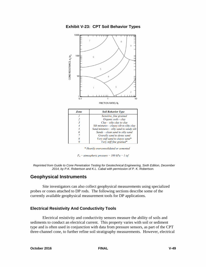
October 2016 FINAL V-49
Exhibit V-23: CPT Soil Behavior Types
Reprinted from Guide to Cone Penetration Testing for Geotechnical Engineering, Sixth Edition, December
2014, by P.K. Robertson and K.L. Cabal with permission of P. K. Robertson.
Geophysical Instruments Site investigators can also collect geophysical measurements using specialized probes or cones attached to DP rods. The following sections describe some of the currently available geophysical measurement tools for DP applications.
Electrical Resistivity And Conductivity Tools Electrical resistivity and conductivity sensors measure the ability of soils and sediments to conduct an electrical current. This property varies with soil or sediment type and is often used in conjunction with data from pressure sensors, as part of the CPT three-channel cone, to further refine soil stratigraphy measurements. However, electrical

October 2016 FINAL V-50
conductivity (EC) tools are also widely used with other DP platforms and in combination with other direct sensing tools, such as the membrane interface probe (MIP). During resistivity surveys, electrical current passes into the earth through a pair of current electrodes on the surface of the tool. A second pair of electrodes, called potential electrodes, also on the tool surface, measures the resulting difference in voltage as the current travels through the ground and the apparent resistivity is calculated. Different tools use different arrangements of current and potential electrodes, or arrays, for different applications. Examples are the dipole-dipole, Schlumberger, and Wenner arrays (U.S. EPA CLU-IN, 2015a). Exhibit V-24 presents an example of an EC probe for use with DP tooling; the tool depicted in Exhibit V-24 uses a Wenner array. Because clay units commonly carry a negative charge, they have the capacity to attract and hold onto more positively charged ions than sand. As a result, clay layers can typically be defined by high conductivity and sand by low conductivity. However, correlation of these measurements with other logging information is necessary because conductivity may be the result of other conditions, such as moisture content, soil density, mineral content, or contaminants. For example, because soil moisture content can fluctuate on a temporal scale, such as seasonally or diurnally, interpretations in the unsaturated zone are generally difficult to make (Schulmeister et al., 2003).
Exhibit V-24: Small-Diameter Direct Push EC Probe
Image courtesy of and reprinted with permission of Geoprobe Systems®.

October 2016 FINAL V-51
Nuclear Logging Tools Nuclear logging tools are geophysical instruments that either detect the natural radiation of a formation or emit radiation and measure the response of the formation. They have an advantage over other geophysical methods in being able to record usable data through metal casings. Nuclear logging tools are lowered via cable into a borehole to collect continuous or point data that is graphically displayed as a geophysical log. Interpretation of the data can help define the site stratigraphy, groundwater conditions, and, occasionally, subsurface contaminant distribution. They can be used with CPT cones, with some small-diameter probe rods, and inside the outer drive casing of dual-tube DP systems. There are primarily three nuclear methods: natural gamma, gamma-gamma, and neutron. Natural gamma tools log the amount of natural gamma particles emitted by soils. Because clays typically have a greater number of ions than sands, clays tend to have more radioactive isotopes that emit gamma radiation. Gamma-emitting minerals are also concentrated in the fine fractions. By logging the change in gamma radiation, it is often possible to characterize the site stratigraphy. Gamma-gamma tools emit gamma radiation and measure the response of the formation. Because the response is related to the density of the soil, this method can also provide information about the stratigraphy as well as the porosity of soil. Neutron methods emit neutrons into the soil and measure a response that is dependent on the moisture content. These methods can, therefore, be used to define the water table. In addition, if the stratigraphy and moisture conditions are defined with other methods, neutron logs can indicate the presence and thickness of free-phase petroleum hydrocarbons. Keys (1990) presents further discussion of nuclear logging.
Nuclear Magnetic Resonance (NMR) Logging Tools
Nuclear magnetic resonance (NMR) logging, which is based on the responses of the hydrogen protons in pore fluids such as water and NAPLs to a series of magnetic perturbations, is a relatively new approach in site characterization. In water-bearing formations, it provides information about the total moisture content, or total porosity in the saturated zone, as well as the pore size distribution, which can be used to estimate formation permeability. The petroleum industry has used NMR for characterizing petroleum reservoirs as well as oil and gas distributions for decades. However, those tools are often too expensive and over-sized for hydrological applications in groundwater wells, which typically have much smaller lengths and diameters. In the last few years, technological developments have produced an NMR logging tool that field personnel can deploy for subsurface measurements with DP dual-tube systems (Walsh et al., 2013; Knight et al., 2016). The current DP NMR tool measures soil moisture and permeability over a 0.5-meter, or 1.6 foot, depth interval. The sampling time per interval is recently improved to 3 minutes, allowing for high-resolution profiling of subsurface properties in a relatively short time in the field (Liu, 2015). Exhibit V-25 shows system components for NMR logging.

October 2016 FINAL V-52
Exhibit V-25: Small-Diameter NMR Probe And System Components
Image courtesy of and reprinted with permission of Vista Clara, Inc.
Video Imaging Tools
Although not a sensor for collecting direct geophysical measurements, downhole video imaging tools allow viewers to visually characterize lithologic properties, map significant fracture patterns, and confirm the presence of gross free-product contamination in the subsurface. Site investigators can use video imaging tools as a crosscheck against other geotechnical and geophysical sensors such as tip resistance, sleeve friction, and resistivity. Investigators are able to visually inspect ambiguous or very thin soil features or potential contaminant layers.
These systems use miniature video cameras with magnification and focusing lens systems integrated into the probe to obtain images of soil. Light-emitting diodes (LEDs) provide illumination; some systems use laser-induced fluorescence (LIF) probes to image contaminant globules. The camera sends a signal to the surface where it can be viewed in real time on a video monitor or recorded for further analysis. With 100x magnification factor, objects as small as about 20 micrometers, or 20 millionths of a meter, can be resolved on a standard 13-inch monitor. Some firms are developing algorithms to classify soils automatically from the video image (U.S. EPA CLU-IN, 2015a).
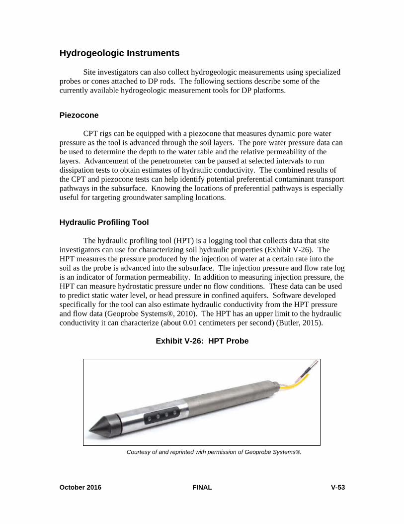
October 2016 FINAL V-53
Hydrogeologic Instruments Site investigators can also collect hydrogeologic measurements using specialized probes or cones attached to DP rods. The following sections describe some of the currently available hydrogeologic measurement tools for DP platforms.
Piezocone CPT rigs can be equipped with a piezocone that measures dynamic pore water pressure as the tool is advanced through the soil layers. The pore water pressure data can be used to determine the depth to the water table and the relative permeability of the layers. Advancement of the penetrometer can be paused at selected intervals to run dissipation tests to obtain estimates of hydraulic conductivity. The combined results of the CPT and piezocone tests can help identify potential preferential contaminant transport pathways in the subsurface. Knowing the locations of preferential pathways is especially useful for targeting groundwater sampling locations.
Hydraulic Profiling Tool The hydraulic profiling tool (HPT) is a logging tool that collects data that site
investigators can use for characterizing soil hydraulic properties (Exhibit V-26). The HPT measures the pressure produced by the injection of water at a certain rate into the soil as the probe is advanced into the subsurface. The injection pressure and flow rate log is an indicator of formation permeability. In addition to measuring injection pressure, the HPT can measure hydrostatic pressure under no flow conditions. These data can be used to predict static water level, or head pressure in confined aquifers. Software developed specifically for the tool can also estimate hydraulic conductivity from the HPT pressure and flow data (Geoprobe Systems®, 2010). The HPT has an upper limit to the hydraulic conductivity it can characterize (about 0.01 centimeters per second) (Butler, 2015).
Exhibit V-26: HPT Probe
Courtesy of and reprinted with permission of Geoprobe Systems®.

October 2016 FINAL V-54
Field personnel advance the HPT through the subsurface using traditional DP equipment. Exhibit V-27 presents the setup for the HPT. A transducer in the probe measures the pressure produced by the injection of water at a certain rate into the soil while a flow controller at the surface monitors the injection flow rate. In clays and silts, using low flow rates avoids formation alteration. As the probe advances, it relays data to the surface through a trunk line that is pre-strung in the hollow probe rods. The HPT also has an integrated EC array to simultaneously collect information on soil lithology as the probe advances.5
Slug Test Tools Slug tests involve a sudden change of the hydraulic head inside a test hole. Water will flow between the test hole and the nearby soils as a result of the initial hydraulic imbalance before the head in the hole returns to the same level as in the soils. By analyzing the transient head change in the test hole, the hydraulic conductivity of the soils can be determined.
In field applications, the initial hydraulic imbalance can be introduced by inserting or removing a physical slug, sometimes water, or a pneumatic apparatus if the casing of the hole is air-sealed. Field personnel can perform slug tests at multiple depths of a probe hole with a dual-tube rod system (Sellwood et al., 2005). Sufficient screen development is the key to get a reliable hydraulic conductivity measurement of the soils. To avoid screen clogging in slug tests, field personnel must add water to the rods before the screen is set into the soils. A pneumatic slug test kit and related analysis software have been developed and can be used to effectively perform slug tests in DP-installed wells or sampler screens (Liu, 2015).
5 A standard operating procedure (SOP) for the Geoprobe® HPT system is available for download at http://geoprobe.com/literature/hpt-sop. More information on the Geoprobe® HPT system is available at http://geoprobe.com/hpt-hydraulic-profiling-tool.

October 2016 FINAL V-55
Exhibit V-27: HPT Setup
Modified from and reprinted with permission of Geoprobe Systems®.

October 2016 FINAL V-56
Chemical Direct Sensing Tools Chemical direct sensing tools provide qualitative or semi-quantitative analysis of contaminants at a specific depth. When used over an extended area, they can rapidly provide a three-dimensional characterization of contaminant distribution. Multiple types of chemical sensors and probes are currently available for characterizing or profiling subsurface contamination using DP techniques. Some of the technologies incorporate a sensor directly into a probe that field personnel advance with the DP tooling into the subsurface. Others are sophisticated closed systems that retrieve VOCs from the subsurface and route them into an integrated instrument for analysis. The following sections describe some of the chemical direct sensing tools currently available for petroleum hydrocarbons and fuel additives. Additional sensors for inorganics and explosives are also available, but this chapter does not address these types of sensors.
Laser-Induced Fluorescence Sensor A laser-induced fluorescence sensor (LIF) is a DP tool for in-situ field screening of residual and free-phase product, such as NAPLs, in the vadose zone, saturated soils, and groundwater. The technology can provide detailed, qualitative to semi-quantitative information about the depth and horizontal extent of subsurface petroleum contamination containing polycyclic aromatic hydrocarbons (PAHs). Fuels and oils are complex mixtures of chemicals; however, LIF cannot identify individual chemicals. LIF can, however, determine relative concentrations and usually the type of product present (U.S. EPA CLU-IN, 2015b).
LIF sensors are compatible with CPT or percussion-based DP drilling technologies. Currently available LIF systems can detect gasoline, diesel, jet fuel, kerosene, motor oil, cutting fluids, hydraulic fluid, and crude oil. These systems cannot detect dissolved phase contaminants. LIF systems use a laser to send pulses of light down a fiber optic line to a probe in the subsurface. Ultraviolet (UV) light, emitted through a sapphire window on the probe, excites PAH-containing compounds in the soil, causing them to fluoresce. The resulting fluorescence, returned to the surface over a separate fiber optic line, helps field personnel to identify and measure a contaminant using specialized data acquisition equipment. Different types of PAHs fluoresce at different wavelengths, leaving a characteristic fluorescence signature. Lighter compounds such as gasoline tend to fluoresce at shorter wavelengths and heavier compounds such as diesel and motor oil fluoresce at longer wavelengths. LIF cannot detect benzene, toluene, ethylbenzene, and xylenes (BTEX) compounds because the excitation wavelength for BTEX is incompatible with fiber optics.6 Exhibit V-28 shows how LIF screening tools take advantage of the fluorescence of PAHs for detecting petroleum contamination in the subsurface.
6 More information on this technology is available from Dakota Technologies, Inc. at http://www.dakotatechnologies.com/intro-to-lif.

October 2016 FINAL V-57
Exhibit V-28: Fluorescence Of Crude Oil And Diesel
Reprinted from http://www.dakotatechnologies.com/intro-to-lif
with permission of Dakota Technologies. There are several LIF systems currently available, which primarily differ in the
laser used to excite the PAHs and whether the DP platform used to advance the equipment is CPT or percussion-driven. Data from many systems are compatible with three-dimensional visualization software. LIF data quality is sufficient for qualitative screening, and site investigators should consider relative intensities as quantitative screening-level data only. Site-specific detection limits vary from levels of 10 to 1,000 milligrams per kilogram (U.S. EPA CLU-IN, 2015b).
Exhibit V-29 shows the components of Dakota Technologies, Inc. Ultra-Violet
Optical Screening Tool (UVOST®) LIF system; Exhibit V-30 depicts a typical log of data obtained using the UVOST®. The callouts in the left side of the exhibit show a waveform measured and stored by the LIF at a particular depth. The four peaks are due to fluorescence at four wavelengths, also known as channels. Each channel has an associated color. The main plot in the depicted log is signal, or total fluorescence, versus depth where signal is relative to the reference emitter (RE). To find the percent RE, divide the total area of the waveform by the total area of the reference emitter. The fill color in the main plot is based on relative contribution of each channel’s area to the total waveform area. In the example data, a detection of motor oil is shown in orange at a shallow depth, and diesel is shown in green at a greater depth.
Advantages of LIF:
• Can detect residual and free-phase product containing PAHs in both unsaturated and saturated zones
• One type of probe may advance rapidly into the subsurface at almost an inch per second under favorable soil conditions

October 2016 FINAL V-58
• Compatible with both CPT and percussion-based DP technologies
• Continuous logging with depth
• Data acquisition and analysis in real time
Limitations of LIF:
• Does not respond to dissolved phase VOCs or semi-volatile organic compounds (SVOCs), including BTEX
• Cannot detect chlorinated solvent dense non-aqueous phase liquid (DNAPL)
• Soil matrix may affect fluorescence; sand and gravel have a response about 10 times higher than clay and silt
• False positives are possible for materials such as sea shells, peat, wood, calcareous sands, and sewer lines
Additional information on LIF, including a comparison of strengths and limitations of some of the currently available LIF systems, is available on EPA’s CLU-IN website at http://cluin.org/characterization/technologies/lif.cfm.
Exhibit V-29: LIF System Components
Reprinted from www.dakotatechnologies.com/services/uvost with permission of Dakota Technologies.
Control Computer Oscilloscope
Laser
Remote Display
Breakout Box
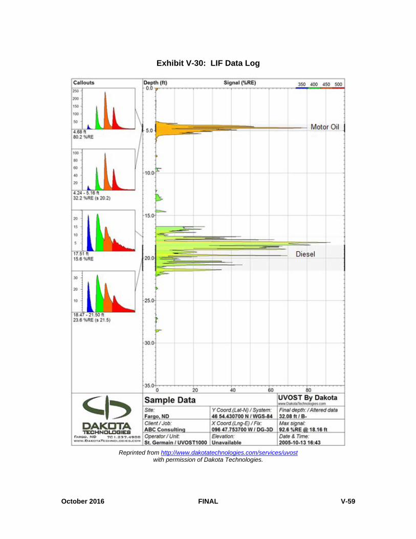
October 2016 FINAL V-59
Exhibit V-30: LIF Data Log
Reprinted from http://www.dakotatechnologies.com/services/uvost
with permission of Dakota Technologies.

October 2016 FINAL V-60
Fuel Fluorescence Detector Another induced fluorescence technology, the fuel fluorescence detector (FFD), is very similar to LIF except that it generally uses a mercury lamp or LED as its light source and the light is located in the probe at the sapphire window. This lamp provides either a continuous source of light or a pulsed source, similar to the LIF. Although downhole detectors are available, fluorescence intensities from the soil are generally returned to the surface for measurement via fiber optic cable.7 The data acquisition system generally reads total fluorescence. Some vendors have filtering capabilities to limit wavelength reception to their detectors that allows some differentiation between contaminant types. Strengths and limitations are similar to those of LIF.
One vendor has also developed a logging tool that uses a camera supplied with both UV and visible light to capture images of soil every 0.05 feet as the tool is advanced.8 The tool’s image analysis calculates a fluorescence area of each image for use in a log of fluorescence versus depth.
Membrane Interface Probe A membrane interface probe, or MIP, is a semi-quantitative, field-screening DP tool for detecting VOCs and some SVOCs in subsurface soil and groundwater (Exhibit V-31). MIP technology uses heat to volatilize and mobilize contaminants for sampling at the surface. The results produced by an MIP at any location are relative and, depending on data quality objectives, site investigators may need to supplement them with more definitive sampling data. However, results from the MIP can qualitatively distinguish between areas of low, medium, and high total VOC contamination at a site. Investigators can then use this information to limit future sampling efforts in clean areas or focus sampling efforts on areas with more significant contamination.
Exhibit V-31: Membrane Interface Probe
Image courtesy of and reprinted with permission of Geoprobe Systems®. 7 An FFD probe, developed by Vertek®, detects and logs UV-induced hydrocarbon fluorescence in soil downhole, without the need for fiber optic cable. For more information visit, http://www.vertekcpt.com/environmental-investigation-products. 8 The Optical Image Profiler (OIP), developed by Geoprobe Systems® and released in 2016, is an in-situ logging tool capable of detecting and logging UV-induced hydrocarbon fluorescence in soil. For more information, visit http://geoprobe.com/oip.

October 2016 FINAL V-61
The MIP is compatible with CPT and percussion-based DP technologies. An MIP system consists of a stainless steel probe, a trunkline to the surface, a controller, a data acquisition system, and a gaseous phase detector (Exhibit V-32). The MIP works by heating the surrounding soils to about 100° to 120° Celsius (C), which promotes diffusion of VOCs through a semi-permeable membrane in the probe. Volatilized contaminants enter the probe through this membrane and a continuous draft of an inert carrier gas, such as nitrogen or helium, transports the contaminants through a trunkline to one or several gaseous phase detectors at the surface (Exhibit V-33). It takes about 35 seconds for the carrier gas stream to travel through about 100 feet of inert tubing and reach the detectors used in the system. The detectors feed the results to the data acquisition system, which can display them as a real-time graph of detected contamination versus depth of probe penetration.9
Exhibit V-32: MIP System Components
Reprinted, with permission, from ASTM D7352 – 07 (Reapproved 2012), Standard Practice for Direct Push Technology for Volatile Contaminant Logging with the Membrane Interface Probe (MIP), copyright ASTM International, 100 Barr Harbor Drive, West Conshohocken, Pennsylvania 19428. A copy of the complete
standard may be obtained from ASTM International (http://www.astm.org). 9 An SOP for the MIP developed and manufactured by Geoprobe Systems® is available for download at http://geoprobe.com/literature/mip-logging-sop.

October 2016 FINAL V-62
Exhibit V-33: MIP Principal of Operation
Image courtesy of and reprinted with permission of Geoprobe Systems®.
The MIP’s detection limits depend on the soil type, temperature, and detector used. Gaseous phase detectors commonly used with an MIP include the PID, the FID, and the halogen specific detector (XSD). When applied in series, each detector provides sensitivity to a particular group or type of contaminant. The XSD is highly specific to halogenated compounds. The PID provides sensitivity to aromatic compounds, such as BTEX, as well as confirmation of chlorinated ethylene compounds detected by the XSD. The FID is a general detector useful for hydrocarbon detection but it can also confirm high concentrations of compounds observed on the other two detectors. When a greater degree of speciation is required, analytical devices used with the MIP may include an ion trap mass spectrometer (ITMS), gas chromatograph (GC), or GC/mass spectrometer (GC/MS).
Use of MIPs in combination with other direct sensing technology, such as EC
sensors or HPTs, help correlate contamination to soil stratigraphy and hydraulic characteristics.10 Exhibit V-34 illustrates the graphical output of a typical MIP/EC log
10 Geoprobe Systems® developed a combined MIP and HPT probe known as the MiHPT. The MiHPT detects volatile contaminants with the MIP, measures soil electrical conductivity with a standard dipole

October 2016 FINAL V-63
using FID as the gaseous phase detection device at the surface. In general, zones of lower EC indicate coarser-grained, more permeable materials. The log in Exhibit V-34 shows finer grained soils at shallower depths before transitioning to coarser grained material at about 7 meters below grade. A response from the FID was observed at this transition to more permeable materials.
Exhibit V-34: Example Log For MIP/EC Combination Using FID
Image courtesy of and reprinted with permission of Geoprobe Systems®.
As with the other direct sensing tools described in this chapter, there are strengths and limitations of MIP technology. Advantages of MIP:
• Can determine the presence or absence of subsurface VOC contamination and relative degree of contamination in both the unsaturated and saturated zones.
• Can advance rapidly at a rate of about 1 foot per minute.
• Acquires and analyzes data in near real time.
array, and measures HPT injection pressure using the same down-hole transducer as the Geoprobe® stand-alone HPT system (http://geoprobe.com/mihpt).

October 2016 FINAL V-64
• In combination with other probes or sensors, can provide simultaneous logging of
precise three-dimensional delineation of source and plume areas, which supports on-site decision-making.
Limitations of MIP:
• Standard MIP typically cannot detect methyl tertiary butyl ether (MTBE), due to its chemical structure and solubility. However, new low-level MIP (LL-MIP) technology may improve MTBE detection (Pipp, 2012).
• Detection limits depend on soil type, temperature, and detector used. Finer-grained soils tend to yield lower detection limits than coarser soils. Limiting factors include signal to noise ratio, length of trunkline, and membrane wear (U.S. EPA CLU-IN, 2015c).
• Cannot readily distinguish between high concentration soil levels and free-phase NAPL (ITRC, 2015).
• Contaminant carryover likely in NAPL or high-concentration zones (ITRC, 2015). When an MIP advances through high-concentration zones, the MIP profile may show residual responses that taper off after the next 5 to 10 feet. A portion of the diffusing contaminants may adsorb onto the membrane material or be retained in the trunkline, which takes time to clear off or flush out (Geoprobe Systems®, MIP Frequently Asked Questions [FAQs]).
• May not work well in cold conditions due to potential freezing of water vapor in the trunkline; however, a heated trunkline option from some vendors is available.11
• Determining sample depth when the MIP is in a near-continuous operating mode is more difficult the deeper the instrument is driven.
• The sample size or area influenced by the heated membrane has not been studied, but is affected by temperature of the membrane, the type of surface media such as vadose zone soils or saturated soils, and contact time between membrane and soils. Because the sample mass and volume are not known, data from an MIP should be considered estimates (Myers, Davis, and Costanza, 2002).
11 Geoprobe Systems® offers a heated trunkline. More information is available at http://geoprobe.com/literature/mip-heated-trunkline.

October 2016 FINAL V-65
Site Characterization And Analysis Penetrometer System Hydrosparge
The Site Characterization and Analysis Penetrometer System (SCAPS), developed by the Tri-Services—comprised of the U.S. Army, U.S. Navy, and U.S. Air Force—is a truck-mounted CPT platform that also contains a number of analytical tools and sensors, one of which is the Hydrosparge (Exhibit V-35). The Hydrosparge is similar to the MIP system in that it extracts VOCs from groundwater and brings them to the surface for analysis via a closed system. It differs from the MIP in two ways. Unlike the MIP, the Hydrosparge is active and physically purges VOCs from the sample interval rather than allowing them to passively diffuse into the sampler. In addition, the Hydrosparge is only able to sample one discrete interval; field personnel must retract the probe prior to advancing to the next depth. Coarse sands and gravels can significantly clog the screen within the sampler as the distance below the water table increases. The Hydrosparge does not incorporate a lithologic sensor. Site investigators should select sampling intervals based on separate pushes with CPT sensors at the desired sample location.
Exhibit V-35: SCAPS Hydrosparge Schematic
Image courtesy of J. Ballard, 2015. Reprinted with permission of the U.S. Army Engineer Research and
Development Center – Environmental Laboratory.

October 2016 FINAL V-66
The Hydrosparge system integrates a customized 2-inch CPT probe with a small sampling port, a Teflon® transfer line for carrier gas, and an aboveground direct sampling ion trap mass spectrometer (DSITMS) detector in the truck. The Hydrosparge VOC sensor uses a commercially available DP groundwater sampling tool to access the groundwater (Davis et al, 2001).
The groundwater sampler is pushed to the desired depth and the push rods are retracted, exposing the screen to the groundwater. After the water level reaches equilibrium, which generally takes about 15 to 20 minutes depending on hydrogeologic conditions, field personnel lower the in-situ sparge module about 1.5 feet below the groundwater surface. Using helium gas, the sparge module purges the VOC analytes in-situ from the groundwater to the DSITMS system in the truck, where field personnel can analyze VOCs in real time.
Advantages of SCAPS Hydrosparge:
• Can determine the presence or absence of VOCs in groundwater; DSITMS can identify specific analytes and estimate concentrations
• Acquires and analyzes data in near real time.
Limitations of SCAPS Hydrosparge:
• Currently only available with a limited number of government SCAPS platforms
• SCAPS 20-ton vehicle has access limitations
• Transfer lines are subject to high-level contamination carryover, though contamination can be minimized with line purging
• Subject to limitations of DSITMS
• Can only collect one sample per push
• Does not incorporate additional lithologic sensors
SCAPS Thermal Desorption Sampler
The SCAPS thermal desorption sampler (TDS) is similar in principle and practice to the MIP and SCAPS Hydrosparge systems, but is specifically geared toward characterization of vadose zone soils in situ. The TDS system is a closed system that draws VOCs directly from the subsurface for analysis by a surface detector.
The TDS consists of a custom soil probe, carrier gas lines and supply, an analytical trap, and a DSITMS detector (Myers et al., 1999). The sample probe

October 2016 FINAL V-67
incorporates an internal piston and a heated thermal sample chamber connected to the carrier gas lines (Exhibit V-36). The TDS does not incorporate a lithologic sensor. Site investigators must select sampling intervals based on separate pushes with CPT sensors at the desired sample location.
Operating the TDS is based on the capture of a known volume of soil. Field personnel push the TDS to a target depth and an interior rod retracts the penetrometer tip, which locks into the top of the sample chamber. Field personnel then push the probe further into the soil, collecting a 5-gram soil plug in the sample chamber. The TDS heats the soil plug, releasing the VOC gases from the soil. A carrier gas then transports the resulting vapors to the surface, where they are trapped on an adsorbent media. The trap is then thermally desorbed into the onboard, field-portable DSITMS, where VOCs are analyzed in near real time.
Exhibit V-36: Schematic Of TDS Probe In Ready-To-Sample Position
Myers et al., 1999. Reprinted with permission of the U.S. Army Engineer Research and Development
Center –Environmental Laboratory.

October 2016 FINAL V-68
After analysis, field personnel can remove the soil from the sample chamber by reseating the piston into the drive position. They then must heat and purge the sample chamber to remove residual contamination before repeating the process. This allows for screening of multiple depths during a single push.
Field personnel may also use the TDS as a vapor sampler in the vadose zone by applying a vacuum to the transfer line and drawing soil vapors to the surface where they are trapped, desorbed, and analyzed by the DSITMS in near real time.
Advantages of SCAPS TDS:
• Can determine the presence or absence of VOCs in soil; DSITMS can identify specific analytes and estimate concentrations
• Allows for collection of multiple samples per borehole
• Acquires and analyzes data in near real time
Limitations of SCAPS TDS:
• Currently only available with a limited number of government SCAPS platforms
• SCAPS 20-ton vehicle has access limitations
• Poor sample recovery in some soil conditions
• Transfer lines are subject to high-level contamination carryover, though this can be minimized with line purging
• Subject to limitations of DSITMS
• Potential for interference from water vapor in long lengths of the transfer line in very cold conditions

October 2016 FINAL V-69
Discussion And Recommendations For Specialized Measurement And Logging Instruments Specialized measurement and logging tools are a growing component group of DP tooling that are ideal for rapid site characterization in unconsolidated sediments. DP sensing and logging tools can provide information about soil stratigraphy, depth to groundwater, hydraulic conductivity, and other aquifer properties, as well as determine the presence and extent of subsurface contamination. Continuous logs of subsurface conditions are particularly valuable because they help develop a three-dimensional CSM. These data are also gathered and analyzed in real time or near real time, which supports on-site decision making by site investigators. DP sensing and logging instruments collect data without the many requirements associated with sample management and while generating minimal IDW. This approach potentially allows the site investigator to conduct a more rapid and detailed assessment at a lower overall cost than one could achieve with more traditional methods such as drill rigs and off-site laboratories. Specialized measurement and logging instruments provide objective information, but the interpretation of measurements may still be subjective. Data provided by direct sensing tools are generally considered screening-level data, requiring correlation with actual samples. In addition, while geophysical logging methods for defining stratigraphy produce reliable information about the primary lithology of the strata, they provide very little data regarding secondary soil features like desiccation cracks, fractures, and root holes. In silts and clays, these secondary soil features may control the movement of contaminants into the subsurface and may greatly influence the options for active remediation. At interbedded sites where defining macropores is important, continuous soil coring may be a better alternative. As noted in the previous sections, there are also limitations associated with individual chemical sensing tools. Exhibit V-37 presents a summary of in-situ specialized measurement and logging instruments used with DP technologies.

October 2016 FINAL V-70
Exhibit V-37: Summary Of Direct Push Specialized Measurement And Logging Tools
Tool Or Sensor DP Platform Application Geotechnical
Three-Channel Cone CPTa Measures tip resistance, sleeve resistance, and inclination. Used to determine soil behavior types, which can be correlated with boring logs.
Geophysical
EC Probe DPb Measures the ability of soils to conduct an electrical current. Used to refine soil stratigraphy where electrically conductive clays are the dominant control.
Nuclear Logging Probe DP Depending on type, either detects natural radiation of a formation or emits radiation and measures the response of the formation. Used to define site stratigraphy where electrically conductive clays are the dominant control; groundwater conditions; and, occasionally, subsurface contaminant distribution.
NMR DP Provides information about the total moisture content or total porosity in the saturated zone, as well as pore size distribution, which can be used to estimate soil permeability.
Video Imaging Probe DP Obtains images of the subsurface. Used for visual characterization of lithologic properties, mapping of significant fracture patterns, and confirmation of the presence of gross free-product contamination.
Hydrogeologic
Piezocone CPT Measures the rate at which the water pressure returns to static conditions. Can be used to estimate hydraulic conductivity and the position of the water table. The quality of hydraulic conductivity is low and can only be used as screening-level data.
HPT DP Measures the pressure produced by the injection of water at a certain rate into the soil. Can be used to estimate hydraulic conductivity and the position of the water table.
Slug Testing Tools DP Measures changes in hydraulic head introduced by the insert or removal of a physical slug (sometimes water), or a pneumatic apparatus if the casing of the hole is air-sealed; data are used to determine the hydraulic conductivity of the nearby soils.
Chemical
LIF and FFD Probes DP Detect fluorescence of PAHs in residual and free-phase product in vadose and saturated soils and groundwater. Used to determine the presence and distribution of subsurface petroleum contamination.
MIP DP Detects VOCs and some SVOCs in soil and groundwater, using a variety of gaseous detectors such as PID, FID, etc. Used to determine the presence and distribution of volatile contamination.
SCAPS Hydrosparge SCAPS CPT Detects VOCs in groundwater, using DSITMS. Used to determine the presence and distribution of VOC contamination in groundwater. Government SCAPS platform.
SCAPS TDS SCAPS CPT Detects VOCs in vadose zone soils, using DSITMS. Government SCAPS platform. Notes: a – CPT; available with cone penetrometer testing equipment only. b – DP; available with CPT and other DP platforms, including percussion hammer.

October 2016 FINAL V-71
Methods For Sealing Direct Push Holes One of the most important issues to consider when selecting DP equipment is the method for sealing probe holes. Because any hole can act as a conduit for contaminant migration, proper sealing of probe holes is essential for ensuring that site assessment activity does not contribute to spreading contaminants. Proper sealing is also essential to prevent hazards at the surface. The issue of sealing holes and preventing cross-contamination is not an issue unique to DP technology. Conventionally drilled holes also require proper abandonment; in fact, they may pose an even greater risk of cross-contamination because the larger diameter holes provide an even better conduit for contaminants. Many of the methods for sealing holes apply to both DP and conventional drilling methods. However, because DP probe holes are small in diameter, they provide some additional challenges. The selection of appropriate sealing methods depends on site-specific conditions. For example, at UST sites where LNAPLs are perched on clay layers in the unsaturated zone, intrusive sampling can facilitate deeper migration of contaminants. In addition, where interbedded formations create multiple aquifers, unsealed holes may allow for the vertical migration of dissolved contaminants into otherwise protected lower aquifers. The primary objective of sealing is to prevent preferential migration of contaminants through the probe hole. At a minimum, the vertical permeability of the sealed hole should not be any higher than the natural vertical permeability of the soils. In some soils, preferential migration may be prevented without using sealants. For example, in some homogeneous sands, the hole will cave immediately as field personnel withdraw the probe, re-establishing the original permeability of the subsurface materials. Unfortunately, it is usually impossible to verify that holes have sealed completely with such natural collapse methods. As a result, more proactive methods of probe hole sealing are generally necessary. A typical method for sealing probe holes involves use of a grout made of neat cement, which is a mixture of portland cement and water; a bentonite slurry; or a combination of the two. Use of dry products, such as bentonite granules, pellets, or chips, is also possible, but may pose problems because of the small diameter of probe holes. Dry bentonite products absorb moisture quickly and expand, often before reaching the bottom of the hole, resulting in bridging and an incomplete seal. There are three primary methods for sealing DP holes (Exhibit V-38):
• Surface pouring • Re-entry grouting • Retraction grouting

October 2016 FINAL V-72
The following text summarizes the advantages, limitations, and applicability of these methods. ASTM D6001 – 05 (ASTM, 2012) and Lutenegger and DeGroot (1995) provide additional information on probe hole abandonment techniques.
Surface Pouring The simplest method for sealing a hole in stable materials is to pour grout, dry granular bentonite, or bentonite pellets directly into the open hole (Exhibit V-38a). This method is sometimes referred to as gravity pouring. This method is generally only acceptable if the hole is shallow, less than about 10 feet bgs, stays open, and does not intersect the water table. This method is the least desirable because small probe holes commonly cause bridging of grout and dry bentonite products before reaching the bottom, leaving large open gaps in the hole. Field personnel can often avoid or minimize this by slowly adding the grout and stopping every few feet to measure, tamp the grout with small metal or plastic rods, and add water to hydrate. Use the amount of added water according to manufacturer specifications.
Re-Entry Grouting Re-entry grouting seals a DP hole after field personnel withdraw the rods. This method prevents bridging of grout and re-opens collapsed sections of the hole. One method is to pump grout or pour dry material through a flexible or rigid tube placed at the bottom of the open hole, a method also called bottom-up grouting (Exhibit V-38b). Usually, field personnel use a schedule 40 or 80 Type I PVC pipe for this tool, known as a tremie pipe. To prevent bridging, field personnel must keep the tremie pipe below the surface of the slurry as the grout fills the hole. Flexible or rigid tremie pipes may be difficult or impossible to use if the probe hole collapses. A flexible tremie pipe may not be able to penetrate bridged soil and a rigid tremie pipe may become plugged. If tremie pipes are not appropriate for sealing probe holes, re-entry with probe rods and an expendable tip is a possible alternative (Exhibit V-38c). This method allows the rods to be pushed through soil bridges to the bottom of the probe hole. Field personnel then withdraw the probe rods slightly, and knock out the expendable tip by lowering a small diameter steel rod inside the rods or blowing it off by applying pressure with the grout pump. Field personnel can then pump grout through the rods as they are withdrawn from the hole. Re-entry grouting with DP rods and expendable tips usually results in adequate seals, however, this method is not always reliable. On occasion, DP rods may not follow the original probe hole, but instead create a new hole adjacent to the original one. If this happens, sealing the original hole may be impossible. This situation is rare but may be a problem when sampling in:
• Soft silts or clays that overlie a denser layer • Cobbly or boulder-rich sediments overlying a denser clayey confining layer • Loose homogeneous sands that overlie a clayey layer

October 2016 FINAL V-73
Retraction Grouting Retraction grouting is a method in which field personnel seal the hole as they withdraw the DP rods and tooling. The rods act as a tremie pipe for neat cement grout or a bentonite slurry that is either poured or pumped down the hole, ensuring a complete seal of the probe hole. Retraction grouting is possible with single-rod systems; however, the sampling method used with a single-rod system may limit its application. For example, retractable tip and exposed screen soil-gas samplers do not allow retraction grouting. With cased or dual-tube systems, retraction grouting is possible in most situations. Retraction grouting is not possible with DP NMR. There are two methods for using retraction grouting with single-rod systems. One method can be used when expendable tips or well screens are attached to the probe rod for soil-gas or groundwater sampling. Grouting with these sampling tools occurs as described in re-entry grouting with expendable tips, if the sampling tool has a grout plug at the bottom that allows ground passage. With well screens, the screen must be expendable. With both tools, field personnel pour or pump grout as they retrieve the rods. Other sampling tools attached to single-rod systems typically do not allow retraction grouting because the sampling tools seal the end of the rods. However, there are some exceptions, described below. CPT systems allow a second method of retraction grouting with single-rod systems by a small-diameter grout tube that extends from the cone to the ground surface inside the CPT rods. One variation uses an expendable tip that is detached from the cone by the pressure of the grout being pumped through the tube (Exhibit V-38d). Another variation of this method consists of pumping the grout through ports in a friction reducer instead of the cone. One vendor recently developed a grout adapter that can attach directly to a logging instrument, such as an MIP or HPT, on a single-rod system that operates in a similar manner (Exhibit V-39).12 The adaptor uses a separate line that extends down through the DP rods. After obtaining the needed data from the logging instrument, field personnel retract the tool about one foot and then pump water through the line to dislodge a grout plug in the adapter. Field personnel can then pump grout down the hole. With cased, or dual-tube, systems, retraction grouting is unaffected by the type of sampling tools employed and withdrawn before grouting, because the outer casing can maintain the integrity of the hole after sampling. As a result, proper use of cased systems can ensure complete sealing of DP holes.
12 Geoprobe Systems® developed the Direct Image® 2.25-inch Grout Sub in 2014 for use with their line of direct imaging tools, for example MIP, HPT. More information is available at http://geoprobe.com/articles/grouting-made-easy-direct-image-225-grout-sub.

October 2016 FINAL V-74
Exhibit V-38: Methods For Sealing Direct Push Holes
Reprinted from Techniques for Sealing Cone Penetrometer Holes. 1995.
Canadian Geotechnical Journal. Vol. 32, No. 5: 880-891 by A.J. Lutenegger and D.J. DeGroot. ©Canadian Science Publishing or its licensors.

October 2016 FINAL V-75
Exhibit V-39: Geoprobe® Grout Sub
Image courtesy of and reprinted with permission of Geoprobe Systems®.
Discussion And Recommendations For Sealing Direct Push Holes Surface pouring may be acceptable in shallow holes less than 10 feet bgs that do not penetrate the water table and in which the subsurface materials are cohesive. This method requires considerable care to be effective because the small size of DP holes increases the probability of grout or dry bentonite bridging and not completely sealing. Re-entry grouting is the next best alternative and is often adequate for providing a completely sealed hole. Re-entry grouting may be appropriate if deflection of probe rods is not likely, if NAPLs are not present, or if NAPLs are present but do not pose a risk of

October 2016 FINAL V-76
immediately flowing down the open hole. If LNAPLs are present, the risk of cross-contamination will depend on many other factors, such as soil grain size and quantity of LNAPLs. Hence, while re-entry grouting may at times effectively prevent cross-contamination in source areas, use it judiciously. Retraction grouting is the most effective sealing method for preventing cross-contamination. It is required if:
• LNAPL is commingled with DNAPL • Sufficient LNAPLs are present to rapidly flow down an open hole • A perched, contaminated water lens is encountered • Deflection of probe rods may occur
Exhibit V-40 presents a summary of sealing methods.
Exhibit V-40: Summary Of Direct Push Hole Sealing Applications
Site Conditions Surface Pouringa
Re-entry Grouting
Retraction Grouting
NAPLs Not Present
Cohesive Soils X X X
Soils Collapse X X
NAPLs Present
Cohesive Soils Xb Xb X Soils Collapse Xb X
Deflection of Probe Rod May Occur X
Notes: a – This method should not be used if the probe hole intersects the water table. b – These methods may not be used if there is an immediate danger of NAPLs flowing down
the open hole, that is large quantities of LNAPLs are perched on clay layers.

October 2016 FINAL V-77
References (Alphabetical) American Petroleum Institute. 2005. Collecting and Interpreting Soil Gas Samples from the Vadose Zone, a Practical Strategy for Assessing the Subsurface Vapor-to-Indoor Air Migration Pathway at Petroleum Hydrocarbon Sites. API Publication 4741. Washington, D.C. http://www.api.org/oil-and-natural-gas/environment/clean-water/ground-water/vapor-intrusion/vi-publication/assessing-vapor-intrusion.
The document focuses on the collection of soil-gas samples for assessing the significance of the subsurface-vapor-to-indoor-air exposure pathway. Chapter 5 addresses soil-gas sample collection techniques, including probes installed with direct push (DP) techniques.
American Petroleum Institute. 2000. Strategies for Characterizing Subsurface Releases of Gasoline Containing MTBE. API Publication 4699. Washington, D.C. http://www.api.org/oil-and-natural-gas/environment/clean-water/ground-water/oxygenates/site-characterization.
This report includes a chapter on DP sampling technologies relevant to methyl tertiary butyl ether (MTBE) site assessments.
Amos, R.T. and D.W. Blowes. 2008. Versatile Direct Push Profiler for the Investigation of Volatile Compounds Near the Water Table. Water Resources Research, Vol. 44, No. 4, W00D17. http://onlinelibrary.wiley.com/doi/10.1029/2008WR006936/abstract.
The study presents the design of a DP profiler capable of collecting gas samples from the vadose zone and groundwater samples in one DP hole, collecting samples very close to the water table, and collecting samples from deep aquifers while preserving sample integrity of volatile components. Amos and Blowes evaluated the sampler in the laboratory and at a field site.
AMS, Inc.
http://www.ams-samplers.com/category.cfm?CNum=108. Manufacturer of DP rigs, called PowerProbes. The link addresses applications and tooling for the PowerProbe.
Applied Research Associates, Inc. 2004. Enhanced Access Penetration System (EAPS) Draft Technical Final Report. http://www.triadcentral.org/tech/documents/enhanced_dp_evaluation_report.pdf.
This study evaluates an enhanced access penetration system that aims to extend cone penetrometer (CPT) depth, conducts real-time sample collection and analysis, and contains drilling waste material.
ASTM D1586 – 11. 2011. Standard Test Method for Standard Penetration Test (SPT) and Split-Barrel Sampling of Soils. ASTM International, West Conshohocken, Pennsylvania, DOI: 10.1520/D1586-11. http://www.astm.org/Standards/D1586.htm.
This test method describes the procedure, generally known as the standard penetration test (SPT), for driving a split-barrel sampler to obtain a representative

October 2016 FINAL V-78
disturbed soil sample for identification purposes and measure the resistance of the soil to penetration of the sampler.
ASTM D6001 – 05. 2012. Standard Guide for Direct-Push Groundwater Sampling for Environmental Site Characterization, ASTM International, West Conshohocken, Pennsylvania, DOI: 10.1520/D6001-05R12. http://www.astm.org/Standards/D6001.htm.
This ASTM guide describes various sampling techniques for collection of groundwater samples from DP boreholes. Field test methods include installation of temporary well points and insertion of water samplers using a variety of insertion methods.
ASTM D6282 / D6282M – 14. 2014. Standard Guide for Direct Push Soil Sampling for Environmental Site Characterizations. ASTM International, West Conshohocken, Pennsylvania, DOI: 10.1520/D6282_D6282M-14. http://www.astm.org/Standards/D6282.htm.
This ASTM guide summarizes soil sampling techniques, including advantages and disadvantages, for single-tube and double-tube DP systems.
ASTM D6724 – 04. 2010. Standard Guide for Installation of Direct Push Groundwater Monitoring Wells. ASTM International, West Conshohocken, Pennsylvania, DOI: 10.1520/D6724-04R10. http://www.astm.org/Standards/D6724.htm.
This ASTM guide describes various DP groundwater monitoring wells and provides guidance on their selection and installation for obtaining representative groundwater samples and monitoring water table elevations. This guide also discusses some groundwater sampling devices that field personnel can permanently emplace as monitoring wells.
ASTM D6725 – 04. 2010. Standard Practice for Direct Push Installation of Prepacked Screen Monitoring Wells in Unconsolidated Aquifers. ASTM International, West Conshohocken, Pennsylvania, DOI: 10.1520/D6725-04R10. http://www.astm.org/Standards/D6725.htm.
This ASTM practice provides the user with information on the appropriate methods and procedures for installing prepacked screen monitoring wells by DP methods.
ASTM D7352 – 07. 2012. Standard Practice for Direct Push Technology for Volatile Contaminant Logging with the Membrane Interface Probe (MIP). ASTM International, West Conshohocken, Pennsylvania, DOI: 10.1520/D7352-07R12. http://www.astm.org/Standards/D7352.htm.
This standard practice describes a method for rapid delineation of volatile organic compounds, or VOCs, in the subsurface using an MIP.
ASTM D7648 – 12. 2012. Standard Practice for Active Soil Gas Sampling for Direct Push or Manual-Driven Hand-Sampling Equipment. ASTM International, West Conshohocken, Pennsylvania, DOI: 10.1520/D7648-12. http://www.astm.org/Standards/D7648.htm.

October 2016 FINAL V-79
This practice details the collection of active soil-gas samples using a variety of sample collection techniques with tooling associated with DP technology or manual-driven hand sampling equipment, for the express purpose of conducting soil-gas surveys.
Ballard, J. 2015. Site Characterization and Analysis Penetration System (SCAPS). U.S. Army Research and Development Center. Vicksburg, Mississippi.
J. Ballard provides photographs and schematics of the SCAPS Hydrosparge and thermal desorption sampler. The exhibits are courtesy of the U.S. Army Engineer Research and Development Center – Environmental Laboratory.
BAT® Groundwater Monitoring Systems.
http://www.bat-gms.com/bat-groundwater-monitoring-and-testing.asp. Manufacturer of sealed-screen groundwater samplers. The link describes the BAT® system and its functions.
Bernsten, J. 2014. Comprehensive Site Characterization, Innovative Technologies, and the Value of Complete Assessment. Presented to the Association of State and Territorial Solid Waste Management Officials (ASTSWMO) at the 2014 LUST and State Fund-Financial Responsibility Workshop. Environmental Compliance Services, Inc. http://www.astswmo.org/Files/Meetings/2014/2014-LUST_SF-FR_Workshop/Presentations/6_23_14/Bernsten-2014-05-20-ECS-ASTSWMO%20Presentation.pdf.
This presentation addresses several real-time site characterization tools, including the electrical conductivity (EC) logging tool and the hydraulic profile tool (HPT) for hydrogeology characterization and the MIP and the ultra-violet optical screening tool (UVOST®) for contaminant characterization.
Berzins, N.A. 1993. Use of the Cone Penetration Test and BAT® Groundwater Monitoring System to Assess Deficiencies in Monitoring Well Data. Proceedings of the 6th National Outdoor Action Conference. National Ground Water Association, Columbus, Ohio. http://info.ngwa.org/gwol/pdf/920156435.PDF.
The study compares CPT and BAT® groundwater monitoring system data to existing borehole and monitoring well data from two field investigations. Results found that the CPT profiles more accurately defined stratigraphic changes. Depth discrete groundwater sampling using the BAT® system also found that previous groundwater data reflected a composite value and not depth-discrete values.
BESST, Inc. http://besstinc.com/index.php/simulprobes/. BESST manufactures groundwater sampling equipment, including the multi- media samplers MaxiProbe® and MiniProbe®. BP Corporation of North America, Inc. and the Underground Storage Tank (UST) Programs of the U.S. Environmental Protection Agency’s Regions 4 and 5. 2002. Monitoring Well Comparison Study: An Evaluation of Direct-Push Versus Conventional

October 2016 FINAL V-80
Monitoring Wells. BP Corporation of North America, Inc., Warrenville, Illinois. https://www.epa.gov/ust/monitoring-well-comparison-study-evaluation-direct-push-versus-conventional-monitoring-wells.
The study found that, provided wells are properly developed, all measurements from DP monitoring wells are equivalent to measurements from conventional monitoring wells.
Bujewski, G. and B. Rutherford. 1997. The Site Characterization and Analysis Penetrometer System (SCAPS) Laser-Induced Fluorescence (LIF) Sensor and Support System: Innovative Technology Verification Report. EPA/600/R-97/520. Environmental Protection Agency, Washington D.C. http://www.clu-in.org/characterization/technologies/lif.cfm.
The report documents demonstration activities and presents and evaluates the demonstration data to verify the performance of the SCAPS LIF sensing technology relative to developer claims.
Butler, J.J., Jr. Kansas Geological Survey, University of Kansas, Lawrence, Kansas. 2015. Peer Review comments received August 30, 2015 on Chapter V Direct Push Technologies of Expedited Site Assessment Tools for Underground Storage Tank Sites: A Guide for Regulators, submittal version dated August 12, 2015. Butler, J.J., Jr. 2002. A Simple Correction for Slug Tests in Small-Diameter Wells. Ground Water. Vol. 40, No. 3: 303-307. https://www.researchgate.net/publication/11351506_A_Simple_Correction_for_Slug_Tests_in_Small-Diameter_Wells.
This publication describes a simple procedure for correcting hydraulic conductivity (K) estimates obtained from slug tests performed in small-diameter installations screened in highly permeable aquifers.
Butler, J.J., J.M. Healey, G.W. McCall, E.J. Garnett, and S.P. Loheide, II. 2002. Hydraulic Tests with Direct Push Equipment. Ground Water. Vol. 40, No. 1: 25-36. http://geoprobe.com/literature/hydraulic-tests-with-direct-push-equipment-technical-paper.
The study investigates the potential of DP technology for hydraulic characterization of saturated flow systems at a single site. The study found very good agreement between hydraulic conductivity estimates from DP installations and those from conventional wells in materials of low to moderate hydraulic conductivity. Butler (2002) requires a slug test correction for tests in small-diameter DP installations in materials of high hydraulic conductivity.
Butler, J.J. Jr., P. Dietrich, V. Wittig, and T. Christy. 2007. Characterizing Hydraulic Conductivity with the Direct-Push Permeameter. Ground Water. Vol. 45, No. 4: 409-419. http://info.ngwa.org/gwol/pdf/071382319.pdf.
This article states that the small-diameter DP permeameter is a promising approach for obtaining high-resolution information about vertical variations in hydraulic conductivity in shallow unconsolidated settings.

October 2016 FINAL V-81
Cespedes, E.R., S.H. Lieberman, B.J. Nielsen, and G.E. Robitaille. 1999. Tri-Service Site Characterization and Analysis Penetrometer System (SCAPS) Accelerated Sensor Development Project - Final Report. Technical Report SERDP-99-3. U.S. Army Engineer Research and Development Center, Vicksburg, MS. http://www.clu-in.org/characterization/technologies/pdf/TR-SERDP-99-3.pdf.
The report documents developing and testing advanced sensors and sampling technologies for SCAPS to allow characterization of sites containing explosives, metals, VOCs, light petroleum, oils and lubricants, and radioactive wastes. Sensors included laser-induced breakdown spectroscopy, LIF, and fiber optic raman sensors as well as a spectral gamma probe and electrochemical sensors.
Cherry, J.A. 1993. Groundwater Monitoring: Some Current Deficiencies and Alternative Approaches. In Hazardous Waste Site Investigations: Toward Better Decisions. Lewis Publishers. http://www.solinst.com/resources.
This paper discusses the spatial complexity of dissolved contaminant plumes and stresses the need for new monitoring approaches and technologies to characterize them.
Chiang, C.Y., K.R. Loos, and R.A. Klopp. 1992. Field Determination of Geological/Chemical Properties of an Aquifer by Cone Penetrometry and Headspace Analysis. Ground Water, Vol. 30, No. 3: 428-36. https://info.ngwa.org/GWOL/pdf/921555784.PDF.
This study evaluates the environmental application of the cone penetrometer / porous probe sampler as an in-situ soil logging and groundwater sampling tool.
Christy, T.M. and S.C. Spradlin. 1992. The Use of Small Diameter Probing Equipment for Contaminated Site Investigation. Proceedings of the 6th National Outdoor Action Conference. National Ground Water Association, Columbus, Ohio. http://info.ngwa.org/gwol/pdf/920156337.PDF.
The paper discusses the use of hydraulically powered soil probing equipment for soil vapor, soil core, and groundwater sampling applications.
Cordry, K. 1995. PowerPunch™: A Self Completing Direct Push Well. Proceedings of the Ninth National Outdoor Action Conference and Exposition, National Ground Water Association. Dublin, Ohio. http://info.ngwa.org/gwol/pdf/950161738.PDF. This paper discusses the PowerPunch™ groundwater sampling tool. Crumbling, D.M. 2004. Summary of the Triad Approach. U.S. Environmental Protection Agency, Office of Superfund Remediation and Technology Innovation. http://www.triadcentral.org/ref/doc/triadsummary.pdf. This white paper summarizes the purpose and elements of the Triad approach to site investigation. Dakota Technologies, Inc. http://www.dakotatechnologies.com/services/dyelif.
October 2016 FINAL V-82
http://www.dakotatechnologies.com/intro-to-lif. http://www.dakotatechnologies.com/services/uvost. http://www.dakotatechnologies.com/services/targost. Manufacturer of the UVOST®, the Tar-specific Green Optical Screening Tool®, and the Dye-enhanced LIF®.
Davis, W., K. Myers, M. Wise, and C. Thompson. 2001. Tri-Service Site Characterization and Analysis Penetrometer System (SCAPS) Validation of the Hydrosparge Volatile Organic Compound Sensor. U.S. Army Corps of Engineers Environmental Laboratory. http://www.worldcat.org/title/tri-service-site-characterization-and-analysis-penetrometer-system-scaps-validation-of-the-hydrosparge-volatile-organic-compound-sensor/. This is a validation report for the Hydrosparge technology. It describes advantages and limitations of the technology and demonstrates its use at multiple sites. Dietrich, P., J.J. Butler and K. Faib. 2008. A Rapid Method for Hydraulic Profiling in Unconsolidated Formations. Ground Water, Vol. 46, No. 2: 323-328. http://onlinelibrary.wiley.com/doi/10.1111/j.1745-6584.2007.00377.x/abstract.
The article describes a direct-push injection logger developed to rapidly obtain information on vertical variations in hydraulic conductivity in shallow unconsolidated settings. This small-diameter tool consists of a short screen located just behind a drive point. Field personnel advance the tool into the subsurface while water is injected through the screen to keep it clear.
DiGiulio, D., et al. 2006. Comparison of Geoprobe® PRT and AMS GVP Soil-Gas Sampling Systems with Dedicated Vapor Probes in Sandy Soils at the Raymark Superfund Site. U.S. EPA Office of Research and Development, Cincinnati, Ohio. EPA/600/R-06/111. https://www.clu-in.org/download/contaminantfocus/vi/Comparison%20of%20Geoprobe.pdf.
This paper describes a study near the Raymark Superfund site in Stratford, Connecticut. It compares the results of soil-gas sampling using dedicated vapor probes, a truck-mounted DP technique, and a hand-held rotary hammer technique.
Edge, R.W. and K.E. Cordry. 1989. The Hydropunch®: An In Situ Sampling Tool for Collecting Groundwater from Unconsolidated Sediments. Ground Water Monitoring & Remediation. http://onlinelibrary.wiley.com/doi/10.1111/j.1745-6592.1989.tb01161.x/abstract.
The article provides an overview of the Hydropunch® and its components. The article includes schematics.
Elsworth, D. and D.S. Lee. 2005. Permeability Determination from On-the-Fly Piezocone Sounding. Journal of Geotechnical and Geoenvironmental Engineering. Vol. 131, No. 5: 643-653. http://ascelibrary.org/doi/abs/10.1061/%28ASCE%291090-0241%282005%29131%3A5%28643%29?journalCode=jggefk.

October 2016 FINAL V-83
Elsworth and Lee developed solutions for the steady, partially drained, fluid pressure field that develops around a moving penetrometer. These include rigorous solution for a point volumetric dislocation moving in a saturated elastic soil and an approximate solution for a pseudostatic, finite-volume, penetrometer moving in a nondilatant soil.
Geoprobe Systems®.
http://geoprobe.com/articles/grouting-made-easy-direct-image-225-grout-sub. http://geoprobe.com/direct-push-series-drilling-machines. http://geoprobe.com/direct-push-technology. http://geoprobe.com/8040dt.
http://geoprobe.com/direct-push-tooling. http://geoprobe.com/geoprobe-systems-direct-image-products.
http://geoprobe.com/groundwater-assessment. http://geoprobe.com/hpt-hydraulic-profiling-tool.
http://geoprobe.com/manual-sampling. http://geoprobe.com/mip-faqs. http://geoprobe.com/pst-pneumatic-slug-testing. http://geoprobe.com/soil-sampling-equipment-continuous-discrete. http://geoprobe.com/soil-vapor-sampling. http://geoprobe.com/tool-string-diagrams. The vendor is one of the leading manufacturers of DP equipment and tooling. The links provide an overview of DP technology, Geoprobe® DP machines, and available tooling for groundwater assessment, soil sampling, soil vapor sampling, manual sampling and direct imaging—in other words, membrane interface probe, electrical conductivity probe, hydraulic profiling tool, etc. The last link also provides tool string diagrams.
Geoprobe Systems®. 2013. Geoprobe® Hydraulic Profiling Tool (HPT) System: Standard Operating Procedure, Technical Bulletin MK3137. http://geoprobe.com/literature/hpt-sop.
This document serves as the standard operating procedure (SOP) for the Geoprobe® HPT. In this procedure, site investigators use the HPT system to measure the pressure response of soil to injected water for identifying potential flow paths and assist with characterization of soil type.
Geoprobe Systems®. 2012. Geoprobe® Membrane Interface Probe (MIP): Standard Operating Procedure, Technical Bulletin MK3010. http://geoprobe.com/literature/mip-logging-sop.
This document serves as the SOP for the Geoprobe® MIP used to detect VOCs at depth in the subsurface.
Geoprobe Systems®. 2011. Application of the Geoprobe® HPT Logging System for Geo-Environmental Investigations. Geoprobe® Technical Bulletin MK3184. http://geoprobe.com/literature/mk3184-application-of-hpt-for-geo-environmental-investigations.

October 2016 FINAL V-84
This document describes the Geoprobe® HPT for DP applications. HPT assesses formation permeability and hydrostratigraphy at the centimeter scale.
Geoprobe Systems®. 2010. Tech Guide for Calculation of Estimated Hydraulic Conductivity (Est. K) Log from HPT Data. http://geoprobe.com/literature/tech-guide-for-estimating-k-using-hpt.
This guidance describes how to use Geoprobe® Direct Image® (DI) Viewer software to estimate hydraulic conductivity from HPT logs.
Geoprobe Systems®. 2006. Direct Push Installation of Devices for Active Soil Gas Sampling and Monitoring, Technical Bulletin MK3098. http://geoprobe.com/literature/direct-push-installation-of-devices-for-soil-gas-sampling-and-monitoring-techbulletin-no-.
This document details the collection of representative soil-gas samples with appropriate DP methods to meet a range of data quality objectives, site-specific conditions, and regulatory requirements.
Healey, J.M. and S.M. Sellwood. 2004. The KGS Direct-Push Hydrostratigraphic Profiling Tool. Kansas Geological Survey. http://www.kgs.ku.edu/Hydro/Publications/2004/OFR04_44/index.html.
The Kansas Geological Survey (KGS) developed a dual-rod exploratory tool for hydrogeological investigations of unconsolidated aquifers. The hydrostratigraphic profiling equipment combines the DP procedures of EC profiling with temporary well installations.
Interstate Technology & Regulatory Council (ITRC). 2015. Integrated DNAPL Site Characterization and Tools Selection (ISC-1). Washington, D.C.: Interstate Technology & Regulatory Council, DNAPL Site Characterization Team. http://www.itrcweb.org/DNAPL-ISC_tools-selection/.
This guidance document, although geared towards DNAPL site characterization, presents an overview of multiple DP tools that are also relevant to petroleum sites. It describes advantages and limitations of multiple technologies, including the MIP, LIF, Hydrosparge, and many others.
ITRC. 2007. Technical and Regulatory Guidance for the Triad Approach: A New Paradigm for Environmental Project Management. http://www.itrcweb.org/Guidance/ListDocuments?topicID=27&subTopicID=42.
One of the concepts embodied in the Triad approach to site characterization is the use of real-time measurement technologies. The document identifies many of the in-situ probes used with DP technology as technologies for consideration.
ITRC. 2006. The Use of Direct Push Well Technology for Long-term Environmental Monitoring in Groundwater Investigations. SCM-2. Washington, D.C.: Interstate Technology & Regulatory Council, Sampling, Characterization, and Monitoring Team. http://www.itrcweb.org/Guidance/ListDocuments?topicID=6&subTopicID=43.

October 2016 FINAL V-85
This document provides technical and regulatory guidance concerning the use of DP wells for long-term environmental groundwater monitoring.
Keys, W. S. 1990. Borehole Geophysics Applied to Ground-Water Investigations. Techniques of Water-Resources Investigations, Book 2, Chapter E-2: 68-108. U.S. Geological Survey. http://pubs.usgs.gov/twri/twri2-e2/html/pdf.html.
This resource provides an overview of nuclear logging techniques, including gamma logging.
Knight, R., D.O. Walsh, J.J. Butler, Jr., E. Grunewald, G. Liu, A.D. Parsekian, E.C. Reboulet, S. Knobbe, and M. Barrows. 2016. NMR Logging to Estimate Hydraulic Conductivity in Unconsolidated Aquifers. Groundwater, Vol. 54, No. 1: 104-114. http://onlinelibrary.wiley.com/doi/10.1111/gwat.12324/abstract.
This study evaluates the use of a DP NMR logging tool for characterizing hydraulic conductivity in unconsolidated settings. The authors validated the results of DP NMR logging by comparing to results from a DP hydraulic testing tool at three different field sites.
Kram, M. 2001. DNAPL Characterization Methods and Approaches, Part 1: Performance Comparisons. Ground Water Monitoring & Remediation, Vol. 21, No. 4: 109-123. https://clu-in.org/download/char/GWMR_Fall_109-123.pdf.
This study compares the costs for implementing various characterization approaches using synthetic unit model scenarios. The study found that, in general, DP sensor systems provide cost effective characterization information in soils that are penetrable with relatively shallow water tables, such as less than 10 to 15 meters.
Kram, M., D. Lorenzana, J. Michaelsen, and E. Lory. 2001. Performance Comparison: Direct-Push Wells Versus Drilled Wells. Naval Facilities Engineering Command, Washington, D.C. https://clu-in.org/download/char/nfesc_dp_well_eval.pdf.
The study compares chemical and water table data from DP-installed monitoring wells and hollow-stem-auger-drilled monitoring wells on the leading edge of an MTBE plume at Naval Base Ventura County in Port Hueneme, California. The study found no significant performance differences between the DP wells and hollow-stem-auger-drilled wells.
Liu, G., Kansas Geological Survey, University of Kansas, Lawrence, Kansas. 2015. Peer Review comments received October 1, 2015 on Chapter V Direct Push Technologies of Expedited Site Assessment Tools for Underground Storage Tank Sites: A Guide for Regulators, submittal version dated August 12, 2015. Liu, G., J.J. Butler, Jr., E. Reboulet, S. Knobbe. 2012. Hydraulic Conductivity Profiling with Direct Push Methods. Grundwasser. Vol. 17, No. 1: 19-29. http://link.springer.com/article/10.1007%2Fs00767-011-0182-9.
This article describes various methods for measuring hydraulic conductivity in unconsolidated settings using DP methods.

October 2016 FINAL V-86
Lutenegger, A.J. and D.J. DeGroot. 1995. Techniques for Sealing Cone Penetrometer Holes. Canadian Geotechnical Journal. Vol. 32, No 5. http://www.nrcresearchpress.com/doi/abs/10.1139/t95-084#.VLRChnvm6HQ. This article describes methods for sealing DP probe holes. Martin, T. and R. St. Germain. 2008. Direct Push Site Characterization of NAPL with Laser-Induced Fluorescence (LIF). 2008 North American Environmental Field Conference and Exposition. Tampa, Florida. https://clu-in.org/download/char/lif/Dakota-Technologies-LIF-Workshop.pdf.
This slide presentation provides information on LIF, including capabilities and limitations. It includes photographs of some of the LIF basic components.
McCall, W., T. Christy, D. Pipp, M. Terkelsen, A. Christensen, K. Weber, and P. Engelsen. 2014. Field Application of the Combined Membrane-Interface Probe and Hydraulic Profiling Tool (MiHpt). Groundwater Monitoring & Remediation. Vol. 34, No. 2: 85-95. http://onlinelibrary.wiley.com/doi/10.1111/gwmr.12051/abstract.
The article describes a study to evaluate the performance of the combined membrane-interface probe and hydraulic profiling tool (MiHpt) at a chlorinated VOC-contaminated site. Formation cores and discrete interval slug tests were used to assess use of the HPT and electrical conductivity logs for lithologic and hydrostratigraphic interpretation. The authors compared results of soil and groundwater sample analyses to the adjacent MiHpt halogen specific detector (XSD) logs to evaluate performance of the system to define contaminant distribution and relative concentrations for the observed VOCs. The authors found that groundwater profile results at moderate to highly contaminated locations correlated well with the MiHpt-XSD detector responses. However, the analyses of saturated coarse-grained soils at the site proved to be unreliable.
McCall, W., D.M. Nielsen, S.P. Farrington, and T.M. Christy. 2006. Use of Direct-Push Technologies in Environmental Site Characterization and Ground-Water Monitoring. Practical Handbook of Environmental Site Characterization and Ground-Water Monitoring, Second Edition, pp. 345-471, D.M. Nielsen, ed. http://www.crcnetbase.com/doi/abs/10.1201/9781420032246.ch6.
Chapter 6 describes DP applications, advantages, and disadvantages. It also describes tooling and equipment.
Myers, K., W. Davis, J. Costanza. 2002. Tri-Service Site Characterization and Analysis Penetrometer System Validation of the Membrane Interface Probe. U.S. Army Corps of Engineers, Engineer Research and Development Center. https://clu-in.org/characterization/technologies/pdf/MIP%20USACE.pdf.
This is a validation report for the SCAPS ion trap mass spectrometer (ITMS)-MIP system. It describes advantages and limitations of the technology and demonstrates its use at multiple sites.

October 2016 FINAL V-87
Myers, K., R. Karn, D. Eng, K. Konecny, and W. Davis. 1999. Tri-Service Site Characterization and Analysis Penetrometer System (SCAPS) Validation of the Thermal Desorption Sampler for Volatile Organic Compounds. U.S. Army Corps of Engineers, Engineer Research and Development Center. https://www.serdp-estcp.org/Program-Areas/Environmental-Restoration/Contaminated-Groundwater/Monitoring/ER-199603c/ER-199603c/%28language%29/eng-US. This is a validation report for the SCAPS thermal desorption sampler. It describes advantages and limitations of the technology and demonstrates its use at multiple sites. Pipp, D. 2012. Detecting MTBE with Low Level MIP Technology. Geoprobe Systems®. http://geoprobe.com/literature/mtbe-using-ll-mip-method.
This document presents an overview of the Geoprobe Systems® patent pending low level membrane interface probe (LL-MIP) technology for detecting MTBE. It compares MTBE response using the standard MIP and the LL-MIP controller. The LL-MIP controller improves detector sensitivity.
Pitkin, S.E., J.A. Cherry, R.A. Ingleton, M. Broholm. 1999. Field Demonstrations Using the Waterloo Ground Water Profiler. Ground Water Monitoring & Remediation. Vol. 19, No. 2: 122-131. http://onlinelibrary.wiley.com/doi/10.1111/j.1745-6592.1999.tb00213.x/abstract.
This paper describes a groundwater sampling profiler tool, developed at the University of Waterloo, Canada. This tool differs from other DP tools in that point samples are collected at multiple depths in the same hole without retrieving, decontaminating, and re-driving the tool after each sampling event.
Robertson, P.K. 2010. Soil Behaviour Type From the CPT: An Update. 2nd International Symposium on Cone Penetration Testing, CPT’10, Huntington Beach, California. http://www.cpt-robertson.com/doc/view?docid=xLDGF64cOdqIIJwEdpdg3XfPyAl1tc. This paper is an update to the 1986 Robertson et al. paper. Robertson, P.K. and K.L. Cabal. 2014. Guide to Cone Penetration Testing for Geotechnical Engineering, Sixth Edition. Gregg Drilling and Testing, Inc. http://www.cpt-robertson.com/doc/view?docid=xnhqTpmrnRdPTvYHHRSr6hcNdKJLWy. This document provides an overview of CPT. Robertson. P.K., R.G. Campanella, D. Gillespie, and J. Greig. 1986. Use of Piezometer Cone Data. Proceedings of the ASCE Spec. Conf. In-Situ’86. Use of In Situ Tests in Geotechnical Engineering. Blacksburg, pp 1263-1280. http://cedb.asce.org/cgi/WWWdisplay.cgi?48886.
This paper summarizes some of the experience with piezometer cone testing and its use in the Vancouver, British Columbia area of Canada.

October 2016 FINAL V-88
Schulmeister, M.K. Emporia State University, Lawrence, Kansas. 2015. Peer Review comments received September 2, 2015 on Chapter V Direct Push Technologies of Expedited Site Assessment Tools for Underground Storage Tank Sites: A Guide for Regulators, submittal version dated August 12, 2015. Schulmeister, M.K. et al. 2003. Direct-Push Electrical Conductivity Logging for High-Resolution Hydrostratigraphic Characterization. Ground Water Monitoring & Remediation. Vol. 23, No. 3: 52-62. http://geoprobe.com/literature/direct-push-electrical-conductivity-logging-for-high-resolution-hydrostratigraphic-charac.
The study evaluates the capability of DP EC logging for the delineation of fine-scale hydrostratigraphic features in saturated unconsolidated formations. The study found that when variations in pore-fluid chemistry are small, the EC of saturated media is primarily a function of clay content, and hydrostratigraphic features can be described at a level of detail that had not previously been possible in the absence of continuous cores. However, in sand and gravel intervals with negligible clay, EC logging provides little information about hydrostratigraphic features.
Schulmeister, M.K., J.J. Butler, Jr., J.M. Healey, L. Zheng, E.K. Franseen and D.A. Wysocki. 2004. High-resolution Stratigraphic Characterization of Unconsolidated Deposits Using Direct-Push Electrical Conductivity Logging: A Floodplain Margin Example. In Society of Economic and Petroleum Geologists Concepts in Hydrogeology and Environmental Geology, Vol. 2, Aquifer Characterization, pp. 67-78. D. Hyndman and J. Bridge, eds. http://www.kgs.ku.edu/General/Personnel/abc/abs/bu_1_04.html.
The study documents the utility of direct-push electrical conductivity logging in a detailed stratigraphic evaluation of a floodplain margin in a major river valley in the United States.
Schulmeister, M.K., J.M. Healey, J.J. Butler, Jr., and G.W. McCall. 2004. Direct-push Geochemical Profiling for Assessment of Inorganic Chemical Heterogeneity in Aquifers. Journal of Contaminant Hydrology. Vol. 69, No. 3-4: 215-232. http://www.sciencedirect.com/science/article/pii/S0169772203001700.
In this study, a direct-push-based approach for high-resolution inorganic chemical profiling was developed at a site where sharp chemical contrasts and iron-reducing conditions had previously been observed. Existing multilevel samplers that span a fining-upward alluvial sequence were used for comparison with the direct-push profiling. Chemical profiles obtained with a conventional direct-push exposed-screen sampler differed from those obtained with an adjacent multilevel sampler because of sampler reactivity and mixing with water from previous sampling levels.
Sellwood, S.M., J.M. Healey, S. Birk, and J.J. Butler, Jr. 2005. Direct-Push Hydrostratigraphic Profiling: Coupling Electrical Logging and Slug Tests. Ground Water. Vol. 43, No. 1: 19-29. http://www.kgs.ku.edu/General/Personnel/abc/butler/sellwood_jan2005_GroundWater.pdf.

October 2016 FINAL V-89
Hydrostratigraphic profiling, a DP method, was developed to cost effectively characterize the spatial variability of electrical conductivity and hydraulic conductivity in unconsolidated formations. This method coupled a dual-rod approach for performing slug tests in DP equipment with high-resolution EC logging. The authors evaluated the method at an extensively studied site in the Kansas River floodplain. The study found that it is a promising method for obtaining detailed information about spatial variations in subsurface properties without the need for permanent wells.
Smolley, M. and J.C. Kappmeyer. 1991. Cone Penetrometer Tests and Hydropunch® Sampling: A Screening Technique for Plume Definition. Ground Water Monitoring & Remediation. Vol. 11, No. 3: 101-106. http://onlinelibrary.wiley.com/doi/10.1111/j.1745-6592.1991.tb00371.x/abstract.
This paper describes a study in which the authors used cone penetrometer tests and Hydropunch® sampling to define the extent of volatile organic compounds in groundwater. The investigation indicated that the combination of these techniques is effective for obtaining groundwater samples for preliminary plume definition. Hydropunch® samples can be collected in unconsolidated sediments and the analytical results obtained from these samples are comparable to those obtained from adjacent monitoring wells.
Solinst Canada Ltd. http://www.solinst.com/products/direct-push-equipment/660-drive-point-profiler.
Solinst manufactures groundwater instrumentation, including a groundwater drive-point profiler.
St. Germain, R. 2012. Laser-Induced Fluorescence (LIF) Primer. Applied NAPL Science Review, Vol. 1, No. 9. http://www.h2altd.com/ansr.
This article provides background information on LIF and describes data interpretation and limitations of the technology.
Stone Environmental, Inc. http://www.stone-env.com/profiling/index.php#waterloo.
This consulting firm offers the Waterloo Advanced Profiling System™ (Waterloo APS). The tool collects both groundwater samples and an integrated set of companion data in a single, continuous DP.
Terra Probe Environmental, Inc. http://www.terraprobeenvironmental.com/specialty-sampling.htm.
This company offers DP probing services. A photo from this company depicts a man using a hand-held mechanical hammer to advance a probe rod.
U.S. EPA. 2005a. Groundwater Sampling and Monitoring with Direct Push Technologies. Office of Solid Waste and Emergency Response, Washington, D.C. https://clu-in.org/download/char/540r04005.pdf.

October 2016 FINAL V-90
This document focuses on groundwater sampling issues related to DP technology, in particular those regarding the quality and usability of the groundwater data. It addresses both point-in-time or grab sampling and sampling with DP-installed monitoring wells; it includes advantages and disadvantages of each.
U.S. EPA. 2005b. Sensor Technologies Used During Site Remediation Activities: Selected Experiences. Technology Innovation and Field Services Division, Washington, D.C. http://clu-in.org/download/remed/542r05007.pdf. The report provides an overview of several types of sensor technologies and a summary of selected experiences using the technologies during site remediation. The report presents case studies at seven sites. U.S. EPA. 1998. Innovative Technology Verification Report: Site Characterization Analysis Penetrometer Systems (SCAPS) Technology Report. U.S. EPA Office of Research and Development, Washington, D.C. https://frtr.gov/pdf/scapslif_2.pdf.
The study evaluated three technologies: the Site Characterization and Analysis Penetrometer System LIF and CP sensors developed by Tri-Services, comprised of the U.S. Army, U.S. Navy, and U.S. Air Force; the rapid optical screening tool developed by Loral Corporation and Dakota Technologies, Inc.; and the conductivity sensor developed by Geoprobe Systems®.
U.S. EPA. 1993. Subsurface Characterization and Monitoring Techniques: A Desk Reference Guide, Volume I: Solids and Ground Water. EPA 625/R-93/003a. U.S. EPA Office of Research and Development, Washington, D.C. http://nepis.epa.gov/Exe/ZyPURL.cgi?Dockey=30004L8E.txt.
This document provides overviews of various drilling methods, including drive methods, and sampling techniques. It includes a chapter on in-situ groundwater samplers and sensors.
U.S. EPA. 1991. Handbook of Suggested Practices for the Design and Installation of Ground-water Monitoring Wells. Environmental Monitoring Systems Laboratory, Office of Research and Development, Las Vegas, Nevada, under cooperative agreement to the National Water Well Association, Columbus, Ohio. https://www.epa.gov/quality/handbook-suggested-practices-design-and-installation-ground-water-monitoring-wells.
This handbook describes design, construction, and installation considerations for groundwater monitoring wells. It addresses field-oriented practices to solve monitoring well construction problems rather than conceptual or idealized practices.
U.S. EPA. Hazardous Waste Cleanup Information (CLU-IN). 2015a. Geotechnical Sensors. http://www.clu-in.org/characterization/technologies/dpgeotech.cfm.
CLU-IN provides an overview of geotechnical sensors for DP applications. Topics include pressure tools, electrical resistivity tools, seismic tools, and video imaging tools.

October 2016 FINAL V-91
U.S. EPA. Hazardous Waste Cleanup Information (CLU-IN). 2015b. Laser-induced Fluorescence. http://www.clu-in.org/characterization/technologies/lif.cfm.
CLU-IN provides an overview of LIF technology, including theory of operation, equipment, and limitations of use.
U.S. EPA. Hazardous Waste Cleanup Information (CLU-IN). 2015c. Membrane Interface Probe (MIP). https://clu-in.org/characterization/technologies/mip.cfm.
CLU-IN provides an overview of the MIP, including theory of operation, equipment, and limitations of use.
U.S. EPA. Hazardous Waste Cleanup Information (CLU-IN). 2013a. Direct Push Platforms. http://www.clu-in.org/characterization/technologies/dpp.cfm.
CLU-IN provides an overview of DP platforms, in particular CPT and percussion hammer, as well as modes of operation, system components, and in-situ samplers and sensors.
U.S. EPA. Hazardous Waste Cleanup Information (CLU-IN). 2013b. Soil and Soil Gas Samplers. http://www.clu-in.org/characterization/technologies/soilandsoilgassamp.cfm.
CLU-IN provides an overview of DP soil sampling tools and soil-gas sampling tools for both continuous and discrete sample collection.
U.S. EPA. Hazardous Waste Cleanup Information (CLU-IN). 2013c. Groundwater Samplers. http://www.clu-in.org/characterization/technologies/dpgroundwater.cfm.
CLU-IN provides an overview of DP groundwater sampling tools and DP-installed monitoring wells.
Varljen, M.D. 1993. Combined Soil Gas and Groundwater Field Screening Using the Hydropunch® and Portable Gas Chromatography. Proceedings of the Seventh National Outdoor Action Conference. National Ground Water Association, Columbus, Ohio. http://info.ngwa.org/gwol/pdf/930158400.PDF.
The paper demonstrates how soil gas and groundwater could be collected simultaneously with the Hydropunch II® and analyzed rapidly in the field.
Vertek.
http://www.vertekcpt.com/cpt-push-systems. http://www.vertekcpt.com/ffd-lights. Manufacturer of CPT push systems. The links describe various available CPT systems as well as Vertek’s fuel fluorescence detection (FFD) products and ConeSipper®
Vista Clara. http://www.vista-clara.com/instruments/javelin/.
Developer and manufacturer of the Javelin® nuclear magnetic resonance (NMR) logging tool for small-diameter boreholes.

October 2016 FINAL V-92
Walsh, D., P. Turner, E. Grunewald, H. Zhang, J.J. Butler, Jr., E. Reboulet, S. Knobbe, T. Christy, J.W. Lane, Jr., C.D. Johnson, T. Munday, and A. Fitzpatrick. 2013. A Small-Diameter NMR Logging Tool for Groundwater Investigations. Groundwater, Vol. 51, No. 6: 914-926. http://onlinelibrary.wiley.com/doi/10.1111/gwat.12024/abstract.
The paper describes development of a small-diameter NMR logging tool. The tool is used to provide direct measurement of total water content (total porosity in the saturated zone or moisture content in the unsaturated zone) and estimates of relative pore-size distribution (bound vs. mobile water content) and hydraulic conductivity.
Wilson, J.T., R.R. Ross, and S. Acree. 2005. Using Direct-Push Tools to Map Hydrostratigraphy and Predict MTBE Plume Diving. Ground Water Monitoring & Remediation, Vol. 25, No. 3: 93-102. http://onlinelibrary.wiley.com/doi/10.1111/j.1745-6592.2005.00031.x/abstract.
The article addresses a site investigation in Illinois where electrical conductivity logging and pneumatic slug testing in temporary push wells predicted the vertical extent of MTBE in an aquifer.
Zemo, D.A., T.A. Delfino, J.D. Gallinatti, V.A. Baker, and L.R. Hilpert. 1995. Field Comparison of Analytical Results From Discrete Depth Groundwater Sampling. Groundwater Monitoring & Remediation. Vol. 15, No. 1: 133-141. http://onlinelibrary.wiley.com/doi/10.1111/j.1745-6592.1995.tb00511.x/abstract.
This paper describes a study that compares the BAT® Enviroprobe and the QED Hydropunch I® groundwater samplers. The study investigated whether the discrete-depth groundwater sampler introduces statistically significant differences in analytical results. Results found consistency of the data when sampling for short-chain chlorinated aliphatic compounds but significant differences when sampling for chlorinated aromatics.

October 2016 FINAL V-93
References (Topic) DP Technology General Information American Petroleum Institute. 2000. Strategies for Characterizing Subsurface Releases of Gasoline Containing MTBE. API Publication 4699. Washington, D.C. http://www.api.org/oil-and-natural-gas/environment/clean-water/ground-water/oxygenates/site-characterization.
This report includes a chapter on DP sampling technologies relevant to methyl tertiary butyl ether (MTBE) site assessments.
Christy, T.M. and S.C. Spradlin. 1992. The Use of Small Diameter Probing Equipment for Contaminated Site Investigation. Proceedings of the 6th National Outdoor Action Conference. National Ground Water Association, Columbus, Ohio. http://info.ngwa.org/gwol/pdf/920156337.PDF.
The paper discusses the use of hydraulically powered soil probing equipment for soil vapor, soil core, and groundwater sampling applications..
Crumbling, D.M. 2004. Summary of the Triad Approach. U.S. Environmental Protection Agency, Office of Superfund Remediation and Technology Innovation. http://www.triadcentral.org/ref/doc/triadsummary.pdf. This white paper summarizes the purpose and elements of the Triad approach to site investigation. Elsworth, D. and D.S. Lee. 2005. Permeability Determination from On-the-Fly Piezocone Sounding. Journal of Geotechnical and Geoenvironmental Engineering. Vol. 131, No. 5: 643-653. http://ascelibrary.org/doi/abs/10.1061/%28ASCE%291090-0241%282005%29131%3A5%28643%29?journalCode=jggefk.
Elsworth and Lee developed solutions for the steady, partially drained, fluid pressure field that develops around a moving penetrometer. These include rigorous solution for a point volumetric dislocation moving in a saturated elastic soil and an approximate solution for a pseudostatic, finite-volume, penetrometer moving in a nondilatant soil.
Interstate Technology & Regulatory Council (ITRC). 2015. Integrated DNAPL Site Characterization and Tools Selection (ISC-1). Washington, D.C.: Interstate Technology & Regulatory Council, DNAPL Site Characterization Team. http://www.itrcweb.org/DNAPL-ISC_tools-selection/.
This guidance document, although geared towards DNAPL site characterization, presents an overview of multiple DP tools that are also relevant to petroleum sites. It describes advantages and limitations of multiple technologies, including the MIP, LIF, Hydrosparge, and many others.
Lutenegger, A.J. and D.J. DeGroot. 1995. Techniques for Sealing Cone Penetrometer Holes. Canadian Geotechnical Journal. Vol. 32, No 5. http://www.nrcresearchpress.com/doi/abs/10.1139/t95-084#.VLRChnvm6HQ.

October 2016 FINAL V-94
This article describes methods for sealing DP probe holes. McCall, W., D.M. Nielsen, S.P. Farrington, and T.M. Christy. 2006. Use of Direct-Push Technologies in Environmental Site Characterization and Ground-Water Monitoring. Practical Handbook of Environmental Site Characterization and Ground-Water Monitoring, Second Edition, pp. 345-471, D.M. Nielsen, ed. http://www.crcnetbase.com/doi/abs/10.1201/9781420032246.ch6.
Chapter 6 describes DP applications, advantages, and disadvantages. It also describes tooling and equipment.
Robertson, P.K. 2010. Soil Behaviour Type From the CPT: An Update. 2nd International Symposium on Cone Penetration Testing, CPT’10, Huntington Beach, California. http://www.cpt-robertson.com/doc/view?docid=xLDGF64cOdqIIJwEdpdg3XfPyAl1tc. This paper is an update to the 1986 Robertson et al. paper. Robertson, P.K. and K.L. Cabal. 2014. Guide to Cone Penetration Testing for Geotechnical Engineering, Sixth Edition. Gregg Drilling and Testing, Inc. http://www.cpt-robertson.com/doc/view?docid=xnhqTpmrnRdPTvYHHRSr6hcNdKJLWy. This document provides an overview of CPT. Robertson. P.K., R.G. Campanella, D. Gillespie, and J. Greig. 1986. Use of Piezometer Cone Data. Proceedings of the ASCE Spec. Conf. In-Situ’86. Use of In Situ Tests in Geotechnical Engineering. Blacksburg, pp 1263-1280. http://cedb.asce.org/cgi/WWWdisplay.cgi?48886.
This paper summarizes some of the experience with piezometer cone testing and its use in the Vancouver, British Columbia area of Canada.
U.S. EPA. 1993. Subsurface Characterization and Monitoring Techniques: A Desk Reference Guide, Volume I: Solids and Ground Water. EPA 625/R-93/003a. U.S. EPA Office of Research and Development, Washington, D.C. http://nepis.epa.gov/Exe/ZyPURL.cgi?Dockey=30004L8E.txt.
This document provides overviews of various drilling methods, including drive methods, and sampling techniques. It includes a chapter on in-situ groundwater samplers and sensors.
U.S. EPA. Hazardous Waste Cleanup Information (CLU-IN). 2013a. Direct Push Platforms. http://www.clu-in.org/characterization/technologies/dpp.cfm.
CLU-IN provides an overview of DP platforms, in particular CPT and percussion hammer, as well as modes of operation, system components, and in-situ samplers and sensors.

October 2016 FINAL V-95
DP Groundwater Sampling And Monitoring ASTM D6001 – 05. 2012. Standard Guide for Direct-Push Groundwater Sampling for Environmental Site Characterization, ASTM International, West Conshohocken, Pennsylvania, DOI: 10.1520/D6001-05R12. http://www.astm.org/Standards/D6001.htm.
This ASTM guide describes various sampling techniques for collection of groundwater samples from DP boreholes. Field test methods include installation of temporary well points and insertion of water samplers using a variety of insertion methods.
ASTM D6724 – 04. 2010. Standard Guide for Installation of Direct Push Groundwater Monitoring Wells. ASTM International, West Conshohocken, Pennsylvania, DOI: 10.1520/D6724-04R10. http://www.astm.org/Standards/D6724.htm.
This ASTM guide describes various DP groundwater monitoring wells and provides guidance on their selection and installation for obtaining representative groundwater samples and monitoring water table elevations. This guide also discusses some groundwater sampling devices that field personnel can permanently emplace as monitoring wells.
ASTM D6725 – 04. 2010. Standard Practice for Direct Push Installation of Prepacked Screen Monitoring Wells in Unconsolidated Aquifers. ASTM International, West Conshohocken, Pennsylvania, DOI: 10.1520/D6725-04R10. http://www.astm.org/Standards/D6725.htm.
This ASTM practice provides the user with information on the appropriate methods and procedures for installing prepacked screen monitoring wells by DP methods.
BP Corporation of North America, Inc. and the Underground Storage Tank (UST) Programs of the U.S. Environmental Protection Agency’s Regions 4 and 5. 2002. Monitoring Well Comparison Study: An Evaluation of Direct-Push Versus Conventional Monitoring Wells. BP Corporation of North America, Inc., Warrenville, Illinois. https://www.epa.gov/ust/monitoring-well-comparison-study-evaluation-direct-push-versus-conventional-monitoring-wells.
The study found that, provided wells are properly developed, all measurements from DP monitoring wells are equivalent to measurements from conventional monitoring wells.
Cherry, J.A. 1993. Groundwater Monitoring: Some Current Deficiencies and Alternative Approaches. In Hazardous Waste Site Investigations: Toward Better Decisions. Lewis Publishers. http://www.solinst.com/resources.
This paper discusses the spatial complexity of dissolved contaminant plumes and stresses the need for new monitoring approaches and technologies to characterize them.

October 2016 FINAL V-96
Cordry, K. 1995. PowerPunch™: A Self Completing Direct Push Well. Proceedings of the Ninth National Outdoor Action Conference and Exposition, National Ground Water Association. Dublin, Ohio. http://info.ngwa.org/gwol/pdf/950161738.PDF. This paper discusses the PowerPunch™ groundwater sampling tool. Edge, R.W. and K.E. Cordry. 1989. The Hydropunch®: An In Situ Sampling Tool for Collecting Groundwater from Unconsolidated Sediments. Ground Water Monitoring & Remediation. http://onlinelibrary.wiley.com/doi/10.1111/j.1745-6592.1989.tb01161.x/abstract.
The article provides an overview of the Hydropunch® and its components. The article includes schematics.
ITRC. 2006. The Use of Direct Push Well Technology for Long-term Environmental Monitoring in Groundwater Investigations. SCM-2. Washington, D.C.: Interstate Technology & Regulatory Council, Sampling, Characterization, and Monitoring Team. http://www.itrcweb.org/Guidance/ListDocuments?topicID=6&subTopicID=43.
This document provides technical and regulatory guidance concerning the use of DP wells for long-term environmental groundwater monitoring.
Liu, G., Kansas Geological Survey, University of Kansas, Lawrence, Kansas. 2015. Peer Review comments received October 1, 2015 on Chapter V Direct Push Technologies of Expedited Site Assessment Tools for Underground Storage Tank Sites: A Guide for Regulators, submittal version dated August 12, 2015. Pitkin, S.E., J.A. Cherry, R.A. Ingleton, M. Broholm. 1999. Field Demonstrations Using the Waterloo Ground Water Profiler. Ground Water Monitoring & Remediation. Vol. 19, No. 2: 122-131. http://onlinelibrary.wiley.com/doi/10.1111/j.1745-6592.1999.tb00213.x/abstract.
This paper describes a groundwater sampling profiler tool, developed at the University of Waterloo, Canada. This tool differs from other DP tools in that point samples are collected at multiple depths in the same hole without retrieving, decontaminating, and re-driving the tool after each sampling event.
Schulmeister, M.K. Emporia State University, Lawrence, Kansas. 2015. Peer Review comments received September 2, 2015 on Chapter V Direct Push Technologies of Expedited Site Assessment Tools for Underground Storage Tank Sites: A Guide for Regulators, submittal version dated August 12, 2015. Schulmeister, M.K., J.M. Healey, J.J. Butler, Jr., and G.W. McCall. 2004. Direct-push Geochemical Profiling for Assessment of Inorganic Chemical Heterogeneity in Aquifers. Journal of Contaminant Hydrology. Vol. 69, No. 3-4: 215-232. http://www.sciencedirect.com/science/article/pii/S0169772203001700.
In this study, a direct-push-based approach for high-resolution inorganic chemical profiling was developed at a site where sharp chemical contrasts and iron-reducing conditions had previously been observed. Existing multilevel samplers that span a fining-upward alluvial sequence were used for comparison with the

October 2016 FINAL V-97
direct-push profiling. Chemical profiles obtained with a conventional direct-push exposed-screen sampler differed from those obtained with an adjacent multilevel sampler because of sampler reactivity and mixing with water from previous sampling levels.
U.S. EPA. 2005a. Groundwater Sampling and Monitoring with Direct Push Technologies. Office of Solid Waste and Emergency Response, Washington, D.C. https://clu-in.org/download/char/540r04005.pdf.
This document focuses on groundwater sampling issues related to DP technology, in particular those regarding the quality and usability of the groundwater data. It addresses both point-in-time or grab sampling and sampling with DP-installed monitoring wells; it includes advantages and disadvantages of each.
U.S. EPA. 1991. Handbook of Suggested Practices for the Design and Installation of Ground-water Monitoring Wells. Environmental Monitoring Systems Laboratory, Office of Research and Development, Las Vegas, Nevada, under cooperative agreement to the National Water Well Association, Columbus, Ohio. https://www.epa.gov/quality/handbook-suggested-practices-design-and-installation-ground-water-monitoring-wells.
This handbook describes design, construction, and installation considerations for groundwater monitoring wells. It addresses field-oriented practices to solve monitoring well construction problems rather than conceptual or idealized practices.
U.S. EPA. Hazardous Waste Cleanup Information (CLU-IN). 2013c. Groundwater Samplers. http://www.clu-in.org/characterization/technologies/dpgroundwater.cfm.
CLU-IN provides an overview of DP groundwater sampling tools and DP-installed monitoring wells.
DP Soil-Gas Sampling American Petroleum Institute. 2005. Collecting and Interpreting Soil Gas Samples from the Vadose Zone, a Practical Strategy for Assessing the Subsurface Vapor-to-Indoor Air Migration Pathway at Petroleum Hydrocarbon Sites. API Publication 4741. Washington, D.C. http://www.api.org/oil-and-natural-gas/environment/clean-water/ground-water/vapor-intrusion/vi-publication/assessing-vapor-intrusion.
The document focuses on the collection of soil-gas samples for assessing the significance of the subsurface-vapor-to-indoor-air exposure pathway. Chapter 5 addresses soil-gas sample collection techniques, including probes installed with direct push (DP) techniques.
ASTM D7648 – 12. 2012. Standard Practice for Active Soil Gas Sampling for Direct Push or Manual-Driven Hand-Sampling Equipment. ASTM International, West Conshohocken, Pennsylvania, DOI: 10.1520/D7648-12. http://www.astm.org/Standards/D7648.htm.

October 2016 FINAL V-98
This practice details the collection of active soil-gas samples using a variety of sample collection techniques with tooling associated with DP technology or manual-driven hand sampling equipment, for the express purpose of conducting soil-gas surveys.
Geoprobe Systems®. 2006. Direct Push Installation of Devices for Active Soil Gas Sampling and Monitoring, Technical Bulletin MK3098. http://geoprobe.com/literature/direct-push-installation-of-devices-for-soil-gas-sampling-and-monitoring-techbulletin-no-.
This document details the collection of representative soil-gas samples with appropriate DP methods to meet a range of data quality objectives, site-specific conditions, and regulatory requirements.
U.S. EPA. Hazardous Waste Cleanup Information (CLU-IN). 2013b. Soil and Soil Gas Samplers. http://www.clu-in.org/characterization/technologies/soilandsoilgassamp.cfm.
CLU-IN provides an overview of DP soil sampling tools and soil-gas sampling tools for both continuous and discrete sample collection.
DP Soil Sampling ASTM D1586 – 11. 2011. Standard Test Method for Standard Penetration Test (SPT) and Split-Barrel Sampling of Soils. ASTM International, West Conshohocken, Pennsylvania, DOI: 10.1520/D1586-11. http://www.astm.org/Standards/D1586.htm.
This test method describes the procedure, generally known as the standard penetration test (SPT), for driving a split-barrel sampler to obtain a representative disturbed soil sample for identification purposes and measure the resistance of the soil to penetration of the sampler.
ASTM D6282 / D6282M – 14. 2014. Standard Guide for Direct Push Soil Sampling for Environmental Site Characterizations. ASTM International, West Conshohocken, Pennsylvania, DOI: 10.1520/D6282_D6282M-14. http://www.astm.org/Standards/D6282.htm.
This ASTM guide summarizes soil sampling techniques, including advantages and disadvantages, for single-tube and double-tube DP systems.
U.S. EPA. Hazardous Waste Cleanup Information (CLU-IN). 2013b. Soil and Soil Gas Samplers. http://www.clu-in.org/characterization/technologies/soilandsoilgassamp.cfm.
CLU-IN provides an overview of DP soil sampling tools and soil-gas sampling tools for both continuous and discrete sample collection.
Equipment Manufacturers And Vendors AMS, Inc.
http://www.ams-samplers.com/category.cfm?CNum=108. Manufacturer of DP rigs, called PowerProbes. The link addresses applications and tooling for the PowerProbe.

October 2016 FINAL V-99
BAT® Groundwater Monitoring Systems.
http://www.bat-gms.com/bat-groundwater-monitoring-and-testing.asp. Manufacturer of sealed-screen groundwater samplers. The link describes the BAT® system and its functions.
BESST, Inc. http://besstinc.com/index.php/simulprobes/. BESST manufactures groundwater sampling equipment, including the multi- media samplers MaxiProbe® and MiniProbe®. Dakota Technologies, Inc. http://www.dakotatechnologies.com/services/dyelif. http://www.dakotatechnologies.com/intro-to-lif.
http://www.dakotatechnologies.com/services/uvost. http://www.dakotatechnologies.com/services/targost. Manufacturer of the UVOST®, the Tar-specific Green Optical Screening Tool®, and the Dye-enhanced LIF®.
Geoprobe Systems®.
http://geoprobe.com/articles/grouting-made-easy-direct-image-225-grout-sub. http://geoprobe.com/direct-push-series-drilling-machines. http://geoprobe.com/direct-push-technology. http://geoprobe.com/8040dt.
http://geoprobe.com/direct-push-tooling. http://geoprobe.com/geoprobe-systems-direct-image-products.
http://geoprobe.com/groundwater-assessment. http://geoprobe.com/hpt-hydraulic-profiling-tool.
http://geoprobe.com/manual-sampling. http://geoprobe.com/mip-faqs. http://geoprobe.com/pst-pneumatic-slug-testing. http://geoprobe.com/soil-sampling-equipment-continuous-discrete. http://geoprobe.com/soil-vapor-sampling. http://geoprobe.com/tool-string-diagrams. The vendor is one of the leading manufacturers of DP equipment and tooling. The links provide an overview of DP technology, Geoprobe® DP machines, and available tooling for groundwater assessment, soil sampling, soil vapor sampling, manual sampling and direct imaging—in other words, membrane interface probe, electrical conductivity probe, hydraulic profiling tool, etc. The last link also provides tool string diagrams.
Solinst Canada Ltd. http://www.solinst.com/products/direct-push-equipment/660-drive-point-profiler.
Solinst manufactures groundwater instrumentation, including a groundwater drive-point profiler.

October 2016 FINAL V-100
Stone Environmental, Inc. http://www.stone-env.com/profiling/index.php#waterloo.
This consulting firm offers the Waterloo Advanced Profiling System™ (Waterloo APS). The tool collects both groundwater samples and an integrated set of companion data in a single, continuous DP.
Terra Probe Environmental, Inc. http://www.terraprobeenvironmental.com/specialty-sampling.htm.
This company offers DP probing services. A photo from this company depicts a man using a hand-held mechanical hammer to advance a probe rod.
Vertek.
http://www.vertekcpt.com/cpt-push-systems. http://www.vertekcpt.com/ffd-lights. Manufacturer of CPT push systems. The links describe various available CPT systems as well as Vertek’s fuel fluorescence detection (FFD) products and ConeSipper®
Vista Clara. http://www.vista-clara.com/instruments/javelin/.
Developer and manufacturer of the Javelin® nuclear magnetic resonance (NMR) logging tool for small-diameter boreholes.
In-Situ Assessment Tools ASTM D7352 – 07. 2012. Standard Practice for Direct Push Technology for Volatile Contaminant Logging with the Membrane Interface Probe (MIP). ASTM International, West Conshohocken, Pennsylvania, DOI: 10.1520/D7352-07R12. http://www.astm.org/Standards/D7352.htm.
This standard practice describes a method for rapid delineation of volatile organic compounds, or VOCs, in the subsurface using an MIP.
Ballard, J. 2015. Site Characterization and Analysis Penetration System (SCAPS). U.S. Army Research and Development Center. Vicksburg, Mississippi.
J. Ballard provides photographs and schematics of the SCAPS Hydrosparge and thermal desorption sampler. The exhibits are courtesy of the U.S. Army Engineer Research and Development Center – Environmental Laboratory.
Bernsten, J. 2014. Comprehensive Site Characterization, Innovative Technologies, and the Value of Complete Assessment. Presented to the Association of State and Territorial Solid Waste Management Officials (ASTSWMO) at the 2014 LUST and State Fund-Financial Responsibility Workshop. Environmental Compliance Services, Inc. http://www.astswmo.org/Files/Meetings/2014/2014-LUST_SF-FR_Workshop/Presentations/6_23_14/Bernsten-2014-05-20-ECS-ASTSWMO%20Presentation.pdf.

October 2016 FINAL V-101
This presentation addresses several real-time site characterization tools, including the electrical conductivity (EC) logging tool and the hydraulic profile tool (HPT) for hydrogeology characterization and the MIP and the ultra-violet optical screening tool (UVOST®) for contaminant characterization.
Butler, J.J., Jr. Kansas Geological Survey, University of Kansas, Lawrence, Kansas. 2015. Peer Review comments received August 30, 2015 on Chapter V Direct Push Technologies of Expedited Site Assessment Tools for Underground Storage Tank Sites: A Guide for Regulators, submittal version dated August 12, 2015. Dietrich, P., J.J. Butler and K. Faib. 2008. A Rapid Method for Hydraulic Profiling in Unconsolidated Formations. Ground Water, Vol. 46, No. 2: 323-328. http://onlinelibrary.wiley.com/doi/10.1111/j.1745-6584.2007.00377.x/abstract.
The article describes a direct-push injection logger developed to rapidly obtain information on vertical variations in hydraulic conductivity in shallow unconsolidated settings. This small-diameter tool consists of a short screen located just behind a drive point. Field personnel advance the tool into the subsurface while water is injected through the screen to keep it clear.
Geoprobe Systems®. 2013. Geoprobe® Hydraulic Profiling Tool (HPT) System: Standard Operating Procedure, Technical Bulletin MK3137. http://geoprobe.com/literature/hpt-sop.
This document serves as the standard operating procedure (SOP) for the Geoprobe® HPT. In this procedure, site investigators use the HPT system to measure the pressure response of soil to injected water for identifying potential flow paths and assist with characterization of soil type.
Geoprobe Systems®. 2012. Geoprobe® Membrane Interface Probe (MIP): Standard Operating Procedure, Technical Bulletin MK3010. http://geoprobe.com/literature/mip-logging-sop.
This document serves as the SOP for the Geoprobe® MIP used to detect VOCs at depth in the subsurface.
Geoprobe Systems®. 2011. Application of the Geoprobe® HPT Logging System for Geo-Environmental Investigations. Geoprobe® Technical Bulletin MK3184. http://geoprobe.com/literature/mk3184-application-of-hpt-for-geo-environmental-investigations. Geoprobe Systems®. 2010. Tech Guide for Calculation of Estimated Hydraulic Conductivity (Est. K) Log from HPT Data. http://geoprobe.com/literature/tech-guide-for-estimating-k-using-hpt.
This guidance describes how to use Geoprobe® Direct Image® (DI) Viewer software to estimate hydraulic conductivity from HPT logs.

October 2016 FINAL V-102
ITRC. 2007. Technical and Regulatory Guidance for the Triad Approach: A New Paradigm for Environmental Project Management. http://www.itrcweb.org/Guidance/ListDocuments?topicID=27&subTopicID=42.
One of the concepts embodied in the Triad approach to site characterization is the use of real-time measurement technologies. The document identifies many of the in-situ probes used with DP technology as technologies for consideration.
Keys, W. S. 1990. Borehole Geophysics Applied to Ground-Water Investigations. Techniques of Water-Resources Investigations, Book 2, Chapter E-2: 68-108. U.S. Geological Survey. http://pubs.usgs.gov/twri/twri2-e2/html/pdf.html.
This resource provides an overview of nuclear logging techniques, including gamma logging.
Liu, G., J.J. Butler, Jr., E. Reboulet, S. Knobbe. 2012. Hydraulic Conductivity Profiling with Direct Push Methods. Grundwasser. Vol. 17, No. 1: 19-29. http://link.springer.com/article/10.1007%2Fs00767-011-0182-9.
This article describes various methods for measuring hydraulic conductivity in unconsolidated settings using DP methods.
Martin, T. and R. St. Germain. 2008. Direct Push Site Characterization of NAPL with Laser-Induced Fluorescence (LIF). 2008 North American Environmental Field Conference and Exposition. Tampa, Florida. https://clu-in.org/download/char/lif/Dakota-Technologies-LIF-Workshop.pdf.
This slide presentation provides information on LIF, including capabilities and limitations. It includes photographs of some of the LIF basic components.
Schulmeister, M.K., J.J. Butler, Jr., J.M. Healey, L. Zheng, E.K. Franseen and D.A. Wysocki. 2004. High-resolution Stratigraphic Characterization of Unconsolidated Deposits Using Direct-Push Electrical Conductivity Logging: A Floodplain Margin Example. In Society of Economic and Petroleum Geologists Concepts in Hydrogeology and Environmental Geology, Vol. 2, Aquifer Characterization, pp. 67-78. D. Hyndman and J. Bridge, eds. http://www.kgs.ku.edu/General/Personnel/abc/abs/bu_1_04.html.
The study documents the utility of direct-push electrical conductivity logging in a detailed stratigraphic evaluation of a floodplain margin in a major river valley in the United States.
St. Germain, R. 2012. Laser-Induced Fluorescence (LIF) Primer. Applied NAPL Science Review, Vol. 1, No. 9. http://www.h2altd.com/ansr.
This article provides background information on LIF and describes data interpretation and limitations of the technology.
U.S. EPA. Hazardous Waste Cleanup Information (CLU-IN). 2015a. Geotechnical Sensors. http://www.clu-in.org/characterization/technologies/dpgeotech.cfm.
CLU-IN provides an overview of geotechnical sensors for DP applications. Topics include pressure tools, electrical resistivity tools, seismic tools, and video imaging tools.

October 2016 FINAL V-103
U.S. EPA. Hazardous Waste Cleanup Information (CLU-IN). 2015b. Laser-induced Fluorescence. http://www.clu-in.org/characterization/technologies/lif.cfm.
CLU-IN provides an overview of LIF technology, including theory of operation, equipment, and limitations of use.
U.S. EPA. Hazardous Waste Cleanup Information (CLU-IN). 2015c. Membrane Interface Probe (MIP). https://clu-in.org/characterization/technologies/mip.cfm.
CLU-IN provides an overview of the MIP, including theory of operation, equipment, and limitations of use.
Walsh, D., P. Turner, E. Grunewald, H. Zhang, J.J. Butler, Jr., E. Reboulet, S. Knobbe, T. Christy, J.W. Lane, Jr., C.D. Johnson, T. Munday, and A. Fitzpatrick. 2013. A Small-Diameter NMR Logging Tool for Groundwater Investigations. Groundwater, Vol. 51, No. 6: 914-926. http://onlinelibrary.wiley.com/doi/10.1111/gwat.12024/abstract.
The paper describes development of a small-diameter NMR logging tool. The tool is used to provide direct measurement of total water content (total porosity in the saturated zone or moisture content in the unsaturated zone) and estimates of relative pore-size distribution (bound vs. mobile water content) and hydraulic conductivity.
Technology Demonstration Amos, R.T. and D.W. Blowes. 2008. Versatile Direct Push Profiler for the Investigation of Volatile Compounds Near the Water Table. Water Resources Research, Vol. 44, No. 4, W00D17. http://onlinelibrary.wiley.com/doi/10.1029/2008WR006936/abstract.
The study presents the design of a DP profiler capable of collecting gas samples from the vadose zone and groundwater samples in one DP hole, collecting samples very close to the water table, and collecting samples from deep aquifers while preserving sample integrity of volatile components. Amos and Blowes evaluated the sampler in the laboratory and at a field site.
Applied Research Associates, Inc. 2004. Enhanced Access Penetration System (EAPS) Draft Technical Final Report. http://www.triadcentral.org/tech/documents/enhanced_dp_evaluation_report.pdf.
This study evaluates an enhanced access penetration system that aims to extend cone penetrometer (CPT) depth, conducts real-time sample collection and analysis, and contains drilling waste material.
Berzins, N.A. 1993. Use of the Cone Penetration Test and BAT® Groundwater Monitoring System to Assess Deficiencies in Monitoring Well Data. Proceedings of the 6th National Outdoor Action Conference. National Ground Water Association, Columbus, Ohio. http://info.ngwa.org/gwol/pdf/920156435.PDF.
The study compares CPT and BAT® groundwater monitoring system data to existing borehole and monitoring well data from two field investigations. Results found that the CPT profiles more accurately defined stratigraphic changes. Depth
October 2016 FINAL V-104
discrete groundwater sampling using the BAT® system also found that previous groundwater data reflected a composite value and not depth-discrete values.
Bujewski, G. and B. Rutherford. 1997. The Site Characterization and Analysis Penetrometer System (SCAPS) Laser-Induced Fluorescence (LIF) Sensor and Support System: Innovative Technology Verification Report. EPA/600/R-97/520. Environmental Protection Agency, Washington D.C. http://www.clu-in.org/characterization/technologies/lif.cfm.
The report documents demonstration activities and presents and evaluates the demonstration data to verify the performance of the SCAPS LIF sensing technology relative to developer claims.
Butler, J.J., Jr. 2002. A Simple Correction for Slug Tests in Small-Diameter Wells. Ground Water. Vol. 40, No. 3: 303-307. https://www.researchgate.net/publication/11351506_A_Simple_Correction_for_Slug_Tests_in_Small-Diameter_Wells.
This publication describes a simple procedure for correcting hydraulic conductivity (K) estimates obtained from slug tests performed in small-diameter installations screened in highly permeable aquifers.
Butler, J.J. Jr., P. Dietrich, V. Wittig, and T. Christy. 2007. Characterizing Hydraulic Conductivity with the Direct-Push Permeameter. Ground Water. Vol. 45, No. 4: 409-419. http://info.ngwa.org/gwol/pdf/071382319.pdf.
This article states that the small-diameter DP permeameter is a promising approach for obtaining high-resolution information about vertical variations in hydraulic conductivity in shallow unconsolidated settings.
Butler, J.J., J.M. Healey, G.W. McCall, E.J. Garnett, and S.P. Loheide, II. 2002. Hydraulic Tests with Direct Push Equipment. Ground Water. Vol. 40, No. 1: 25-36. http://geoprobe.com/literature/hydraulic-tests-with-direct-push-equipment-technical-paper.
The study investigates the potential of DP technology for hydraulic characterization of saturated flow systems at a single site. The study found very good agreement between hydraulic conductivity estimates from DP installations and those from conventional wells in materials of low to moderate hydraulic conductivity. Butler (2002) requires a slug test correction for tests in small-diameter DP installations in materials of high hydraulic conductivity.
Cespedes, E.R., S.H. Lieberman, B.J. Nielsen, and G.E. Robitaille. 1999. Tri-Service Site Characterization and Analysis Penetrometer System (SCAPS) Accelerated Sensor Development Project - Final Report. Technical Report SERDP-99-3. U.S. Army Engineer Research and Development Center, Vicksburg, MS. http://www.clu-in.org/characterization/technologies/pdf/TR-SERDP-99-3.pdf.
The report documents developing and testing advanced sensors and sampling technologies for SCAPS to allow characterization of sites containing explosives, metals, VOCs, light petroleum, oils and lubricants, and radioactive wastes.
October 2016 FINAL V-105
Sensors included laser-induced breakdown spectroscopy, LIF, and fiber optic raman sensors as well as a spectral gamma probe and electrochemical sensors.
Chiang, C.Y., K.R. Loos, and R.A. Klopp. 1992. Field Determination of Geological/Chemical Properties of an Aquifer by Cone Penetrometry and Headspace Analysis. Ground Water, Vol. 30, No. 3: 428-36. https://info.ngwa.org/GWOL/pdf/921555784.PDF.
This study evaluates the environmental application of the cone penetrometer / porous probe sampler as an in-situ soil logging and groundwater sampling tool.
Davis, W., K. Myers, M. Wise, and C. Thompson. 2001. Tri-Service Site Characterization and Analysis Penetrometer System (SCAPS) Validation of the Hydrosparge Volatile Organic Compound Sensor. U.S. Army Corps of Engineers Environmental Laboratory. http://www.worldcat.org/title/tri-service-site-characterization-and-analysis-penetrometer-system-scaps-validation-of-the-hydrosparge-volatile-organic-compound-sensor/. This is a validation report for the Hydrosparge technology. It describes advantages and limitations of the technology and demonstrates its use at multiple sites. DiGiulio, D., et al. 2006. Comparison of Geoprobe® PRT and AMS GVP Soil-Gas Sampling Systems with Dedicated Vapor Probes in Sandy Soils at the Raymark Superfund Site. U.S. EPA Office of Research and Development, Cincinnati, Ohio. EPA/600/R-06/111. https://www.clu-in.org/download/contaminantfocus/vi/Comparison%20of%20Geoprobe.pdf.
This paper describes a study near the Raymark Superfund site in Stratford, Connecticut. It compares the results of soil-gas sampling using dedicated vapor probes, a truck-mounted DP technique, and a hand-held rotary hammer technique.
Healey, J.M. and S.M. Sellwood. 2004. The KGS Direct-Push Hydrostratigraphic Profiling Tool. Kansas Geological Survey. http://www.kgs.ku.edu/Hydro/Publications/2004/OFR04_44/index.html.
The Kansas Geological Survey (KGS) developed a dual-rod exploratory tool for hydrogeological investigations of unconsolidated aquifers. The hydrostratigraphic profiling equipment combines the DP procedures of EC profiling with temporary well installations.
Knight, R., D.O. Walsh, J.J. Butler, Jr., E. Grunewald, G. Liu, A.D. Parsekian, E.C. Reboulet, S. Knobbe, and M. Barrows. 2016. NMR Logging to Estimate Hydraulic Conductivity in Unconsolidated Aquifers. Groundwater, Vol. 54, No. 1: 104-114. http://onlinelibrary.wiley.com/doi/10.1111/gwat.12324/abstract.
This study evaluates the use of a DP NMR logging tool for characterizing hydraulic conductivity in unconsolidated settings. The authors validated the results of DP NMR logging by comparing to results from a DP hydraulic testing tool at three different field sites.

October 2016 FINAL V-106
Kram, M. 2001. DNAPL Characterization Methods and Approaches, Part 1: Performance Comparisons. Ground Water Monitoring & Remediation, Vol. 21, No. 4: 109-123. https://clu-in.org/download/char/GWMR_Fall_109-123.pdf.
This study compares the costs for implementing various characterization approaches using synthetic unit model scenarios. The study found that, in general, DP sensor systems provide cost effective characterization information in soils that are penetrable with relatively shallow water tables, such as less than 10 to 15 meters.
Kram, M., D. Lorenzana, J. Michaelsen, and E. Lory. 2001. Performance Comparison: Direct-Push Wells Versus Drilled Wells. Naval Facilities Engineering Command, Washington, D.C. https://clu-in.org/download/char/nfesc_dp_well_eval.pdf.
The study compares chemical and water table data from DP-installed monitoring wells and hollow-stem-auger-drilled monitoring wells on the leading edge of an MTBE plume at Naval Base Ventura County in Port Hueneme, California. The study found no significant performance differences between the DP wells and hollow-stem-auger-drilled wells.
McCall, W., T. Christy, D. Pipp, M. Terkelsen, A. Christensen, K. Weber, and P. Engelsen. 2014. Field Application of the Combined Membrane-Interface Probe and Hydraulic Profiling Tool (MiHpt). Groundwater Monitoring & Remediation. Vol. 34, No. 2: 85-95. http://onlinelibrary.wiley.com/doi/10.1111/gwmr.12051/abstract.
The article describes a study to evaluate the performance of the combined membrane-interface probe and hydraulic profiling tool (MiHpt) at a chlorinated VOC-contaminated site. Formation cores and discrete interval slug tests were used to assess use of the HPT and electrical conductivity logs for lithologic and hydrostratigraphic interpretation. The authors compared results of soil and groundwater sample analyses to the adjacent MiHpt halogen specific detector (XSD) logs to evaluate performance of the system to define contaminant distribution and relative concentrations for the observed VOCs. The authors found that groundwater profile results at moderate to highly contaminated locations correlated well with the MiHpt-XSD detector responses. However, the analyses of saturated coarse-grained soils at the site proved to be unreliable.
Myers, K., W. Davis, J. Costanza. 2002. Tri-Service Site Characterization and Analysis Penetrometer System Validation of the Membrane Interface Probe. U.S. Army Corps of Engineers, Engineer Research and Development Center. https://clu-in.org/characterization/technologies/pdf/MIP%20USACE.pdf.
This is a validation report for the SCAPS ion trap mass spectrometer (ITMS)-MIP system. It describes advantages and limitations of the technology and demonstrates its use at multiple sites.
Myers, K., R. Karn, D. Eng, K. Konecny, and W. Davis. 1999. Tri-Service Site Characterization and Analysis Penetrometer System (SCAPS) Validation of the Thermal Desorption Sampler for Volatile Organic Compounds. U.S. Army Corps of Engineers, Engineer Research and Development Center. https://www.serdp-estcp.org/Program-

October 2016 FINAL V-107
Areas/Environmental-Restoration/Contaminated-Groundwater/Monitoring/ER-199603c/ER-199603c/%28language%29/eng-US. This is a validation report for the SCAPS thermal desorption sampler. It describes advantages and limitations of the technology and demonstrates its use at multiple sites. Pipp, D. 2012. Detecting MTBE with Low Level MIP Technology. Geoprobe Systems®. http://geoprobe.com/literature/mtbe-using-ll-mip-method.
This document presents an overview of the Geoprobe Systems® patent pending low level membrane interface probe (LL-MIP) technology for detecting MTBE. It compares MTBE response using the standard MIP and the LL-MIP controller. The LL-MIP controller improves detector sensitivity.
Schulmeister, M.K. et al. 2003. Direct-Push Electrical Conductivity Logging for High-Resolution Hydrostratigraphic Characterization. Ground Water Monitoring & Remediation. Vol. 23, No. 3: 52-62. http://geoprobe.com/literature/direct-push-electrical-conductivity-logging-for-high-resolution-hydrostratigraphic-charac.
The study evaluates the capability of DP EC logging for the delineation of fine-scale hydrostratigraphic features in saturated unconsolidated formations. The study found that when variations in pore-fluid chemistry are small, the EC of saturated media is primarily a function of clay content, and hydrostratigraphic features can be described at a level of detail that had not previously been possible in the absence of continuous cores. However, in sand and gravel intervals with negligible clay, EC logging provides little information about hydrostratigraphic features.
Sellwood, S.M., J.M. Healey, S. Birk, and J.J. Butler, Jr. 2005. Direct-Push Hydrostratigraphic Profiling: Coupling Electrical Logging and Slug Tests. Ground Water. Vol. 43, No. 1: 19-29. http://www.kgs.ku.edu/General/Personnel/abc/butler/sellwood_jan2005_GroundWater.pdf.
Hydrostratigraphic profiling, a DP method, was developed to cost effectively characterize the spatial variability of electrical conductivity and hydraulic conductivity in unconsolidated formations. This method coupled a dual-rod approach for performing slug tests in DP equipment with high-resolution EC logging. The authors evaluated the method at an extensively studied site in the Kansas River floodplain. The study found that it is a promising method for obtaining detailed information about spatial variations in subsurface properties without the need for permanent wells.
Smolley, M. and J.C. Kappmeyer. 1991. Cone Penetrometer Tests and Hydropunch® Sampling: A Screening Technique for Plume Definition. Ground Water Monitoring & Remediation. Vol. 11, No. 3: 101-106. http://onlinelibrary.wiley.com/doi/10.1111/j.1745-6592.1991.tb00371.x/abstract.
This paper describes a study in which the authors used cone penetrometer tests and Hydropunch® sampling to define the extent of volatile organic compounds in

October 2016 FINAL V-108
groundwater. The investigation indicated that the combination of these techniques is effective for obtaining groundwater samples for preliminary plume definition. Hydropunch® samples can be collected in unconsolidated sediments and the analytical results obtained from these samples are comparable to those obtained from adjacent monitoring wells.
U.S. EPA. 2005b. Sensor Technologies Used During Site Remediation Activities: Selected Experiences. Technology Innovation and Field Services Division, Washington, D.C. http://clu-in.org/download/remed/542r05007.pdf. The report provides an overview of several types of sensor technologies and a summary of selected experiences using the technologies during site remediation. The report presents case studies at seven sites. U.S. EPA. 1998. Innovative Technology Verification Report: Site Characterization Analysis Penetrometer Systems (SCAPS) Technology Report. U.S. EPA Office of Research and Development, Washington, D.C. https://frtr.gov/pdf/scapslif_2.pdf.
The study evaluated three technologies: the Site Characterization and Analysis Penetrometer System LIF and CP sensors developed by Tri-Services, comprised of the U.S. Army, U.S. Navy, and U.S. Air Force; the rapid optical screening tool developed by Loral Corporation and Dakota Technologies, Inc.; and the conductivity sensor developed by Geoprobe Systems®.
Varljen, M.D. 1993. Combined Soil Gas and Groundwater Field Screening Using the Hydropunch® and Portable Gas Chromatography. Proceedings of the Seventh National Outdoor Action Conference. National Ground Water Association, Columbus, Ohio. http://info.ngwa.org/gwol/pdf/930158400.PDF.
The paper demonstrates how soil gas and groundwater could be collected simultaneously with the Hydropunch II® and analyzed rapidly in the field.
Wilson, J.T., R.R. Ross, and S. Acree. 2005. Using Direct-Push Tools to Map Hydrostratigraphy and Predict MTBE Plume Diving. Ground Water Monitoring & Remediation, Vol. 25, No. 3: 93-102. http://onlinelibrary.wiley.com/doi/10.1111/j.1745-6592.2005.00031.x/abstract.
The article addresses a site investigation in Illinois where electrical conductivity logging and pneumatic slug testing in temporary push wells predicted the vertical extent of MTBE in an aquifer.
Zemo, D.A., T.A. Delfino, J.D. Gallinatti, V.A. Baker, and L.R. Hilpert. 1995. Field Comparison of Analytical Results From Discrete Depth Groundwater Sampling. Groundwater Monitoring & Remediation. Vol. 15, No. 1: 133-141. http://onlinelibrary.wiley.com/doi/10.1111/j.1745-6592.1995.tb00511.x/abstract.
This paper describes a study that compares the BAT® Enviroprobe and the QED Hydropunch I® groundwater samplers. The study investigated whether the discrete-depth groundwater sampler introduces statistically significant differences in analytical results. Results found consistency of the data when sampling for

October 2016 FINAL V-109
short-chain chlorinated aliphatic compounds but significant differences when sampling for chlorinated aromatics.

October 2016 FINAL V-110
Glossary
annulus: The space between two concentric tubes or casings, or between the casing and the borehole wall. aquifer: A geologic formation capable of transmitting significant quantities of groundwater under normal hydraulic gradients. aquitard: A geologic formation that may contain groundwater but is not capable of transmitting significant quantities of groundwater under normal hydraulic gradients. In some situations, aquitards may function as confining beds. aromatic: Organic compounds that are unsaturated and contain at least one 6-carbon benzene ring. auger: A tool for drilling or boring into unconsolidated earth materials, or soil, consisting of a spiral blade wound around a central stem or shaft that is commonly hollow, such as a hollow-stem auger. Augers commonly are available in flights, or sections, that are connected together to advance the depth of the borehole.
barrel sampler: Open-ended steel tube used to collect soil samples. The sampler has a sharpened end, or shoe, that DP equipment push or drive into the ground. A soil core is collected inside of a sampler.
bentonite: A colloidal clay, largely made up of the mineral sodium montmorillonite, a hydrated aluminum silicate. Because of its ability to expand when moist, bentonite provides a tight seal around a well casing.
bladder pumps: Also known as squeeze pumps, bladder pumps operate by compressing a flexible bladder housed inside the pump. Water enters the bladder through a check valve. Once the bladder is filled, it is squeezed by compressed air that is injected into the housing surrounding the bladder. Water cycles through the bladder in evenly spaced pulses.
borehole: Hole made with boring, or drilling equipment. Also used in reference to a hole made by DP equipment, but DP hole and probe hole are preferred terms in the latter case. boring logs: The record of formations penetrated, drilling progress, record of depth of water, location of contaminants, and other recorded information having to do with the drilling well.

October 2016 FINAL V-111
capillary fringe: The zone of a porous medium above the water table within which the porous medium is saturated by water under pressure that is less than atmospheric pressure. carryover: Retention of contaminant in the membrane and trunkline of an MIP which may result in false positive results or an increased detector baseline at subsequent depth intervals. cased DP system: A rod system consisting of inner rods and outer drive casing. Also referred to as dual-tube DP systems. The soil sampling barrel is attached to inner rods. The inner rods and outer casing are typically driven simultaneously. Field personnel then withdraw the sampling tool, empty it, and re-insert it, while the outer drive casing remains in the ground to keep the hole open. Minimizes sloughing and contamination of soil samples. check-valve tubing pump: A water sampling tool consisting of plastic tubing with a check valve attached to the bottom; it is also referred to as a Waterra® pump. Oscillation of the tubing moves water up through it. The check valve prevents water from draining out of the tubing when it is withdrawn from the well. In this way, the tubing acts like a long, skinny bailer. conceptual site model (CSM): A written description or illustrated picture of the geologic, hydrogeologic, or environmental conditions of a particular area. cone: Down-hole sensor used with CPT. At a minimum, consists of load cells to measure tip resistance and side-wall friction. cone penetrometer testing (CPT): A DP system used to measure lithology based on the penetration resistance of the soil. Sensors are mounted in the tip or cone of the DP rods to measure tip resistance and side-wall friction. Electrical signals are carried to digital processing equipment at the ground surface, where plots of soil type versus depth are recorded. It defines the type of soil based on calibration curves, not site-specific conditions. Therefore, CPT data requires on-site calibration or correlation with actual soil cores. cone resistance, qc: The force acting on the cone, Qc, divided by the projected area of the cone, Ac. Commonly determined during a CPT sounding. confining layer: A geologic formation characterized by low permeability that inhibits the flow of water (see also aquitard). constituent: An essential part or component of a system or group, for example an ingredient of a chemical mixture. For instance, benzene is one constituent of gasoline.

October 2016 FINAL V-112
conventional site assessment: A site assessment in which the majority of sample analysis and interpretation of data is completed off site. The process typically requires multiple mobilizations to determine the extent of contamination. core catcher: A dome-shaped device positioned at the leading end of a liner to prevent loss of collected soil during retrieval of the liner and soil core. cross-contamination: The movement of contaminants from one depth to another due to invasive subsurface activities.
cuttings: The spoils created from conventional drilling with hollow stem auger or rotary drilling equipment. DP equipment generate typically little or no cuttings. dense non-aqueous phase liquid (DNAPL): A non-aqueous phase liquid (NAPL) with a specific gravity greater than 1.0. Because the specific gravity of water is equal to 1.0, DNAPLs have the potential to migrate as a separate liquid phase to significant distances below the water table in both unconsolidated materials and in fractured bedrock. DNAPLs are typically chlorinated hydrocarbon solvents or very heavy petroleum fractions and are, therefore, not usually of concern at petroleum UST sites. direct push (DP): A growing family of tools used for performing subsurface investigations by driving, pushing, or vibrating small-diameter hollow steel rods into the ground. Also known as direct drive, drive point, or push technology. dissipation test: A test when the decay of the porewater pressure is monitored during a pause in penetration of a CPT cone. The rate of dissipation depends on the coefficient of consolidation, which in turn, depends on the compressibility and permeability of the soil. Dissipation tests are limited to soils of relatively low hydraulic conductivity. DP hole: A hole in the ground made with DP equipment. DP rod: Small diameter hollow steel rod that field personnel can push, drive, or vibrate into the ground to investigate and sample the subsurface. DP rods used with CPT rigs may be referred to as cone rods; DP rods used with other DP systems may be referred to as probe rods. drive bumper: A small, rubber component attached to the top of a sequence of DP rods, between the rods and drive cap. Serves to prevent damage to the threads on the rod connections during rod advancement. drive cap: A steel cap that is attached to the top of the sequence of DP rods. Percussion hammers pound on the drive head, rather than the DP rods, to prevent damaging the threads on the rod connections.

October 2016 FINAL V-113
drive casing: Heavy duty steel casing that is driven along with the sampling tool with cased DP systems. The drive casing keeps the hole open between sampling runs and is not removed until the last sample has been collected. drive head: See drive cap. drive shoe: The sharp, beveled end of a DP soil sampling tool. The shoe is beveled out, so that the soil core is cut cleanly. The beveled surface of the shoe forces soil to the outside of the sampler, where it is pushed into the formation. drive-point profiler: An exposed groundwater DP system used to collect multiple depth-discrete groundwater samples. Ports in the tip of the probe connect to an internal stainless steel or Teflon® tube that extends to the ground surface. Samples are collected via suction or air-lift methods. Deionized water is pumped down through the ports to prevent plugging while driving the tool to the next sampling depth. dual tube DP system: See cased DP system. electrical conductivity: A measure of a substance ability to transmit an electrical current. Units are typically expressed in millimhos per meter when geophysical measurements are made. electrical conductivity probe: A DP tool that measures the electrical conductivity of the soil to define lithology. Also referred to as an EC probe. electrical resistivity: A measure of a substance’s ability to inhibit the transmission of an electrical current. Units are typically expressed in ohms per meter when geophysical measurements are made. Electrical resistivity is the reciprocal of electrical conductivity. electrical resistivity geophysical methods: Methods of measuring subsurface conditions through the use of an electrical current that is applied to the ground through a set of electrodes. Another set of electrodes then measures the resulting voltage. The greater the distance between electrodes, the deeper the investigation. expedited site assessment (ESA): A process for collecting and evaluating site information in a single mobilization. Parameters assessed include site geology or hydrogeology, nature, and distribution of the chemicals of concern, source areas, potential exposure pathways, and points of exposure. An ESA employs rapid sampling techniques, field analysis and hydrogeological evaluation, and field decision making to provide a comprehensive snapshot of subsurface conditions.
October 2016 FINAL V-114
expendable tip: A disposable steel or aluminum tip that attaches to the end of DP rods. The tip seals the DP rods or sampling tool while it is driven through the soil. Once field personnel reach the desired sampling depth, the rods are pulled back, exposing the target interval. field analytical methods: Methods or techniques that measure physical properties or chemical presences in soils, soil-gas, and groundwater immediately or within a relatively short period to be used during a site assessment. Measurement capabilities range from a positive or negative response, which is qualitative, to below parts per billion quantitation. Accuracy and precision of data from these methods depends on the method detection limits and quality assurance or quality control procedures. fluorescence: The emission of electromagnetic radiation, for example visible light, by a substance during exposure to external electromagnetic radiation, for example X-rays. fracture: A break in a rock formation due to structural stresses. Faults, shears, joints, and planes of fracture cleavage are all types of fractures. free product: A petroleum hydrocarbon in the liquid, also known as free or non-aqueous, phase (see also non-aqueous phase liquid, NAPL). friction reducer: A wide section of the DP cone or probe designed to enlarge a boring so that the DP rods above the friction reducer do not inhibit the advancement of the probe. Field personnel can use expendable friction reducers for grouting on retraction. friction sleeve: The section of a cone penetrometer on which the friction resistance is measured. groundwater: The water contained in the pore spaces of saturated geologic media. grout: Cement or bentonite slurry used to seal DP holes and other exploratory borings. It is also used to seal the annular space around well casings to prevent infiltration of water or short-circuiting of vapor flow. heterogeneous: Varying in structure or composition at different locations in space. hollow stem auger drilling: A conventional drilling method that uses rotating augers to penetrate the soil. As the augers rotate, soil cuttings are conveyed to the ground surface via spiral flights. Hollow stem augers allow the rig operator to advance DP tools inside of the augers.

October 2016 FINAL V-115
homogeneous: Uniform in structure or composition at all locations in space. hydraulic conductivity: A coefficient of proportionality describing the rate at which water can move through a permeable medium. Hydraulic conductivity is a function of both the intrinsic permeability of the porous medium and the kinematic viscosity of the water which flows through it. hydraulic gradient: The change in total potentiometric or piezometric head between two points divided by the horizontal distance separating the two points. hydraulic profiling tool (HPT): An in-situ logging tool used with DP applications. The HPT measures the pressure produced by the injection of water at a certain rate into the soil as the probe is advanced into the subsurface. The ratio of injection pressure and injection rate correlates well with formation permeability and gives the HPT user a view of permeability variations with depth. hydrocarbon: Chemical compounds composed only of carbon and hydrogen. inner barrel: Internal sample barrel seated inside of a cased DP system. in situ: In its original place; unmoved; unexcavated; remaining in the subsurface. intrinsic permeability: A measure of the relative ease with which a permeable medium can transmit a fluid that is liquid or gas. Intrinsic permeability is a property only of the medium and is independent of the nature of the fluid. laser-induced fluorescence (LIF): A method for measuring the relative amount of soil or groundwater contamination with an in-situ sensor. Laser light is transmitted to the soil that fluoresces in proportion to the concentration of petroleum hydrocarbons adjacent to the sensor. light non-aqueous phase liquid (LNAPL): A non-aqueous phase liquid (NAPL) with a specific gravity less than 1.0. Because the specific gravity of water is equal to 1.0, LNAPLs may accumulate on top of the water table, but they can also accumulate below the water table under certain site-specific conditions, for example in fluctuating water tables, diving plumes, etc. Most of the common petroleum hydrocarbon fuels and lubricating oils are LNAPLs. liners: Tubes lining DP soil sampling tools. Used to collect soil cores for chemical or lithologic analysis. Commonly made of PVC, but depending on equipment manufacturer, may be available in brass, stainless steel, CAB, PETG and Teflon®. Caps can cover the liners to prevent loss of volatile constituents. Also known as sample sleeves.
October 2016 FINAL V-116
lithology: Mineralogy, grain size, texture, and other physical properties of granular soil, sediment, or rock. macropores: Soil pores that are secondary soil features such as root holes or desiccation cracks. They can create significant conduits for vertical migration of NAPL, dissolved contaminants, or vapor-phase contaminants. magnetic perturbation: A change in the normal state of a magnetic field; NMR tools impose an external magnetic field in a formation and make a measurement that is proportional to the porosity. membrane interface probe (MIP): A DP in-situ tool used to log the relative concentration of VOCs with depth in soil. mobilization: The movement of equipment and personnel to the site, conducted during a continuous time frame to prepare for, collect, and evaluate site assessment data. moisture content: The amount of water lost from a soil upon drying to a constant weight, expressed as the weight per unit weight of dry soil or as the volume of water per unit bulk volume of the soil. For a fully saturated medium, moisture content equals the porosity. non-aqueous phase liquid (NAPL): Contaminants that remain as the original bulk liquid in the subsurface (see also free product). nonsealed DP tools: Sampling tools that are not sealed as they are advanced through the soil. Examples of these tools are barrel samplers and split-barrel samplers. Can yield erroneous chemical results because samples collected with these devices can be a composite of samples from different horizons. Can result in cross-contamination of samples. nuclear logging: A down-hole geophysical logging method that uses naturally occurring or induced radiation to define lithology, groundwater conditions, or contaminant distributions. nuclear magnetic resonance (NMR): NMR provides direct measurement of hydrogen nuclei. As an in-situ logging tool, it provides information about total moisture content or total porosity in the saturated zone as well as pore size distribution, which can be used to estimate formation permeability. outer drive casing: Same as drive casing.

October 2016 FINAL V-117
percussion hammer: A hydraulic or pneumatic hammer, much like a jackhammer, that is used to pound DP rods into the ground. Commonly used in the construction industry to break concrete. peristaltic pump: A type of suction-lift pump that creates a vacuum by turning a rotating head against flexible tubing. Generally limited to approximately 25 feet of lift. permeability: Same as intrinsic permeability. petroleum: Crude oil or any fraction thereof that is liquid at standard conditions of temperature and pressure, or 60° Fahrenheit at 14.7 psia. The term includes petroleum-based substances comprised of a complex blend of hydrocarbons derived from crude oil through the process of separation, conversion, upgrading, and finishing, such as motor fuels, jet oils, lubricants, petroleum solvents, and used oils. piezocone: A type of CPT cone that incorporates a pressure transducer to measure hydrostatic pressure. piezometer: A non-pumping well, generally of small diameter, which is used to measure the elevation of the water table or potentiometric surface. A piezometer generally has a short well screen; the water level within the casing is considered to be representative of the potentiometric surface at that particular depth in the aquifer. piston sampler: Sealed soil sampling tool that uses an internal piston to seal the tool while it is pushed or driven to the target zone. Once the sampler reaches the desired sampling depth, the internal piston is unlocked, and the tool is driven to fill the sample barrel. Field personnel must remove the tool from the ground to retrieve the sample. polycyclic aromatic hydrocarbons (PAHs): Aromatic hydrocarbons containing more than one fused benzene ring. porosity: The volume fraction of a rock or unconsolidated sediment not occupied by solid material but usually occupied by liquids, vapor, or air. potentiometric surface: The surface to which water in a well will rise by hydrostatic pressure. In a confined aquifer this surface is above the top of the aquifer unit; whereas, in an unconfined aquifer, it is the same as the water table. probe hole: Synonym for DP hole, which is the hole resulting from advancement of DP tools.

October 2016 FINAL V-118
purging: Removing stagnant air or water from sampling zone or sampling equipment prior to collecting the sample. re-entry grouting: A grouting method that requires re-entering the probe hole with special DP rods or tremie pipe for grouting. In some circumstances, the DP rods used for grouting may not go down the same hole as the hole created by the DP sampling tool. Generally inferior to retraction grouting. reference emitter (RE): A standard NAPL used to calibrate the UVOST® prior to every sounding. The reference emitter normalizes the response for laser energy changes, fiber optic cable length, detector aging, and other variables. retractable tip: A steel tip that is connected to the DP rods so that it can be detached at a designated depth while still being removed when the DP rods are withdrawn. The tip is connected to the tip holder with a small-diameter steel rod. rotary drilling: A conventional drilling method that uses water- or air-based fluids to cool the drill bit and remove drill cuttings from the borehole. sample: A portion of material to be analyzed that is contained in single or multiple containers. saturated zone: The zone in which all the voids in the rock or soil are filled with water at a pressure that is greater than atmospheric. The water table is the top of the saturated zone in an unconfined aquifer. sealed DP tools: Soil, groundwater, and soil-gas sampling tools that are sealed while they are pushed to the target depth. semi-quantitative: Numeric values which only approximate the true concentration of the analytes. Provides an order of magnitude of concentrations, for example 10s, 100s, 1,000s. semi-volatile organic compounds (SVOCs): A general term for organic compounds that volatilize relatively slowly at standard temperature of 20°C and pressure of 1 atm. shoe: See drive shoe. single-rod DP system: A DP rod system that uses a single sequence of rods to advance the sampling tool or sensor. Site Characterization and Analysis Penetrometer System (SCAPS): This system is a truck-mounted CPT platform that contains a number of analytical tools

October 2016 FINAL V-119
and sensors, which include the Hydrosparge and thermal desorption sampler. Developed by the U.S. military. slam bar: A hand-held weight used to pound DP rods into the ground. Originally designed for steel fence posts. sleeve resistance, fs: The frictional force acting on the friction sleeve, Fs, divided by its surface area, As. Commonly determined during a CPT sounding. slough: Soil that falls into a probe hole after a sampling tool or in-situ sensor has been withdrawn. soil moisture: The water contained in the pore spaces in the unsaturated zone. solubility: The amount of mass of a compound that will dissolve in a unit volume of solution. sounding: A general term indicating the recording of vertical measurements. Commonly used to describe vertical measurements collected with geophysical methods and cone penetrometer testing. source areas: The locations of liquid hydrocarbons or the zones of highest soil or groundwater concentrations, or both, of the chemicals of concern. split-barrel sampler: A nonsealed soil sampling tool that is split longitudinally. The split barrel allows easy removal of soil cores. Some split-barrel samplers can hold stainless steel liners, which facilitate preservation of samples for chemical analysis; the steel liners minimize the loss of volatile organic compounds. Also known as a split-spoon sampler. standard operating procedure (SOP): A set of written instructions that document a routine or repetitive activity. Developing and using SOPs are an integral part of a successful quality system because SOPs provide individuals the information to perform a job properly; they facilitate consistency in the quality and integrity of a product or end-result. stratification: Layering or bedding of geologic materials, for example rock or sediments). stratigraphy: A sequence of sediments, whether consolidated or unconsolidated, defined by origin, composition, and age of formation. stringpot: A depth-measuring potentiometer mounted to the DP machine; transfers a voltage to the data acquisition system for accurate depth measurement below ground surface (bgs).

October 2016 FINAL V-120
Tedlar® bags: Gas-tight bags constructed of non-reactive material (Tedlar®) for collecting and transporting gas or vapor samples. thin-walled tube samplers: A thin-walled non-sealed soil sampling tool used to collect undisturbed soil samples. Used in unconsolidated fine sands, silt, and clay. Larger diameter thin-walled tube samplers are called Shelby tubes. total petroleum hydrocarbons: A measure of the concentration or mass of petroleum hydrocarbon constituents present in a given amount of soil or water. The term total is a misnomer—few, if any, of the procedures for quantifying hydrocarbons are capable of measuring all fractions of petroleum hydrocarbons present in the sample. Volatile hydrocarbons are usually lost in the process and not quantified, and some non-petroleum hydrocarbons are sometimes included in the analysis. tremie pipe: A flexible or rigid pipe used to convey grout to the bottom of a boring or probe hole. Triad approach: An approach used during site characterization and remediation to manage decision uncertainty. It enables team members to make correct and cost-effective project decisions regarding contaminant presence, location, fate, exposure and risk reduction, and design. Three primary components of the Triad approach include systematic project planning, dynamic work strategies, and use of real-time measurement technologies. ultraviolet radiation: Electromagnetic radiation with wave lengths less than visible light but greater than x-rays. unconfined aquifer: An aquifer in which the top of the saturated zone or the water table is at atmospheric pressure. unsaturated zone: The zone between land surface and the capillary fringe within which the moisture content is less than saturation and pressure is less than atmospheric. Soil pore spaces also typically contain air or other gases. The capillary fringe is not included in the unsaturated zone. vadose zone: The zone between land surface and the water table within which the moisture content is less than saturation, except in the capillary fringe, and pressure is less than atmospheric. Soil pore spaces also typically contain air or other gases. The capillary fringe is included in the vadose zone. vibratory head: An assembly made of hydraulically operated vibrators that clamp onto DP rods. High-frequency vibration helps advance DP rods in fine-grained soil. Usually accompanied by simultaneously applying pressure to the DP rods.

October 2016 FINAL V-121
volatile organic compounds (VOCs): A general term for organic compounds capable of a high degree of volatilization at standard temperature of 20°C and pressure of 1 atm. volatilization: The process of transfer of a chemical from the aqueous or liquid phase to the gas phase. Solubility, molecular weight, and vapor pressure of the liquid and the nature of the gas-liquid interface affect the rate of volatilization. water table: The water surface at the top of an unconfined aquifer for which, the fluid pressure in the pore spaces is at atmospheric pressure.
October 2016 FINAL V-122
Peer Reviewers James Johnson Butler, Jr., Ph.D., P.G. Kansas Geological Survey University of Kansas 1930 Constant Ave., Campus West Lawrence, KS 66047 [email protected] Ken Jewell, Physical Scientist U.S. EPA/ORD/NRMRL/GWERD Robert S. Kerr Environmental Research Center 919 Kerr Research Drive, P.O. Box 1198 Ada, OK 74820 [email protected] Gaisheng Liu, Ph.D. Associate Scientist Kansas Geological Survey University of Kansas 1930 Constant Ave. Lawrence, KS 66047 [email protected] Marcia K. Schulmeister, Ph.D., P.G. Emporia State University 2009 New Hampshire St. Lawrence, KS 66046 [email protected] http://www.hydrogeology.emporia.edu