a guide to complete denture prosthetics - vita north america · 2018-09-18 · 3 foreword the aim...
TRANSCRIPT

VITA shade, VITA made.
A Guide to Complete Denture Prosthetics
VITA shade controlVITA shade reproductionVITA shade communicationVITA shade taking
Date of issue 04.14


3
Foreword
The aim of this Complete Denture Prosthetics Guide is to inform on the development and implementation of the fundamental principles for the fabrication of complete dentures. In this manual the reader will find suggestions concerning clinical cases which present in daily practice. Its many features include an introduction to the anatomy of the human masticatory system, explanations of its functions and problems encountered on the path to achieving well functioning complete dentures.
The majority of complete denture cases which present in everyday practice can be addressed with the aid of knowledge contained in this instruction manual. Of course a central recommendation is that there be as close as possible collaboration between dentist and dental technician, both with each other and with the patient.This provides the optimum circumstances for an accurate and seamless flow of information.It follows also that to invest the time required to learn and absorb the patient’s dental history as well as follow the procedural chain in the fabrication procedure will always bring the best possible results.
Complete dentures are restorations which demand a high degree of knowledge and skill from their creators. Each working step must yield the maximum result, the sum of which means an increased quality of life for the patient. In regard to the choice of occlusal concept is to be used, is a question best answered by the dentist and dental technician working together as a team.
It is essential to take into account the patient specific parameters in the decision making process as there is no single answer to the question: Which is the best occlusal concept?
It is inappropriate to think in absolute terms as there are numerous concepts which can be used and which will work. A successful restoration is distinguished as follows.
Correct determination and achievement of centric relation,a positive attitude and willingness on the part of the patient to accept the dentures. This means involving the patient in the procedural chain.Positional stability of the dentures (functional periphery).Cheek contact with the posterior teeth.Correct positioning of the teeth in regard to stability of the dentures.Correct mounting of the models on the articulator.Accurate remounting of the finished dentures on the articulator.
If these requirements are fulfilled the result will be very close to the optimum. Given the subsequent selection of an occlusal concept appropriate to the particular case, there is little room for error. If however the centric relation has been incorrectly determined, even the “best” occlusal concept will not put this right!

4
If the denture base will not seal due to some discrepancy in the peripheral seal, in all probability this will lead to pressure spots and other problems. The same applies when the second lower molar and its antagonist are setup into the ascending mandibular ramus and cause the lower denture to slide forward (called – proglissement).Painful pressure areas in the lingoanterior area are the result.In the case of occlusal interference at the second molar, short term relief is often attempted by selectively grinding in the affected area. While this brings instant relief for the patient, it does not remedy the cause but merely defers the problem.
Why is it that so many dentures ultimately function in situations, which on close examination, do not appear to satisfy even the minimum requirements in the published literature and indicated by the theories? The majority of patients in time will learn to accept or tolerate such dentures.The neuromuscular system is capable of learning and eventually fi nds ways to cope with the dif-fi culties. In many cases commercially available denture adhesives play a more than signifi cant role.
How else to explain that in Germany alone, more than 60 tonnes of denture adhesives are sold and used annually. This is indeed food for thought and shows the need for improvement in the teaching and the techniques applied in full denture construction. It also emphasises the great importance of thoroughly completing each step in the procedural chain from primary impression to issue of the dentures. Finally, in this age of computer aided dental technology a high standard of manual skill is in more demand than ever.
Urban Christen DD RCS
Foreword

5
Table of Contents
Foreword 3
The fabrication of complete denture prosthesis 10
History 12
1 Anatomy 17 1.1 The anterior teeth 19 1.2 The posterior teeth 1.3 The maxilla 1.4 The mandible 20 1.5 The temporomandibular joint 21 1.6 The tongue 1.7 The musculature 22 1.8 Arch atrophy 23
2 Anatomical terms of location (directional terms) 25 2.1 The directional terms 27 2.2 Angle‘s bite classification 28 2.3 Types of bite 29 2.3.1 Normal occlusion 2.3.2 Edge-to-edge bite 2.3.3 Crossbite 2.3.4 Scissor bite 2.4 The teeth of human dentition 30 2.4.1 Anterior teeth 2.4.2 Posterior teeth 2.5 Classification of cusps 2.5.1 Working cusps 2.5.2 Shearing (non-working) cusps 2.6 FDI tooth notation system 2.6.1 Zsigmondy system of tooth notation 31 2.6.2 Haderup system of tooth notation 2.7 Planes and lines of reference 32 2.7.1 Frankfort horizontal plane 2.7.2 Camper‘s line 2.7.3 Occlusal plane 2.7.4 Simon‘s orbital plane 2.7.5 Median plane

6 Table of Contents
2.8 Curves of Occlusion 33 2.8.1 Curve of Spee 2.8.2 Curve of Wilson 2.8.3 Curve of Monson
3 The complete denture prosthesis according to qualitative considerations 35
4 Patients Dental / Medical History 41
5 Preparatory working steps 45 5.1 Individual impression trays 47 5.1.1 Extension 5.1.2 The impression tray handle 48 5.2 Bite registration blocks 5.3 Model fabrication 51 5.4 Mounting on the articulator 52 5.5 The vertical dimension
6 Articulators and articulation theories 55 6.1 Classification of articulators according to their construction 57 6.1.1 Arcon articulators 6.1.2 Non-arcon articulators 6.2 Classification of articulators according to the type of movement that can be made 6.2.1 Average value articulators 6.2.2 Semi-adjustable articulators 6.2.3 Fully adjustable articulators 6.3 The movements of the mandible 58 6.3.1 Protrusion 6.3.2 Laterotrusion 6.3.3 Laterotrusion side 6.3.4 Mediotrusion 6.3.5 Mediotrusion side 6.3.6 Retrusion 6.3.7 Retraction 6.3.8 Laterotraction (lateral retraction) 6.3.9 Bennett angle 6.3.9.1 Bennett movement 6.4 The Bonwill triangle 59
7 Model analysis 61

7
8 Tooth selection 67 8.1 Tooth selection based on patient‘s offspring 69 8.2 Tooth selection according to nose width (Lee) 70 8.3 Selection of anterior tooth positioning according to Gerber 8.4 Selection of anterior tooth moulds according to Gysi 71 8.5 Tooth selection according to physiognomy (Williams) 8.6 Tooth selection according to constitution types (Kretschmer) 72 8.7 Tooth selection according to the anatomical model 73
9 Statics and chewing stability 75 9.1 When can a denture be said to have stability? 77 9.2 What happens with an unstable denture? 9.3 Vectors of force – what are they? 9.4 The interplay of forces
10 Anterior teeth 81 10.1 Position of the anterior teeth 83 10.1.1 Tooth length 10.2 Setting up the anterior teeth 84 10.2.1 Standard setup methods 10.2.2 Individual setup methods 85 10.2.3 Overbite – overjet (overbite – sagittal overbite) 87 10.3 Phonetics 88 10.3.1 Problems and appropriate solutions 10.3.2 Generally accepted principles
11 Aesthetics 93
12 Setup and function 97 12.1 Setup concepts – generally accepted principles 99 12.1.1 Lingualised occlusion 12.1.2 Anterior-canine guidance with ABC contacts 105 12.1.3 Setup according to generally accepted principles 106 with buccal contacts 12.2 Important characteristics 111 12.2.1 Cheek contact 12.2.2 Different bite types 12.2.3 Normal bite (normal occlusion) 12.2.4 Crossbite 112 12.2.5 Edge-to-edge bite 12.3 Vertical dimension/occlusal height

8
13 The denture base 13.1 Gingival shaping / contouring 115 13.1.1 How to reproduce naturally appearing gingiva? 117 13.2 Peripheral (access) for unhindered functioning of ligaments 13.3 Designing the denture periphery / waxing the body of the prosthesis as a whole 121 13.3.1 How is the denture margin correctly designed? 13.3.2 Extension 13.3.3 Which factors enable adhesion? 122 13.3.4 Reducing the strain on the palatal torus 13.3.5 The peripheral seal function – „all or nothing“ 13.3.6 Foreign body dimension, as small as possible, as large 123 as necessary – replacing lost natural substance 13.3.7 Chimpanzee effect – designing the labial extension in the upper 13.3.8 Reversible facelift effect 13.4 Palatal rugae 124
14 Denture processing 14.1 Denture processing systems 127 14.1.1 Injection systems 129 14.1.2 Packing systems 14.1.3 Pouring systems 14.1.4 Heat-curing polymer – self-curing polymer 14.1.5 Improving adhesion/preparation of the denture teeth 14.2 Denture processing 14.2.1 Relieving the cast to accommodate the palatal vibrating line post dam 14.2.2 How – and where – should the cast be relieved? 131 14.2.3 Plasted-stone separators 14.3 Grinding to adjust the occlusion 132 14.3.1 What is the correct way to adjust the occlusion? 14.3.2 Which contact points are actually necessary? 14.3.3 Which movements must be free from interferences? 133 14.4 Finishing and polishing 134 14.5 Seating the pentures 136 14.6 Remounting 136 14.7 Instructions for care
Literature references 139
Glossary 140
Imprint 149
Table of Contents


10
The fabrication of a complete dentures (schematic procedural diagram)
The manufacture of a complete dentures (schematic procedural diagram)
Anatomical impression
Dentist
Dentist
Mimetic movement
(muscle trimming)
Occlusal
height
Dentist
Pouring the impression
and completing the anatomical
models
Marking the functional
bonders on the
functional impression
Trim model up
to the marking
Fabrication of the bite rims on the
functional models
Fabrication of the functional
impression tray made of self
curing acrylic
Upper model
Upper (UJ)
Functional impression
Bite recording Mounting on the articulator
Anatomical models
Functional models
Functional impression tray
Bite rims

11
A B
Dentist
Dentist
Male
Female
According to sex, type, jaw shape and colour
Completed wax up invested
Boil out Separator
Applications
Time Temperature
Polishing
A: in the posterior area
B: in the anterior area
Waxing
Try-in by dentist
Polymerisation Finishing Final check
issue of the dentures
Tooth selection Setup of the teeth
Investing Packing and pressing

12
History
Geschichte
Fig. 1: Female maxilla
From: Raudales Malpaso Dam, Chiapas/Mexico
Fig. 2: Male maxilla preclassical period,
From: Tepalcates/Mexico
Fig.3: A “denture” carved from ivory.
Fig.4: Carved ivory “denture“ showing the separation
of teeth likely accomplished with the aid of a small
fret saw.
The subject of restoring human dentition has long been of interest to man. Commonly in the past and for various reasons, people lost their teeth while still quite young. Probably vitamin deficiency played a significant role.
As can be seen from the following photographs, aesthetics was considered important in the early
stages of human development. In many cultures it was customary for people to alter and re shape their teeth by re shaping them in various ways. Also, decorative features such as gemstones were fixed to the labial of anteriors as depicted.
Those from the upper echelons of some societ-ies even had crude prostheses fabricated for themselves. These were mainly for cosmetic reasons and not suitable as functional dental prostheses.
In Etruscan times a broken natural tooth was at-tached to adjacent natural teeth by means of a gold band in order form a bridge and close the gap.
In Roman times loose teeth were secured by splinting them to adjacent teeth with gold wire.

13
Fig.5: The fitting surface contouring and finishing
required a high degree of skill.
Fig.6: A full upper denture in vulcanised rubber with
porcelain teeth.
Fig.7: A vulcanised rubber denture from about 1920. The
porcelain teeth were retained with gold coated metal pins.
Of all the old “dentures” in museums around the world, probably the most famous is that made for George Washington. In 1789 at the age of 57 he became the first President of the United States with just one remaining natural tooth in his head! His subsequently fabricated dental prosthesis was made of ivory, human and hippo-potamus teeth. It served to address a cosmetic purpose. The use of such materials continued to be used for cosmetic tooth replacement until about the end of the eighteenth century.
Around the turn of the nineteenth century, Nico-las Dubois de Chemant, (1753 – 1824) a Parisian dentist, developed the first dental prosthetic appliance from porcelain powder. This was a significant step towards the development of the modern denture.
Gradually the techniques developed and refined and led to the introduction of single fired por-celain teeth which could be setup and finally attached to vulcanised rubber denture base material. Vulcanised rubber was difficult to work with, it gave off a pungent odor in processing and was not particularly aesthetic. However, it ushered in the era where fully functional den-tures could be made.
as they were less than lifelike at that time. VITA developed the famous VITA layering scheme which revolutionised the aesthetics and manufacture of porcelain teeth at the time.
Dr Carl Hiltebrandt was not only a pioneer in aes-thetics but also the first to recognise that man-dibular guidance is purely neuromuscular and not tooth guided as was the accepted philoso-phy. He certainly can be mentioned in the same breath as a luminary like Prof Dr Gysi and others.
The pioneering work began in 1924 when VITA Zahnfabrik was founded by the industrialist Heinrich Rauter and Dr Carl Hiltebrandt, a den-tist. It was located in the city of Essen in the north of Germany. Amongst the earliest goals of the enterprise was to significantly improve the aesthetic appearance of artificial porcelain teeth

14
In addition and resulting from his observations of intact natural dentition, no tooth – guided ex-cursions occur at all. Hiltebrandt also noted that the individual patient carries out small regula-tory control movements and if the teeth contact their antagonists at all during mastication, they do so without force. Dr Hiltebrandt practised prosthetics according to the law of form and func-tion. i.e.: form adapts to functional disturbance.
Hiltebrandt was no stranger to the setting of an-terior teeth according to the requirements of aes-thetic and phonetic principles. In this regard he was avant – garde – and many years ahead of his time. In the fields of both prosthetics and ceram-ics, new worldwide standards were set by VITA.
In 1929 VITA reported for the first time that by closely studying the natural, they had identified the 24 most frequently occurring tooth shades. It was then decided to arrange them in groups according to their hue in a VITA tooth shade sample guide.
Until this time shade taking had been based on the single parameter of lightness. With the addi-tion of a second parameter, grouping shades also according to hue, made shade determination easier.
VITA`s shade sample guide was rapidly ac-cepted and became a standard in dentistry and dental technology. As early as the 1930’s, atmospheric firing of VITA porcelain for produc-
ing jacket crowns was taught in a programme of VITA professional training courses which were attended by dentists and technicians.
In the same period research into the field of tooth colours and various materials resulted in the discovery/development of the Lumin Effect. This was also applied and used to further improve the aesthetic appearance of porcelain denture teeth particularly under natural and artificial light condi-tions.
Porcelain denture teeth traditionally and prior to Hiltebrandt were made of quite opaque, mono-chromatic porcelain and had a quite different appearance under incandescent light and day-
Fig.8: Posterior teeth fused to platinum pins from
around 1870
Fig. 9: Dr Carl Hiltebrandt
History
Fig.10
15
light. (VITA museum / Luminoscope Re: Mr H Rauter) The VITA production method required at least two layers of porcelain, enamel and den-tine, in order to achieve a natural shade effect.
The VITA LUMIN shade concept of the 1930’s formed the basis for the VITAPAN classical shade guide which was vacuum fired and intro-duced in 1956. It remains in use today.
In the 1940’s the company moved from Essen to its present location of Bad Sackingen in the far south of Germany close by the Swiss border. A decade on, the VITA LUMIN Vacuum Teeth and VITA LUMIN Ceramic were developed. With the introduction of the LUMIN VACUUM Shade Guide, the VITA A1 – D4 shades were increas-ingly accepted and became entrenched world-wide from the 1970’s onwards.
In the early 1960’s VITA introduced the first European developed, porcelain fused to metal system, VMK (Vita Metall Keramik). Around the same period came the introduction of VI-TADUR, a porcelain jacket crown material with increased strength characteristics (due to the in-clusion of Alumina Oxide particles). These devel-opments were decisive in improving the quality and range of individual restorations. Initially the LUMIN VACUUM shade guide was used only for ceramics and porcelain tooth se-lection. However in 1983 VITA succeeded in integrating acrylic resin and acrylic teeth into this one shade system. With the introduction of the VITAPAN system, it then became possible to determine and reproduce tooth shades with both materials using the one shade guide.
The next milestone was the introduction if the VITA SYSTEM 3D-MASTER in 1998, which is not based solely on the observation of tooth shades.
For the first time in the history of tooth shade de-termination, Dr Neil Hall from Sydney Australia succeeded in identifying and defining the pre-cise three dimensional “colour space” occupied by normal human dentition from the young to the elderly. This made possible the development of the 3D-MASTER shades which in addition to ob-servation of the natural, are firmly grounded in colour science (Physics).
The VITA Toothguide 3D-MASTER is the corre-sponding shade selection instrument. With the introduction of the VITA Linearguide 3D-MASTER in 2008, the shade selection procedure was sim-plified even further.
With this new level of quality, tooth shade de-termination is no longer left to chance – it is a systematic procedure which when understood and followed with use of the corresponding materials, produces accurate and reliable shade reproduction.
Decades of experience and expertise in tooth shade determination were further augmented with the introduction of the digital shade mea-suring device, the VITA Easyshade. Its succes-sor, VITA Easyshade Compact and Advance, offers the user a cordless, mobile shade mea-suring unit and which records up to 25 different measurements.
Acrylic denture base resins were developed dur-ing the second world war. Due to their eminently suitable physical properties they have replaced all other previously used materials. In their mod-ern formulations they are still the material of choice today.

16 History
Notes

VITA shade, VITA made.
1Anatomy
Anatomical terms of location (directional terms)
The complete denture prosthesis accordingto qualitative considerations
Patients Dental / Medical History
Preparatory working steps
Articulators and articulation theories
Model analysis


19
1
2
3456
7
8
9
10
1112
1 Anatomy
Fig.1
1.1 The anterior teeth
Human dentition consists of twelve anterior teeth (incisors), six lower and six upper. The function of the anterior teeth is to bite off food. These teeth are relatively sharp, and are situ-ated in the anterior.
1.3 The maxilla
The upper (maxilla) is a craniofacial bone. It forms the floor of the eye sockets (orbits), the floor and the side wall of the nasal cavity (cavum nasi) as well as a part of the palate, and hence the roof of the oral cavity (cavum oris proprium).
1.2 The posterior teeth
The posterior teeth are also referred to as chew-ing teeth or back teeth. These are cate-gorised into large and small posterior teeth, termed respectively molars and premolars. The large molars, or back teeth, are the largest teeth of
human dentition. The premolars, i.e. the more frontal chewing teeth or small back teeth, are situated in front of the molars in the permanent human dentition.
The maxilla also contains the maxillary sinus cavity.
Fig. 2
Fig. 3: Topographical details of the interior of the maxilla
1. Frontal process of the maxilla (processus frontalis)
2. Anterior lacrimal crest (crista lacrimalis anterior)
3. Infraorbital canal (canalis infraorbitalis)
4. Infraorbital groove (or sulcus) (sulucus infraorbitalis)
5. Anterior nasal spine (spina nasalis anterior)
6. Infraorbital foramen (foramen infraorbitale)
7. Zygomatic process (processus zygomaticus)
8. Canine fossa (fossa canina)
9. Alveolar foramina (foramina alevolaria)
10. Infrazygomatic crest (crista infrazygomatica)
11. Alveolar juga (juga alveolaria)
12. Maxillary tubers (tuber maxillae)

20
1
2
3
4
567
89
10
1.4 The mandible
The mandible consists of the horseshoe-shaped body of the lower arch (mandibular corpus), and the upwardly sloping mandibular ramus (ramus mandibulae) on either side. On these upward sloping rami, a coronoid process is situated at
the temporal muscle insertion. Likewise situated on both sides of the rising mandibular rami is the condylar process with the mandibular head (caput mandibulae).
Fig. 4: Labial view of the mandible.
1. Mandibular head (caput mandibulae)
2. Mandibular collum (collum mandibulae)
3. Coronoid process (processus coronoideus)
4. Mandibular oblique line (linea obliqua mandibulae)
5. Alveolar limbus (limbus alveolaris)
6. Tuberosities of the masseter (tuberositates massetericae)
7. Alveolar juga (juga alveolaria)
8. Mental foramen (foramen mentale)
9. Mental tubercle (tuberculum mentale)
10. Mental trigonum (trigonum mentale)
Anatomy

21
1
2
345
67
1.5 The temporomandibular joint
The temporomandibular joint is situated directly in front of the outer ear canal (external auditory me-atus). A distinction is made between the osseous and the fibrous part of the joint. This is a rotating and sliding joint, which conveys the movement of the mandible in relation to the maxilla. The articu-
cule (tuberculum articulare). With its posterior, downwards slanted surface, the articular tu-bercle takes on the guidance of the mandibular condyle during the opening movement, and thus determines the condylar path.
The articular surfaces are coated with fibrocarti-lage. The articular disc (discus articularis) is lo-cated between the joint surfaces as a pressure distributor consisting of the same substance. It divides the articular capsule into an upper and lower joint compartment. The articular cavity contains the viscous, joint-lubricating (synovial) fluid, and is enveloped by the articular capsule (synovial membrane); definition from Hoffmann-Axthelm‘s „Lexikon der Zahnmedizin“ (a stan-dard dictionary of dental practice in Germany).
1.6 The tongue
The tongue is a mucous membrane-enveloped, highly mobile muscular organ, on which taste and tactile nerves are located. It is an important organ for food uptake during the process of mastication, for sucking and for the swallowing movements.
The tongue has great importance also for the speech function, which is described in more de-tail in the section on phonetics (Section 10.3).
The oral cavity is almost completely filled out by the tongue (take care when designing the den-ture base!).
The lingual frenulum is situated on the under-side of the tongue. This is subject to a great deal of movement by the chewing, swallowing and speech functions.
For this reason, the frenulum must not be con-fined by a peripheral margin, and sufficient free space must be left in the corresponding areas.
lating surfaces consist of the mandibular fossa (fossa mandibularis) and the mandibular head (ca-put mandibulae), which is located on the condylar process (processus condylaris) of the mandible.The mandibular fossa is situated directly in the squamous part of the temporal bone (squama temporalis) and contains the articular tuber-
Fig. 5: Detailed view of the temporomandibular joint.
1. Mandibular fossa (fossa mandibulae)
2. Articular tubercle (tuberculum articulare)
3. Articular disc (discus articularis)
4. Articular capsule (capsula articularis)
5. Condyle/mandibular head (condylus/caput mandibulae)
6. Retroarticular process/tympanic tubercle
(processus retroarticulare/tuberculum tympanicum)
7. Mandibular collum (collum mandibulae)

22
1
2
34
5
6
7
8
9
10
11
Anatomy
In addition to the nerve ends responsible for the sense of, also different types of papillae by means of which the four different taste char-acteristics (sweet, sour, salty and bitter) can all be perceived, are located on the underside of the tongue.
1.7 The musculature
In the section entitled „Musculature“ (section 1.7), explanation is given only for the most el-ementary muscles involved in the opening and closing of the mouth and the wearing of com-plete dentures; further information can be found in the corresponding literature.
Mouth-closing musclesThe important muscles with regard to the move-ment of the mandible can be classified into the mouth-closing and mouth-opening muscles.
The masseter muscle is a strong jaw-closing muscle in the main direction of its fibres. By means of its slanted fibres, it supports protru-sion and mediotrusion movements.
Due to its wide, fan like structure, the tempo-ral muscle can operate in different directions of force. The main directions are upwards, dorsally and somewhat anteriorally.
Mouth-closing and mouth-opening musclesThe medial pterygoid muscle, due to its identical direction of operation, pulls in the same direc-tion as the masseter muscle. This can support both mediotrusion and protrusion movements.
The lateral pterygoid muscle has two heads of muscle. During a closing movement, the up-per head is active. The shortening of the lower head causes the protrusion and / or laterotrusive movement of the mandible.
Fig. 6: Differentiated structure of the dorsum of the tongue.
1. Epiglottis
2. Tongue root (radix linguae)
3. Palatal tonsils (tonsilla palatina)
4. Lingual tonsils (tonsilla lingualis)
5. Lingual foramen caecum (foramen caecum linguae)
6. Terminal sulcus (sulcus terminalus)
7. Vallate papilla (papilla vallatae)
8. Lingual dorsum (dorsum linguae)
9. Lingual margin (margo linguae)
10. Medial lingual sulcus (sulcus medianus linguae)
11. Lingual apex (apex linguae)

23
OK
UK
1
2
3
4
Muscles of the floor of the mouthThe muscles of the floor of the mouth comprise the mylohyoid and geniohyoid muscles.
The mylohyoid muscle is involved in the opening of the mouth, firmly holds the hyoid bone, and is responsible for raising the floor of the mouth during the act of swallowing. During this time, the tongue is able to seal off the oral cavity against the palate.
The geniohyoid muscle is also involved in the process of opening the mouth. It furthermore lifts and holds the hyoid bone in position.
Cheek musculature/mouth-closing musclesThe buccinator muscle is certainly an important muscle with regard to a dental prosthesis. Through the application of pressure to the cheek, it serves to empty the vestibular area of the mouth.
The orbicularis oris muscle is the mouth-closing sphincter muscle that encircles the mouth.
1.8 Bone and arch atrophy
In both the upper and the lower arch, the bone atrophies following the extraction of teeth. The upper arch atrophies centripetally (inwardly), the lower centrifugally (outwardly). This not seldom leads to problems of denture stability, which can be overcome by consistent implementation of the concept chosen for the particular case.Fig.7: Musculature pertaining to the mandibular movements.
1. Temporal muscle (musculus temporalis)
2. Lateral pterygoid muscle (musculus pterygoideus lateralis)
3. Medial pterygoid muscle (musculus pterygoideus medialis)
4. Masseter muscle (musculus masseter)
Fig. 8: Diagram showing the course of arch atrophy.
upper
lower
U
L

24 Anatomy
Notes
VITA shade, VITA made.
2
Anatomy
Anatomical terms of location (directional terms)
The complete denture prosthesis accordingto qualitative considerations
Patients Dental / Medical History
Preparatory working steps
Articulation and articulation theories
Model analysis


27
2 Anatomical terms of location (directional terms)
2.1 The directional terms
anterior = front, towards the front, forwardsapical = on, towards the apex (root tip),
towards the rootapproximal = on, towards the contact
surface, towards the approximal (interdental) space
basal, basally = on, towards the (denture) basebuccal, buccally
= on, towards the cheek, cheekwards
cervikal, cervically
= on, towards the cervix (tooth neck), towards the cervix
distal, distally
= away from the centre of the dental arch, away from the centre (towards the back of the dental arch)
dorsal, dorsally = towards the backfacial, facially = towards the facefrontal, frontally = towards the foreheadgingival, gingivally
= towards the gingiva
incisal, incisally = towards the incisal edgecoronal,coronally
= on, towards the tooth crown
labial, labially = towards the lip
lateral, laterally
= towards the side, at/on the side
lingual, lingually = towards the tonguemastical = towards the masticatory
(occlusal) surfacemarginal, marginally = towards the marginmesial, mesially
= towards the centre of the dental arch, towards the centre
occlusal, occlusally
= refers to the masticatory surfaces of the posteriors
oral, orally = towards the mouth, within the dental arch
palatal, palatally = towards the palateposterior,posteriorly
= towards the back, backwards
sagittal, sagittally
= from the front towards the back in the direction of the sagittal suture (connective tissue joint)
transversal, transversally
= running across
vestibular,vestibularly
= towards the vestibule, outside the dental arch
central, centrally = situated in the centre
Fig.1: Directional terms in the upper arch.
Upper jaw
palatal
and oral
distal
mesial
Fig. 2: Directional terms in the lower arch.
Lower jaw
lingual/
oral
approximal
facial or labial
facial or labial
bu
ccal
vestibular buccalbu
ccal
ves
tibula
r buccal

28
2.2 Angle‘s bite classification (Angle Classes)
Bite classification according to Angle is based on the mesiodistal positional relationship of the first molars.
According to this classification, anomalies with a neutral bite are also in Class I.
Anomalies with a distal bite belong to Class II (this has two subtypes: Class II Division 1 for cases with protruded upper anteriors, and Class II Division 2 for cases with retruded upper ante-riors or deep bite).
All other anomalies belong to Angle Class III. This classification has some disadvantages, al-though it is the most frequently used and most widespread method of bite classification.
Angle Class I occlusion(Normal occlusion or neutral occlusion)The distobuccal cusp of the first lower molar is situated in the central fossa of the first upper molar.
Angle Class II/1 occlusion (syndrome: distal bite)Distal occlusion with protruded upper anteriors, mostly featuring mandibular retrusion with a narrow maxilla, a high palate, a deep bite and an enlarged sagittal (horizontal) overbite.
Angle Class II/2 occlusion(syndrome: covering bite)Distal occlusion with steeply sloping upper anteriors (the lateral incisors often overlap the
central incisors from an anterior), perspective mostly featuring a retruded mandibular position with a wide, box-shaped maxilla and a deep bite.
Angle Class III occlusion (mesial occlusion)The first lower molar is positioned too far mesi-ally in relation to the first upper molar.
Angle Class II occlusion(distal occlusion)The first lower molar is positioned too far dis-tally in relation to the first upper molar.
Anatomical terms of location (directional terms)
Fig. 2: Angle Class I occlusion.
Fig. 3: Angle Class II/1 occlusion.
Fig. 4: Angle Class II/2 occlusion.

29
Fig. 5: Angle Class III occlusion.
Angle Class III occlusion (syndrome: progenia)Mesial occlusion with an inverted anterior over-bite (often with protruded upper anteriors and re-truded lower anteriors by way of compensation); mostly accompanied by a crossbite in the posterior area, a large chin and a shallow mentolabial fold.
2.3 Types of bite
2.3.1 Normal occlusion
When the palatal cusps (working cusp) of the maxillary teeth bite into the fossae of the man-dibular teeth, this is said to be in „normal occlu-sion“ (Fig. 6).
2.3.2 Edge-to-edge-biteWhen the cusps of the mandibular teeth bite onto those of the maxillary teeth, this is referred to as an edge-to-edge bite (Fig. 7).
2.3.3 CrossbiteWhen the buccal cusps of the lower posteriors protrude vestibularly beyond those of the upper jaw, this is said to be a crossbite (Fig. 8).
Fig. 6: Normal occlusion.
Fig. 7: Edge-to-edge bite.
Fig. 8: Crossbite.
vestibular
buccal
lingual
vestibular
buccal
lingual
vestibular
buccal
lingual

30
8 7 6 5 4 3 2 1
8 7 6 5 4 3 2 1
2.3.4 Scissor biteWhen the palatal cusps of the upper jaw extend beyond the buccal cusps of the lower jaw vestib-ularly, this is referred to as a scissor bite (Fig. 9).
2.4 Human dentition
2.4.1 Anterior teeth
Central incisors (centrals) (1)
= the middle incisor (cutting) teeth (1)
Lateral incisors (laterals) (2)
= the lateral incisor (cutting) teeth (2)
Canines (3) = the canine teeth (corner teeth) (3)
(also called cuspids or eye teeth).
2.4.2 Posterior teeth
First premolars (4) = the first posterior teeth (4)
Second premolars (5) = the second posterior teeth (5)
First molars (6) = the first chewing teeth (6)
Second molars (7) = the second chewing teeth (7)
Third molars (8) = the third chewing teeth (8)
(also referred to as wisdom teeth).
2.5 Classification of cusps
2.5.1 Working cuspsThe working cusps in the upper are the palatal cusps, and in the lower the buccal cusps. These are also called shearing, centric or supporting cusps.
2.5.2 Shearing (non-working) cuspsThe shearing cusps in the upper are the buccal cusps, and in the lower, the lingual cusps. They are responsible for the shearing of food. The shearing cusps are also referred to as balancing cusps or non-working cusps.
2.6 FDI tooth notation system
The following two-digit system (FDI tooth nota-tion) for the classification of the individual teeth has become established internationally. The first digit denotes the corresponding quadrant, 1 – 4 in permanent, or 5 – 8 in deciduous dentition (upper right = 1, upper left = 2, lower left = 3, lower right = 4), and the second digit is the num-ber referring to the position of each tooth in the respective quadrant (cf. Fig. 10):
Anatomical terms of location (directional terms)
Fig.10: The names of the teeth.
Fig. 9: Scissors bite.
lingual
buccal
vestibular

31
18 17 16 15 14 13 12 11 21 22 23 24 25 26 27 28
48 47 46 45 44 43 42 41 31 32 33 34 35 36 37 38
2 3 6
5 4 2
3 4 5
8 7 6 5 4 3 2 1 1 2 3 4 5 6 7 8
8 7 6 5 4 3 2 1 1 2 3 4 5 6 7 8
Fig.11: FDI tooth notation.
Note:The left-hand side of the patient is the right-hand side from the dentist‘s point of view. The right-hand side of the patient is the left-hand side from the dentist‘s point of view.
The diagrams of the respective tooth nomencla-ture systems are based on the dentist‘s point of view.
2.6.2 Haderup system of tooth notationThe tooth notation according to Haderup de-scribes the teeth in the upper with a plus sign (+) on the mesial side, i.e. the upper left canine, for instance, would be +3, and the upper right canine 3+.
In the lower a minus sign (-) is used instead of a plus sign on the mesial side. This means that -4 denotes the first lower left premolar, and 4– the first lower right premolar.
When referring to deciduous teeth, a zero (0) is placed in front of the digit referring to the tooth.
Fig.12: Zsigmondy tooth notation.
Fig.14: If only one quadrant is affected, only the angle
representing the corresponding quadrant is depicted.
2.6.1 Zsigmondy system of tooth notationThe system suggested by Zsigmondy, in which every tooth is numbered consecutively from the central incisor (1) to the third molar (8), is based on the Zsigmondy cross to record quadrants of tooth positions. The respective teeth are ent-ered in the corresponding quadrants, with the following result:
Fig.13: Notation according to a Zsigmondy cross.
Lower left
Upper right Upper left
Upper right Upper left
Lower right Lower left
Lower right Lower left
Lower right Lower left

32
1
2
3
4
2.7 Planes and lines of reference
Definitions
2.7.1 Frankfort horizontal plane (1):A craniometrical reference plane established by the lowest point on the margin of the right or left bony orbit and the highest point in the margin of the left or right auditory meatus.
2.7.2 Camper‘s line (2):An imagined plane through both tragus points and the spina nasalis anterior (anterior nasal spine). This runs parallel to the occlusal plane and forms an angle of 15 – 20 ° to the Frankfort horizontal plane.
2.7.3 Occlusal plane (3):This is represented by the following three points on the dentulous anch:
• the contact point of the incisal edges of the lower central incisors (incisal point),
• the tips of the distobuccal cusps of the second lower molars.
This is mostly situated at the height of the lip closure line.
2.7.4 Simon‘s orbital plane (4):Plane running through the orbit at right angles to the Frankfort horizontal plane; is used for deter-mining sagittal variations.
2.7.5 Median plane:Divides the body into left and right halves.
Anatomical terms of location (directional terms)
Fig.15: Planes and lines of reference relating to the human skull.
1. Frankfort horizontal plane
2. Camper‘s plane
3. Occlusal plane
4. Simon‘s orbital plane

33
2.8.3 Curve of MonsonThe curve of Monson is based on the curve of Spee in the sagittal direction and the curve of Wilson in the transversal direction. This gives rise to a 3-dimensional spherical curvature (sphere of Monson), a spherical surface on which the posterior teeth are arranged.
Fig.16: Curve of Spee.
Fig.17: Curve of Wilson.
2.8 Curves of occlusion
2.8.1 Curve of Spee (sagittal compensation curve)The curve of Spree has an arch-shaped progres-sion in the sagittal direction (sagittal occlusion or compensation curve).
The imagined centre of the circle is situated in the orbit. The radius is approx. 7 cm, and under ideal conditions touches the anterior surface of the condyle. This system is used in complete denture prosthetics under the assumption that 1. The condyle is situated on the same circular path as the posteriors, and 2. The posteriors remain in constant contact during protrusive movement.
2.8.2 Curve of Wilson (transversal compensation curve)The curve of Wilson is represented by a line connecting the cusps of the lower posteriors in the transversal direction. Its progression is de-termined by the fact that the lingual cusps are situated at a lower height than the buccal cusps.

34 Anatomical terms of location (directional terms)
Notes

35
3
VITA shade, VITA made.
Anatomy
Antatomical terms of location (directional terms)
The complete denture prosthesis accordingto qualitative considerations
Patients Dental / Medical History
Preparatory working steps
Articulation and articulation theories
Model analysis


37
3 The complete denture prosthesis according to qualitative considerations
There are numerous ways of fabricating com-plete dentures. In order to achieve the best solution for the patient that corresponds to the maximum result obtainable in both aesthetic and functional terms, there must be no deviation or error in the entire procedural chain. Objec-tively speaking, these boundaries are fluid. This means that the patient will, in all probability, also manage perfectly well with 75% (or maybe less, depending on the case) of the target 100%. How could it otherwise be explained that all over the world, complete dentures are in use, and even „function“, although they do not even come close to the different setup concepts rep-resented, or to the corresponding assumptions on which they are based? This insight, however, must not lead to less care being exercised in the dental laboratory, but rather provide the motiva-tion to achieve a result that comes somewhat closer to the ideal 100%. In practice, however, 100% has already been achieved when the cri-teria listed below are fulfilled and the patient is happy with his or her dentures.
• The patient should have unlimited ability to comminute food.
• A well-comminuted/well-masticated food bolus represents the first and most essential stage of the digestion process.
• Complete dentures should enhance the pho- netic function.
• Both the teeth setup and the design of the gingival area should be age-related, and suited to each individual patient.
• The patient should regain his or her original quality of life to the greatest extent.
• The complete dentures should, if possible, match the physiognomy of the patient.
• The design should facilitate easy acceptance of the dentures in the mouth as a foreign body.
• The dentures should by hygienic and easy to keep clean.
• The patient‘s dentures should boost his or her self-confidence.
Consequently, it is impossible to fabricate complete dentures that fulfil the above men-tioned criteria using unsatisfactory materials. The same applies to each working step in the procedural chain, independently of whether these steps are carried out by the dentist or the dental technician. Each step makes a contribu-tion to the success or failure of the end result. This is why collaboration, partnership and the clear and seamless exchange of information between dentist and dental technician are pre-requisites for successful treatment. To a great extent, the relative importance of complete denture prosthetics is not sufficiently appreci-ated. Complete dentures require a particularly high degree of professional skill on the part of dentist and dental technician alike. The patient history serves as a guideline for the key aspects of treatment. Careful implementation is decisive for the peripheral fit of the finished dentures. Denture wearers who present for treatment with several poorly fitting dentures are a no-table indication of existing problems. So what is stopping us from acting on this evidence?
The correct functional design of the individual impression trays is essential for a successful restoration. The correct determination of the centric relation is a further essential criterion. Without the correct centric position, the will result be among other things, in unstable den-tures.

38
Each case requires careful analysis; this deter-mines the setup concept most appropriate to the case. For more details, please refer to section 12.1 „Setup concepts“.
An essential factor is the alignment of the wax bite rims with reference to Camper‘s plane, and the indication of the position and length of the anterior teeth. In addition to this, the midline, the smile line and possibly the canine line (cen-tre of the canines) must also be marked on the model. The vestibular expansion for cheek con-tact can be formed with wax.
This gives the technician, in addition to the func-tional impression, all the necessary information in order to obtain faultless dentures.
The implementation of this information by the dental technician is essential. In this respect nothing should be left to chance, as it is not pos-sible to later rectify such omissions.
The quality of the restoration is a result of the consistent implementation of every individual working step.
The complete denture prosthesis according to qualitative considerations

39
Notes

40
Notes
The complete denture prosthesis according to qualitative considerations
41
4
VITA shade, VITA made.
Anatomy
Anatomical terms of location (directional terms)
The complete denture prosthesis accordingto qualitative considerations
Patients Dental / Medical History
Preparatory working steps
Articulation and articulation theories
Model analysis


43
4 Patients Dental / Medical History
Which criteria are importantfor the dental technician?
With regard to the patient input, it is worth in-vesting more time in this than is generally the case. A great deal of important information is revealed by patients themselves; the attentive dental practitioner takes note of this. It is often the little things that can make the difference between success and failure. When the patient complains, for example, that his old dentures hampered him in some way or another, this can be taken into account and improved accordingly in the making of the new denture. In this way, one thing leads to another. What matters is that the patient is able to „experience“ or feel this progress.
The information communicated by the dentist to the dental technician should include the follow-ing:
• Surname and first name of patient• Date of birth• Length of anterior teeth, measured with the
papillameter (ideally before fabricating the wax rims)
• Lip length, measured with the papillameter (ideal before fabricating the wax rims)
• Current position of the central incisors in relation to the incisal papilla (e.g. too far to-wards anterior? Too far towards posterior?)
• Width of the nasal wings (determination of anterior width according to Lee)
• Appropriate tooth characteristics• Tooth shade• Contour of the nasal base line• Skeletal jaw situation• Information on phonetics (e.g. difficulty in
pronouncing the „s“ sound, etc.)• Statements/ information given by patient • Additional information on the patient• Further comments• Description of patient‘s general state of
health
If, for instance, a patient has muscular hyperac-tivity, it is essential to take this into account in the prosthetic planning of the occlusion concept and the posterior tooth selection with regard to the occlusal design.
The better the collaboration between patient, technician and dentist, the more satisfactory the end result will be for the patient. And in turn, successful teamwork motivates all involved.

44
Notes
Anamnesis

45
5
VITA shade, VITA made.
Anatomy
Anatomical terms of location (directional terms)
The complete denture prosthesis accordingto qualitative considerations
Patients Dental / Medical History
Preparatory working steps
Articulation and articulation theories
Model analysis


47
5 Preparatory work steps
5.1 Custom made impression trays
Impressions taken with custom made trays serve to fine tune the primary impressions taken using stock impression trays. During the secondary impression taking, it is important to reproduce as precise an impression of the pa-tients tissues as is possible. Care must be taken in regard to registration of the various muscle ligaments and maintaining as uniform thick-ness of impression material as possible. The customised tray must extend only to those parts of the mucosa which provide osseous support.
The aim of the functional impression is to maxi-mize the rest area of the denture base taking the musculature functions into consideration. It is also essential to obtain retentive suction between the denture base and mucosal tis-sue. This is achieved by means of cohesive and adhesive forces acting within a peripher-ally sealed border. In order to maintain this suction effect during speech and masticatory function, it is necessary to have a well muscle trimmed periphery to provide the necessary seal. Prior to secondary impression taking the denture bearing tissue must be in a ”recov-ered“ state, i.e.: the previous denture must not have been worn for at least 24 hours.
Prior to making custom impression trays on the primary models, the dental technician should be informed concerning the viscosity and/or, flow-ability of the impression material to be used, so that he can provide relief in particular areas of the model or a spacer if considered necessary.
Materials with low viscosity require an ac-curately fitting tray and materials with a high viscosity may require a spacer between the tray and model on which they are made.
Most important is that the tray be rigid and not at all flexible.
Note:Be careful with impression tray materials that may be dimensionally unstable and not suffici-ently rigid!
5.1.1 ExpanseThe expanse of customised trays should be smaller than the future denture bearing area. Sufficient clearance for muscle trimming must be left around the lip, cheek and tongue tendons.
The borders of the tray are trimmed so as not to extend quite as far as the final periphery of the finished denture.
In the post dam area the tray should extend 2 mm beyond the subsequent finish line of the denture.
The borders of custom trays should have a uni-form thickness of about 2 mm.
Fig.1: Upper and lower custom trays on primary models.
48
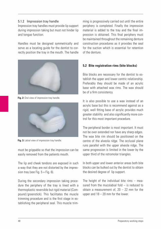
5.1.2 Impression tray handleImpression tray handles must provide lip support during impression taking but must not hinder lip and tongue function.
Handles must be designed symmetrically and serve as a locating guide for the dentist to cor-rectly position the tray in the mouth. The handle
ming is progressively carried out until the entire periphery is completed. Finally the impression material is added to the tray and the final im-pression is obtained. This final periphery must be maintained throughout the remaining denture construction procedures as it provides the seal for the suction which is essential for retention of the denture.
5.2 Bite registration rims (bite blocks)
Bite blocks are necessary for the dentist to es-tablish the upper and lower centric relationship. Preferably they should be made of an acrylic base with attached wax rims. The wax should be of a firm consistency.
It is also possible to use a wax instead of an acrylic base but this is recommend against as a rigid, well fitting base of acrylic provides much greater stability and also significantly more con-trol for this most important procedure.
The peripheral border is most important. It must not be over extended nor have any sharp edges.The wax bite rim should be positioned on the centre of the alveola ridge. The occlusal plane runs parallel with the upper alveola ridge. The same progression is limited in the lower by the upper third of the retromolar triangles.
In both upper and lower anterior areas both bite blocks can be bulked out by the dentist to obtain the desired degree of lip support.
The height of the individual bite rims – mea-sured from the mucolabial fold – is reduced to obtain a measurement of, 20 – 22 mm for the upper and 18 – 20 mm for the lower.
must be grippable so that the impression can be easily removed from the patients mouth.
The lip and cheek tendons are exposed in such a way that they are not distorted by the impres-sion tray (see Fig. 5 + Fig. 6).
During the secondary impression taking proce-dure the periphery of the tray is lined with a thermoplastic reversible but rigid material (Com-pound/greenstick). This facilitates the muscle trimming procedure and is the first stage in es-tablishing the peripheral seal. This muscle trim-
Fig. 2: Oral view of impression tray handle.
Fig. 3: Labial view of impression tray handle.
Preparatory working steps
49
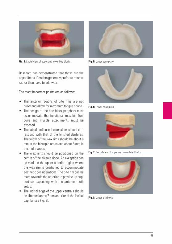
Research has demonstrated that these are the upper limits. Dentists generally prefer to remove rather than have to add wax.
The most important points are as follows:
• The anterior regions of bite rims are not bulky and allow for maximum tongue space.
• The design of the bite block periphery must accommodate the functional muscles Ten-dons and muscle attachments must be exposed.
• The labial and buccal extensions should cor-respond with that of the finished dentures. The width of the wax rims should be about 6 mm in the bicuspid areas and about 8 mm in the molar areas.
• The wax rims should be positioned on the centre of the alveola ridge. An exception can be made in the upper anterior region where the wax rim is positioned to accommodate aesthetic considerations. The bite rim can be more towards the anterior to provide lip sup-port corresponding with the anterior tooth setup.
• The incisal edge of the upper centrals should be situated aprox 7 mm anterior of the incisal papilla (see Fig. 8).
Fig. 5: Upper base plate.Fig. 4: Labial view of upper and lower bite blocks.
Fig. 6: Lower base plate.
Fig. 7: Buccal view of upper and lower bite blocks.
Fig. 8: Upper bite block.

50
• The height of the upper wax rim should be approx 20 – 22 mm measured from the mu-colabial fold in the area of the lip tendon, to the upper limit of the wax rim.
• The height of the lower wax rim should be approx 18 mm measured from the mucola-bial fold, in the area of the lip tendon, to the upper limit of the wax rim. The distal height of the upper and lower can be adjusted by softening of the bite rim with a rim former.
• The distal height should correspond with the upper third of the retromolar triangle.
• The flattened wax surface of the upper and lower bite rims should fit neatly together.
• The total height of the bite blocks should not exceed 40 mm.
Final countouring of the bite rims is usually car-ried out by the dentist in the patients mouth.
The dentist aligns the occlusal plane to the pupil line and Camper‘s plane using the bite fork. He also builds up the buccal area with wax until optimum cheek contact is reached.
All such information is required by the dental technician and can be recorded by means of a plaster or silicone key. This enables continuous checking during the setup as to whether cheek contact according to the wax bite record is cor-rect or otherwise.
Dentist markings on the bite registration block.
Midline, middle of faceThis line is not necessarily identical to the up-per and lower lip tendons or the midline of the model.
Canine lineThis determines the width of the upper anteri-ors, also where the tips of the canines are to be positioned. Also, their positioning can be deter-mined on the basis of the corners of the mouth or a vertical extension of the outer nasal wings.
Smile lineThis is decisive for the length of the upper ante-riors. The tooth necks should normally be above this line.
Occlusal planeIt follows the upper edge of the lower wax bite rim, i.e.: between the lower incisal edges in the anterior area and the distobuccal cusps of the lower second molar. It intersects the midline which is the fix point for the incisal pin, and runs parallel with Camper`s plane.
Fig. 9: Lower base plate with wax bite rim.
Preparatory working steps

51
5.3 Model fabrication
For full denture secondary models we use a class 1V hard stone. In a case with severe un-dercuts in the alveola ridge, a class 111 hard stone can be used. Regardless, it is essential that the functional periphery area of the models remain intact.
The functional periphery area shows:
In the upper:• The mucolabial fold• The alveolar ridge with the areas of the
maxillary tuberosities and palate• The transition from hard to soft palate and
(post dam area)• The lip and cheek tendons
Lower:• The alveolar ridge with the areas of the retro-
molar triangle• The mucolabial fold and sublingual areas• The muscle and tendon insertions of the
tongue and cheek musculature• The lip and cheek tendons
When manufacturing the functional models, it is essential to ensure that the functional margins remain completely intact. This is because the functional margins form the valve borders (mar-ginal seal) of the area in which a suction effect between the denture basis and the oral mucosa is created.
Fig. 12: Lower stone model.
For this purpose we attach a strip of adhesive wax to protect the peripheral area.
In order to maintain the stone’s physical proper-ties, it must be mixed under vacuum in the pre-scribed water powder ratio. The pouring of the model must be bubble free.
Fig. 11: Upper stone model.
Fig. 10: Dentist’s markings on the models and bite rims.
Smile line
Occlusal plane
Canine line
Midline

52 Preparatory working steps
5.4 Mounting of models in the articulator
Correct determination of the centric relationship of the upper and lower arch is essential for the functional success of complete dentures.
It is the method for the three dimensional deter-mination of the positional relationship of upper and lower arches. It is achieved by means of the bite blocks and the resulting bite records.
For this purpose, the condylar joints should be in their cranial and not their laterally shifted posi-tions in the articulator fossae.
A distinction is made between:
1. The relationship of the lower to the up- per (maxillomandibular relationship)
This refers to the definition of the transver-sal and sagittal relationship.
The vertical dimension (occlusal height) is generally 2 – 5 mm less than the interocclu-sal distance between the upper and lower. The transversal and sagittal relationship is determined with the aid of a gothic arch or by manual bite taking.
2. Position with reference to a cranial plane
Correct determination of the upper and lower arch relationship is essential for the mounting of the models on the articulator with reference to a cranial plane. The cra- nial orientation of both upper and lower models is transferred to the articulator by means of a face bow. If a face bow reading has not been taken, an elastic band can be used to represent the Camper’s line and Bonwill triangle for the purpose of moun- ting of the models. For this purpose the den-
tist must first intraorally align the wax bite rims to the Camper’s line.
5.5 The vertical dimension
The vertical dimension is determined chairside by the dentist. Any modification to this dimen-sion can have significant consequences. If in any doubt however, it is preferable to reduce the ver-tical dimension rather than increase it.
The vertical dimension naturally has a great in-fluence on the function and the Freeway Space of the prostheses.
A patient with Angle Class 2/Division II occlu-sion will certainly require more Freeway Space than a patient with Angle Class 1. In figures, the approximate values for the speaking distance (e.g. for the pronunciation of „s“ sounds) is as follows:
Overbite: 2 – 3 mmEdge-to-edge bite: 1 mmCover-bite: 4 mm

53
Notes

54
Notes
Preparatory working steps

55
6
VITA shade, VITA made.
Anatomy
Anatomical terms of location (directional terms)
The complete denture prosthesis accordingto qualitative criteria
Patients Dental / Medical History
Preparatory working steps
Articulators and articulation theories
Model analysis


57
In order to produce complete dentures, it is necessary to have a device which simulates the opening and closing movements of the mouth, the lateral and protrusion movements as well as the retrusion movements. A device which carries out such movements is described as a chewing simulator or an articulator.
6.1 Classification of articulators according to their design
6.1.1 Arcon articulatorsAn arcon articulator is a mechanical device which imitates the natural temporomandibular joint.
The condylar casings are situated – similarly to the TMJ – on the upper part of the articulator, and the condyles are attached firmly to the low-er part of the articulator. The advantage of this type of articulator is the unidirectional move-ment, as with natural chewing apparatus.
Examples: Denar, Mark II, New Simplex, Pana-dent, Protar, Quick-Perfekt, SAM, Stuart etc.
6.1.2 Non-arcon articulatorsIn contrast to the arcon articulator, the condy-lar casings are situated on the lower part of the articulator and the condyles on the upper part. All movement sequences are made in the oppo-site direction to the natural temporomandibular joint.
Examples: Atomic, Atraumatik, Candulor Articu-lator, Dentatus, Condylator, Mastikator, Rational.
6.2 Classification of articulators according to the type of movement that can be made
6.2.1 Average value articulatorsThese articulators correspond to Bonwill‘s tri-angle, and the inclination of the condylar path is taken to be a fixed value. Masticatory move-ments can therefore only be carried out on an average value basis.
Average value inclination of condylar path: 34°Average value Bennett angle: 15°
6.2.2 Semi-adjustable articulatorsThese allow different values to be set such as the inclination of the condylar path, the Bennett angle and in some articulators, the intercondylar distance.
6.2.3 Fully adjustable articulatorsThese articulators reproduce individual values obtained using an extraoral or an intraoral regis-tration procedure.
The aim of articulation theory is to interpret the existing anatomical conditions of the edentulous patient with the physical and mechanical condi-tions of the dynamic chewing system in such a way that feasible solutions for the practical fab-rication of complete dentures can be developed.
Literature on the subject offers various ex-amples with explanation‘s as well as practical working instructions.
6 Articulators and articulation theories

58
6.3 The various movements of the mandible are defined as follows
6.3.1 ProtrusionSymmetrical anterior movement of the lower jaw out of the position of maximum intercus-pation towards anterior.
6.3.2 Laterotrusion (working movement)The mandible moves sideways (laterally) out of the position of maximum intercuspation.
6.3.3 Laterotrusion side (working side)Moves away from the centre during lateral movements.
6.3.4 Mediotrusion (balancing movement)The mandible moves out of the position of maxi-mum intercuspation towards the centre.
6.3.5 Mediotrusion side (balancing side)The side of the mandible which is moved to-wards the centre during lateral movements.
6.3.6 RetrusionThe mandible is moved backwards and down-wards (posteriorly and down) out of maximum intercuspation.
6.3.7 RetractionMovement of the mandible out of the protru-sion position back into maximum intercuspation.
6.3.8 Laterotraction (lateral retraction)Movement of the mandible out of laterotrusion into maximum intercuspation.
6.3.9 Bennett angleThe Bennett angle is formed by the condylar path of the mediotrusion side (Fig. 1, from M1 to M2) and a line parallel to the median plane during lateral movement. It varies between 10° and 20°. Average value 15°.
6.3.9.1 Bennett movementThe lateral and spatial shifting of the laterotru-sion condyle in an outward direction. During lat-eral movement: Fig. 1, from L1 to L2.
The mediotrusion condyle accordingly moves more towards the centre. The lateral movement of the working condyle normally varies between 0.6 mm and 1.5 mm (Lundeen et al. 1978, Wirth 1996).
Diagrams show that the working condyle is not only moved in the lateral direction; its move-ment can also include a superiorly, inferiorly, anteriorly or posteriorly directed component.
The condyle can here carry out movements in the following directions:
superior = sideways (laterally) and upwards (laterosurtrusion)inferior = sideways (laterally) and downwards (laterodetrusion)anterior = sideways (laterally) and forwards (lateroprotrusion)posterior = sideways (laterally) and backwards (lateroretrusion).
In the absence of further information from the dentist, the average value for dentulous patients is taken to be 15° and for edentulous patients 20°.
The size of the movement has an influence on the Bennett angle.
Articulators and articulation theories

59
α L1 L2
M1M2
6.4 The Bonwill triangle
The Bonwill triangle is represented by an equi-lateral triangle that runs from the mandibular central incisal point to the centre of the right and left condyles (Fig. 2).
Mounting the models in the articulatorPreparation: Locating grooves are made in the base of maxillary and mandibular models with a plaster cutter, so they can be remounted after the dentures are completed. There are many dif-ferent systems which available for this purpose.
The ideal is to use a Split Cast, which enables even the most minor deviations to be recognised after completion of the denture, and to rectify or correct these accordingly.
If a face bow is not used for mounting, the model pairs can be placed according to average values in the Bonwill triangle.
This requires an elastic band and an incisal pin (Fig. 4).
Fig. 1
The intercondylar distance is consequently equal to the distance from the condyle to the centre of the lower central incisors (incisal point). The length of one side of the triangle is approximately 10.5 cm (Fig. 3).
Fig. 2
Fig. 3: Boundary of the Bonwill triangle.
Fig. 4: An elastic band is used to form the boundary of the
Bonwill triangle. This corresponds to the occlusal plane.

60 Articulators and articulation theories
Notes

61
7
VITA shade, VITA made.
Anatomy
Anatomical terms of location (directional terms)
The complete denture prosthesis accordingto qualitative criteria
Patients Dental / Medical History
Preparatory working steps
Articulators and articulation theories
Model analysis


63
4
12
6
7
3
5
1
3
5
4
2
6
The purpose of model analysis is to assess the prosthetic situation.
No human being is symmetrical. This means that the goal cannot be to achieve maximum sym-metry in the model analysis markings. Instead, each side must be assessed independently of the other and marked or characterised by means of the lines sketched on the model. These lines serve as a guideline for the subsequent wax set-up of the denture teeth.
From the point of view of statics however, func-tional stability is not automatically guaranteed in the resulting setup. These lines represent a guideline. Every complete denture must be checked intraorally for chewing stability by the dentist.
The dentist‘s markings on the model show• the centre of the alveolar ridge, transferred
to the margin of the model with the aid of a set square,
• the progression of the alveolar ridge with the aid of a pair of compasses on the model base,
• the retromolar triangle on the mandibular model.
Fig. 1: Upper jaw
1. Incisal papilla (papilla incisiva)
2. Large palatal ridge
3. Centre of alveolar ridge
4. Midline of model
5. Maxillary cusp (tuber maxillaris)
6. Palatal vibrating line
7. Canine point
Fig. 2: Lower jaw
1. Retromolar triangle (trigonum retromolare)
2. Centre of alveolar ridge, front
3. Centre of alveolar ridge, lateral
4. Midline of model
5. Border line (setup limit) for the distal sides of the last molars
The deepest point in the posterior area is also marked
on the model base.
If the height of the occlusal plane is not given, this can be calculated as an average value by measuring the distance between the deepest point of the mucolabial fold in the upper and lower jaw, and halving this value.
The final setup line is determined by determin-ing the alveolar ridge markings and transferring these to the outer margin of the model at the front and back. These form the outer limit of the static field.
Furthermore, the following values which the dentist indicated on the bite template are trans-ferred to the models: midline, canine line.
7 Model analysis

64
1
2
3
4
5
Fig. 3:
1. Centre of alveolar ridge of upper jaw
2. Interalveolar line (alveolar ridge connecting line)
3. Occlusal plane
4. Maximum innermost setup limit for lower teeth
5. Centre of alveolar ridge of the upper
Fig. 4:
Border line (setup limit) for the distal sides of the last molars
Deepest point = Position of the largest chewing unit, (i.e. pair of molar antagonists).
Behind the border line for the distal sides of the last molars begins the steep upward slope of the mandibular ramus. No more teeth should be set- up here, as this would result in the prosthesis slipping forwards (proglissement). Constant for-ward sliding of the mandibular prosthesis would result in age-related mandibular protrusion. In the case of flat alveolar ridges, the setup of the teeth ends at the mesial of the retromolar triangle.
If the inclination of the interalveolar line to the horizontal plane (4) is over 80°, a neutral bite should be setup; if it is under 80°, a cross-bite should be setup (Gysi).
Model analysis

65
Notes

66 Model analysis
Notes

67
8
VITA shade, VITA made.
Tooth selection
Functional stability
Anterior teeth
Aesthetics
Setup and function
Facts on the denture base
Denture finishing


69
4
12
6
7
3
5
8.1 Tooth selection based on patient‘s offspring
Tooth selection based on the teeth of the pa-tient‘s descendants or children has often proven helpful. If, for example, a female patient comes to the practice with her daughter, or a male pa-
tient with his son who has his /her own natural teeth, this is an excellent opportunity to deter-mine the tooth shape for the parent. Patients often comment on the fact that their teeth used to look just like this or that.
Fig.1: Mother and daughter. Fig. 2: Father and son.
8 Tooth selection

70
Fig. 4
8.2 Selection of anterior teeth width according to Lee
When selecting teeth according to Lee, the dis-tance between the nasal wings is measured. This generally corresponds to the distance from the midline of one canine to the midline of the other canine.
8.3 Selection of anterior tooth positioning according to Gerber
The contour of the nasal base line serves as a guideline.
Fig. 3: Definition according to Lee.
Fig. 5
Fig. 6
Tooth selection

71
8.4 Selection of anterior tooth moulds according to Gysi
The tooth shape results in facial harmony.
8.5 Tooth selection according to physiognomy (Williams)
For many dental practitioners, the selection of the tooth mould according to Williams is an estab-lished method for determining the tooth mould corresponding to the shape of the patient‘s face or type. In addition to this, the classification ac-
cording to the four different types of facial shape is more or less an international standard. This classification, however – and likewise the clas-sification according to Kretchsmer – originates more from the early days of dental prosthetics.
Fig. 7
Fig. 8
Fig. 9
Fig. 10
Fig. 11
Fig. 12

72
8.6 Tooth selection according to constitution types (Kretschmer)
The three constitutional types – athletic, lepto-some and pyknic – form the basis for tooth se-lection according to Kretschmer.
Fig.13: Pyknic type – oval tooth shape.
Fig.14: Leptosome type – triangular tooth shape.
Fig.15: Athletic type – angular, almost square tooth shape.
Tooth selection

73
8.7 Tooth selection according to the anatomical model
When no tooth selection information is available from the dentist, the maxillary alveolar ridge can also be taken as a basis for selecting the ante-rior tooth shape.
Fig. 16
Oval alveolar ridge Pointed alveolar ridge Square alveolar ridge
oval anterior tooth shape triangular tooth shape square anterior tooth shape

74
Notes
Tooth selection

75
9
VITA shade, VITA made.
Tooth selection
Functional stability
Anterior teeth
Aesthetics
Setup and function
Facts on the denture base
Denture finishing


77
Fig. 1: Vectors of force meet the alveolar ridge at right
angles.
9.1 When can a denture be said to be stable?
When functional forces are applied to the den-ture in the mouth and the denture remains un-moved by tilting or displacement it can be said to be stable, i.e.: positionally stable under mas-ticatory forces.
9.2 What happens with an unstable denture?An incorrectly designed denture will be unstable when:
• The denture teeth are incorrectly positioned. Due care has not been taken in regard to THE EXTENT OF THE DENTURE BASE the extent of its borders and design of its periphery.
The functional requirements of providing suffi-cient clearance for lip and muscle tendons are deficient.
Such shortcomings lead to “lifting” and dis-placement of the denture from the alveola ridge during speech or other functions. They will also cause the development of pressure spots on the mucosa.
9.3 Vectors of force – what are they?
The multidirectional forces which act on func-tioning denture and teeth are referred to as vec-tors of force.
A vector of force represents the characteristics of a force. In Fig. 1, forces are indicated by ar-rows which also indicates a range of forces which may be in action during masticatory func-tion. In order to overcome such problems it is necessary to understand what occurs when a denture tooth is ground in the pursuit of elimat-
ing such a problem and what consequences may follow.
9.4 The interplay of forces
In order not to be helpless in overcoming these forces the following should be kept in mind.All vectors of force acting on a denture should cancel each other out, i.e.: the sum of all vectors of force acting on a denture should be zero.I as far as possible all vectors of force must meet the alveola ridge at right angles.
In this way the various forces acting on the mandibular denture help to centre the denture squarely on the alveola ridge.
9 Functional stability

78 Statics and chewing stability
In this way the denture is prevented from being pushed down and forward on a sloping plane.
If the setup ends at the distal of the first molar, the remaining gap is built up in denture base acrylic towards the retromolar pad. It is definite-ly out of occlusion and slopes away lingually and buccally towards the periphery of the denture. This configuration prevents food accumulation.
It is for this reason that the second molar is sometimes omitted from a setup as it would oth-erwise have to be positioned on the steep slope of the mandibular ramus. This would be contrary to the vectors of force principles described and not in harmony with the alveola ridge. If set, the second molar would cause functional displace-ment of the denture.
Fig. 2: Incorrect positioning of the second molar.
Fig. 3: Proglissement caused by the force acting on the
denture.

79
Notes

80 Statics and chewing stability
Notes

81
9
VITA shade, VITA made.
10
Tooth selection
Functional stability
Anterior teeth
Aesthetics
Setup and function
Facts on the denture base
Denture finishing


83
7mm
10 Anterior teeth
• The length of the upper anteriors corre-sponds to the distance between the lip clo-sure line and the smile line.
• The line connecting the tips of both upper canines runs through the centre of the incisal Papilla (CPC line).
10.1.1 Tooth length The incisal edge of the maxillary central inci-sors should be aprox., 0.5 – 1.00 mm longer than the lower edge of the upper lip, when the upper lip is passive (for men, 1.0 mm longer and for women, 2.0 mm longer).
These values concerning anterior tooth length are approximate and serve as a starting point. If followed, they will often deliver satisfactory results.
10.1 Positioning of the anterior teeth
It can generally be assumed that in a normal oc-clusal situation the upper anteriors are situated at a distance of about 7 mm anteriorally of the incisal papilla (Fig. 1).
With a close bite the distance is about 6 mm and a protrusive bite about 9 mm.
The anterior teeth are positioned according to anatomical, functional, aesthetic, and phonetic requirements.
The following points should be heeded:
• The denture teeth should be incorporated in the wax rim in such a way that they continue the contour of the wax rim.
• Both mesial interdental surfaces of the upper central incisors and the mesial interdental surfaces of the lower central incisors should correspond to the midline markings on the model (Refer to diagram in section 5.2.)
• The midlines of the upper canines correspond to the position of the canine line markings on the model ( Refer to diagram in section 5.2.)
Fig. 1 Fig. 2: CPC line (canine, papilla, canine).

84 Anterior teeth
• The incisal edge of each lower lateral inci-sor runs approximately parallel with the oc-clusal plane.
• The tips of both canines are positioned slightly above the occlusal plane.
The labial surfaces of the upper anteriors sup-port the upper and lower lips (Fig. 4).
A standard positioning of the upper anteriors is achieved as follows (Fig. 5 / labial view).• The central incisors are straight and upright.• The lateral incisors are inclined cervically
and slightly laterally.• The canines are more upright with the neck
slightly towards the labial.
• The central incisors and canines are parallel to the pupil line and correspond to the posi-tive smile line in the arch.
10.2 Setting the anterior teeth.
10.2.1 Standard setup methodsThe anterior teeth, as explained following, can be set according to a standardised method. This is intended only as a guideline which can and should be modified to suit the individual patient case.
Upper• The incisal edge of both upper central inci-
sors are situated +/- 1 mm above the occlu-sal plane.
• The incisal edge of each lateral incisors is situated +/- 0.5 mm above the occlusal plane.
• The incisal edged of each incisor runs ap-proximately parallel with the occlusal plane.
• The tips of both canines are positioned ap-proximately at the level of the occlusal plane.
• The tips of both canines are situated at an approximate distance of 10 mm from the end of the first pair of palatal ridges (Fig. 3).
Lower• The incisal edge of each lower central incisor
corresponds precisely to the contour of the occlusal plane.
Fig. 3
Fig. 4
approx. 10 mm
Fig. 5
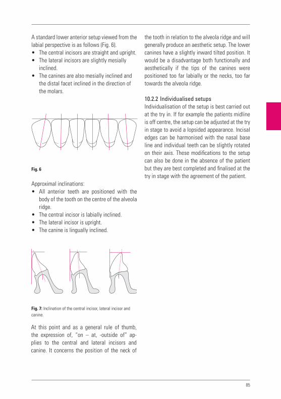
85
the tooth in relation to the alveola ridge and will generally produce an aesthetic setup. The lower canines have a slightly inward tilted position. It would be a disadvantage both functionally and aesthetically if the tips of the canines were positioned too far labially or the necks, too far towards the alveola ridge.
10.2.2 Individualised setupsIndividualisation of the setup is best carried out at the try in. If for example the patients midline is off centre, the setup can be adjusted at the try in stage to avoid a lopsided appearance. Incisal edges can be harmonised with the nasal base line and individual teeth can be slightly rotated on their axis. These modifications to the setup can also be done in the absence of the patient but they are best completed and finalised at the try in stage with the agreement of the patient.
A standard lower anterior setup viewed from the labial perspective is as follows (Fig. 6).• The central incisors are straight and upright.• The lateral incisors are slightly mesially
inclined.• The canines are also mesially inclined and
the distal facet inclined in the direction of the molars.
Approximal inclinations:• All anterior teeth are positioned with the
body of the tooth on the centre of the alveola ridge.
• The central incisor is labially inclined.• The lateral incisor is upright.• The canine is lingually inclined.
At this point and as a general rule of thumb, the expression of, “on – at, -outside of” ap-plies to the central and lateral incisors and canine. It concerns the position of the neck of
Fig. 6
Fig. 7: Inclination of the central incisor, lateral incisor and
canine.

86
Fig. 8.1: VITA MFT T46 – the teeth are rotated slightly around
their vertical axes, a labial view.
Fig. 8.2: ... and from an incisal viewpoint.
Fig. 9.1: VITA MFT S47 – the pronounced anterior positioning
of the central incisors. The labial view ...
Fig. 9.2: ... and the incisal view shows this very nicely – note
the slightly retruded lateral incisors.
Anterior teeth
Examples of individual anterior setups

87
Fig.10.1: VITA MFT T46 – typical for class II/2, pronounced
incisal retrusion.
Fig.10.2: The incisal view is a good example – the butterfly
position of the central incisors in combination with the
typical positioning of the lateral incisors.
Fig.11.1: VITA MFT R42 – not too conspicuous in the labial
view ...
Fig.11.2: ... the slightly retruded central incisors and more
conspicuously protruding lateral incisors.

88 Anterior teeth
Fig.12.1: VITA MFT L37 – individual anterior positioning in
the lower is a good aesthetic solution ...
Fig.12.2: ... most clearly visible in the „broken arch“ form.
Setups of this type are refined with correspondingly abraded
facets caused by protrusive movements.
Fig.13.1: VITA MFT L34 – Example of a moderately individu-
alised setup.
Fig.13.2: A rather even contour despite slight tooth rotation
around the vertical axis.

89
In this respect, nature itself shows the way. In nature, we can observe how the oral cavity is divided into sections in order to ensure faultless phonetics.
We also recognize the interconnection of denti-tion with speech and phonetic function. These develop during growth of the primary dentition and continue during development of the perma-nent dentition.
Once this speech / phonetic function has been learned during development, it is stored in the brain and will remain for life.
If the denture teeth are wrongly positioned, the patient will likely be able to reach only an approximation of their original speech pattern. However, every complete denture wearer devel-ops phonetic tricks in order to overcome short-comings and speak reasonably well.
If by comparison with the previously described example, the teeth are correctly positioned, the patient; even after wearing a denture with poor phonetics for 20 years, will regain phonetic func-tion and revert to their original speech pattern.
How can this be achieved and how to correctly position the teeth in the first place?It is necessary to explore the patient’s, “stored phonetic speech pattern” and set the teeth pho-netically (so to speak).
10.2.3 Overbite – overjet Overbite – sagittal (horizontal) overbiteAn overbite is a vertical anterior overbite. This can have a dimension of up to 2 mm aprox. The term overbite, refers to the sagittal anterior overbite, horizontally of up to 2 mm aprox. As a general rule it is assumed that “overbite equals overjet” (Fig. 14).
This usually has a dimension of 1 mm which means that the overbite and overjet should cor-respond precisely if balancing of the mandibular movements is intended.
10.3 Phonetics
10.3.1 Problems and the appropriate solutions
To enable a complete denture patient to speak properly, consideration should be given to set-ting up in phonetic balance.
In order to be able to begin with the restoration of lost dentition, it is necessary to be aware of the function of the various oral segments (i.e.: tongue, palate, lips, etc. and their respective functions).
Fig. 14
Overjet
Overbite
Recouvrement
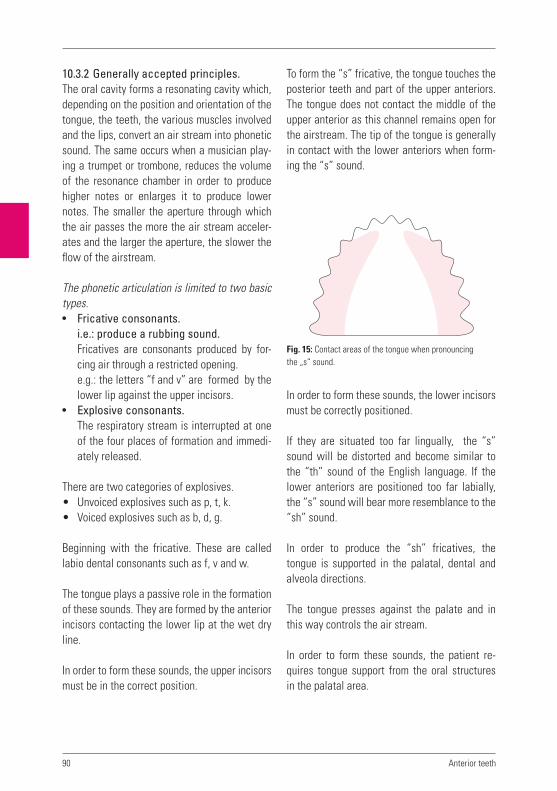
90
To form the “s” fricative, the tongue touches the posterior teeth and part of the upper anteriors. The tongue does not contact the middle of the upper anterior as this channel remains open for the airstream. The tip of the tongue is generally in contact with the lower anteriors when form-ing the “s” sound.
In order to form these sounds, the lower incisors must be correctly positioned.
If they are situated too far lingually, the “s” sound will be distorted and become similar to the “th” sound of the English language. If the lower anteriors are positioned too far labially, the “s” sound will bear more resemblance to the “sh” sound.
In order to produce the “sh” fricatives, the tongue is supported in the palatal, dental and alveola directions.
The tongue presses against the palate and in this way controls the air stream.
In order to form these sounds, the patient re-quires tongue support from the oral structures in the palatal area.
10.3.2 Generally accepted principles.The oral cavity forms a resonating cavity which, depending on the position and orientation of the tongue, the teeth, the various muscles involved and the lips, convert an air stream into phonetic sound. The same occurs when a musician play-ing a trumpet or trombone, reduces the volume of the resonance chamber in order to produce higher notes or enlarges it to produce lower notes. The smaller the aperture through which the air passes the more the air stream acceler-ates and the larger the aperture, the slower the flow of the airstream.
The phonetic articulation is limited to two basic types.• Fricative consonants.
i.e.: produce a rubbing sound.Fricatives are consonants produced by for-cing air through a restricted opening.e.g.: the letters “f and v” are formed by the lower lip against the upper incisors.
• Explosive consonants.The respiratory stream is interrupted at one of the four places of formation and immedi-ately released.
There are two categories of explosives.• Unvoiced explosives such as p, t, k.• Voiced explosives such as b, d, g.
Beginning with the fricative. These are called labio dental consonants such as f, v and w.
The tongue plays a passive role in the formation of these sounds. They are formed by the anterior incisors contacting the lower lip at the wet dry line.
In order to form these sounds, the upper incisors must be in the correct position.
Anterior teeth
Fig. 15: Contact areas of the tongue when pronouncing
the „s“ sound.

91
• The chin moves slightly downwards when b is pronounced.
• The chin shows a sudden downwards move-ment when p is formed.
What we cannot see• The teeth have only a slight inter-occlusal
separation (freeway space).• The tip of the tongue lies on the lower inci-
sors.• The underside of the tongue lies flat as dur-
ing the formation of the „a“ sound.
Classification according to placeof articulation:• Labial (Latin: labium = lip)
p, b, m, f, v, ph, w, pf The lips form a more rounded-elongated aperture.
• Dental (Latin: dens = tooth): sh, t, d, tz, s, z, n The upper incisors articulate against the inner edge of the lower lip. The tip of the tongue articulates against the inner edge of the upper incisors.
• Palatal (Latin: palatum = palate) n, l, „ch“ as in „chew“ The Palatal consonants result when the tip of the tongue articulates against the anterior palate.
• Velar (Latin: velum = sail): k, g, ng, nk, q, ch, j, or ch as in the Scottish pronounciation of “loch. The place of articulation is between the posterior portion of the tongue and the soft palate.
Failing this, the patient can only improvise these sounds with difficulty by shifting the location of articulation posteriorally. The result will then be an approximation, similar to the Scottish pro-nounciation of the word, “loch.”
Explosive consonants p, t, k, b, d, g are formed when the air stream is sealed off ante-riorally by the tongue, lips, or other parts of the mouth and then rapidly released.
The correct positioning of the upper incisors is essential for the formation of the consonants t and d and in the case of consonants k and g, the positioning of the posteriors and corresponding palatal support is important. Consonants b and p are formed purely labially.
Description of facial/oral positions and mo-vements in formation of consonants m, b and p.
What can we see?• When pronouncing “m”, complete lip
closure can be observed. • In the case of b, the lips are released slightly.• With P, the lips move apart rapidly and the
cheeks swell slightly.• The chin does not move when m, is pro-
nounced.
Fig. 16: Contact areas of the tongue when pronouncing
the „sh“ sound.

92
Notes
Anterior teeth

93
9
VITA shade, VITA made.
11
Tooth selection
Functional stability
Anterior teeth
Aesthetics
Setup and function
Facts on the denture base
Denture finishing


95
To this purpose, it is essential to look closely and observe the effects evident in different surfaces. For example the texture of a surface such as gingival tissue or that of a tooth which causes reflected light to diffuse under varying lighting conditions.
Of course shape, value and colour are also im-portant.
A crown which differs very slightly in colour from the ideal but which has excellent shape, texture and value will be significantly less of a disturbance to the oral harmony of the patient than a shade perfect crown that has an inappro-priate shape and texture or value.
Regarding complete dentures, not only tooth form and positioning are important aesthetically, but the gingiva also must appear as a reproduc-tion of the natural gingiva.
How do we define aesthetics? Aesthetics are often associated with beauty.
“Beauty is in the eye of the beholder.”
The word, aesthetic, can also be described as being “pleasing to the eye“, an impression is perceived by the eye and conveyed to the brain.
A varying play of light colour and form can give varying emphasis to a motif and highlight cer-tain details.
Aesthetics in nature does not mean symmetry and regularity, but a harmonious mix of irregu-larity and asymmetry.
When speaking of aesthetics it is inappropriate to speak of aesthetics being correct or incorrect as aesthetic concepts are very flexible. General-ly a dental restoration can be described as hav-ing a natural appearance or is close to natural. If for example we produce a dental restoration or a crown which closely resembles the natural, we say it has an aesthetic appearance.
11 Aesthetics

96
Notes
Aesthetics

97
9
VITA shade, VITA made.
12
Tooth selection
Functional stability
Anterior teeth
Aesthetics
Setup and function
Facts on the denture base
Denture finishing


99
The buccal cusps are out of contact. The lower posteriors are setup according to the alveolar ridge and curve of spee in order to obtain den-ture stability. Their occlusal surfaces appear horizontally aligned from a labial perspective.
The upper and lower posteriors are brought into contact in such a way that they articulate ana-tomically and functionally. Note: there is always a free space left between the upper and lower buccal cusps.
VITA MFT teeth are generally setup in a tooth to tooth relationship. Should it be necessary for some reason to set the teeth in a tooth - to – two – teeth relationship this is quite acceptable.
Advantages of lingualised occlusion.The aim of lingualised occlusion is to stabilise the dentures while providing maximum space for the tongue.
The occlusal forces transferred to the oral mu-cosa and the underlying bone substance are thereby minimised.
This generally reduces the strain on the denture bearing area and can be an essential ingredient in the survival of implant cases.
12.1 Setup concepts
Generally accepted principles.When setting up posterior teeth stability of the denture is a major goal applicable to all denture prosthetics. This should be kept in mind when addressing and overcoming the range of clinical difficulties encountered daily in denture con-struction.
Regardless of which concept is to be used, cor-rectly determined centric relation is an essential and fundamental base from which to begin the work. The only possible exception may be when using teeth with zero degree cusps.
It makes no sense to try to conform to a single theoretical concept at any price without be-ing aware of the practical consequences. This means that the suitability of a particular concept must be determined for each particular case.
Three concepts are described in the following and which can be utilized in virtually all cases.
12.1.1 Lingualised occlusion
VITA MFT®
The principle of lingualised setup.In lingualised occlusion the lingual working cusps of the upper posterior teeth occlude into the central fossae of the lower posteriors.
12 Setup and function

100 Setup and function
Fig. 1
Fig. 2
Fig. 3
the fossa of the first lower molar (Fig. 2). The distolingual cusps comes into contact with the distal marginal ridge of the first lower molar. The second upper premolar is then brought into con-tact with its antagonist. The palatal cusps of the latter should come into contact with the fossa of the second lower premolar (Fig. 3).
Procedure:1. Setup beginning with the first upper molarPlease note: with lingualised occlusion, the lower posteriors are setup vertically, i.e. are not lingually inclined (Fig. 1). The dominant mesio-lingual cusp of the first upper molar bites into

101
Fig. 4
Fig. 5
Fig. 6
The buccal cusps of all upper posteriors are situ-ated slightly higher than, and out of contact with the buccal portions of their antagonists (Fig. 6).
The palatal cusp of the first upper premolar should now bite into the fossa area of the first lower premolar (Fig. 4). Finally, the second upper molar is setup. The palatal cusps grip into the fossa area of the second lower molar (Fig. 5).

102 Setup and function
Fig. 7
Fig. 8
Fig. 9
fossa area of the first lower premolar (Fig. 8). The second upper premolar is then brought into contact with its antagonist. The lingual cusp of the latter should grip into the fossa of the sec-ond lower premolar only (Fig. 9).
2. Setup beginning with the first upper premolarPlease note that in lingualised occlusion, the lower posteriors are first setup horizontally, i.e. not lingually inclined (Fig. 7). The lingual cusp of the first upper premolar should now bite into the

103
Fig. 10
Fig. 11
Fig. 12
The lingual cusps bite into the fossa area of the second lower molar (Fig. 11). The buccal cusps of all upper posteriors are always situated slightly higher, and out of contact with the buccal por-tions of the antagonists (Fig. 12).
The dominant palatal cusp of the first upper mo-lar bites into the fossa of the first lower molar. The distolingual cusp meets the distal marginal ridge of the first lower molar (Fig. 10). Finally the second upper molar is setup.
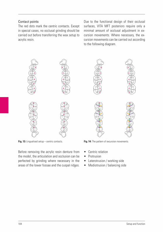
104 Setup and function
Fig. 13: Lingualised setup – centric contacts.
Contact pointsThe red dots mark the centric contacts. Except in special cases, no occlusal grinding should be carried out before transferring the wax setup to acrylic resin.
Before removing the acrylic resin denture from the model, the articulation and occlusion can be perfected by grinding where necessary in the areas of the lower fossae and the cuspal ridges.
Due to the functional design of their occlusal surfaces, VITA MFT posteriors require only a minimal amount of occlusal adjustment in ex-cursion movements. Where necessary, the ex-cursion movements can be carried out according to the following diagram.
• Centric relation• Protrusion• Laterotrusion / working side• Mediotrusion / balancing side
Fig. 14: The pattern of excursion movements.

105
12.1.2 Anterior-canine guidance with ABC contacts
Dr Karl Hiltebrandt, one of the founders of VITA in the early 1920’s, was somewhat of a visionary and some say, ahead of his time. Dr Hiltebrandt concluded that a “normal” bite is driven by neu-romuscular guidance rather than tooth guided movements as was thought to be the case at the time.
When constructing full dentures for edentulous patients the clinician is presented with a series of problems which must be overcome if stable, comfortable and functional dentures are to re-sult.
Two of the most common problems to overcome are divergent atrophy of both maxilla and man-dible and the fact that the lower denture sits partially on a sloping incline (see section 1.8 / bone / arch atrophy).
This situation is not as nature intended and the reason the patient is in need of a “replacement.” All the various forces acting on the dentures, particularly those occurring during masticatory movements, must be balanced out against one another.
This does not mean grinding the occlusion in order to obtain excursion movements but, as it were, “entry lanes”, with corresponding canine guidance which culminate in group guidance. The dentures can therefore be returned to cen-tric position from every dislocated position sim-ply by clenching the teeth together.
Necessary posterior antagonist contacts to achieve occlusal stability. Contacts with the opposing teeth (antagonist contacts) are generally classified into three types of positional relationships:
„A“ contacts:Buccal cusps – upper and lower contacts. The shearing (non working) cusps of the upper teeth are in contact with the working cusps of the lower teeth (Fig. 15).
„B“ contacts:Lower buccal cusps contact with lingual cusps of the upper. The working cusps of upper and lower are in contact (Fig. 15).
„C“ contacts:Upper and lower lingual cusp contacts. The working cusps of the uppers and the shearing (non working) cusps of the lowers are in contact. As a rule,either A and B, or C and B contacts are sufficient. They provide stable occlusal and axial loading of the teeth.
A, B and C contacts can be present at the same time and this is fine. What is important is their uniform distribution.
Fig. 15
Upper
Lower
A
B
C

106 Setup and function
Fig. 17: Individual distribution of the ABC contacts.
In order to stabilise both the mandibular and the maxillary dentures, an A contact and a B con-tact, or a B contact and a C contact are required (see Fig. 16).
Fig. 16
A
Upper A
B
C
A
B
C
Lower
B
C

107
12.1.3 Setup according to generally accep- ted principles with buccal contacts
After the anterior teeth have been setup taking the sagittal overbite (overjet) into account as de-scribed in chapter 10.2, the posterior teeth can be set in position.
The following applies to the setup of all lo-wer posteriors:• They are generally positioned on the centre
of the alveolar ridge.• The central fissures should be in a straight line
which runs between the tips of the canines and the centre of the retromolar triangle.
• The buccal cusps are situated on the tangent of the Bonwill circle, which reaches from the buccal limit of the first premolar to the buccal limit of the retromolar triangle.
• The lingual cusp tips are situated on Pound‘s line.
• The posteriors lingually inclined => tooth inclination increasingly towards the distal. (axial inclination of tooth crown towards the lingual in relation to axial inclination of tooth root, a characteristic of mandibular teeth).
The following applies to setting of the upper posteriors:• If possible, they are positioned on the centre
of the alveolar ridge.• The central fissures are situated on an ellip-
tical connection line between the tips of the canines and the tubera maxillae.
• Viewed from in front, less and less of the buccal surface can be seen from the first pre-molar to the second molar; this gives rise to the „buccal corridor“.
• They are buccally inclined.• The first lower premolar is setup. The buccal
cusp tips touch the occlusal plane.
• The second premolar is set. It is situated ap-prox. 1 – 1.5 mm below the occlusal plane.
• The first lower molar must be setup in the area of the lowest point of the alveolar ridge. Taking into account the sagittal and transver-sal compensation curves.
• The buccal cusps tips are approx. 2 mm be-low the occlusal plane, rising towards the distal. If there is no danger of proglissement (lower denture forward displacement), the second lower molar can also be setup. Oth-erwise the sagittal progression of the curve in the area of the first molar should be com-pensated, i.e. distally raised.
• The first upper molar is brought into optimum intercuspation. Subsequently the second upper premolar and then the first upper pre-molar are inserted into the available space.
• If, as previously described, it is possible to set the second lower molar, the upper anta- gonists can then be added, and brought into intercuspation.
In the lower, the distobuccal cusps of the se-cond molars touch the occlusal plane. If space is limited, premolars can be substituted in-stead. What is important ultimately is that no more teeth are not beyond the setup limit, i.e. no teeth are setup into the steep upward slope of the mandibular ramus – otherwise there is a risk of proglissement (lower denture forward displacement)!
In order to achieve a balanced occlusion, pro-ceed as described in chapter 14.3.3.

108 Setup and function
Fig. 17: Mesal view of setup.
Fig. 18: Lingual view of setup.
Fig. 19: Mesal view of setup.
Fig. 20: Lingual view of setup.

109
Fig. 21: Buccal view of second upper premolar and first upper molar.
Fig. 22: Lingual view of first and second upper premolar and first molar ...
Fig. 23: ... and the buccal view.
Fig. 24: Lingual view of setup.

110 Setup and function
Fig. 26: Setup with buccal contacts according to generally
accepted principles.
Fig. 25: Buccal view of setup.

111
12.2 Important characteristics
12.2.1 Cheek contactWhat is the purpose of cheek contact, and why is it so important?
In order to have the patient feel that their den-tures are stable and comfortable it is necessary that the posterior teeth have contact with the cheeks.
It is also of key importance that the posteriors are positioned correctly on bone supported mu-cosa, preferably on the alveola ridge. (This is not always possible.) What remains important how-ever is, osseous support of the mucosa.
The dentist should build out the wax flanges, until cheek contact is achieved. This assists in stabilising the wax up to some degree by having cheek contact on both left and right sides. It also contributes to centric stability.
Additionally, during mastication, the food bolus is automatically maintained on the posterior occlusal table until it is ready to be conveyed further. Without cheek contact the denture is less stable and the food bolus will accumulate between the cheek and denture which subse-quently requires removal with the tongue or the finger.
The importance and function of cheek contact is commonly underestimated.
12.2.2 Different types of biteIn order to produce functionally stable dentures, the skeletal and dental parameters of each case must be considered. Such information must be accounted for in the planning and implementation of complete dentures.
For example, an unfavourable progression of bone atrophy makes it more difficult to produce a denture that is positionally stable under mas-ticatory pressure.
By selecting the appropriate type of bite, den-ture stability problems caused by difficult skel-etal conditions or unfavourable progression of bone atrophy can be overcome.
12.2.3 Normal biteWhenever possible teeth should be setup in a normal bite, but not at any price!
If unfavourable interalveolar conditions pres-ents, a cross bite or edge to edge bite is used, particularly in regard to partial dentures.

112
12.2.4 CrossbiteAs already described in section 7 on model analysis, when the inter – alveola connection line has an angle of less than 80 degrees, the teeth are set in a cross bite in order to avoid or minimise problems of instability.
To this purpose the maxillary buccal cusps (i.e.; the shearing non working cusps) become work-ing cusps which bite into the fossa of the lower posteriors. As a rule, the first premolar is set in neutral occlusion, then the second premolar is set in an edge to edge bite. (to this purpose the cusps must be ground) This is followed by the first or second molar which is set in a cross bite position.
12.2.5 Edge to edge biteAn edge to edge bite is normally not used in the posterior of a setup. An exception can be a “transitional tooth” such as a second premolar in a cross bite, which has been ground into an edge to edge bite relationship (refer section 12. 2. 3).
It is also possible to achieve an edge to edge bite with posteriors that have a flat occlusal ta-ble and without a definite centric position. This is not recommended however as the patient may experience a tendency towards “cheek biting“. In this circumstance a cross bite or a normal bite is usually possible.
Partial dentures can also present an exception to this but, depending on the particular situa-tion a suitable compromise can be found.
Edge to edge bite relationships are most com-monly found in the anterior region.
12.3 Vertical dimension / occlusal height
Determination of the vertical dimension is not a simple matter.
When the vertical dimension has not been deter-mined correctly the patient’s dentures may cause a clackety – clacking sound when speaking. This is usually more pronounced with ceramic teeth than with acrylic teeth. The ceramic however is not the cause of the sound but rather an in-correctly set vertical dimension. In years past, instead of correcting the vertical dimension the ceramic teeth were sometimes replaced with acrylic teeth. This resulted in a lower volume of the sound but did not eliminate the cause. It was commonly thought by the general public that “crockery teeth” as they were known were the cause of the problem!
On the other hand, if the vertical dimension is insufficient, the effect will be less pronounced but the aesthetics will be poor. It is essential the vertical dimension be correct.
Setup and function

113
Notes

114
Notes
Setup and function
115
9
VITA shade, VITA made.
13
Tooth selection
Funtional stability
Anterior teeth
Aesthetics
Setup and function
Facts on the denture base
Denture finishing


117
It can also be observed that this very thin gingi-val tissue is opaque and as a consequence, the underlying tooth neck / root is not visible.
It is for this reason we use and recommend opaque acrylic for dentures where we want the best possible aesthetic result. It is our opinion that transparent acrylics are aesthetically un-suitable for use as denture base material. A key area of gingival contouring is the design of the interdental papillae. The papillae should have the form of a droplet (see Fig. 1) and be oriented towards the approximal. The papillae always fin-ishes well short of the incisal edge and occlusal surface.
The simplest and best way to reproduce natu-rally appearing gingival is with pink sheet wax sheet and the use of wax carving instruments (Figs. 2 and 3).
13.1 Gingival contouring
How is natural gingival structured and how should it be reproduced? Natural gingival con-sists of marginal gingiva and gingival papillae.
There is no clear cut boundary between the marginal gingiva and the attached gingival but a gradual transition between the two. The mar-ginal gingival covers the osseous alveola pro-cess, is keratinised and has a pitted orange peel texture (surface stippling).
The mucogingival junction forms the transition between the attached gingival and the alveola mucosa. This is distinguishable and easily rec-ognised, as the gingival mucosa is darker and thinner than the attached gingival.
13.1.1 How can naturally appearing gingival be reproduced?An appropriate expression might be that “less is more“. Exaggerated carving and over contour-ing in the gingival margin area is painstakingly difficult to trim and also can be difficult for the patient to keep clean.
If we observe natural healthy gingiva, it can be observed that the transition from tooth to gingiva occurs at a very flat angle precisely in the vicinity of the gingival margin.
Fig. 3Fig. 1: Prosthesis ideally modelled in wax.
Fig. 2
13 Facts on the denture base
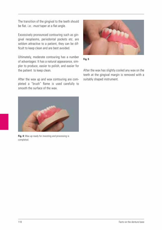
118
The transition of the gingival to the teeth should be flat. i.e.: must taper at a flat angle.
Excessively pronounced contouring such as gin-gival neoplasms, periodontal pockets etc. are seldom attractive to a patient, they can be dif-ficult to keep clean and are best avoided.
Ultimately, moderate contouring has a number of advantages: It has a natural appearance, sim-pler to produce, easier to polish, and easier for the patient to keep clean.
After the wax up and wax contouring are com-pleted a “brush” flame is used carefully to smooth the surface of the wax.
After the wax has slightly cooled any wax on the teeth at the gingival margin is removed with a suitably shaped instrument.
Facts on the denture base
Fig. 5
Fig. 4: Wax up ready for investing and processing is
completed.

119
After removing wax carving residue, the con-tours can be smoothed and rounded off using a soft and not so hot flame of an alcohol torch. A clean methodical way of working is essential.
Next the tooth / gingival transition is defined and any excess wax on the teeth removed (Fig. 9).
The edge created as a result of exposing the cervical area is bevelled, the angle as previously described should be flat.
These steps enable a good basic gingival struc-ture to be achieved by simple means.
Fig. 6
Fig. 9Fig. 7
Fig. 8: Smoothing the wax with alcohol flame.

120
An essential part of a good, naturally appearing gingival reproduction is the papillae.As can be seen in the above photograph, the tip of the papillae is removed and shortened using an arrow headed instrument (Fig. 10).
The dental technician next decides on the de-gree of wax contouring in order to obtain a natu-rally appearing gingiva (Fig. 11).
The remaining tip of the papillae and the small amount of wax carving are slightly rounded so that there are no angles and the wax gingiva appears to flow interdentally. Finally, the interdental gingiva can be smoothed very care-fully using a soft flame such as that of an alcohol torch (Care must be taken, not to apply the flame to the teeth).
In a situation where the patient has a big smile and shows a lot of gum when they laugh, thoughtful contouring of the lip tendon area can serve to enhance the natural appearance of the gingiva (Superior labial frenulum) (Fig. 13).
Facts on the denture base
Fig. 10 Fig. 12
Fig. 11 Fig. 13

121
13.3 Determining the borders of the denture.
13.3.1 How is the border / periphery of the denture determined.This is determined by the limits of the functional impression and is of key importance for the com-pleted dentures.
The thickness of the periphery must not be al-tered or randomly reduced, it should retain the exact dimensions determined by the dentist when taking the functional muscle trimmed im-pression. Only in this way can the outer periph-eral seal be obtained.
The periphery of the denture must reach both the attached and mobile mucosa circumferen-tially around the denture. Optimum adhesion requires the denture base to extend into the mo-bile mucosal areas which does not move during functional activity. Between the inner peripheral sea and the mobile mucosa there is an ‘inner’ seal. Between the outer edge of the functional border and the mobile mucosa which rests on top of this, there is an outer seal on the suction area.
With many dentures a frequent short coming is the design of the post dam. For further details refer to the chapter 14.2.1 –“Insertion of the post dam“.
Another important area that requires attention is that of the tuberosity cheek pouch. This is often waxed too thinly with the result that the outer peripheral seal is lost. It must be precisely waxed so that it has the correct peripheral thick-ness and will not interfer with the coronoid process in extreme lateral movement (coronoid process/where the temporal muscle begins).
Fig. 14: The wax up ready for try in.
13.2 Passage – ways for unhindered functioning of the ligaments.
In order to ensure retention of complete den-tures, the muscle / ligaments in the sulcus which have been carefully recorded in the functional impression must have unhindered freedom of movement. If not sufficiently accommodated in the periphery of the denture, they will inhibit achievement of the suction required for reten-tion of the denture. Also, if the periphery of the denture is on top of the sulcus ligament it will cause displacement of the denture in function and cause irritation to the ligament and painful pressure areas.
The correct design and execution in acrylic of these functional passage ways is an essential factor which directly affects stability of the denture and avoidance of pressure spots. These passageways must be correctly dealt with from the functional impression onwards. This means that they must not be trimmed with burs but only lightly refined using a sandpaper mandrel in preparation for polishing. No fur-ther activity in regard to these areas is necessary until they are lightly polished, otherwise the peripheral seal and retentive suction may be jeopardised.
122
ie: to the distal of the tubera (tuberosity), the periphery must reach the area of mobile mucosa which lies between the tuberosity and the ptery-goid hamulus.
The lower denture periphery thickness should not exceed 2 mm in the area of the mylohyod line. At this point there is no permanent outer seal, only an inner seal.
The periphery extends aprox 2mm below the my-lohyd crest (crista mylohoyoidea). The border of the linguoanterior area remains as given by the functional impression.
13.3.2 Peripheral sealing mobile mucosaThis runs circumferentially around both upper and lower denture bearing area.
The expanse of the upper comprises the maxil-lary tubers in the dorsal direction, reaching into the soft tissue area between the tubera and the pterygoid hamulus, and from here in the vestibu-lar direction – corresponding to the functional impression – reaching to the tubera of the other side.
In the area of the palatal vibrating line, the ex-pansion continues into the area which just be-gins to vibrate during the formation of the „a“ sound.
In the lower the retromolar tubers must be cor-rectly incorporated. The expansion of the dorsal limit of the prosthesis extends into the area of the mobile mucosa slightly distally of the tuber-cula retromolaria.
In the vestibular area the expanse is determined by the functional impression. This must be kept intact in order not to compromise or lose the suction effect.
In the sublingual area this runs in the dorsal direction, after the transition from the attached to the mobile mucosa in front of the caruncu-lae, i.e. approx. 2 mm below the mylohyoid crest along to the tubera retromoleria.
13.3.3 What factors enable good adhesion?The secret of good adhesion of complete den-tures lies in the body of the prosthesis being po-sitioned congruently on the mucosa, the correct expanse of the denture base and the perfect de-sign of the prosthesis margins with the suction area sealed off internally (inner valve margin) and externally (outer valve margin) in conjunc-tion with a faultless occlusion.
13.3.4 Reducing the strain on the palatal torusReducing the strain on the palatal torus by means of tin foil, etc., is a rather controversial matter.
The general rule applies that, in order to reduce the strain on the palatal torus, material must not simply be removed from the denture base in a freehand manner, and with a more or less arbi-trarily determined limit.
Reducing the strain in this manner counteracts the salivary (adhesion) film necessary for the retention of the maxillary prosthesis, since the denture base is no longer seated congruently on the gingiva.
The strain on the palatine torus must be re-duced only by partial adjustments made by the dentist. This should only be done, however when a hypomochlion occurs on the torus.
Facts on the denture base

123
13.3.5 The sealing function of the denture periphery – all or nothingIn both the upper and lower dentures the entire circumferential periphery provides a seal similar to that of a suction pad.
A general distinction is made between an inner and outer peripheral seal. Some areas on the denture such as the palate post dam/finish line have no permanent outer peripheral seal. Nor does the mylohyoid line in the linguo-anterior region.
In these areas which have only the permanent inner peripheral seal and no permanent outer seal, the expression “all or nothing” can be applied. In other words, if the seal fails in one place the retentive suction effect is lost for the entire denture. This is in contrast to other areas in which both an inner and outer seal ex-ists. If for whatever reason the inner seal does not function, the denture will still be retained because of the retention provided by the outer seal. This means that in extreme cases there are two sealing functions which work together al-ternately. This also means that in the case of an incorrectly designed post dam/palatal finish line there will be no retention at all.
13.3.6 Foreign body in the mouth sensation. “as small as possible as large as necessary”Periodically there is a tendency towards flimsy design of full dentures. This is understandable as a patient who is new to dentures may feel they have more than a “mouthful“! Such dentures are often found by patients to be somewhat un-stable with problems conveying the masticated food bolus from the anterior to the posterior re-gion (food bolus remaining in vestibular areas /see section 12.2.1, “Cheek contact”).
It is no doubt correct as well as logical to design immediate dentures with as graceful dimen-sions as possible. Immediately after tooth ex-traction, resorption of the alveola ridge has not occurred and any increase in dimension is too much. In such circumstances the patient is sure to comment in regard to the sensation of having a foreign body in the mouth.
After resorption of the alveola ridge, the re-duced volume must be restored by means of additional denture base acrylic etc in order to permit normal food uptake and mastication. It is also necessary for the restoration of phonetics.
This results in dentures which have a somewhat awkward appearance when compared with those purposely given a more graceful design. The patient will come to appreciate and manage better with the more robust dentures.
When it comes to restoring lost tissue, the di-mensions of that tissue must be accommodated in the design of the dentures.
13.3.7 Designing the upper labial acrylic flangeIt can sometimes be observed that a person wearing an upper full denture appears to have a puffed out area immediately below the nose and extending from canine to canine. This gives a chimpanzee like appearance.
This is caused by an excessively thick border area of the denture and/or, over bulking of the anterior flange of the denture.

124
In regard to bone atrophy it must be noted that the bone immediately beneath the nose under-goes virtually no loss of dimension. If, however a thick denture border is added to this “zero shrinkage“ area it makes it appear as if the pa-tient is blowing air under the upper lip. This is obviously detrimental to the aesthetics.
13.3.8 Face lifting effectThis refers to the bulking out of the denture base to restore the facial contour which may have lost its support due to atrophy of the maxilla.
This bulking out of the denture base contour is best done at the try in. Care must be taken not to subject the lip to excessive pressure from bulking out of the wax up.
The corrected contouring is subsequently trans-posed to denture base acrylic.
13.4 Palatal rougae
The subject of palatal rougae is some what controversial. It has occurred on occasion that for whatever reason, rougae incorporated in a denture palate has had to be removed and the palate trimmed and polished to a smooth finish. Not an experience one would wish to repeat.
A patient who has worn a denture with a smooth palate for an extended period will probably find it more difficult to become accustomed to pala-tal rougae. Even more so if the patient is insuf-ficiently informed of its purpose.
Experience however shows that patients who are well informed about the purpose of rougae usually become accustomed to the palatal de-sign within days.
Palatal rougae is conducive to phonetic function. It is also helpful for turning over food and may even contribute to an improved sense of taste. This is because the tongue encounters a sur-face that provides friction and the papillae on the tongue is stimulated by the contact with the rougae and enveloped in flavouring substances. This effect is less pronounced with a smooth palate.
Facts on the denture base
Fig. 15: Palatal rougae.

125
It is not uncommon for palatal rugae to be incor-porated in an upper denture for aesthetic, and functional reasons.
Excellent, prefabricated, reusable and flexible rougae patterns are commercially available and which can be incorporated into a denture wax up. These patterns are reproduced in the palate of the denture base acrylic. Care when polishing must be exercised when polishing to maintain the reproduced rougae pattern.
Fig. 16: Indistinguishable from the natural.

126
Notes
Facts on the denture base
127
9
VITA shade, VITA made.
14
Tooth selection
Functional stability
Anterior teeth
Aesthetics
Setup and function
Facts on the denture base
Denture processing


129
14.1 Denture processing systems
Differences of opinion exist in regard to denture processing systems. It is up to the individual to choose a preferred method of working. The fol-lowing describes some of the advantages and disadvantages of the various procedures.
14.1.1 Injection systemsInjection systems with different equipment for using both self curing or heat curing polymers have yielded good results and enjoy a high de-gree of popularity. An advantage of closed injec-tion systems is that the bite is not raised which enables fabrication of dentures with a high de-gree of occlusal accuracy.
14.1.2 Packing systems Packing systems using flasks and presses and using both heat curing and self curing polymers are widely used and when correctly used, de-liver good results.
In order not to raise the bite, a certain amount of practice/experience in handling flasks and hydraulic presses is required.
14.1.3 Pouring systemsAcrylic pouring systems which use self curing acrylics are inclined to increased shrinkage of the material due to their greater fluid content. Generally it can be said that the more fluid, the greater the shrinkage.
There is also the possibility that when using pour systems liquid will be unable to escape from the mould resulting in incomplete filling of the mould.
The time intended to be gained by using a pour technique may well be a mirage if work must be repeated resulting from sensitivities in the use of this system. With pour systems the residual monomer content in the acrylic is highest. It is unrealistic to describe pour systems as being capable of delivering high quality results.
14.1.4 Heat Curing Acrylic versus Self Curing Acrylic Heat Curing Acrylics (thermo-polymers) have su-perior long term characteristics compared with Self Curing Acrylics: They have a lower content of residual mono-mer; are more dense; are more dimensionally stable; they are easily polished to a high lustre and maintain the lustre indefinitely. To achieve reliable and consistent bonding between the denture base acrylic and the teeth, the following procedure is recommended.
14.1.5 Improving adhesion / preparation of the denture teeth
Bonding agent for acrylic teeth and denture base.With so many brands of denture acrylic avai-lable, it is difficult for the dental technician to determine as to the quality of the “bond” be-tween the particular teeth and the selected den-ture base acrylic. With correct use of VITACOLL combined with good packing associated and processing procedures, good bonding is assured.
14 Denture processing

130
1. The base of each tooth should be roughened using a shallow groove cutting bur (No 108). A coarse toothed steel or carbide bur may also be suitable. Any type of retention holes or dove tails are strongly recommended against. During the flask packing and press-ing procedure, air can be trapped in such “retention holes” impairing the bond. Dove tails serve only to weaken the body of each tooth and increase the likelihood of fracture including at low levels of loading (Fig. 1).
2. The teeth must be free of wax residue and plaster separator. It is also preferable that the mould/flask be cool rather than hot. VITACOLL is recommended for use with Heat Curing Acrylics and mandatory when using Self Curing Acrylics. VITACOLL acts on the clean cut surface of the denture teeth and modifies the chemistry of the surface to ac-commodate the chemistry of the denture base acrylic. A strong chemical bond results. Some denture base materials are available which cannot otherwise form a bond with modern high quality acrylic denture teeth.
THE PROCEDURE VITACOLL is applied to the roughened base of each tooth with a small brush. It must be allo-wed to stand to take effect for a minimum of 5 minutes. If after 5 minutes the surface appears dry and not shiny-wet, VITACOLL should again be applied.
After another 5 minutes has elapsed, packing of the denture base acrylic can begin. Packing of the denture base acrylic should begin within 10 minutes of the end of this 5 minute holding time. If not, the bond enhancing effect of the VITACOLL may be lost.
Further procedural instructions.When contouring, carving and refining the gingival wax up of dentures, one must be careful when us-ing a flame to smooth the finally contoured gum areas. A flame in contact with the teeth will scorch the high points of the teeth and cause whitish dis-colouration which may not be immediately evident (Points of cusps/ ridges/ incisal edges). During processing of the denture base these scorched areas which are microscopically porous, absorb moisture emanating from the plaster mould. In a short amount of time in the mouth they will discol-our and can be seen clearly. When smoothing with a brush flame, the flame should be small and soft and care must be taken that the more prominent areas on the teeth are not scorched by the flame.
14.2 Denture Processing
14.2.1 Inserting the Post Dam (Distal Palate Vibrating/Finish line)The scraping of the upper model across the distal of the palate to provide a post dam and denture finish line is essential for obtaining re-tentive suction of the denture.
If not done correctly the retention of the denture is put at risk and will have to be corrected.
Denture processing
Fig. 1: Loading of the body of the tooth.
Incorrect!

131
•
•
Full upper dentures are commonly over or under extended in this area and/or, improp-erly dammed. The palatal finish line should be placed in the mucosal area which begins to vi-brate when forming the sound of the letter “a”.
14.2.2 How – and where – should the distal palate of the model be trimmedThe dental care provider should mark the finish line and palatal post dam area on the model for the technician or, personally prepare the model with both finish line and post dam.
A fairly standard example follows:
The green dotted line indicates the extremity of the palatal reduction from the red dotted, pala-tal finish line. The depth of palatal reduction of the model at the red finish line is usually 0.5 - 1.0 mm and tapers anteriorally to the greenline.
14.2.3 Plaster /stone separators (cold mould seal)In order to prevent adhesion of acrylic and plas-ter/stone during polymerization procedures, al-ginate based “plaster separator liquid” is used (cold mould seal). It is important to use these separators correctly to obtain the best possible surface on the acrylic after the processing is completed (as follows).
Immerse the model or flask halves in hot water for a few minutes. Remove from the water and remove remaining water with compressed air.
Generously apply the plaster/stone separator with a brush and massage it onto the plaster/stone for 50 – 60 seconds. Excess is then re-moved by rinsing with a fine jet of warm wa-ter. Next the models/flask halves are placed in a sealed container where they remain for 15 or 20 minutes. After removal, packing of the acrylic can begin.
This procedure results in the subsequently packed and processed acrylic having a dense and glass like surface.
Using this method it is also possible to delay packing of the acrylic for some time, without having the separator becoming too dry.
On the other hand, if separator is applied to dry not warmed models, it does not penetrate and dries out very quickly. This allows moisture to escape from the model/mould during polymeri-sation and diffuse into the acrylic. This results in whitish areas on the surface of the acrylic which indicates a reaction has taken place be-tween the moisture and acrylic. There is not much sense in repeatedly applying separator to attempt to prevent such a problem. Better to apply separator just once, but correctly, as in-dicated.
Fig. 2
10 mm
0.5 mm
10 mm
t=0.5m
m
t=1.0m
m
t=0.5m
m
t=1.0m
m
t=0.5m
m
model tapering
model with clear
boundary

132
14.3 Occlusal Contact Adjustment
The ideal point at which to adjust the occlusion is after the dentures have been transferred from wax to acrylic. Regardless of the preferred set- up method, a balanced centric occlusion is es-sential. The dentist must decide which concept is appropriate for the particular case.
1. If a patients dentures are constructed ac-cordingly to the mandibular neuromuscular guidance philosophy of Dr Karl Hiltebrandt, as opposed to tooth guided movement, the resulting centric support will be sufficient.
2. If a fully balanced occlusion is the goal, oc-clusal adjustments are made as follows.
14.3.1 What is the correct method to follow when adjusting the occlusion of full dentures?Occlusal adjustment of full dentures by bilateral balancing.
Prerequisites:• Correctly set teeth with interdigitation of the
cusps and fissures.• Taking into account the sagittal and if appro-
priate, the transverse compensating curve.• Sagittal overbite (overbite – overjet) as a rule
by 1 – 2 mm.
Basic rules:• The palatal cusps of the maxillary teeth 4,
5, 6 and possibly 7, and the buccal cusps of the mandibular teeth 4, 5, 6 and possibly 7 secure the occlusion. They must always be conserved when determining the occlusion.
• When adjusting the occlusion of the anteri-ors, cosmetic factors should also be taken into consideration.
Adjusting the occlusionThe palatal cusps of the upper posteriors 4, 5, 6, and possibly 7 should have homogeneous con-tact in the fossae of the lower posteriors. Like-wise, the lower posteriors 4, 5, 6 and possibly 7 should have good contact with their antagonists. The supporting cusps must not be shortened, but should be adjusted to fit into the fossa of the antagonist.
14.3.2 Which contact points are actually necessary?Different contact points will be required, de-pending on which occlusal concept is selected for the patient in question. If the concept of lingualised occlusion is used, the following con-tacts are required in the centric position:
Denture processing
Fig. 3: Lingualised occlusion.

133
If the teeth have been setup according to the concept of canine guidance with ABC contacts, possible combinations of contact points are depicted in the following diagram. These are positioned individually, but usually in pairs. As already described in section 12.12 the A and B or B and C contacts, and sometimes also A and B and C contacts, which will provide stability.
14.3.3 Which movements must be free from occlusal interference ?If at the outset we do not wish to work according to the described principles and grind the occlu-sion to enable excurson movements, or, if an-other approach is necessitated by the particular case, we can proceed as follows.
Occlusal adjustment to facilitate excursive movement as per generally accepted prin-ciples.As a rule, the occlusion supporting cusps of the posterior, 4 ,5, and 6 must not be ground in any way during occlusal adjustment procedures. They must be preserved in all circumstances.
Laterotrusion In Laterotrusion on the working side contacts should be created both frontally and between the buccal cusps of the posteriors. For cos-metic reasons, anterior grinding in laterotrusion should be carried out, if possible, only on the lowers. Posterior occlusal adjustments are made only to non occlusion supporting cusps. Prior to this, the occlusion supporting occlusal contacts should be marked as they must be preserved in all circumstances.
MediotrusionIn mediotrusion on the balancing side, antago-nist contacts are required on at least two poste-rior teeth between the upper lingual cusps and the lower buccal cusps.
Fig. 4: ABC contacts – this concept does not have the aim
of balancing.
Fig. 5: When adjusting the occlusion, the red arrows indicate
the occlusion supporting cusps which must not be ground.

134
Protrusive adjustment:Bennett angle set at zeroIn protrusion, when the upper and lower incisors are “edge to edge”, bilateral occlusal support is required distally in the posterior area.
14.4 Finishing and Polishing
A high quality polish is a must in order to provide comfort and hygiene for the patient. Light curing glaze varnish is no substitute for a sparkling pol-ish. The working steps towards achieving a good polish are simplified and shortened by careful waxing, wax contouring and carving, investing and the correct use of acrylic/plaster separa-tors both alginate based and silicone. Theories regarding the addition of bulked out gum areas which can be carved or removed as required
with trimming burs after processing of the den-ture acrylic are very inefficient as they require a great deal of both time and experience. The time is far better spent with careful wax contouring, wax carving and preserving this with thoughtful use of the various wax/plaster separators avail-able. If the various working steps are diligently carried out, the denture finishing and polishing time and work is minimised and results in a quality finish for the dentures. After removal of the processed dentures from the flask/mould is the trimming of the acrylic ‘flash’.
Do not trim or remove any of the bulk of the den-ture border/periphery as this is a reproduction of the muscle trimmed, functional impression
which was painstakingly obtained by the Dentist. These borders are important as they contribute towards the seal of the dentures with the tissue which is necessary for reten-tion of the dentures. Additional trimming will diminish or even eliminate the retention.
The palatal finish line and post dam areas are normally clearly visible on the processed den-ture. The acrylic ‘flash‘ in this area is first re-moved and the finish line trimmed.
Denture processing
Fig. 6: In this case it is necessary to grind the fossa
of the antagonist. As indicated.
Fig. 7: Optimally balanced posteriors. Fig. 8: Remove only the acrylic ’flash’.

135
The thickness of the post dam/finish line area of the denture palate can be reduced to a feasible minimum in order to maximise comfort for the patient and avoid nausea.
With a sandpaper mandrel and a suitably fine grade of sandpaper, the lightly trimmed surface of the exposed periphery and reduced post dam/fin-ish line areas can be refined.Further surface refining can also be accom-plished with the use of rubber polishers before finally using pumice.
In regard to the use of abrasives in refining the cut of a surface to be polished, the basic rule is to work from a larger coarser grain progressively towards a finer smaller grain size. This will al-ways give the best possible surface finish and ultimately the best polish.
When beginning the refinement of the denture surface start with the relatively coarse grain abrasive and use on all necessary surfaces of the denture before moving on to a finer grain abrasive. Chopping and changing from coarse to fine and fine to coarse is time consuming and will compromise the surface finish. It makes sense to develop a systematic approach to den-ture finishing in order to acquire the necessary experience and obtain consistent results.
Particular areas of some dentures are not very accessible to the large polishing brushes mops or felt cones normally used on a polishing lathe. These include the areas immediately around the teeth and very high palates. Such inaccessible areas are best polished at the work bench with the use of small handpiece mounted polishing implements, (brushes, mops and felt cones).
The gingival area of a denture wax up requires special attention as the finishing of the junction
of teeth and denture base material must be ac-complished without damaging the acrylic teeth. Picking around the gingival with a sharp instru-ment in order to remove any ‘pink acrylic flash’ will inevitably cause damage to the surface of the teeth. This whole procedure can be avoided with the use of a silicone protection layer which is applied to the carefully waxed and carved gingival area immediately prior to the pouring of the second (top) half of the denture flask dur-ing the investing procedure (“VITAFOL–H”). Use of such products greatly simplify the gingival finishing/polishing procedures and eliminate completely, the otherwise inevitable damage to the surface of the teeth while finishing. Final pumice polishing of such a well finished area is minimised and the danger of over polishing of fine contouring and characterization, eliminated.
A sparkling glaze like surface can be obtained with polishing mops using a good high shine polishing paste the selection of which is one of personal preference. There are many such pol-ishing materials available and a discussion of the pro’s and con’s of each would probably yield sufficient material for a separate publication on the subject. For those who may be accustomed to working procedures and sequences different from those described, it will likely take time and some effort to ‘change their ways!’ If however they choose to do so, they will be rewarded with increased productivity and above all the high quality of their work will be obvious to their Dentist cli-ent’s, patients and most importantly, them-selves.

136
14.5 Seating and issue of the dentures
In the entire sequence of the various working steps, the seating and issue of the dentures is undoubtably the most important moment for all involved. Checking the retentitiveness of the dentures, their functional stability and their aesthetics are the penultimate steps in this pro-cedural chain.
14.6 Remounting the dentures
Patient aftercare is an integral part of treatment. Remounting of the dentures after a short time in the mouth is essential and should be done after the dentures have been worn for about 24 hours.
For this purpose, newly fabricated models and a new bite are used to remount the dentures on the articulator. It is important that the bite re-cording medium not be perforated as this would produce an not physiological bite relationship with possible pathological consequences. It is also most important that the remounting not be done on the “used” models. Polymerisation will have caused volumetric change and if used for remounting would subject the dentures to harm-ful stresses.
For the purpose of model remounting, the use of split – cast models or mounting plates are useful along with the indispensible use of articulation Shimstock foil.
This particular step should be carried out with much care in order to obtain the optimum occlu-sal comfort for the patient. If not done with care it would seem so to speak that the cake is being delivered without the icing.
14.7 Instructions for care
Caring for dentures.• Using toothpaste and hard bristle tooth-
brushes are not recommended.• Dish washing liquid and a SOFT brush are
excellent for the purpose.• Any tartar can be removed by immersion in
vinegar.• The occasional immersion in water with a
denture cleansing tablet is also helpful.
Denture processing

137
Notes

138 Denture processing
Notes

139
Literature references
Carl Hiltebrandt, Die Arbeitsphysiologie des menschlichen Kauorganes
Hofmann-Axthelm, Lexikon der Zahnmedizin
Hohmann-Hielscher, Lehrbuch der Zahntechnik, Quintessenz Verlag 2001
Stuck/Horn „Zahnaufstellung in der Totalprothetik“
Parsche E., Funktionslehre / Biomechanik Graz 2006
Gründler, H./Stüttgen, U., Die Totalprothese, Verlag Neuer Merkur GmbH 1995
Linke u.a., 2001
Tschirch, 1966

140
Glossary
Glossary
A
adequate appropriate, fulfilling requirements
adhesion the state of adhering to; sticking to
anamnesis the recording of the patient‘s history
anatomy the science and teaching of the structureof the human, animal or plant body
anomaly a congenital or subsequent developmentirregularity of an organ
antagonist opposing tooth
anterior front
apical at, on, towards the apex (root tip)
approximal at, on, towards the adjacent(mesial or distal) tooth
articulator apparatus for simulatingthe jaw movements (chewing simulator)
aesthetics the nature, expression and appreciation(sensory perception) of beauty; used informally today to refer to an attractive appearance
atrophy the wasting or loss of tissue
B
basal at, on, towards the base
bolus mass of food formed in the mouthafter thorough chewing (food bolus)
buccal at, on, towards the cheek

141
C
canines corner teeth, eye teeth (plural cuspids)
carunculae salivariae(salivary caruncles)
small eminences on the efferent ductsof the salivary glands on both sides of thetongue tendon on the transition to thefloor of the oral cavity
central forming the midpoint, med. also usedpertaining to the central nervous system
cervical at, on, towards the tooth cervix /neck
cohesion
condyle
coronal
crista mylohyoidea(mylohyoid crest)
holding together; also referred to as the „force that holds together“
articular head
towards the crown, pertaining to the crown
soft, osseous ridge, also called lineamylohyoidea (mylohyoid line); area of the mylohyoid muscle attachment on theinside of the lower jaw
D
dentition the natural teeth in the dental arch;tooth eruption
diffusion the process of becoming mixed throughor widely spread (until particles are evenlydistributed)
distal away from the centre
divergent, diverging deviant, moving apart
dorsal at, on, towards the back

142 Glossary
E
eugnathic normal, corresponding to the rule
excursion movement every movement of the mandible outof the centric position on any side
explosives stop consonants (phonetic term)
extraction removal, e.g. of a tooth
F
facial at, on, towards the face
fissures gap, crack, pit with regard to the occlusion (occlusal valleys)
food bolus food mass which has been processed by chewing
fricatives
frontal
freeway space
fricative consonants, i.e. which make„rubbing“ sounds (phonetic term)
at, on, towards the front or the forehead
the interocclusal distance between
G
gingival mucosa alveolar mucous membrane
gingival on, towards the oral mucosa,relating to the oral mucosa
H
hamulus pterygoideus(pterygoid hamulus)
hook-shaped process forming the inferiorextremity of each medial pterygoid plateof the sphenoid bone

143
hygiene the theory or practice of the preventionof infectious diseases
hypomochlion pivotal point of a lever which makesa decisive contribution to the leverage
I
immediate prosthesis immediate denture, prosthesis generallyseated directly after extraction of teeth
incisal, incisally pertaining to the incisal edges; at, on,towards the incisal edges
incisors incisor teeth
inferior lower
interalveolar line also interalveolar connection line; is theimaginary connecting line between the centre of the alveolar ridge of the upper jaw andthe centre of the alveolar ridge of the lower jaw in the posterior area
intercuspation interdigitation of the upper teethwith the lower teeth
J
jaw atrophy loss or wasting of the jaw/bone
L
labial, labially pertaining to the lip; at, on, towards the lip
lateral, laterally at, on, towards the side, pertaining to the side
lateroretraction movement of the lower jaw out of the lateral position back into the position of maximum intercuspation

144 Glossary
laterotrusion lateral movement of the mandible outof the position of maximum intercuspation
laterotrusion condyle condyle of the side which moves awayfrom the centre during lateral (sidewards)movements (working condyle)
laterotrusion side segments of the mandible which move away from the centre during lateral movements
ligament (pl.: ligaments;Lat ligamentum, pl. ligamenti)
elastic, fibrous chord of connective tissue
linea mylohyoidea (mylohyoid line) soft, osseous ridge, also crista mylohyoidea, giving attachment to the mylohyoid muscleon the inner surface of the mandible
lingual towards the tongue, pertaining to the tongue
M
mandible lower jaw
marginal belonging to the margin, situated at the margin
mastical oriented towards the occlusal surface
maxilla upper jaw
mediotrusion lateral movement in the non-working side towards the centre
mediotrusion condyle condyle of the mediotrusion side (balancingcondyle), which moves towards the centre during the lateral movement (swinging condyle)
mediotrusion side segments of the lower jaw which move towards the centre during a lateral movement
mentolabial fold fold of the mouth running from the cornerof the mouth in the direction of the chin

145
mesial, mesially towards the centre, pertaining to the centre
molars large posterior teeth
morphology theory of the structure and shape of organisms
mucoginival boundary clearly defined boundary between the attached gingiva and the mobile oral mucosa (gingival mucosa)
musculus temporalis (temporal muscle) temple muscle
O
occlusal, occlusally at, on, towards the occlusal surface
occlusal plane plane in space, on which the teeth of the upper and lower jaw meet
occlusion concept interpretation of the way in whichthe rows of teeth of the upper and lower correspond to one another
opaque cloudy, impenetrable by light, not transparent or translucent
oral pertaining to the mouth
P
palatal, palatally at, on, towards the palate
palatal vibrating line the transition from the soft to the hard palate
papilla incisiva (incisal papilla) the interdental papilla of the incisal teeth
papilla round protuberance

146 Glossary
pharynx mucosally enveloped connective tissue-likemuscular tube which runs from the outer surface of the base of the skull to the entrance to the laryngeal inlet
phonetics branch of linguistics comprising the studyof the sounds of human speech; analyses the physical properties relating to speech sounds
physiognomy external appearance of a person,especially characteristic facial features
posterior the back/behind
premolars small posterior teeth
pressure area raised point on a prosthesiswhich causes gingival irritation
processus coronoideus(coronoid process)
front process on the rising mandibular rami,on which the temporal muscle begins
proglissement
prognathism, mandibular (progenia)
protrusion
pupil line
forward displacement of a mandibular prosthesis due to the effect of occlusal forces
protrusion of the mandible (inverted anterior overbite)
protrusion of the maxilla (protrusionof the body of the upper jaw as a whole)
an imagined straight, horizontal line running through the centres of the pupils of both eyes
Q
quadrant quarter-circle, one of four parts into whicha plane/a structure is divided by two real orimaginary lines that intersect each otherat right angles

147
R
remounting remedying the occlusion on the articulator
resorption absorption, dissolution (also of bones atrophy)
retraction shrinkage, shortening, recession
retromolar behind the molars
retrusion to force backwards; backwards movement
rim-former instrument for forming wax bite rims(to reduce and shape the vertical height)
rugae palatinae (palatal rugae) palatal ridges, folds
S
sagittal in the direction of the sagittal suture(connective tissue joint along the midline,between the two parietal bones of the skull)
skeletal pertaining to the skeleton
statics theory of the conditions under whichbalance occurs (stability)
stippling creating an orange-peel like texture / structure, especially in the area of artificial gingiva
sublingual beneath the tongue
superior upper
T
Texture quality, structure or composition of elements in the dental world, often used for the surface quality
torus palatines (palatal torus) bony growth on the palate

148 Glossary
transversal running across
trigonum retromolare(retromolar triangle)
triangular, osseous area posterior to the last lower molar
tuber maxillaris (maxillary tuber) ridge or eminence on the surface behind the upper jawbone
tubera, tubers plural of tuber
tuber-cheek pouch area between the tuber and the cheekincluding the mucolabial fold
V
valve border (marginal seal) functional margin which seals the suction area of a prosthesis in the area of the mucolabial fold
vector of force
vestibular
direction of force
towards the vestibule of the mouth
W
working condyle the condyle of the laterotrusion side / working side; (resting condyle); see also laterotrusion condyle

149
Imprint
Author:Urban Christen, DD
Co-Author:Eva Kerschensteiner
Title:A Guide to Complete Denture Prosthetics Art. No. 1511E
Copyright by Christen/Kerschensteiner 2008
This instruction manual is protected by copyright. All rights remain reserved, including those of translation, reprint and reproduction of this manual or parts thereof.
No part of this instruction manual may be reproduced in any form (photocopy, microfilm or any other procedures) without written consent from the authors, neither may it be reproduced, processed, replicated or distributed by electronic means; this applies also to its use for teaching and training purposes.
All information contained in this instruction manual was compiled to the best know-ledge of the authors, and the content checked with due care. This, however, does not constitute an absolute guarantee against errors. For this reason, the information featured in this product is not subject to any obligation or guarantee of any nature. Furthermore, neither the authors nor VITA Zahnfabrik H. Rauter GmbH & Co. KG shall assume any responsibility or liability arising therefrom.
Printed by:
© 2014, 1. Edition
+siggset+ print & media AG

VITA Zahnfabrik H. Rauter GmbH & Co.KG
Postfach 1338 · D-79704 Bad Säckingen · Germany
Tel. +49(0)7761/562-0 · Fax +49(0)7761/562-299
Hotline: Tel. +49(0)7761/562-222 · Fax +49(0)7761/562-446
www.vita-zahnfabrik.com · [email protected]
facebook.com/vita.zahnfabrik
With the unique VITA SYSTEM 3D MASTER all natural tooth
shades can be determined systematically and reproduced
completely.
Please note: Our products must be used in accordance with the instructions for use.
We accept no liability for any damage resulting from incorrect handling or usage. The
user is furthermore obliged to check the product before use with regard to its suitabil-
ity for the intended area of application. We cannot accept any liability if the product
is used in conjunction with materials and equipment from other manufacturers that
are not compatible or not authorized for use with our product. Furthermore, our
liability for the accuracy of this information is independent of the legal basis and, in
as far as legally permissible, shall always be limited to the value as invoiced of the
goods supplied, excluding value-added tax. In particular, as far as legally permissi-
ble, we do not assume any liability for loss of earnings, indirect damages, ensuing
damages or for third-party claims against the purchaser. Claims for damages based
on fault liability (culpa in contrahendo, breach of contract, unlawful acts, etc.) can
only be made in the case of intent or gross negligence. The VITA Modulbox is not
necessarily a component of the product.
Date of issue of this information: 04.14
After the publication of these information for use any previous versions become
obsolete. The current version can be found at www.vita-zahnfabrik.comA
Gui
de to
Com
plet
e D
entu
re P
rost
hetic
s –
1511
E-04
14(
.)
Ver
sion
(01)
03
Si