a guide to polyolefin film extrusion.pdf
TRANSCRIPT
lyb.com
A Guide to Polyolefin Film Extrusion
About Us
LyondellBasell is one of the world’s largest plastics, chemical and refining companies. We are the largest producer of polypropylene and polypropylene compounds; a leading producer of propylene oxide, polyethylene, ethylene and propylene; a global leader in polyolefins technology; and a producer of refined products, including biofuels.
LyondellBasell products and technologies are used to make items that improve the quality of life for people around the world including packaging, electronics, automotive components, home furnishings, construction materials and biofuels.
i
Table of Contents
ii
About Us iTable of Contents ii
Introduction 1Polyolefins are Thermoplastics Derived from Petrochemicals 2Molecular Structure and Composition Affect Properties and Processability 3 Density 4 Molecular Weight 5 Melt Viscosity 5 Molecular Weight Distribution 5 Comonomers 5 Modifiers, Additives and Tie Layers 6LyondellBasell Works Closely with Processors 6Shipping and Handling Polyolefin Film Extrusion Resins 6How Polyolefins are Made 7 LDPE 7 HDPE 8 LLDPE 8 PP 8The Film Extrusion Process 9 Materials Conditioning/Handling 9 Materials Handling Equipment Design 9 Blending with Colorants and Additives 10Film Extrusion Equipment 11 Extruder 11 Coextrusion Systems 12 Cascade Extrusion Systems 12 Hopper 13 Barrel 13 Heaters 14 Thermocouples 14 Screw 14 Mixing Screws 15 Barrier-Type Screws 15 Screen Pack and Breaker Plate 15 Automatic Screen Changers 16 Pressure Valves 17 Adapter 17 Melt Pumps 17Film Forming Equipment 18 Die 18 Transfer Piping/Adapters 18 Blown Film Dies 19 Rotating Dies 19 Automatic Gauge Adjustment 19 Coextrusion Blown Film Dies 20 Cast Film Dies 20 Coextrusion Cast Film Dies Coextrusion Feedblock 21 Coextrusion Cast Film Dies 21Cooling Systems 22 Blown Film Cooling 22 External Air Rings 22 Internal Bubble Cooling 22 Bubble Stabilizer 23 Cast Film Cooling 23Takeoff and Windup Equipment 24 Blown Film Tower 24 Guide Bars 24 Collapsing Frames 24
Nip Rolls 24 Width Measurement 24 Gauge Measurement 24 Oscillating Haul-Off Units 25 Surface Treaters 25 Guide Rolls 25 Feed Roll Assembly 24 Optical Inspection System 25 Film Winders 25 Surface Winders 25 Center Winders 26 Surface/Center Assist Winders 26 Gap Winding 26 Taper Tensioning 26 Automatic Roll Changers 26 Turret Winders 26 Web Slitters 26 Edge Cutting System 26 Recycling Systems 27 Controls 27Operation of a Blown Film Line 28 Start-Up Procedure for Film Line 28 Accident Prevention 28 Shutdown Procedures for Blown Film Extruders 29Cleaning the Extruder and Its Parts 30 How to Clean the Extruder 30 Cleaning the Screw 30 Cleaning the Barrel 30 Cleaning the Adapter 30 Cleaning the Breaker Plate 30 Cleaning the Blown Film Die 30 Cleaning the Cast Film Die 30Optimizing Film Extrusion Process 31 Flat Film Forming 31 Temperatures 31 Screw Speed 31 Gauge Control 31 Width 31 Cooling 31 Tubular Film Forming 31 Temperatures 31 Screw Speed 31 Blow-up Ratio 32 Cooling 32Process Variables Controlling Property Improvement 33 Barrier 33 Clarity 33 Environmental Stress Crack Resistance 33 Gauge Uniformity 33 Gloss 33 Heat Sealability 33 Stiffness 33 Strength 33 Toughness 33 Slip 33 Shrink Wrap and Stretch Wrap 33Appendix 1: Metric Conversion Guide 34Appendix 2: Abbreviations 36Appendix 3: ASTM Test Methods Applicable to Film Extrusion 37Appendix 4: Trade Names for Products of LyondellBasell Chemicals 38
Introduction
Polyolefins that can be extruded as monolayer and multilayer film include:
• Low density polyethylene (LDPE)
• Linear low density polyethylene (LLDPE)
• High density polyethylene (HDPE)
• Ethylene copolymers, such as ethylene vinyl acetate (EVA) and ethylene methyl acrylate (EMA)
• Polypropylene, propylene copolymers (PP) and thermoplastic olefins (TPOs).
In general, the advantages gained with polyolefin films are ease of processing, light weight, good toughness and tear resistance, flexibility (even at low temperatures), outstanding chemical resistance and relatively low cost compared with other plastics. The basic properties of polyolefins can be modified with
1
Polyolefins are the most widely used plastics for film extrusion. A Guide To Polyolefin Film Extrusion contains general information concerning materials, methods and equipment for producing high quality polyolefin film products at optimum production rates.
a broad range of chemical modifiers. Further, polyolefin-based films can be coextruded with various other polymers, including ethylene vinyl alcohol (EVOH), nylon, polyester barrier resins and adhesive tielayers, to produce multilayer films with special, high-performance properties. Major application areas for polyolefin films are:
• Packaging for food, textiles, consumer products, industrial products, medical products, merchandise, among others
• Agriculture
• Construction
• Consumer products, including diaper backing, garment bags, household wrap and trash bags
• Materials handling, including stretch wrap and shrink wrap
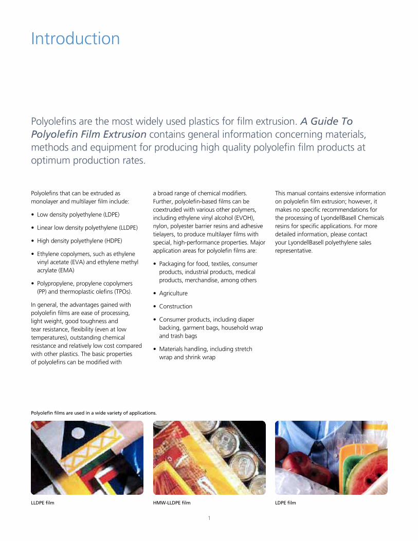
LLDPE film
Polyolefin films are used in a wide variety of applications.
HMW-LLDPE film LDPE film
This manual contains extensive information on polyolefin film extrusion; however, it makes no specific recommendations for the processing of LyondellBasell Chemicals resins for specific applications. For more detailed information, please contact your LyondellBasell polyethylene sales representative.
Polyolefins AreThermoplastics DerivedFrom Petrochemicals
Polyolefins are plastic resins polymerized from petroleum-based gases. The two principal gases are ethylene and propylene.
2
Ethylene is the principal raw material for making polyethylene (PE) and ethylene copolymer resins; and propylene is the main ingredient for making polypropylene (PP) and propylene copolymer resins. Polyolefin resins are classified as thermoplastics, which means that they can be melted, solidified and melted again. This contrasts with thermoset resins which, once molded, cannot be reprocessed.
Most polyolefin resins for film extrusion generally are used in pellet form. The pellets are about 1/8 inch thick and 3/16 inch in diameter, usually somewhat translucent and white in color. Polyolefin resins sometimes will contain additives, such as thermal stabilizers. They also can be compounded with colorants, antistatic agents, slip and antiblock
Molecular Structure and Composition Affect Properties and Processability
Three basic molecular properties affect most of the properties essential to high quality film extrusion:
• Average Molecular Weight
• Molecular Weight Distribution
• Crystallinity or Density.
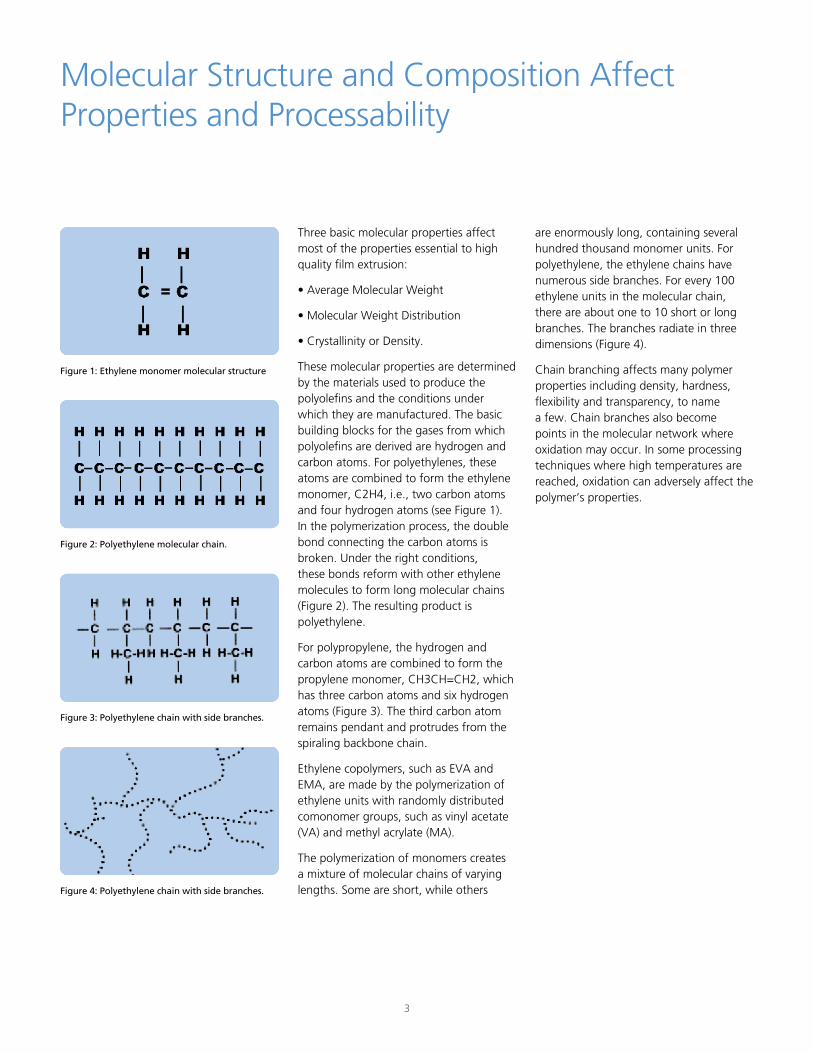
These molecular properties are determined by the materials used to produce the polyolefins and the conditions under which they are manufactured. The basic building blocks for the gases from which polyolefins are derived are hydrogen and carbon atoms. For polyethylenes, these atoms are combined to form the ethylene monomer, C2H4, i.e., two carbon atoms and four hydrogen atoms (see Figure 1). In the polymerization process, the double bond connecting the carbon atoms is broken. Under the right conditions, these bonds reform with other ethylene molecules to form long molecular chains (Figure 2). The resulting product is polyethylene.
For polypropylene, the hydrogen and carbon atoms are combined to form the propylene monomer, CH3CH=CH2, which has three carbon atoms and six hydrogen atoms (Figure 3). The third carbon atom remains pendant and protrudes from the spiraling backbone chain.
Ethylene copolymers, such as EVA and EMA, are made by the polymerization of ethylene units with randomly distributed comonomer groups, such as vinyl acetate (VA) and methyl acrylate (MA).
The polymerization of monomers creates a mixture of molecular chains of varying lengths. Some are short, while others
3
are enormously long, containing several hundred thousand monomer units. For polyethylene, the ethylene chains have numerous side branches. For every 100 ethylene units in the molecular chain, there are about one to 10 short or long branches. The branches radiate in three dimensions (Figure 4).
Chain branching affects many polymer properties including density, hardness, flexibility and transparency, to name a few. Chain branches also become points in the molecular network where oxidation may occur. In some processing techniques where high temperatures are reached, oxidation can adversely affect the polymer’s properties.
Figure 1: Ethylene monomer molecular structure
Figure 2: Polyethylene molecular chain.
Figure 3: Polyethylene chain with side branches.
Figure 4: Polyethylene chain with side branches.
Density
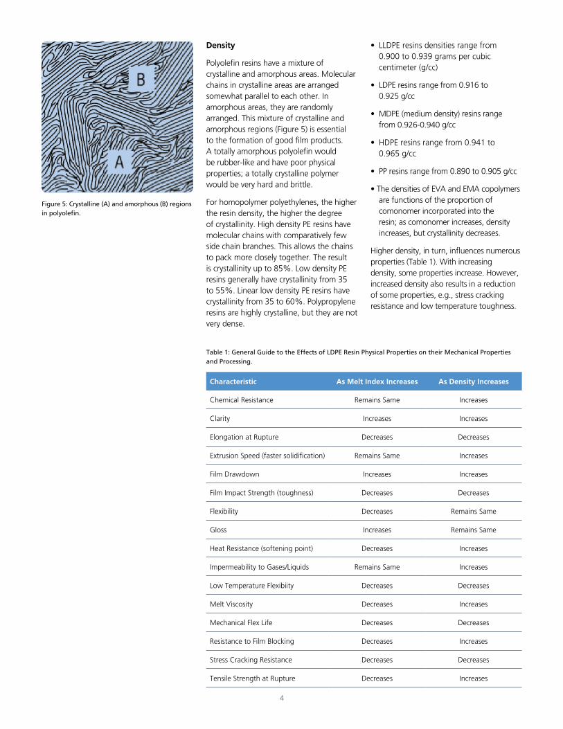
Polyolefin resins have a mixture of crystalline and amorphous areas. Molecular chains in crystalline areas are arranged somewhat parallel to each other. In amorphous areas, they are randomly arranged. This mixture of crystalline and amorphous regions (Figure 5) is essential to the formation of good film products. A totally amorphous polyolefin would be rubber-like and have poor physical properties; a totally crystalline polymer would be very hard and brittle.
For homopolymer polyethylenes, the higher the resin density, the higher the degree of crystallinity. High density PE resins have molecular chains with comparatively few side chain branches. This allows the chains to pack more closely together. The result is crystallinity up to 85%. Low density PE resins generally have crystallinity from 35 to 55%. Linear low density PE resins have crystallinity from 35 to 60%. Polypropylene resins are highly crystalline, but they are not very dense.
4
• LLDPE resins densities range from 0.900 to 0.939 grams per cubic centimeter (g/cc)
• LDPE resins range from 0.916 to 0.925 g/cc
• MDPE (medium density) resins range from 0.926-0.940 g/cc
• HDPE resins range from 0.941 to 0.965 g/cc
• PP resins range from 0.890 to 0.905 g/cc
• The densities of EVA and EMA copolymers are functions of the proportion of comonomer incorporated into the resin; as comonomer increases, density increases, but crystallinity decreases.
Higher density, in turn, influences numerous properties (Table 1). With increasing density, some properties increase. However, increased density also results in a reduction of some properties, e.g., stress cracking resistance and low temperature toughness.
Figure 5: Crystalline (A) and amorphous (B) regions in polyolefin.
Table 1: General Guide to the Effects of LDPE Resin Physical Properties on their Mechanical Properties and Processing.
Characteristic As Melt Index Increases As Density Increases
Chemical Resistance Remains Same Increases
Clarity Increases Increases
Elongation at Rupture Decreases Decreases
Extrusion Speed (faster solidification) Remains Same Increases
Film Drawdown Increases Increases
Film Impact Strength (toughness) Decreases Decreases
Flexibility Decreases Remains Same
Gloss Increases Remains Same
Heat Resistance (softening point) Decreases Increases
Impermeability to Gases/Liquids Remains Same Increases
Low Temperature Flexibiity Decreases Decreases
Melt Viscosity Decreases Increases
Mechanical Flex Life Decreases Decreases
Resistance to Film Blocking Decreases Increases
Stress Cracking Resistance Decreases Decreases
Tensile Strength at Rupture Decreases Increases
Molecular Weight
Molecular Weight Atoms of different elements, such as carbon, hydrogen, etc., have different atomic weights. For carbon, the atomic weight is 12, and for hydrogen it is 1. Thus, the molecular weight of the ethylene unit is the sum of the weight of its six atoms (2 carbon + 4 hydrogen) or 28.
Every polyolefin resin consists of a mixture of large and small chains, i.e., chains of high and low molecular weights. The molecular weight of the polymer chain generally is in the thousands. The average of these is called, quite appropriately, the average molecular weight.
As average molecular weight increases, resin toughness increases. The same holds true for tensile strength and environmental stress cracking resistance (cracking brought on when film is subjected to stresses in the presence of liquids such as solvents, oils, detergents, etc.).
Melt Viscosity
Melt viscosity generally is expressed for polyethylene resins by their melt indices (tested under standard conditions of temperature and pressure). Melt index (MI) is inversely related to the resin’s average molecular weight: as average molecular weight increases, MI decreases. Generally, a polyolefin resin with high molecular weight has a low MI, and vice versa.
Melt viscosity is an extremely important property since it affects the flow of the molten polymer. The resin’s flow when melted increases with increasing MI. Therefore, polyolefins with lower MI require higher extrusion temperatures. It should be remembered that pressure can influence flow properties. Two resins may have the same MI, but different high pressure flow properties. Therefore, MI (Table 2) must be used in conjunction with other yardsticks, such as molecular weight distribution, to measure flow and other properties of resins. Generally, polyolefin film extrusion resins are characterized as having medium, high and very high viscosity.
Molecular Weight Distribution
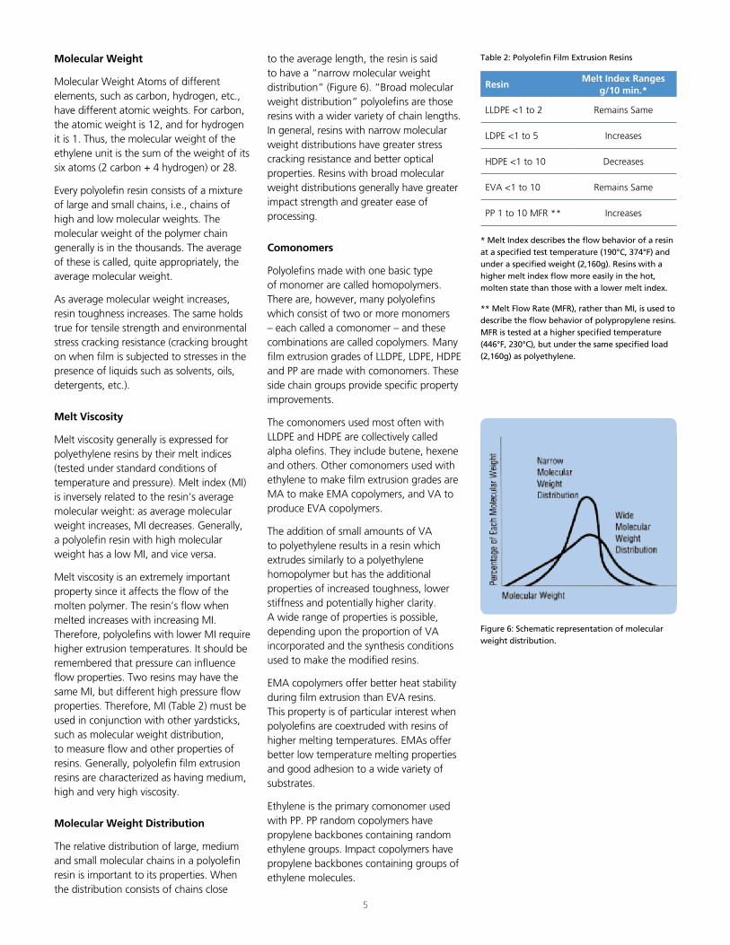
The relative distribution of large, medium and small molecular chains in a polyolefin resin is important to its properties. When the distribution consists of chains close
5
Figure 6: Schematic representation of molecular weight distribution.
Table 2: Polyolefin Film Extrusion Resins
* Melt Index describes the flow behavior of a resin at a specified test temperature (190°C, 374°F) and under a specified weight (2,160g). Resins with a higher melt index flow more easily in the hot, molten state than those with a lower melt index.
** Melt Flow Rate (MFR), rather than MI, is used to describe the flow behavior of polypropylene resins. MFR is tested at a higher specified temperature (446°F, 230°C), but under the same specified load (2,160g) as polyethylene.
ResinMelt Index Ranges
g/10 min.*
LLDPE <1 to 2 Remains Same
LDPE <1 to 5 Increases
HDPE <1 to 10 Decreases
EVA <1 to 10 Remains Same
PP 1 to 10 MFR ** Increases
to the average length, the resin is said to have a “narrow molecular weight distribution” (Figure 6). “Broad molecular weight distribution” polyolefins are those resins with a wider variety of chain lengths. In general, resins with narrow molecular weight distributions have greater stress cracking resistance and better optical properties. Resins with broad molecular weight distributions generally have greater impact strength and greater ease of processing.
Comonomers
Polyolefins made with one basic type of monomer are called homopolymers. There are, however, many polyolefins which consist of two or more monomers – each called a comonomer – and these combinations are called copolymers. Many film extrusion grades of LLDPE, LDPE, HDPE and PP are made with comonomers. These side chain groups provide specific property improvements.
The comonomers used most often with LLDPE and HDPE are collectively called alpha olefins. They include butene, hexene and others. Other comonomers used with ethylene to make film extrusion grades are MA to make EMA copolymers, and VA to produce EVA copolymers.
The addition of small amounts of VA to polyethylene results in a resin which extrudes similarly to a polyethylene homopolymer but has the additional properties of increased toughness, lower stiffness and potentially higher clarity. A wide range of properties is possible, depending upon the proportion of VA incorporated and the synthesis conditions used to make the modified resins.
EMA copolymers offer better heat stability during film extrusion than EVA resins. This property is of particular interest when polyolefins are coextruded with resins of higher melting temperatures. EMAs offer better low temperature melting properties and good adhesion to a wide variety of substrates.
Ethylene is the primary comonomer used with PP. PP random copolymers have propylene backbones containing random ethylene groups. Impact copolymers have propylene backbones containing groups of ethylene molecules.
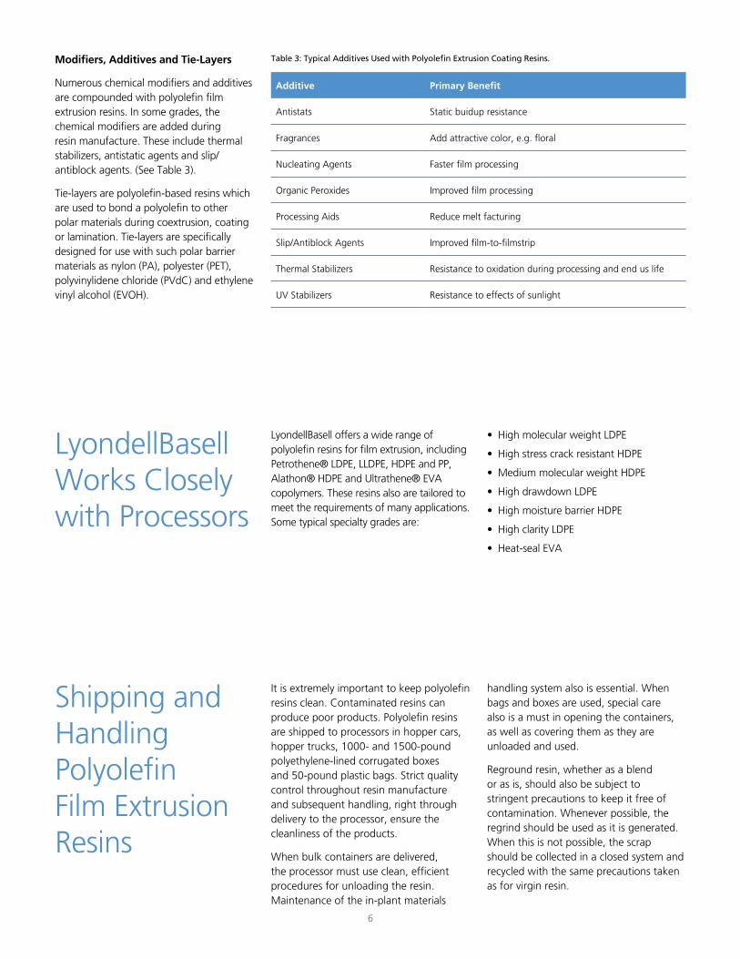
Modifiers, Additives and Tie-Layers
Numerous chemical modifiers and additives are compounded with polyolefin film extrusion resins. In some grades, the chemical modifiers are added during resin manufacture. These include thermal stabilizers, antistatic agents and slip/antiblock agents. (See Table 3).
Tie-layers are polyolefin-based resins which are used to bond a polyolefin to other polar materials during coextrusion, coating or lamination. Tie-layers are specifically designed for use with such polar barrier materials as nylon (PA), polyester (PET), polyvinylidene chloride (PVdC) and ethylene vinyl alcohol (EVOH).
6
Table 3: Typical Additives Used with Polyolefin Extrusion Coating Resins.
Additive Primary Benefit
Antistats Static buidup resistance
Fragrances Add attractive color, e.g. floral
Nucleating Agents Faster film processing
Organic Peroxides Improved film processing
Processing Aids Reduce melt facturing
Slip/Antiblock Agents Improved film-to-filmstrip
Thermal Stabilizers Resistance to oxidation during processing and end us life
UV Stabilizers Resistance to effects of sunlight
LyondellBasell Works Closely with Processors
Shipping and Handling PolyolefinFilm Extrusion Resins
It is extremely important to keep polyolefin resins clean. Contaminated resins can produce poor products. Polyolefin resins are shipped to processors in hopper cars, hopper trucks, 1000- and 1500-pound polyethylene-lined corrugated boxes and 50-pound plastic bags. Strict quality control throughout resin manufacture and subsequent handling, right through delivery to the processor, ensure the cleanliness of the products.
When bulk containers are delivered, the processor must use clean, efficient procedures for unloading the resin. Maintenance of the in-plant materials
LyondellBasell offers a wide range of polyolefin resins for film extrusion, including Petrothene® LDPE, LLDPE, HDPE and PP, Alathon® HDPE and Ultrathene® EVA copolymers. These resins also are tailored to meet the requirements of many applications. Some typical specialty grades are:
• High molecular weight LDPE
• High stress crack resistant HDPE
• Medium molecular weight HDPE
• High drawdown LDPE
• High moisture barrier HDPE
• High clarity LDPE
• Heat-seal EVA
handling system also is essential. When bags and boxes are used, special care also is a must in opening the containers, as well as covering them as they are unloaded and used.
Reground resin, whether as a blend or as is, should also be subject to stringent precautions to keep it free of contamination. Whenever possible, the regrind should be used as it is generated. When this is not possible, the scrap should be collected in a closed system and recycled with the same precautions taken as for virgin resin.
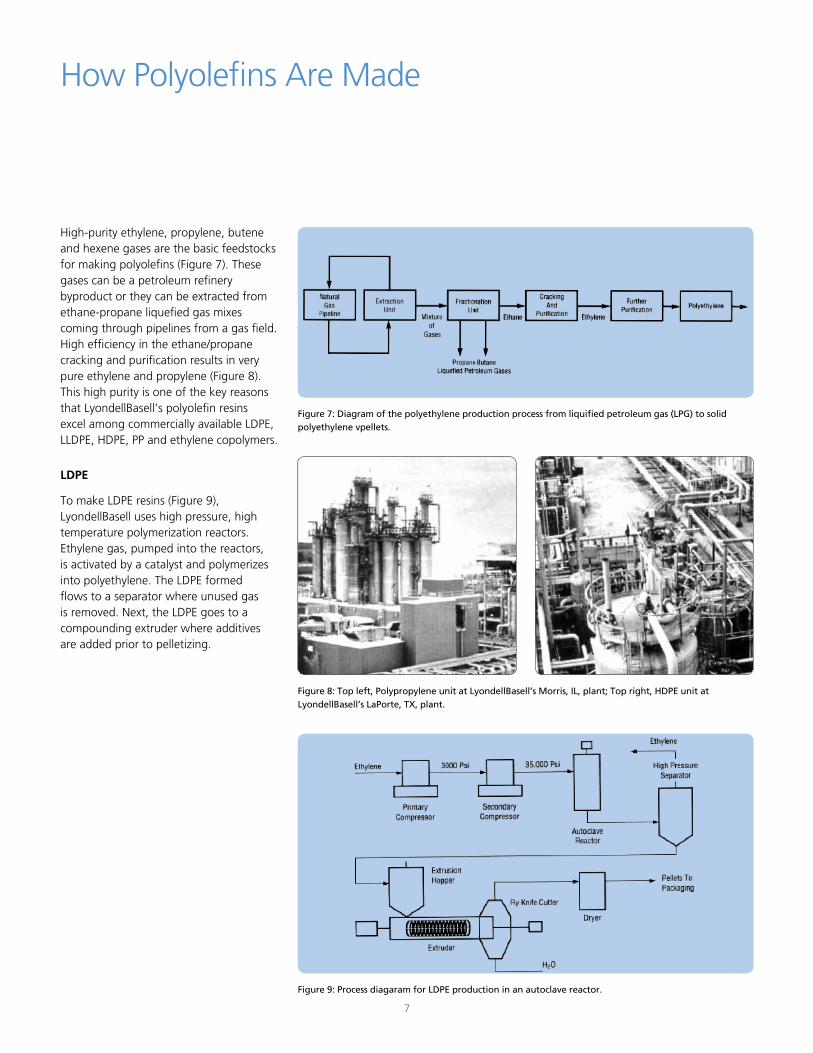
High-purity ethylene, propylene, butene and hexene gases are the basic feedstocks for making polyolefins (Figure 7). These gases can be a petroleum refinery byproduct or they can be extracted from ethane-propane liquefied gas mixes coming through pipelines from a gas field. High efficiency in the ethane/propane cracking and purification results in very pure ethylene and propylene (Figure 8). This high purity is one of the key reasons that LyondellBasell’s polyolefin resins excel among commercially available LDPE, LLDPE, HDPE, PP and ethylene copolymers.
LDPE
To make LDPE resins (Figure 9), LyondellBasell uses high pressure, high temperature polymerization reactors. Ethylene gas, pumped into the reactors, is activated by a catalyst and polymerizes into polyethylene. The LDPE formed flows to a separator where unused gas is removed. Next, the LDPE goes to a compounding extruder where additives are added prior to pelletizing.
7
How Polyolefins Are Made
Figure 7: Diagram of the polyethylene production process from liquified petroleum gas (LPG) to solid polyethylene vpellets.
Figure 9: Process diagaram for LDPE production in an autoclave reactor.
Figure 8: Top left, Polypropylene unit at LyondellBasell’s Morris, IL, plant; Top right, HDPE unit at LyondellBasell’s LaPorte, TX, plant.
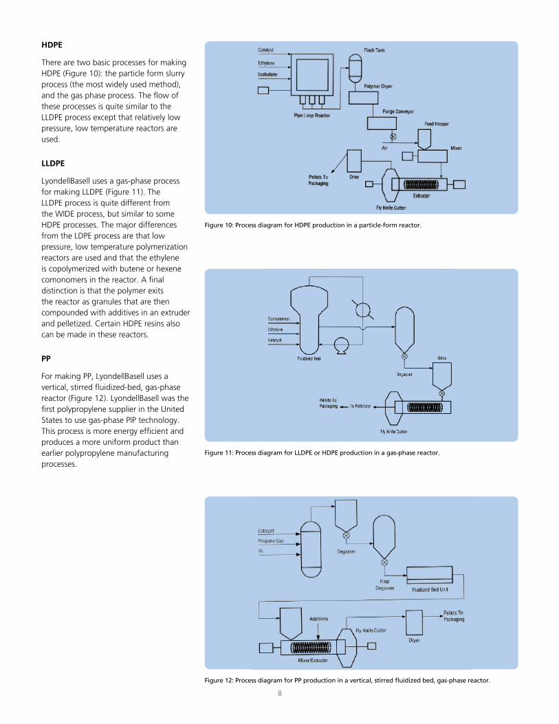
HDPE
There are two basic processes for making HDPE (Figure 10): the particle form slurry process (the most widely used method), and the gas phase process. The flow of these processes is quite similar to the LLDPE process except that relatively low pressure, low temperature reactors are used.
LLDPE
LyondellBasell uses a gas-phase process for making LLDPE (Figure 11). The LLDPE process is quite different from the WIDE process, but similar to some HDPE processes. The major differences from the LDPE process are that low pressure, low temperature polymerization reactors are used and that the ethylene is copolymerized with butene or hexene comonomers in the reactor. A final distinction is that the polymer exits the reactor as granules that are then compounded with additives in an extruder and pelletized. Certain HDPE resins also can be made in these reactors.
PP
For making PP, LyondellBasell uses a vertical, stirred fluidized-bed, gas-phase reactor (Figure 12). LyondellBasell was the first polypropylene supplier in the United States to use gas-phase PIP technology. This process is more energy efficient and produces a more uniform product than earlier polypropylene manufacturing processes.
8
Figure 10: Process diagram for HDPE production in a particle-form reactor.
Figure 11: Process diagram for LLDPE or HDPE production in a gas-phase reactor.
Figure 12: Process diagram for PP production in a vertical, stirred fluidized bed, gas-phase reactor.
There are three basic stages in the overall film extrusion process:
1. Materials Conditioning/Handling
2. Film Extrusion
3. Film Takeoff
Materials Conditioning/Handling
At its resin manufacturing plants, LyondellBasell has extensive systems, such as filters, cyclones, elutriators, etc. to prevent resin contamination during production, storage, loading and shipment. Since polyolefin resins are non-hygroscopic (they absorb virtually no water), they do not require drying prior to extrusion. However, precautions should be taken to ensure the cleanliness of the polyolefin pellets as they are handled at the processor’s facilities.
One way to decrease problems in processing polyolefin resin is to prevent contaminants from entering transfer systems. Whenever a polyolefin resin is moved by a current of air through transfer piping, the possibility of contamination exists. Dust, fines, streamers and angel hair can be generated and plug filters or other components of the transfer system that results in starvation of the extruder. Occasionally, large clumps of angel hair or streamers may accumulate in a silo and plug the exit port. All of these problems can result in extruder downtime, excessive
9
The Film Extrusion Process
scrap and the time and work force costs of cleaning silos, transfer lines and filters.
Many transfer systems consist of smooth bore piping that conveys the resin from hopper cars to storage silos or holding bins. Some transfer systems may include long radius bends. A polyolefin pellet conveyed by forced air through such a transfer line travels at a very high velocity. As the pellet comes in contact with the smooth pipe wall, it slides and slows down due to friction. The friction, in turn, creates sufficient heat to raise the pellet’s surface temperature to the resin’s melting point. As this happens, a small deposit of molten polyolefin is left on the pipe wall. This deposit solidifies almost instantly. Overtime, these deposits buildup and are called “angel hair” when they slough off and are found mixed with the pellets.
As the pellets continuously come in contact with the pipe wall, such as along the curved outside surface of a long radius bend, the deposits of polyolefin become almost continuous and long streamers are formed. Eventually, the angel hair and streamers are dislodged from the pipe wall and find their way into the extrusion process, the storage silo or the transfer filters. The size and number of streamers formed increase with increases in conveying air temperature and velocity and are also greater with smooth bore piping than with other kinds of handling systems.
Materials Handling Equipment Design
Since smooth piping is a leading contributor to angel hair and streamers, the logical solution is to roughen the interior wall of the piping. This roughness will cause the pellets to tumble instead of slide along the pipe, thus decreasing streamer formation. However, as a rapidly moving polyolefin pellet comes in contact with an extremely rough surface, small particles break oft, and fines or dust are created.
Two specific finishes for materials handling piping have proven to be the best performers and give the longest life; the first is a sand blasted finish of 600 to 700 RMS roughness. This finish is probably the easiest to obtain; however, until they become rounded with use, the initial sharp edges of the finish will result in dust and fines.
The other finish is achieved by shot blasting using a #55 shot with 55-60 Rockwell hardness to produce a 900 RMS roughness. Variations of this finish are commonly known as “hammer finished” surfaces. The shot blasting allows deeper penetration and increases hardness, which in turn, leads to longer surface life. The rounded edges obtained minimize the initial problems encountered with dust and fines. They also reduce metal contamination possibilities associated with the sandblasted finish.
Whenever a new transfer system is installed or when a portion of an existing system is replaced, the interior surfaces should be treated either by sand or shot blasting. The initial cost is far outweighed by the prevention of future problems.
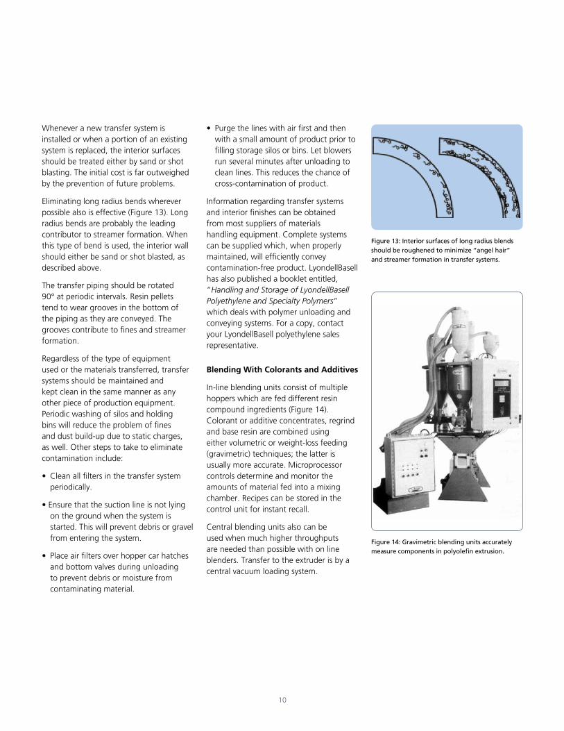
Eliminating long radius bends wherever possible also is effective (Figure 13). Long radius bends are probably the leading contributor to streamer formation. When this type of bend is used, the interior wall should either be sand or shot blasted, as described above.
The transfer piping should be rotated 90° at periodic intervals. Resin pellets tend to wear grooves in the bottom of the piping as they are conveyed. The grooves contribute to fines and streamer formation.
Regardless of the type of equipment used or the materials transferred, transfer systems should be maintained and kept clean in the same manner as any other piece of production equipment. Periodic washing of silos and holding bins will reduce the problem of fines and dust build-up due to static charges, as well. Other steps to take to eliminate contamination include:
• Clean all filters in the transfer system periodically.
• Ensure that the suction line is not lying on the ground when the system is started. This will prevent debris or gravel from entering the system.
• Place air filters over hopper car hatches and bottom valves during unloading to prevent debris or moisture from contaminating material.
10
• Purge the lines with air first and then with a small amount of product prior to filling storage silos or bins. Let blowers run several minutes after unloading to clean lines. This reduces the chance of cross-contamination of product.
Information regarding transfer systems and interior finishes can be obtained from most suppliers of materials handling equipment. Complete systems can be supplied which, when properly maintained, will efficiently convey contamination-free product. LyondellBasell has also published a booklet entitled, “Handling and Storage of LyondellBasell Polyethylene and Specialty Polymers” which deals with polymer unloading and conveying systems. For a copy, contact your LyondellBasell polyethylene sales representative.
Blending With Colorants and Additives
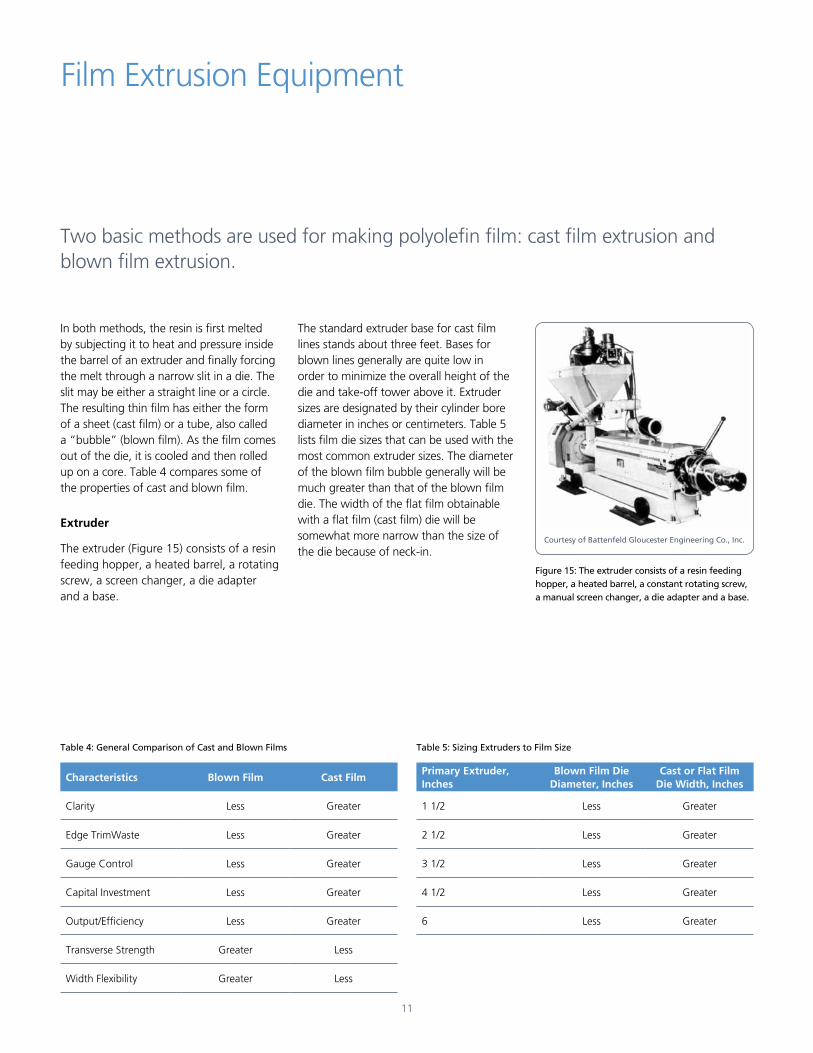
In-line blending units consist of multiple hoppers which are fed different resin compound ingredients (Figure 14). Colorant or additive concentrates, regrind and base resin are combined using either volumetric or weight-loss feeding (gravimetric) techniques; the latter is usually more accurate. Microprocessor controls determine and monitor the amounts of material fed into a mixing chamber. Recipes can be stored in the control unit for instant recall.
Central blending units also can be used when much higher throughputs are needed than possible with on line blenders. Transfer to the extruder is by a central vacuum loading system.
Figure 14: Gravimetric blending units accurately measure components in polyolefin extrusion.
Figure 13: Interior surfaces of long radius blends should be roughened to minimize “angel hair” and streamer formation in transfer systems.
In both methods, the resin is first melted by subjecting it to heat and pressure inside the barrel of an extruder and finally forcing the melt through a narrow slit in a die. The slit may be either a straight line or a circle. The resulting thin film has either the form of a sheet (cast film) or a tube, also called a “bubble” (blown film). As the film comes out of the die, it is cooled and then rolled up on a core. Table 4 compares some of the properties of cast and blown film.
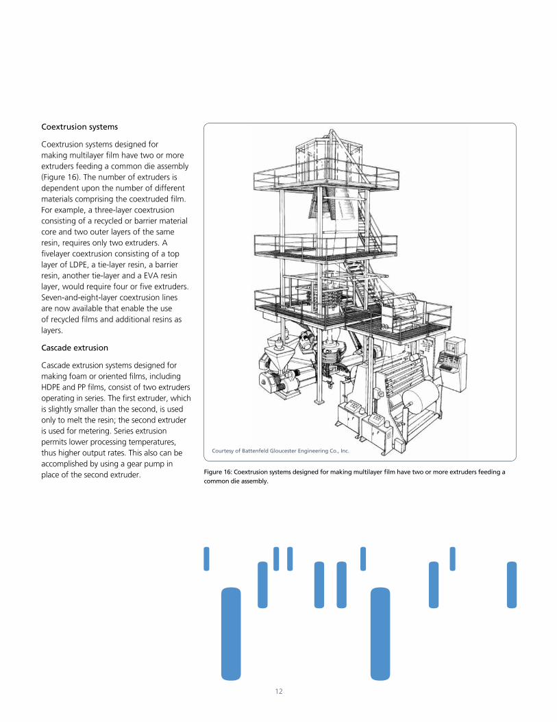
Extruder
The extruder (Figure 15) consists of a resin feeding hopper, a heated barrel, a rotating screw, a screen changer, a die adapter and a base.
11
Film Extrusion Equipment
Table 4: General Comparison of Cast and Blown Films Table 5: Sizing Extruders to Film Size
Characteristics Blown Film Cast Film
Clarity Less Greater
Edge TrimWaste Less Greater
Gauge Control Less Greater
Capital Investment Less Greater
Output/Efficiency Less Greater
Transverse Strength Greater Less
Width Flexibility Greater Less
Primary Extruder, Inches
Blown Film Die Diameter, Inches
Cast or Flat Film Die Width, Inches
1 1/2 Less Greater
2 1/2 Less Greater
3 1/2 Less Greater
4 1/2 Less Greater
6 Less Greater
Figure 15: The extruder consists of a resin feeding hopper, a heated barrel, a constant rotating screw, a manual screen changer, a die adapter and a base.
Courtesy of Battenfeld Gloucester Engineering Co., Inc.
The standard extruder base for cast film lines stands about three feet. Bases for blown lines generally are quite low in order to minimize the overall height of the die and take-off tower above it. Extruder sizes are designated by their cylinder bore diameter in inches or centimeters. Table 5 lists film die sizes that can be used with the most common extruder sizes. The diameter of the blown film bubble generally will be much greater than that of the blown film die. The width of the flat film obtainable with a flat film (cast film) die will be somewhat more narrow than the size of the die because of neck-in.
Two basic methods are used for making polyolefin film: cast film extrusion and blown film extrusion.
Coextrusion systems
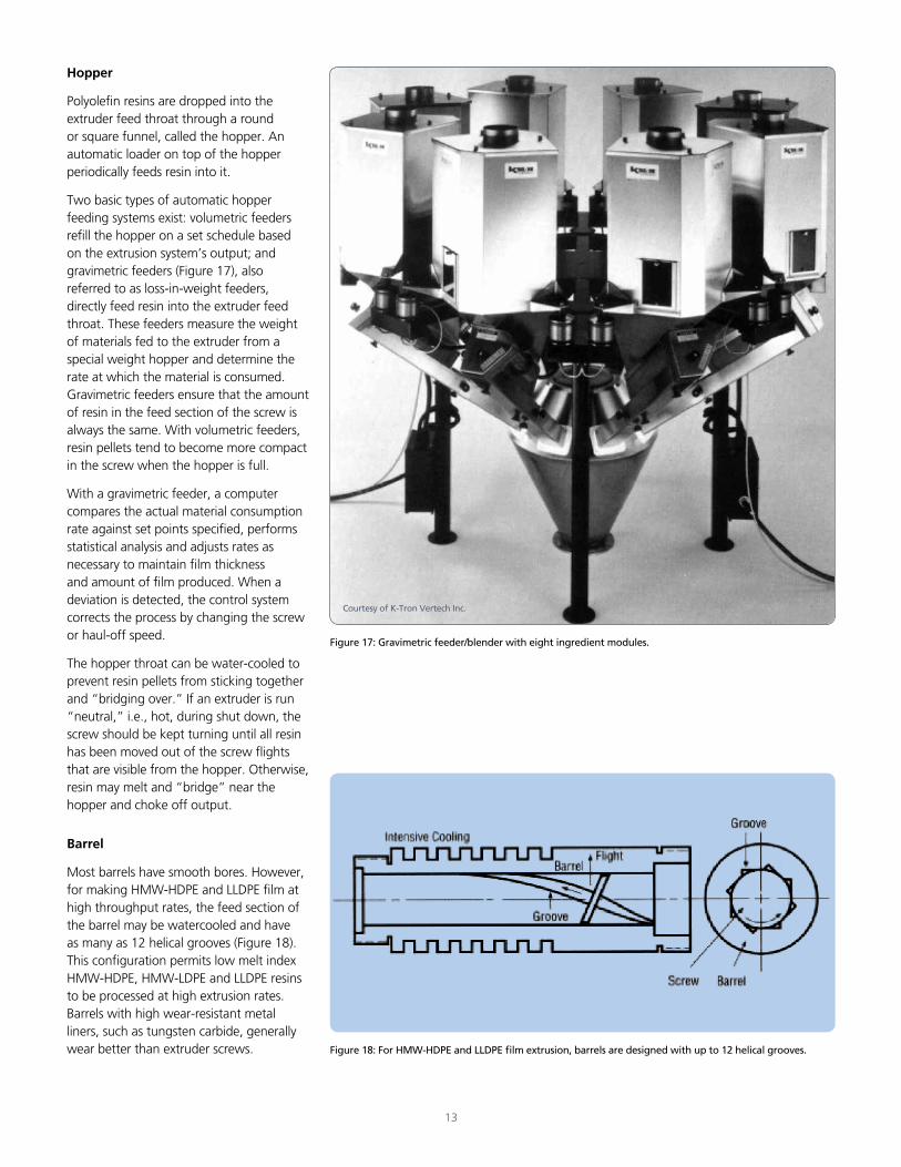
Coextrusion systems designed for making multilayer film have two or more extruders feeding a common die assembly (Figure 16). The number of extruders is dependent upon the number of different materials comprising the coextruded film. For example, a three-layer coextrusion consisting of a recycled or barrier material core and two outer layers of the same resin, requires only two extruders. A fivelayer coextrusion consisting of a top layer of LDPE, a tie-layer resin, a barrier resin, another tie-layer and a EVA resin layer, would require four or five extruders. Seven-and-eight-layer coextrusion lines are now available that enable the use of recycled films and additional resins as layers.
Cascade extrusion
Cascade extrusion systems designed for making foam or oriented films, including HDPE and PP films, consist of two extruders operating in series. The first extruder, which is slightly smaller than the second, is used only to melt the resin; the second extruder is used for metering. Series extrusion permits lower processing temperatures, thus higher output rates. This also can be accomplished by using a gear pump in place of the second extruder.
12
Figure 16: Coextrusion systems designed for making multilayer film have two or more extruders feeding a common die assembly.
Courtesy of Battenfeld Gloucester Engineering Co., Inc.
Hopper
Polyolefin resins are dropped into the extruder feed throat through a round or square funnel, called the hopper. An automatic loader on top of the hopper periodically feeds resin into it.
Two basic types of automatic hopper feeding systems exist: volumetric feeders refill the hopper on a set schedule based on the extrusion system’s output; and gravimetric feeders (Figure 17), also referred to as loss-in-weight feeders, directly feed resin into the extruder feed throat. These feeders measure the weight of materials fed to the extruder from a special weight hopper and determine the rate at which the material is consumed. Gravimetric feeders ensure that the amount of resin in the feed section of the screw is always the same. With volumetric feeders, resin pellets tend to become more compact in the screw when the hopper is full.
With a gravimetric feeder, a computer compares the actual material consumption rate against set points specified, performs statistical analysis and adjusts rates as necessary to maintain film thickness and amount of film produced. When a deviation is detected, the control system corrects the process by changing the screw or haul-off speed.
The hopper throat can be water-cooled to prevent resin pellets from sticking together and “bridging over.” If an extruder is run “neutral,” i.e., hot, during shut down, the screw should be kept turning until all resin has been moved out of the screw flights that are visible from the hopper. Otherwise, resin may melt and “bridge” near the hopper and choke off output.
Barrel
Most barrels have smooth bores. However, for making HMW-HDPE and LLDPE film at high throughput rates, the feed section of the barrel may be watercooled and have as many as 12 helical grooves (Figure 18). This configuration permits low melt index HMW-HDPE, HMW-LDPE and LLDPE resins to be processed at high extrusion rates. Barrels with high wear-resistant metal liners, such as tungsten carbide, generally wear better than extruder screws.
13
Figure 17: Gravimetric feeder/blender with eight ingredient modules.
Figure 18: For HMW-HDPE and LLDPE film extrusion, barrels are designed with up to 12 helical grooves.
Courtesy of K-Tron Vertech Inc.
Heaters
For fast extruder start-up, barrel heating is necessary and usually done by electrical barrel heating bands. They respond rapidly, are easy to adjust and require a minimum of maintenance. The heater bands are distributed along the barrel length in what are called zones. Generally, the barrel is divided into three to six zones. Blowers in each zone decrease the heat when necessary and rapidly cool the barrel when the extruder is to be shut down. Water-cooled zones also are used by some manufacturers for faster heat transfer.
Thermocouples
Thermocouples are inserted deep into the barrel wall, and in some cases even into the melt, to monitor processing temperature. Signals from the thermocouples activate temperature controlling mechanisms to regulate the heater bands and cooling devices. Regular maintenance checks should be made to detect loose-fitting, broken or damaged thermocouples or wires.
14
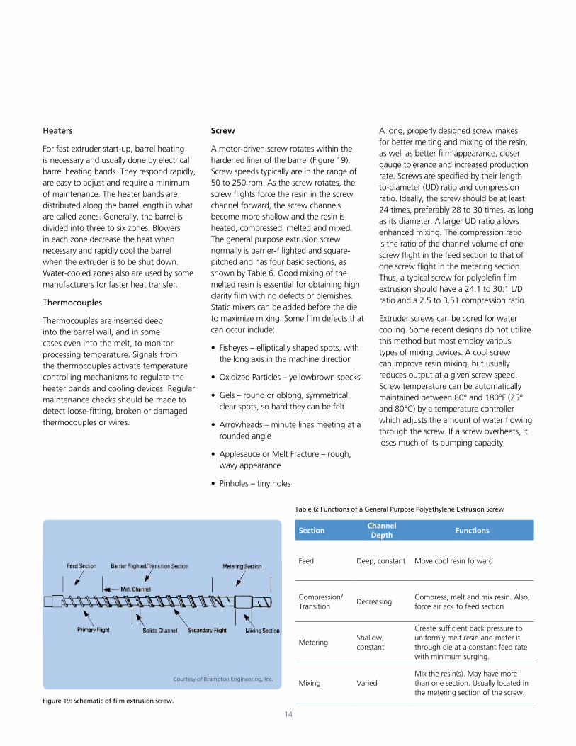
Figure 19: Schematic of film extrusion screw.
Courtesy of Brampton Engineering, Inc.
Screw
A motor-driven screw rotates within the hardened liner of the barrel (Figure 19). Screw speeds typically are in the range of 50 to 250 rpm. As the screw rotates, the screw flights force the resin in the screw channel forward, the screw channels become more shallow and the resin is heated, compressed, melted and mixed. The general purpose extrusion screw normally is barrier-f lighted and square-pitched and has four basic sections, as shown by Table 6. Good mixing of the melted resin is essential for obtaining high clarity film with no defects or blemishes. Static mixers can be added before the die to maximize mixing. Some film defects that can occur include:
• Fisheyes – elliptically shaped spots, with the long axis in the machine direction
• Oxidized Particles – yellowbrown specks
• Gels – round or oblong, symmetrical, clear spots, so hard they can be felt
• Arrowheads – minute lines meeting at a rounded angle
• Applesauce or Melt Fracture – rough, wavy appearance
• Pinholes – tiny holes
A long, properly designed screw makes for better melting and mixing of the resin, as well as better film appearance, closer gauge tolerance and increased production rate. Screws are specified by their length to-diameter (UD) ratio and compression ratio. Ideally, the screw should be at least 24 times, preferably 28 to 30 times, as long as its diameter. A larger UD ratio allows enhanced mixing. The compression ratio is the ratio of the channel volume of one screw flight in the feed section to that of one screw flight in the metering section. Thus, a typical screw for polyolefin film extrusion should have a 24:1 to 30:1 L/D ratio and a 2.5 to 3.51 compression ratio.
Extruder screws can be cored for water cooling. Some recent designs do not utilize this method but most employ various types of mixing devices. A cool screw can improve resin mixing, but usually reduces output at a given screw speed. Screw temperature can be automatically maintained between 80° and 180°F (25° and 80°C) by a temperature controller which adjusts the amount of water flowing through the screw. If a screw overheats, it loses much of its pumping capacity.
Table 6: Functions of a General Purpose Polyethylene Extrusion Screw
SectionChannel Depth
Functions
Feed Deep, constant Move cool resin forward
Compression/Transition
DecreasingCompress, melt and mix resin. Also, force air ack to feed section
MeteringShallow, constant
Create sufficient back pressure to uniformly melt resin and meter it through die at a constant feed rate with minimum surging.
Mixing VariedMix the resin(s). May have more than one section. Usually located in the metering section of the screw.
Mixing Screws
For some polyolefins, additional mixing is required of the screw (Table 7). Mixing screws have the same three sections as general purpose screws, but they also have a fourth mixing section. The mixing section can have various configurations designed for dispersive mixing. Another design gives the screw two mixing sections: one at the end of the metering section and one near the end of the compression section.
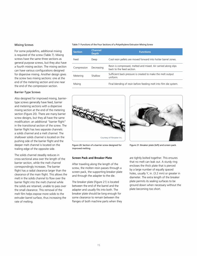
Barrier-Type Screws
Also designed for improved mixing, barrier-type screws generally have feed, barrier and metering sections with a dispersive mixing section at the end of the metering section (Figure 20). There are many barrier screw designs, but they all have the same modification: an additional “barrier flight” in the transitional section of the screw. The barrier flight has two separate channels: a solids channel and a melt channel. The shallower solids channel is located on the pushing side of the barrier flight and the deeper melt channel is located on the trailing edge of the opposite side.
The solids channel steadily reduces in cross-sectional area over the length of the barrier section, while the melt channel correspondingly increases. The barrier flight has a radial clearance larger than the clearance of the main flight. This allows the melt in the solids channel to flow over the barrier flight into the melt channel while the solids are retained, unable to pass over the small clearance. This removal of the melt film helps expose more solids to the extruder barrel surface, thus increasing the rate of melting.
15
Figure 20: Section of a barrier screw designed for improved melting.
Figure 21: Breaker plate (left) and screen pack.
Courtesy of Filmaster Inc.
Screen Pack and Breaker Plate
After traveling along the length of the screw, the molten resin passes through a screen pack, the supporting breaker plate and through the adapter to the die.
The breaker plate (Figure 21) is located between the end of the barrel and the adapter and usually fits into both. The breaker plate should be long enough for some clearance to remain between the flanges of both machine parts when they
are tightly bolted together. This ensures that no melt can leak out. A sturdy ring encloses the thick plate that is pierced by a large number of equally spaced holes, usually Y, in. (3.2 mm) or greater in diameter. The extra length of the breaker plate permits its sealing surfaces to be ground down when necessary without the plate becoming too short.
Table 7: Functions of the Four Sections of a Polyethylene Extrusion Mixing Screw
SectionChannel Depth
Functions
Feed Deep Cool resin pellets are moved forward into hotter barrel zones.
Compression DecreasingResin is compressed, melted and mixed. Air carried along slips back to the feed section.
Metering ShallowSufficient back pressure is created to make the melt output uniform.
Mixing Final blending of resin before feeding melt into film die system.
16
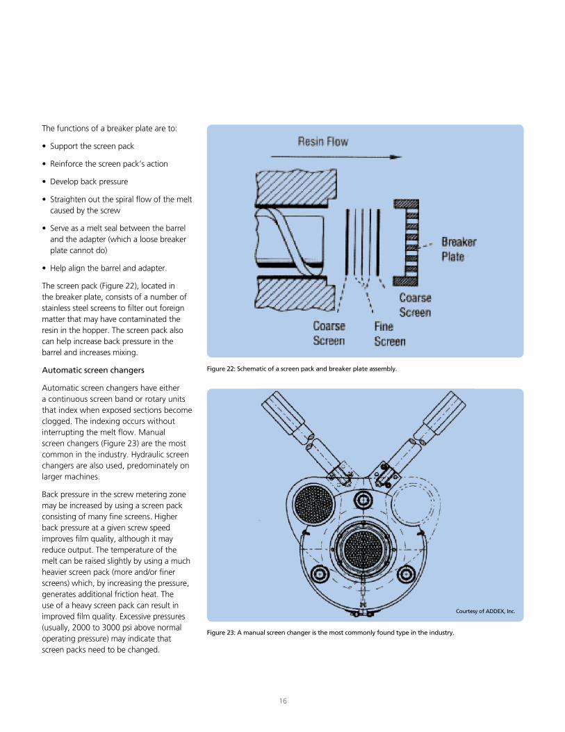
The functions of a breaker plate are to:
• Support the screen pack
• Reinforce the screen pack’s action
• Develop back pressure
• Straighten out the spiral flow of the melt caused by the screw
• Serve as a melt seal between the barrel and the adapter (which a loose breaker plate cannot do)
• Help align the barrel and adapter.
The screen pack (Figure 22), located in the breaker plate, consists of a number of stainless steel screens to filter out foreign matter that may have contaminated the resin in the hopper. The screen pack also can help increase back pressure in the barrel and increases mixing.
Automatic screen changers
Automatic screen changers have either a continuous screen band or rotary units that index when exposed sections become clogged. The indexing occurs without interrupting the melt flow. Manual screen changers (Figure 23) are the most common in the industry. Hydraulic screen changers are also used, predominately on larger machines.
Back pressure in the screw metering zone may be increased by using a screen pack consisting of many fine screens. Higher back pressure at a given screw speed improves film quality, although it may reduce output. The temperature of the melt can be raised slightly by using a much heavier screen pack (more and/or finer screens) which, by increasing the pressure, generates additional friction heat. The use of a heavy screen pack can result in improved film quality. Excessive pressures (usually, 2000 to 3000 psi above normal operating pressure) may indicate that screen packs need to be changed.
Figure 22: Schematic of a screen pack and breaker plate assembly.
Figure 23: A manual screen changer is the most commonly found type in the industry.
Courtesy of ADDEX, Inc.
17
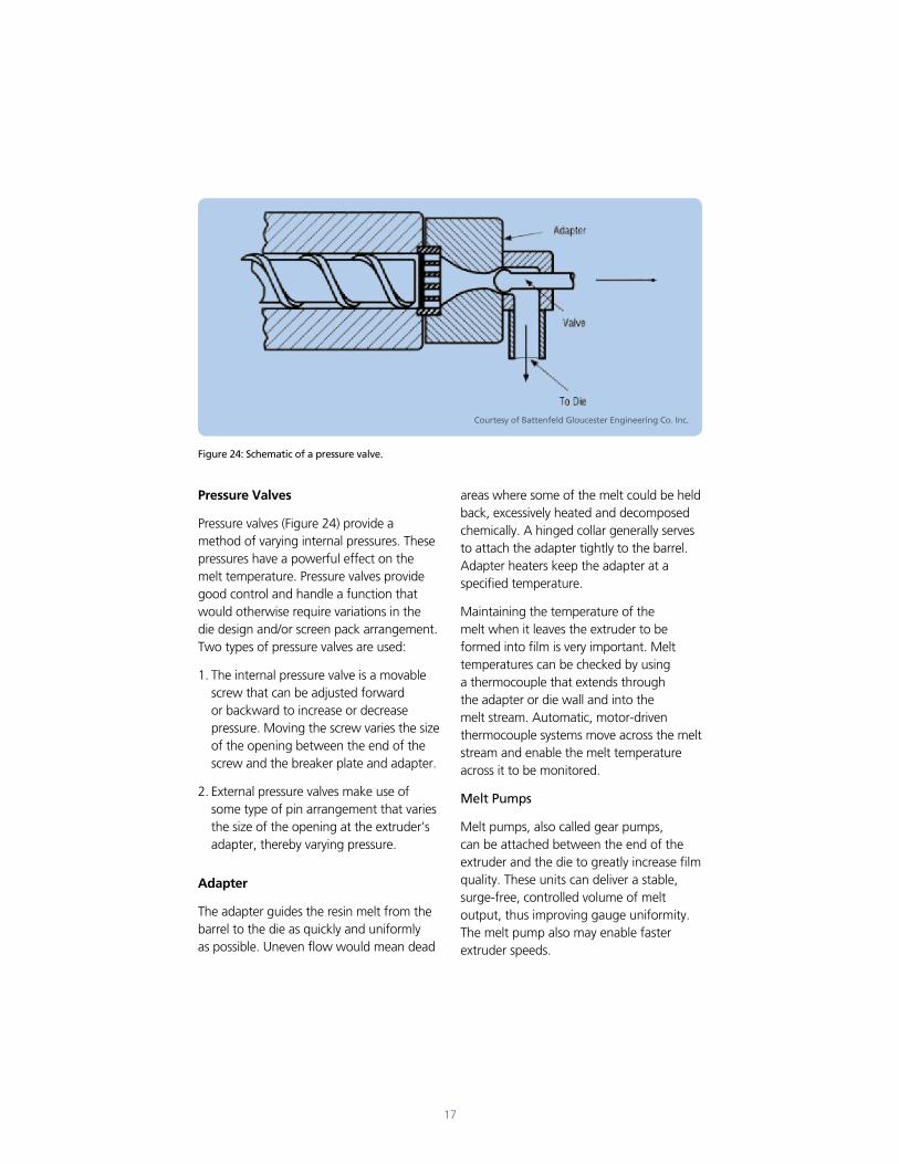
Pressure Valves
Pressure valves (Figure 24) provide a method of varying internal pressures. These pressures have a powerful effect on the melt temperature. Pressure valves provide good control and handle a function that would otherwise require variations in the die design and/or screen pack arrangement. Two types of pressure valves are used:
1. The internal pressure valve is a movable screw that can be adjusted forward or backward to increase or decrease pressure. Moving the screw varies the size of the opening between the end of the screw and the breaker plate and adapter.
2. External pressure valves make use of some type of pin arrangement that varies the size of the opening at the extruder’s adapter, thereby varying pressure.
Adapter
The adapter guides the resin melt from the barrel to the die as quickly and uniformly as possible. Uneven flow would mean dead
Figure 24: Schematic of a pressure valve.
areas where some of the melt could be held back, excessively heated and decomposed chemically. A hinged collar generally serves to attach the adapter tightly to the barrel. Adapter heaters keep the adapter at a specified temperature.
Maintaining the temperature of the melt when it leaves the extruder to be formed into film is very important. Melt temperatures can be checked by using a thermocouple that extends through the adapter or die wall and into the melt stream. Automatic, motor-driven thermocouple systems move across the melt stream and enable the melt temperature across it to be monitored.
Melt Pumps
Melt pumps, also called gear pumps, can be attached between the end of the extruder and the die to greatly increase film quality. These units can deliver a stable, surge-free, controlled volume of melt output, thus improving gauge uniformity. The melt pump also may enable faster extruder speeds.
Courtesy of Battenfeld Gloucester Engineering Co. Inc.
18
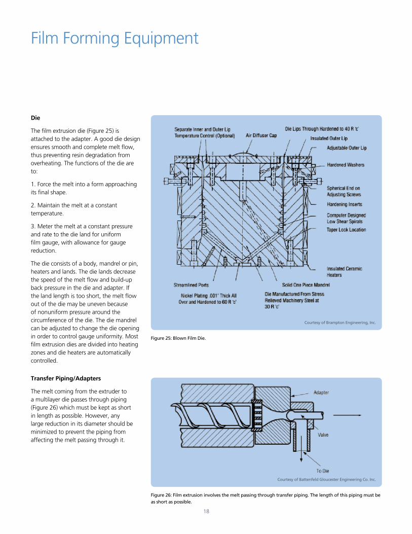
Die
The film extrusion die (Figure 25) is attached to the adapter. A good die design ensures smooth and complete melt flow, thus preventing resin degradation from overheating. The functions of the die are to:
1. Force the melt into a form approaching its final shape.
2. Maintain the melt at a constant temperature.
3. Meter the melt at a constant pressure and rate to the die land for uniform film gauge, with allowance for gauge reduction.
The die consists of a body, mandrel or pin, heaters and lands. The die lands decrease the speed of the melt flow and build-up back pressure in the die and adapter. If the land length is too short, the melt flow out of the die may be uneven because of nonuniform pressure around the circumference of the die. The die mandrel can be adjusted to change the die opening in order to control gauge uniformity. Most film extrusion dies are divided into heating zones and die heaters are automatically controlled.
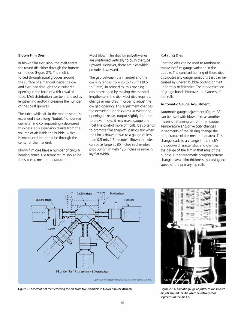
Transfer Piping/Adapters
The melt coming from the extruder to a multilayer die passes through piping (Figure 26) which must be kept as short in length as possible. However, any large reduction in its diameter should be minimized to prevent the piping from affecting the melt passing through it.
Film Forming Equipment
Figure 25: Blown Film Die.
Courtesy of Brampton Engineering, Inc.
Figure 26: Film extrusion involves the melt passing through transfer piping. The length of this piping must be as short as possible.
Courtesy of Battenfeld Gloucester Engineering Co. Inc.
19
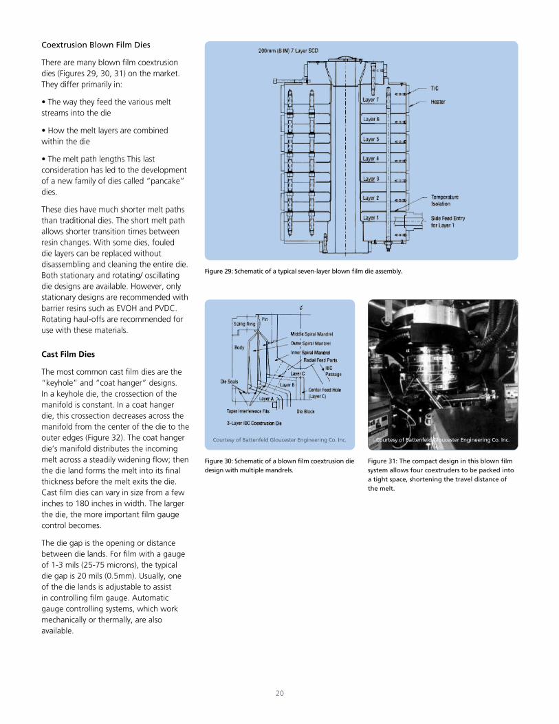
Blown Film Dies
In blown film extrusion, the melt enters the round die either through the bottom or the side (Figure 27). The melt is forced through spiral grooves around the surface of a mandrel inside the die and extruded through the circular die opening in the form of a thick-walled tube. Melt distribution can be improved by lengthening and/or increasing the number of the spiral grooves.
The tube, while still in the molten state, is expanded into a long “bubble” of desired diameter and correspondingly decreased thickness. This expansion results from the volume of air inside the bubble, which is introduced into the tube through the center of the mandrel.
Blown film dies have a number of circular heating zones. Die temperature should be the same as melt temperature.
Figure 27: Schematic of melt entering the die from five extruders in blown film coextrusion.
Courtesy of Battenfeld Gloucester Engineering Co. Inc.
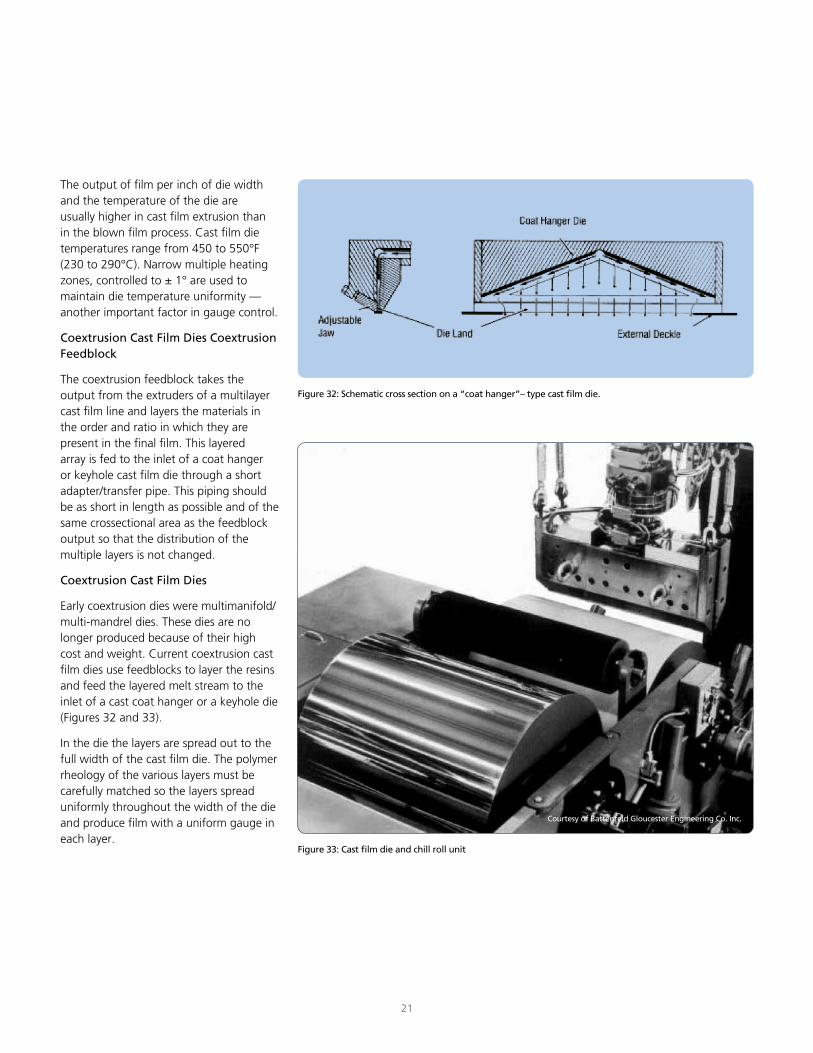
Figure 28: Automatic gauge adjustment can involve air jets around the die which selectively cool segments of the die lip.
Courtesy of W&H Corp.
Most blown film dies for polyethylenes are positioned vertically to push the tube upward. However, there are dies which extrude downward.
The gap between the mandrel and the die ring ranges from 25 to 120 mil (0.5 to 3 mm). In some dies, this opening can be changed by moving the mandrel lengthwise in the die. Most dies require a change in mandrels in order to adjust the die gap opening. This adjustment changes the extruded tube thickness. A wider ring opening increases output slightly, but due to uneven flow, it may make gauge and frost line control more difficult. It also tends to promote film snap-off, particularly when the film is drawn down to a gauge of less than 0.5 mils (13 microns). Blown film dies can be as large as 80 inches in diameter, producing film with 125 inches or more in lay flat width.
Rotating Dies
Rotating dies can be used to randomize transverse film gauge variation in the bubble. The constant turning of these dies distributes any gauge variations that can be caused by uneven bubble cooling or melt uniformity deficiencies. The randomization of gauge bands improves the flatness of film rolls.
Automatic Gauge Adjustment
Automatic gauge adjustment (Figure 28) can be used with blown film as another means of attaining uniform film gauge. Temperature and/or velocity changes in segments of the air ring change the temperature of the melt in that area. This change leads to a change in the melt’s drawdown characteristics and changes the gauge of the film in that area of the bubble. Other automatic gauging systems change overall film thickness by varying the speed of the primary nip rolls.
Coextrusion Blown Film Dies
There are many blown film coextrusion dies (Figures 29, 30, 31) on the market. They differ primarily in:
• The way they feed the various melt streams into the die
• How the melt layers are combined within the die
• The melt path lengths This last consideration has led to the development of a new family of dies called “pancake” dies.
These dies have much shorter melt paths than traditional dies. The short melt path allows shorter transition times between resin changes. With some dies, fouled die layers can be replaced without disassembling and cleaning the entire die. Both stationary and rotating/ oscillating die designs are available. However, only stationary designs are recommended with barrier resins such as EVOH and PVDC. Rotating haul-offs are recommended for use with these materials.
Cast Film Dies
The most common cast film dies are the “keyhole” and “coat hanger” designs. In a keyhole die, the crossection of the manifold is constant. In a coat hanger die, this crossection decreases across the manifold from the center of the die to the outer edges (Figure 32). The coat hanger die’s manifold distributes the incoming melt across a steadily widening flow; then the die land forms the melt into its final thickness before the melt exits the die. Cast film dies can vary in size from a few inches to 180 inches in width. The larger the die, the more important film gauge control becomes.
The die gap is the opening or distance between die lands. For film with a gauge of 1-3 mils (25-75 microns), the typical die gap is 20 mils (0.5mm). Usually, one of the die lands is adjustable to assist in controlling film gauge. Automatic gauge controlling systems, which work mechanically or thermally, are also available.
Figure 30: Schematic of a blown film coextrusion die design with multiple mandrels.
Figure 31: The compact design in this blown film system allows four coextruders to be packed into a tight space, shortening the travel distance of the melt.
Courtesy of Battenfeld Gloucester Engineering Co. Inc. Courtesy of Battenfeld Gloucester Engineering Co. Inc.
Figure 29: Schematic of a typical seven-layer blown film die assembly.
20
The output of film per inch of die width and the temperature of the die are usually higher in cast film extrusion than in the blown film process. Cast film die temperatures range from 450 to 550°F (230 to 290°C). Narrow multiple heating zones, controlled to ± 1° are used to maintain die temperature uniformity — another important factor in gauge control.
Coextrusion Cast Film Dies Coextrusion Feedblock
The coextrusion feedblock takes the output from the extruders of a multilayer cast film line and layers the materials in the order and ratio in which they are present in the final film. This layered array is fed to the inlet of a coat hanger or keyhole cast film die through a short adapter/transfer pipe. This piping should be as short in length as possible and of the same crossectional area as the feedblock output so that the distribution of the multiple layers is not changed.
Coextrusion Cast Film Dies
Early coextrusion dies were multimanifold/multi-mandrel dies. These dies are no longer produced because of their high cost and weight. Current coextrusion cast film dies use feedblocks to layer the resins and feed the layered melt stream to the inlet of a cast coat hanger or a keyhole die (Figures 32 and 33).
In the die the layers are spread out to the full width of the cast film die. The polymer rheology of the various layers must be carefully matched so the layers spread uniformly throughout the width of the die and produce film with a uniform gauge in each layer.
Courtesy of Battenfeld Gloucester Engineering Co. Inc.
Figure 33: Cast film die and chill roll unit
21
Figure 32: Schematic cross section on a “coat hanger”– type cast film die.
22
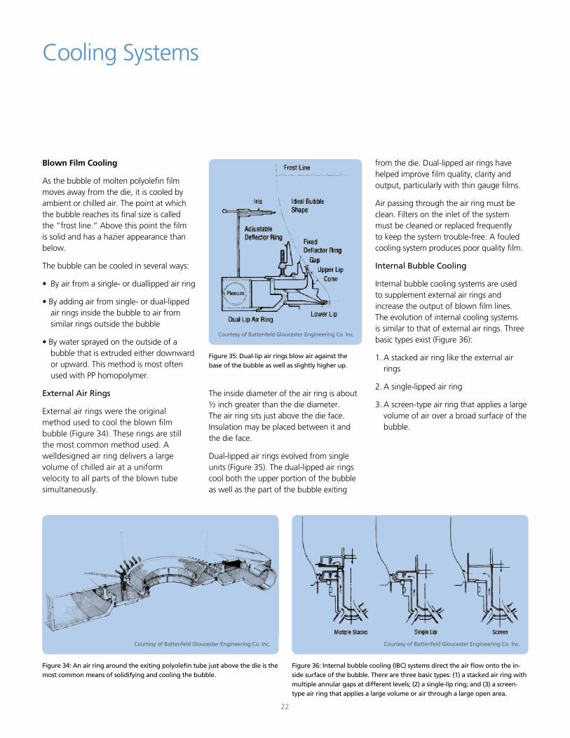
Blown Film Cooling
As the bubble of molten polyolefin film moves away from the die, it is cooled by ambient or chilled air. The point at which the bubble reaches its final size is called the “frost line.” Above this point the film is solid and has a hazier appearance than below.
The bubble can be cooled in several ways:
• By air from a single- or duallipped air ring
• By adding air from single- or dual-lipped air rings inside the bubble to air from similar rings outside the bubble
• By water sprayed on the outside of a bubble that is extruded either downward or upward. This method is most often used with PP homopolymer.
External Air Rings
External air rings were the original method used to cool the blown film bubble (Figure 34). These rings are still the most common method used. A welldesigned air ring delivers a large volume of chilled air at a uniform velocity to all parts of the blown tube simultaneously.
Cooling Systems
The inside diameter of the air ring is about ½ inch greater than the die diameter. The air ring sits just above the die face. Insulation may be placed between it and the die face.
Dual-lipped air rings evolved from single units (Figure 35). The dual-lipped air rings cool both the upper portion of the bubble as well as the part of the bubble exiting
Figure 36: Internal bubble cooling (IBC) systems direct the air flow onto the in-side surface of the bubble. There are three basic types: (1) a stacked air ring with multiple annular gaps at different levels; (2) a single-lip ring; and (3) a screen-type air ring that applies a large volume or air through a large open area.
Figure 34: An air ring around the exiting polyolefin tube just above the die is the most common means of solidifying and cooling the bubble.
Figure 35: Dual-lip air rings blow air against the base of the bubble as well as slightly higher up.
Courtesy of Battenfeld Gloucester Engineering Co. Inc.Courtesy of Battenfeld Gloucester Engineering Co. Inc.
Courtesy of Battenfeld Gloucester Engineering Co. Inc.
from the die. Dual-lipped air rings have helped improve film quality, clarity and output, particularly with thin gauge films.
Air passing through the air ring must be clean. Filters on the inlet of the system must be cleaned or replaced frequently to keep the system trouble-free. A fouled cooling system produces poor quality film.
Internal Bubble Cooling
Internal bubble cooling systems are used to supplement external air rings and increase the output of blown film lines. The evolution of internal cooling systems is similar to that of external air rings. Three basic types exist (Figure 36):
1. A stacked air ring like the external air rings
2. A single-lipped air ring
3. A screen-type air ring that applies a large volume of air over a broad surface of the bubble.
23
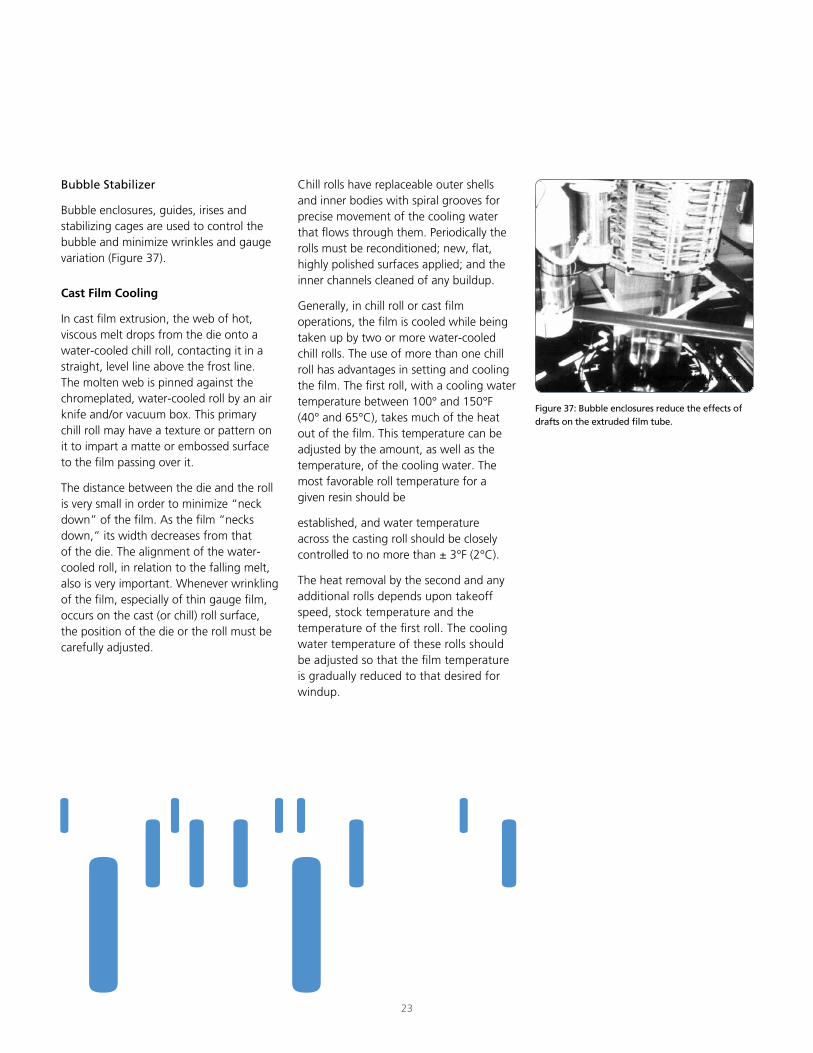
Bubble Stabilizer
Bubble enclosures, guides, irises and stabilizing cages are used to control the bubble and minimize wrinkles and gauge variation (Figure 37).
Cast Film Cooling
In cast film extrusion, the web of hot, viscous melt drops from the die onto a water-cooled chill roll, contacting it in a straight, level line above the frost line. The molten web is pinned against the chromeplated, water-cooled roll by an air knife and/or vacuum box. This primary chill roll may have a texture or pattern on it to impart a matte or embossed surface to the film passing over it.
The distance between the die and the roll is very small in order to minimize “neck down” of the film. As the film “necks down,” its width decreases from that of the die. The alignment of the water-cooled roll, in relation to the falling melt, also is very important. Whenever wrinkling of the film, especially of thin gauge film, occurs on the cast (or chill) roll surface, the position of the die or the roll must be carefully adjusted.
Chill rolls have replaceable outer shells and inner bodies with spiral grooves for precise movement of the cooling water that flows through them. Periodically the rolls must be reconditioned; new, flat, highly polished surfaces applied; and the inner channels cleaned of any buildup.
Generally, in chill roll or cast film operations, the film is cooled while being taken up by two or more water-cooled chill rolls. The use of more than one chill roll has advantages in setting and cooling the film. The first roll, with a cooling water temperature between 100° and 150°F (40° and 65°C), takes much of the heat out of the film. This temperature can be adjusted by the amount, as well as the temperature, of the cooling water. The most favorable roll temperature for a given resin should be
established, and water temperature across the casting roll should be closely controlled to no more than ± 3°F (2°C).
The heat removal by the second and any additional rolls depends upon takeoff speed, stock temperature and the temperature of the first roll. The cooling water temperature of these rolls should be adjusted so that the film temperature is gradually reduced to that desired for windup.
Figure 37: Bubble enclosures reduce the effects of drafts on the extruded film tube.
Courtesy of W & H Corp.
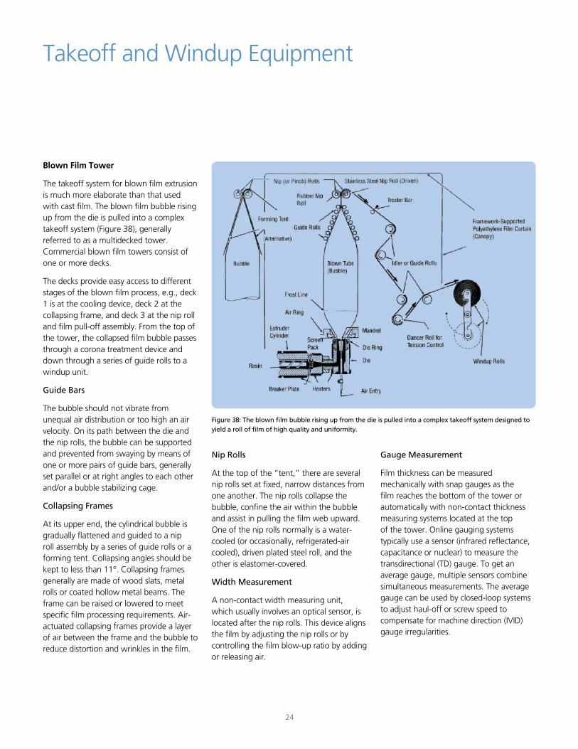
Blown Film Tower
The takeoff system for blown film extrusion is much more elaborate than that used with cast film. The blown film bubble rising up from the die is pulled into a complex takeoff system (Figure 38), generally referred to as a multidecked tower. Commercial blown film towers consist of one or more decks.
The decks provide easy access to different stages of the blown film process, e.g., deck 1 is at the cooling device, deck 2 at the collapsing frame, and deck 3 at the nip roll and film pull-off assembly. From the top of the tower, the collapsed film bubble passes through a corona treatment device and down through a series of guide rolls to a windup unit.
Guide Bars
The bubble should not vibrate from unequal air distribution or too high an air velocity. On its path between the die and the nip rolls, the bubble can be supported and prevented from swaying by means of one or more pairs of guide bars, generally set parallel or at right angles to each other and/or a bubble stabilizing cage.
Collapsing Frames
At its upper end, the cylindrical bubble is gradually flattened and guided to a nip roll assembly by a series of guide rolls or a forming tent. Collapsing angles should be kept to less than 11°. Collapsing frames generally are made of wood slats, metal rolls or coated hollow metal beams. The frame can be raised or lowered to meet specific film processing requirements. Air-actuated collapsing frames provide a layer of air between the frame and the bubble to reduce distortion and wrinkles in the film.
Takeoff and Windup Equipment
Figure 38: The blown film bubble rising up from the die is pulled into a complex takeoff system designed to yield a roll of film of high quality and uniformity.
Nip Rolls
At the top of the “tent,” there are several nip rolls set at fixed, narrow distances from one another. The nip rolls collapse the bubble, confine the air within the bubble and assist in pulling the film web upward. One of the nip rolls normally is a water-cooled (or occasionally, refrigerated-air cooled), driven plated steel roll, and the other is elastomer-covered.
Width Measurement
A non-contact width measuring unit, which usually involves an optical sensor, is located after the nip rolls. This device aligns the film by adjusting the nip rolls or by controlling the film blow-up ratio by adding or releasing air.
Gauge Measurement
Film thickness can be measured mechanically with snap gauges as the film reaches the bottom of the tower or automatically with non-contact thickness measuring systems located at the top of the tower. Online gauging systems typically use a sensor (infrared reflectance, capacitance or nuclear) to measure the transdirectional (TD) gauge. To get an average gauge, multiple sensors combine simultaneous measurements. The average gauge can be used by closed-loop systems to adjust haul-off or screw speed to compensate for machine direction (IVID) gauge irregularities.
24
25
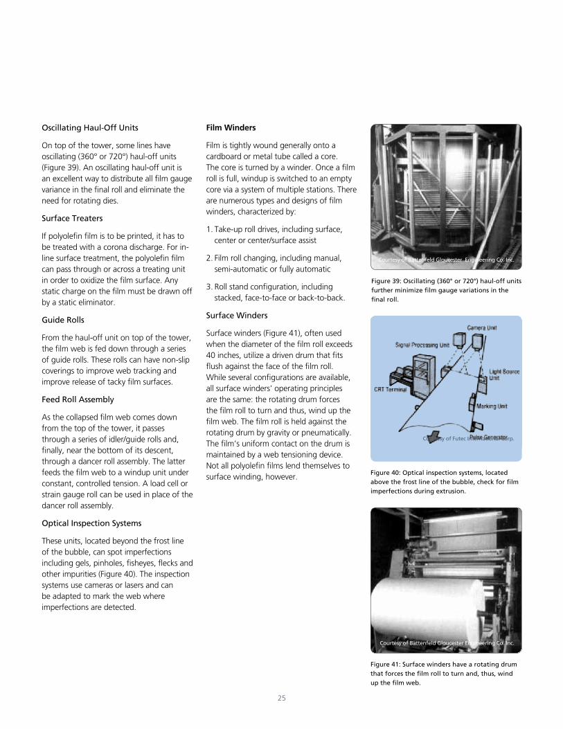
Oscillating Haul-Off Units
On top of the tower, some lines have oscillating (360° or 720°) haul-off units (Figure 39). An oscillating haul-off unit is an excellent way to distribute all film gauge variance in the final roll and eliminate the need for rotating dies.
Surface Treaters
If polyolefin film is to be printed, it has to be treated with a corona discharge. For in-line surface treatment, the polyolefin film can pass through or across a treating unit in order to oxidize the film surface. Any static charge on the film must be drawn off by a static eliminator.
Guide Rolls
From the haul-off unit on top of the tower, the film web is fed down through a series of guide rolls. These rolls can have non-slip coverings to improve web tracking and improve release of tacky film surfaces.
Feed Roll Assembly
As the collapsed film web comes down from the top of the tower, it passes through a series of idler/guide rolls and, finally, near the bottom of its descent, through a dancer roll assembly. The latter feeds the film web to a windup unit under constant, controlled tension. A load cell or strain gauge roll can be used in place of the dancer roll assembly.
Optical Inspection Systems
These units, located beyond the frost line of the bubble, can spot imperfections including gels, pinholes, fisheyes, flecks and other impurities (Figure 40). The inspection systems use cameras or lasers and can be adapted to mark the web where imperfections are detected.
Film Winders
Film is tightly wound generally onto a cardboard or metal tube called a core. The core is turned by a winder. Once a film roll is full, windup is switched to an empty core via a system of multiple stations. There are numerous types and designs of film winders, characterized by:
1. Take-up roll drives, including surface, center or center/surface assist
2. Film roll changing, including manual, semi-automatic or fully automatic
3. Roll stand configuration, including stacked, face-to-face or back-to-back.
Surface Winders
Surface winders (Figure 41), often used when the diameter of the film roll exceeds 40 inches, utilize a driven drum that fits flush against the face of the film roll. While several configurations are available, all surface winders’ operating principles are the same: the rotating drum forces the film roll to turn and thus, wind up the film web. The film roll is held against the rotating drum by gravity or pneumatically. The film’s uniform contact on the drum is maintained by a web tensioning device. Not all polyolefin films lend themselves to surface winding, however.
Figure 39: Oscillating (360° or 720°) haul-off units further minimize film gauge variations in the final roll.
Figure 40: Optical inspection systems, located above the frost line of the bubble, check for film imperfections during extrusion.
Figure 41: Surface winders have a rotating drum that forces the film roll to turn and, thus, wind up the film web.
Courtesy of Battenfeld Gloucester Engineering Co. Inc.
Courtesy of Futec International Corp.
Courtesy of Battenfeld Gloucester Engineering Co. Inc.
26
Center Winders
With center winders, torque is applied directly to the roll shaft. To form film rolls on cores under constant tension, a center winder must slow down at a rate inversely proportional to the film roll’s constantly increasing diameter. The cores onto which the film winds are held by chucks inserted in both ends.
Center winders do not rely on the layon rolls to force air out from under the web or to ensure optimum flat contact. Some center winders run shaftless (film is wound directly on the core) although most commercial film lines will include air shafts to inflate rubber bladders in expandable metal shafts that fit inside the cardboard cores. These air-supported shafts permit different core diameters to be used and enables the core to resist the pressure of the film winding. The latter benefit is particularly important when separate film widths are wound on a common core, i.e., there is no overlapping. A lay-on roll often is part of an assembly that also includes a pneumatically actuated slitting knife for cutting the web into two or more narrower webs. A bowed or spreader roll also may be part of the assembly to slightly separate the several slit webs.
Surface/Center Assist Winders
Surface/center assist winders have center drives added to the shaft of a surface winder. This type of winder separates winding tension from web positioning requirements and roll hardness.
Gap Winding
A modification of the center winding technique is gap or proximity winding. A gap of about ¼ inch is maintained between the surface roll and the film roll and there is a tension controlled drive for each roll. The film roll is gradually moved away as film builds up on it. Gap winding, with its air layer between film layers, is particularly effective for tacky polyolefin films, e.g., stretch wrap. Taper Tensioning
When the diameter of the final film roll is greater than six times the diameter of the core (called the build-up ratio), it generally is recommended to gradually reduce web tension or to use taper tensioning. This can be done by controlling the dancer roll assembly or the strain gauge roll. For extensible or soft polyolefin films, taper tensioning eliminates roll defects such as crowning and\or wrinkling.
Automatic Roll Changers
Automatic roll changers deflate air shafts, remove the full roll, place the roll on a cart or the floor, install empty cores into the ready position and inflate the shafts, all automatically. They are particularly useful for stretch-film winding and other high-speed applications that require relatively small roll diameters.
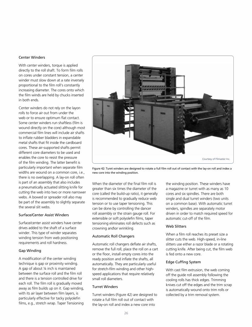
Turret Winders
Turret winders (Figure 42) are designed to rotate a full film roll out of contact with the lay-on roll and index a new core into
Figure 42: Turet winders are designed to rotate a full film roll out of contact with the lay-on roll and index a new core into the winding position.
the winding position. These winders have a magazine or turret with as many as 10 cores and six spindles. There are both single and dual turret winders (two units on a common base). With automatic turret winders, spindles are separately motor driven in order to match required speed for automatic cut-off of the film.
Web Slitters
When a film roll reaches its preset size a slitter cuts the web. High-speed, in-line slitters use either a razor blade or a rotating cutting knife. After being cut, the film web is fed onto a new core.
Edge Cuffing System
With cast film extrusion, the web coming off the guide roll assembly following the cooling rolls has thick edges. Trimming knives cut off the edges and the trim scrap is automatically wound onto trim rolls or collected by a trim removal system.
Courtesy of Filmaster Inc.
27
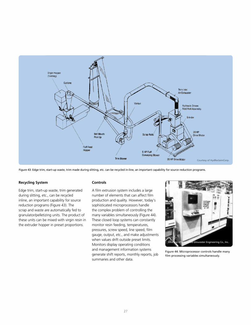
Recycling System
Edge trim, start-up waste, trim generated during slitting, etc., can be recycled inline, an important capability for source reduction programs (Figure 43). The scrap and waste are automatically fed to granulator/pelletizing units. The product of these units can be mixed with virgin resin in the extruder hopper in preset proportions.
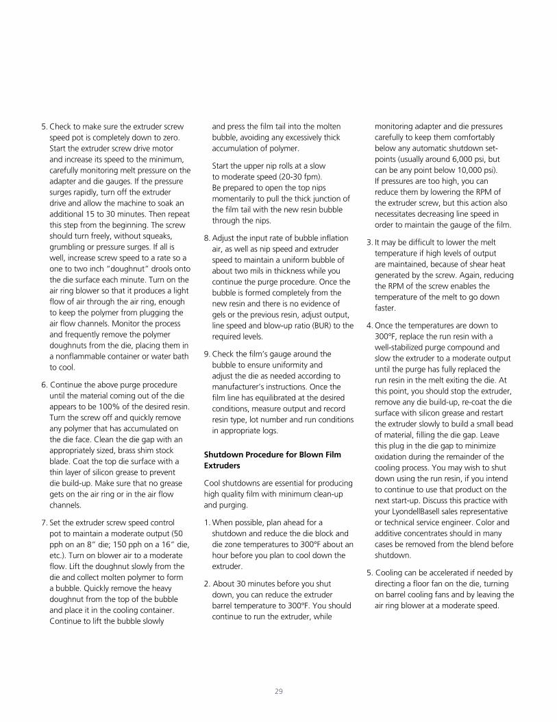
Controls
A film extrusion system includes a large number of elements that can affect film production and quality. However, today’s sophisticated microprocessors handle the complex problem of controlling the many variables simultaneously (Figure 44). These closed loop systems can constantly monitor resin feeding, temperatures, pressures, screw speed, line speed, film gauge, output, etc., and make adjustments when values drift outside preset limits. Monitors display operating conditions and management information systems generate shift reports, monthly reports, job summaries and other data.
Figure 43: Edge trim, start-up waste, trim made during slitting, etc. can be recycled in-line, an important capability for source reduction programs.
Courtesy of HydReclaimCorp.
Figure 44: Microprocessor controls handle many film processing variables simultaneously.
Courtesy of Battenfeld Gloucester Engineering Co., Inc..
28
Start-Up of a Blown Film Line
Quality film production starts before the extruder is turned on. The first step is a thorough examination of all components of the extrusion line. Starting at the hopper and proceeding all the way to the take-up unit, make sure that all the components are clean. In particular, the die must be clean and free from nicks, scratches or other deformities.
The die must be levelled in all directions after the adapter has been tightly bolted to the extruder barrel head. The nip rolls also must be level. The die must be plumbed from the center of the nip rolls for vertical centering.
Accident Prevention
The conditions at each film extrusion plant are unique to that shop. Therefore, each processor must be aware of the properties of polyolefin resins as detailed in the Materials Safety Data Sheets (MSDS) available from resin suppliers and the potential mechanical hazards posed by the equipment being used to extrude and wind up the film. A comprehensive accident prevention program developed for a film extrusion shop should include, but not be limited to the following considerations:
• Combustibility of polyolefin resins
• Decomposition products
• Personal protection equipment, including eye and face protection, respiratory protection and protective clothing
Operation of a Blown Film Line
• Emergency shutdown procedures
• Lock-out procedures
• Line breaking procedures
• Lifting procedures
• Use of knives for cutting film webs
• General housekeeping
• Adequate clearances and accessability
• Ventilation
Prior to starting up the extruder, be sure to have the following items available:
• Safety glasses for all those assisting in the start-up Loose fitting, heavy duty work gloves
• A large metal container for collecting melt produced during the start-up procedure
• Soft metal tools for use in removing any hardened plastic from the die area
• A sharp knife for use in cutting film on the windup rolls
• Check emergency stops and instrumentation
Many different extruders are used to produce film from polyolefins. Therefore, the following procedures for start-up and shutdown are provided only as a general guide. The operating manual for the specific extruder being used should be closely followed.
1. Prior to start-up, check to see that all safety devices are in place and operational. Walk around the machine to be certain that there are no obstructions to the machine’s movement and that nobody is working too closely to the line.
2. The first step in starting up a blown film line is to heat the equipment. It is advisable to turn on the die heaters first and allow them to heat 30 to 60 minutes before turning on the barrel heaters. During the warm-up period, a temperature setting of 300°F/ 150°C is adequate for most polyolefin resins and minimizes degradation of the stagnant polymer.
Once both the die and barrel heating zones have reached 300°F, set the required processing temperatures for each of the heating zones. It is desirable to let the machine continue to “soak” an additional 30 to 60 minutes to equilibrate in temperature.
3. Determine whether the desired purge compound or resin is in the feed hopper. If necessary, empty the hopper and remove, clean and replace the hopper magnets. Refill the hopper with the appropriate resin. This is also a good time to locate insulated gloves for handling hot polymer and cleaning tools, such as brass putty knives, brass shim stock, copper gauze and silicon grease.
4. Thread film through the winder, tower idler rolls and nip rolls according to the manufacturer’s recommendations. Bring a sturdy film tail back through the system to nearly reach the floor in the die area.
29
5. Check to make sure the extruder screw speed pot is completely down to zero. Start the extruder screw drive motor and increase its speed to the minimum, carefully monitoring melt pressure on the adapter and die gauges. If the pressure surges rapidly, turn off the extruder drive and allow the machine to soak an additional 15 to 30 minutes. Then repeat this step from the beginning. The screw should turn freely, without squeaks, grumbling or pressure surges. If all is well, increase screw speed to a rate so a one to two inch “doughnut” drools onto the die surface each minute. Turn on the air ring blower so that it produces a light flow of air through the air ring, enough to keep the polymer from plugging the air flow channels. Monitor the process and frequently remove the polymer doughnuts from the die, placing them in a nonflammable container or water bath to cool.
6. Continue the above purge procedure until the material coming out of the die appears to be 100% of the desired resin. Turn the screw off and quickly remove any polymer that has accumulated on the die face. Clean the die gap with an appropriately sized, brass shim stock blade. Coat the top die surface with a thin layer of silicon grease to prevent die build-up. Make sure that no grease gets on the air ring or in the air flow channels.
7. Set the extruder screw speed control pot to maintain a moderate output (50 pph on an 8” die; 150 pph on a 16” die, etc.). Turn on blower air to a moderate flow. Lift the doughnut slowly from the die and collect molten polymer to form a bubble. Quickly remove the heavy doughnut from the top of the bubble and place it in the cooling container. Continue to lift the bubble slowly
and press the film tail into the molten bubble, avoiding any excessively thick accumulation of polymer.
Start the upper nip rolls at a slow to moderate speed (20-30 fpm). Be prepared to open the top nips momentarily to pull the thick junction of the film tail with the new resin bubble through the nips.
8. Adjust the input rate of bubble inflation air, as well as nip speed and extruder speed to maintain a uniform bubble of about two mils in thickness while you continue the purge procedure. Once the bubble is formed completely from the new resin and there is no evidence of gels or the previous resin, adjust output, line speed and blow-up ratio (BUR) to the required levels.
9. Check the film’s gauge around the bubble to ensure uniformity and adjust the die as needed according to manufacturer’s instructions. Once the film line has equilibrated at the desired conditions, measure output and record resin type, lot number and run conditions in appropriate logs.
Shutdown Procedure for Blown Film Extruders
Cool shutdowns are essential for producing high quality film with minimum clean-up and purging.
1. When possible, plan ahead for a shutdown and reduce the die block and die zone temperatures to 300°F about an hour before you plan to cool down the extruder.
2. About 30 minutes before you shut down, you can reduce the extruder barrel temperature to 300°F. You should continue to run the extruder, while
monitoring adapter and die pressures carefully to keep them comfortably below any automatic shutdown set-points (usually around 6,000 psi, but can be any point below 10,000 psi). If pressures are too high, you can reduce them by lowering the RPM of the extruder screw, but this action also necessitates decreasing line speed in order to maintain the gauge of the film.
3. It may be difficult to lower the melt temperature if high levels of output are maintained, because of shear heat generated by the screw. Again, reducing the RPM of the screw enables the temperature of the melt to go down faster.
4. Once the temperatures are down to 300°F, replace the run resin with a well-stabilized purge compound and slow the extruder to a moderate output until the purge has fully replaced the run resin in the melt exiting the die. At this point, you should stop the extruder, remove any die build-up, re-coat the die surface with silicon grease and restart the extruder slowly to build a small bead of material, filling the die gap. Leave this plug in the die gap to minimize oxidation during the remainder of the cooling process. You may wish to shut down using the run resin, if you intend to continue to use that product on the next start-up. Discuss this practice with your LyondellBasell sales representative or technical service engineer. Color and additive concentrates should in many cases be removed from the blend before shutdown.
5. Cooling can be accelerated if needed by directing a floor fan on the die, turning on barrel cooling fans and by leaving the air ring blower at a moderate speed.
30
Over long periods of continuous operation, a layer of oxidized polymer slowly builds up on a polyolefin film extruder, particularly on the inside barrel walls and the screw. Eventually, this degraded resin will begin to flake off. This, in turn, will result in film defects such as gels or yellow-brown oxidized particles. Such defects cause the film to have a poor appearance and, especially in very thin film, can actually cause holes or tearoff of the film as it comes out of the extrusion die.
The inside surface of the die and especially the lands must be kept well polished. The slightest surface irregularities will result in gauge variations and die lines (lengthwise parallel grooves). Occasionally, die lines may be caused by decomposed resin caught inside the die, sometimes because the inside of the die surface is poorly designed. If their size indicates that these die lines are caused by small pieces of decomposed resin, a brass shim should be run through the die opening to remove the particles. If bigger pieces appear to be the cause, the die must be cleaned. A definite periodic cleaning schedule should be established. The time interval between thorough cleanings can best be determined by experience. If the extruder is continuously in use over long periods, cleaning may be needed every two months, although this can be extended by using purge compounds and careful startup and shutdown procedures.
Cleaning The Extruder and Its Parts
How To Clean The Extruder
The following disassembly steps are recommended prior to cleaning the extruder:
1. Let the extruder run with resin, without further feeding, until the screw can be seen when the hopper is uncovered. Do not let the screw run “dry.”
2. Turn off all electricity and water.
3. For a blown film line, remove the air ring while the machine is still hot; for a cast film line, push away the windup equipment and remove anything else in line with the screw while the machine is still hot.
4. Disconnect electrical and water lines.
5. Remove the die. If it is a blown film die, loosen the hinged collar first. To remove a die, use heavy-duty carrying equipment (overhead crane or forklift truck).
6. Remove the barrel cover and the adapter from the barrel.
7. Remove the breaker plate with the screens from the adapter.
8. Push the screw forward with a rod from the back end of the barrel and remove it. Now, you have access to all the extruder parts to be cleaned or exchanged.
To clean the screw, first use a copperor brass-bladed knife (putty knife) to remove most of the molten resin adhering to the screw. Do not use a steel blade. Next, clean the screw with copper or brass wool. Use a silicone grease spray to help remove tightly adhering resin. Finally, coat the screw with a thin layer of silicone grease.
To clean the barrel, run a brass brush at the end of a long handle through the barrel to remove any resin build up. Use a similar tool for lubrication with silicone grease.
To clean the adapter, also use copper or brass tools. Then lubricate with silicone grease. Clean the collar. Clean and lubricate the seat of the adapter. The face of both the adapter and the barrel will be clean and need no further treatment if they were fitted accurately during the previous run.
To clean the breaker plate, burn away any oxidized polymer clinging to, and possibly clogging it. This can be done using a propane torch. First clean one side and then the other. To prevent molten resin from dripping into the torch, hold it so that the flame hits the plate horizontally. Specially designed cleaning ovens also may be used for breaker plates or small parts.
To clean the blown film die, first pull out the mandrel, or die pin. Manually remove most of the resin build-up. Silicone grease and a brass or wooden “knife” will help in removing stubborn resin. Next, use a brass- or copper-wool cloth or brush to finish the cleaning. Finally, use silicone grease for lubrication.
To clean the cast film die, first disassemble it as much as possible. Use only copper or brass tools for cleaning all the parts. Scrape the manifold, the lands and the fixed and adjustable jaws free of the bulk of resin build-up with a brass or wooden “knife.” Then finish the cleaning job with a copper-wool cloth or brush. Polish the curved surfaces of the manifold with a very fine grit polishing cloth, and hone its flat surface to remove any mars or scratches.
As has been emphasized several times in the preceding section on extruder startup procedures, cleanliness is extremely important to producing quality polyolefin film.
31
Cast or Flat Film Forming
The following are some suggestions on processing conditions that may improve cast film properties:
Temperatures
Barrel temperatures in cast or flat film extrusion are generally higher than for tubular (blown) film extrusion: between 280° and 375°F (140° and 190°C) just in front of the hopper to about 555°F (290°C) at the die lands (melt temperature). It is important to keep melt temperatures uniform across the die width. Each heating zone should not vary by more than 2°F (11°C).
Screw speed
In flat film extrusion, screw speed controls output more than any other machine factor. For efficient flat film machine operation and comparatively high output from a given machine, the screw should be run as fast as possible without pressure, temperature or gauge fluctuations, or any specks or “applesauce” appearing in the film. If output is unsatisfactory under these conditions, an improved screw design may be needed.
Gauge Control
There is no close relationship between die opening and film gauge in flat film forming. Higher gauges generally require large openings. For 1 to 3 mil (25 to 75 micron) film, the die opening is normally around 20 mils (0.5mm).
Width
When the hot film is drawn down onto the cooled first chill roll, it may “neck-in” (shrink) at the edges. Neck-in is the difference between the hot melt width at the die lips and the film width on the
Optimizing The Film Extrusion Process
chill roll. When there is much neck-in, “beading” takes place. This is a thickening at both edges of the film. When film with beading is wound up, the roll will sag in the middle, making it difficult to use later for packaging or bag making. In these cases, the film must be trimmed at both edges.
The smaller the distance between the die and the chill roll and the narrower the die opening, the less the neck-in with cast film making. Neck-in will not occur in blown film making since the bubble has no edges which may shrink.
Another cast film defect related to cooling is “puckering,” a slight bulging across the film recurring at regular intervals. Puckering can be reduced by increasing the temperature of the first chill roll.
Cooling
In flat film casting, the film frost line appears on the first chill roll. It should appear as a level, straight line. An uneven frost line indicates non-uniform cooling or uneven film gauge on the chill roll. This can cause the film to warp and wrinkle on the windup roll. Most often, the cause of an uneven frost line is an improper adjustment of the die opening. This may also cause variations in film thickness.
Tubular Film Forming
The following are some suggestions on processing conditions that may improve tubular film properties:
Temperatures
Barrel temperatures in blown film extrusion are generally low, between 280° and 375°F (140° and 190°C) just in front of the hopper to about 430°F (220°C) near the screen pack. Temperature control of each heating zone is very important. A drop or
rise in one zone may indicate a defective heater. A rise may point to a hot spot caused by a damaged screw rubbing on the barrel lining. Regular checks for burned-out or loose heaters is essential to good film production.
In blown film making, the pressure gauges should indicate pressures in the 1,000 to 5,000 psi (70 to 350 kg/cm²) range. In cast film making, the pressures should be 1,000 to 2,500 psi (70 to 175 kg/ cm²).
For best film properties, use the highest extrusion temperature which still permits adequate film cooling and good windup, as well as the maintenance of a uniform bubble or flat film web.
Screw Speed
While the extruder is running, the hopper should be kept well filled with resin. Screw speed, measured in revolutions per minute (rpm), varies greatly depending upon the type of polyolefin being extruded and whether blown or flat film is being made.
Generally, the higher the screw speed, the higher the output and the higher the amount of internal heat created. More internal heat means that less external heating is needed. Very high screw speeds can result in extreme temperature fluctuations and “applesauce,” even with a heavy screen pack and a long screw. Temperature and pressure fluctuations usually are the first indication that screw speed is too high or design of the screw is not appropriate.
Blow-Up Ratio
Bubble diameter is almost always greater than the die diameter. The former divided by the latter is called the blow-up ratio (BUR). The bubble diameter must not be confused with the width of the flattened double layer of film between the nip rolls or on the windup roll. The width of this double film layer is 1.57 times the bubble diameter. The formulas,
Film lay flat width = 1.57 x die diameter x BUR
BUR = 0.637 x (blown film width/die diameter)
can be used to figure the width of the lay flat film on the windup roll or the BUR, if either of them and the die diameter are known. A larger BUR over a given die will result in thinner gauge film and greater film width at constant output (screw rpm) and take off.
Cooling
Generally, it is quite easy to see on a blown film bubble where the melt coming out of the die changes from a viscous fluid to solid form. The area of change is called the “frost line” because here the cooling film first appears “frosty.” With some types of polyolefins however, the frost line may not be visible.
For practical purposes, the frost line in blown film can be defined as that line around the film where the final tube diameter is reached. If visible, the frost line should be a level, ring-shaped zone around the bubble.
The primary cause for a non-uniform frost line can be improper adjustment of the die opening. This may cause variations in film thickness and, thereby, nonuniform film cooling and an uneven frost line. An
uneven frost line also may be caused by non-uniform cooling around the air ring.
Raising the frost line gives the film more time to solidity. This results in a smoother surface and thus, higher clarity and gloss. The frost line height is also essential in controlling some physical properties of the film, such as tear strength, tensile strength and impact strength.
However, too high a frost line may cause the film to block (stick) when rolled up, to stick to the nip rolls and to lead to problems in film gauge control. The latter two are minimized somewhat it refrigerated air is used to cool the nip rolls and it these rolls are located high above the extruder.
Thus, the height of the frost line above the die in blown film extrusion is particularly important. Increasing with the tube diameter, it may vary between 4 and 24 inches (10 and 61 cm) above the die face for tubing up to 3 feet (91 cm) in diameter. The recommended range is 8 to 19 inches (20 to 48 cm) above the die.
The height of the frost line changes as extruder output, take off speed, in chill roll casting or the volume of cooling air blown against the bubble changes. When the screw speed goes up, the distance between the die and the frost line is increased. When more cooling air is blown against the bubble, the frost line drops.
However, if the frost line height needs to be adjusted purposefully to change the properties mentioned earlier, alter the cooling air volume. Controlling the quantity and direction of this air is important because both are essential in film gauge control. Non-uniform gauge is often caused by an uneven flow of cooling air from the air ring around the blown tube.
32
33
Barrier
Thickness uniformity is the most important processing factor affecting barrier properties. With very thin film, blemishes and imperfections (fisheyes, etc.) will reduce barrier properties. Further, some additives and colorants also can reduce a film’s abilty to provide a barrier to moisture, etc.
Clarity
Film clarity improves with increasing processing temperatures and faster film cooling. However, if air velocity is too high, the bubble may chatter and clarity will be affected. Antiblocking agents also can reduce film clarity.
Environmental Stress Crack Resistance
Other than minimizing the heat history of the resin i.e., reducing the amount of regrind mixed with virgin resin, there is little that can be done via processing variables to improve ESCR. Resin choice is the most important factor.
Gauge Uniformity
The problem of poor gauge uniformity in blown film is quite common. If variation in gauge around the circumference of extruded film is less than ±10%, there is no problem. If it exceeds this level, corrective steps should be taken because film of uniform gauge looks better and has generally superior physical properties.
Heavier gauge areas on one side of a film appear as humps on a roll that not only impair film appearance, but may actually stretch it in the area of the hump. Film thus “deformed” may be difficult to handle on packaging equipment and to heat seal.
Process Variables Controlling PropertyImprovement
Poor bubble stability, film wrinkling and take off problems are early indicators of uneven gauge. With thin films, uneven gauge results in tears and snap-offs. Gusseting also is harder to control when gauge variations are excessive.
Non-uniform melt temperature may result in non-uniform film gauge and other defects. Overheated melt may come out of the die too fluid and the resultant film may be difficult to cool and wind up.
Poor mixing may also result in nonuniform film thickness. Film of nonuniform gauge, in turn, results in unevenly wound film rolls, as well as in weak sections wherever the film is thinner than specified. Film thicker than specified is, of course, a waste of resin. It is, therefore, essential to periodically measure the gauge on a cut piece of film or install a built-in electronic gauge-measuring and recording device.
Gloss
Film gloss improves with increasing operating temperatures and a rise in the frost line. As with clarity, antiblocking agents can reduce film gloss.
Heat Sealability
Operating the film line at too high a temperature can result in oxidation which will reduce film heat sealability as will some additives, such as antistat, slip and dispersion agents.
Stiffness
Blown film is stiffer than cast film for any given resin. The main factor affecting stiffness, however, is the resin choice: higher density resins yield stiffer films. BUR has only minimal effect of a film’s stiffness.
Strength
As with stiffness, the most important factor controlling strength is the choice of resin. BUR has only minimal effect of a film’s strength. Strength can also be improved by using less regrind in the resin stream.
Toughness
Film toughness generally is best with resins that are more difficult to process, i.e., the low MI, high molecular weight grades. Balancing orientation (MD vs. TD) is very important to film toughness: too much orientation in one direction can result in splitting under stress.
Slip
Film surface and additive packages are the keys to slip performance. Higher gloss film also has a higher coefficient of friction. Therefore, lower stock temperatures may give the film better slip properties, as will lowering the frost line.
Shrink Wrap and Stretch Wrap
For two-directional shrink wrap, the most important process variable is a balanced BUR. Minimizing film imperfections is the most important processing factor affecting stretch wrap: “gels don’t stretch.” LLDPE resins are the main grades used for stretch wrap. For stretch wrapping of pallets, coextruded films can be produced that will have high cling on the surface in contact with the product packaged and an outer surface with high slip (low coefficient of friction). Tackifiers may also be added to increase cling.
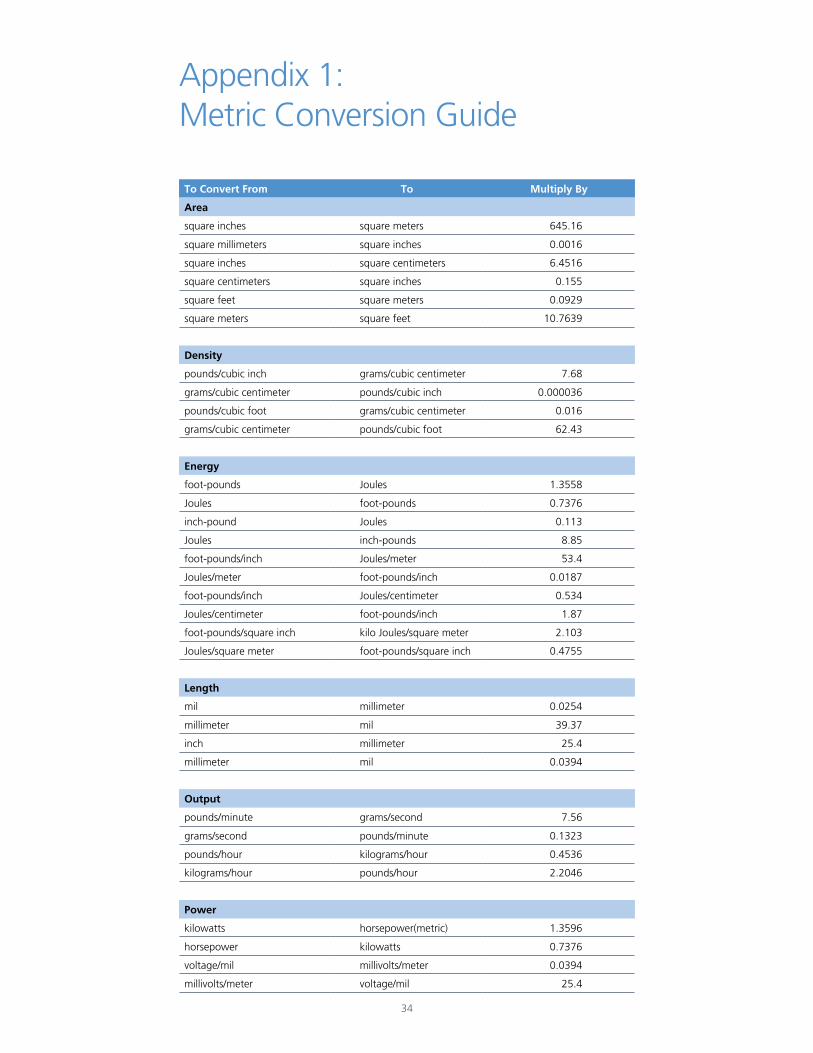
To Convert From To Multiply By
Area
square inches square meters 645.16
square millimeters square inches 0.0016
square inches square centimeters 6.4516
square centimeters square inches 0.155
square feet square meters 0.0929
square meters square feet 10.7639
Density
pounds/cubic inch grams/cubic centimeter 7.68
grams/cubic centimeter pounds/cubic inch 0.000036
pounds/cubic foot grams/cubic centimeter 0.016
grams/cubic centimeter pounds/cubic foot 62.43
Energy
foot-pounds Joules 1.3558
Joules foot-pounds 0.7376
inch-pound Joules 0.113
Joules inch-pounds 8.85
foot-pounds/inch Joules/meter 53.4
Joules/meter foot-pounds/inch 0.0187
foot-pounds/inch Joules/centimeter 0.534
Joules/centimeter foot-pounds/inch 1.87
foot-pounds/square inch kilo Joules/square meter 2.103
Joules/square meter foot-pounds/square inch 0.4755
Length
mil millimeter 0.0254
millimeter mil 39.37
inch millimeter 25.4
millimeter mil 0.0394
Output
pounds/minute grams/second 7.56
grams/second pounds/minute 0.1323
pounds/hour kilograms/hour 0.4536
kilograms/hour pounds/hour 2.2046
Power
kilowatts horsepower(metric) 1.3596
horsepower kilowatts 0.7376
voltage/mil millivolts/meter 0.0394
millivolts/meter voltage/mil 25.4
Appendix 1: Metric Conversion Guide
34
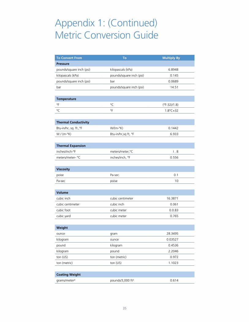
To Convert From To Multiply By
Pressure
pounds/square inch (psi) kilopascals (kPa) 6.8948
kilopascals (kPa) pounds/square inch (psi) 0.145
pounds/square inch (psi) bar 0.0689
bar pounds/square inch (psi) 14.51
Temperature
°F °C (°F-32)/1.8)
°C °F 1.8°C+32
Thermal Conductivity
Btu-in/hr, sq. ft.,°F W/(m-°K) 0.1442
W / (m-°K) Btu-in/hr,sq ft, °F 6.933
Thermal Expansion
inches/inch-°F meters/meter,°C I . 8
meters/meter- °C inches/inch, °F 0.556
Viscosity
poise Pa-sec. 0.1
Pa-sec poise 10
Volume
cubic inch cubic centimeter 16.3871
cubic centimeter cubic inch 0.061
cubic foot cubic meter 0.0.83
cubic yard cubic meter 0.765
Weight
ounce gram 28.3495
kilogram ounce 0.03527
pound kilogram 0.4536
kilogram pound 2.2046
ton (US) ton (metric) 0.972
ton (metric) ton (US) 1.1023
Coating Weight
grams/meter² pounds/3,000 ft² 0.614
Appendix 1: (Continued) Metric Conversion Guide
35
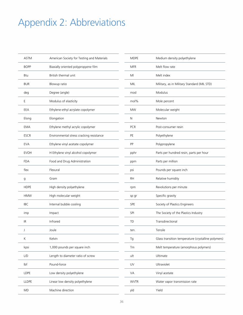
ASTM American Society for Testing and Materials
BOPP Biaxially oriented polypropyene film
Btu British thermal unit
BUR Blowup ratio
deg Degree (angle)
E Modulus of elasticity
EEA Ethylene-ethyl acrylate copolymer
Elong Elongation
EMA Ethylene methyl acrylic copolymer
ESCR Environmental stress cracking resistance
EVA Ethylene vinyl acetate copolymer
EVOH H Ethylene vinyl alcohol copolymer
FDA Food and Drug Administration
flex Flexural
g Gram
HDPE High density polyethylene
HMW High molecular weight
IBC Internal bubble cooling
imp Impact
IR Infrared
J Joule
K Kelvin
kpsi 1,000 pounds per square inch
L/D Length to diameter ratio of screw
lbf Pound-force
LDPE Low density polyethylene
LLDPE Linear low density polyethylene
MD Machine direction
Appendix 2: Abbreviations
36
MDPE Medium density polyethylene
MFR Melt flow rate
Ml Melt index
MIL Military, as in Military Standard (MIL STD)
mod Modulus
mol% Mole percent
MW Molecular weight
N Newton
PCR Post-consumer resin
PE Polyethylene
PP Polypropylene
pphr Parts per hundred resin, parts per hour
ppm Parts per million
psi Pounds per square inch
RH Relative humidity
rpm Revolutions per minute
sp gr Specific gravity
SPE Society of Plastics Engineers
SPI The Society of the Plastics Industry
TD Transdirectional
ten. Tensile
Tg Glass transition temperature (crystalline polymers)
Tm Melt temperature (amorphous polymers)
ult Ultimate
UV Ultraviolet
VA Vinyl acetate
WVTR Water vapor transmission rate
yld Yield
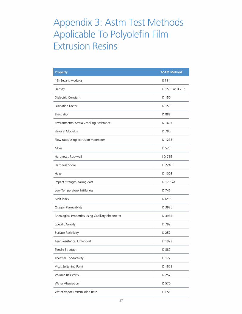
Property ASTM Method
1% Secant Modulus E 111
Density D 1505 or D 792
Dielectric Constant D 150
Disipation Factor D 150
Elongation D 882
Environmental Stress Cracking Resistance D 1693
Flexural Modulus D 790
Flow rates using extrusion rheometer D 1238
Gloss D 523
Hardness , Rockwell l D 785
Hardness Shore D 2240
Haze D 1003
Impact Strength, falling dart D 1709/A
Low Temperature Brittleness D 746
Melt Index D1238
Oxygen Permeability D 3985
Rheological Properties Using Capillary Rheometer D 3985
Specific Gravity D 792
Surface Resistivity D 257
Tear Resistance, Elmendorf D 1922
Tensile Strength D 882
Thermal Conductivity C 177
Vicat Softening Point D 1525
Volume Resistivity D 257
Water Absorption D 570
Water Vapor Transmission Rate F 372
Appendix 3: Astm Test Methods Applicable To Polyolefin Film Extrusion Resins
37
Alathon® HDPE Polyethylene Resins
Aquathene® Ethylene vinylsilane compounds for wire and cable
Flexathene® Thermoplastic Polyolefin Resins
Integrate™ Functionalized Polyolefins
Microthene® Powdered polyethylene resins
Petrothene® Polyethylene and polypropylene resins
Plexar® Tie-layer resins
Ultrathene® Ethylene vinly acetate (EVA) copolymer resins
Appendix 4: Trade Names for Products of LyondellBasell Chemicals
38
Houston, TX LyondellBasell Tower, Suite 700 1221 McKinney Street Houston, TX 77010 P.O. Box 3646 (77253-3646) Tel: +1 713 309 7200
Cincinnati, OH Cincinnati Technology Center 11530 Northlake Drive Cincinnati, OH 45249 Tel: +1 513 530 4000
lyb.com
6047/1004
Before using a product sold by a company of the LyondellBasell family of companies, users should make their own independent determination that the product is suitable for the intended use and can be used safely and legally. SELLER MAKES NO WARRANTY; EXPRESS OR IMPLIED (INCLUDING ANY WARRANTY OF MERCHANTABILITY OR FITNESS FOR A PARTICULAR PURPOSE OR ANY WARRANTY) OTHER THAN AS SEPARATELY AGREED TO BY THE PARTIES IN A CONTRACT.
LyondellBasell prohibits or restricts the use of its products in certain applications. For further information on restrictions or prohibitions of use, please contact a LyondellBasell representative.
Users should review the applicable Safety Data Sheet before handling the product.
Adex, Adstif, Adsyl, Akoaoor, Akoalit, Alathon, Alkylate, Amazing Chemistry, Aquamarine, Aquathene, Arcopure, Arctic Plus, Arctic Shield, Avant, Catalloy, Clyrell, CRP, Crystex, Dexex, Duopac, Duoprime, Explore & Experiment, Filmex, Flexathene, Glacido, Hifax, Hiex, Histif, Hostacom, Hostalen, Ideal, Integrate, Koattro, LIPP, Lucalen, Luexen, Lupolen, Lupolex, Luposim, Lupostress, Lupotech, Metocene, Microthene, Moplen, MPDIOL, Nerolex, Nexprene, Petrothene, Plexar, Polymeg, Pristene, Prodex, Pro-Fax, Punctilious, Purell, SAA100, SAA101, Sequel, Softell, Spherilene, Spheripol, Spherizone, Starex, Stretchene, Superex, TBAc , Tebol, T-Hydro, Toppyl, Trans4m, Tuo, Ultrathene, Vacido and Valtec are trademarks owned or used by the LyondellBasell family of companies.
Adsyl, Akoaoor, Akoalit, Alathon, Aquamarine, Arcopure, Arctic Plus, Arctic Shield, Avant, CRP, Crystex, Dexex, Duopac, Duoprime, Explore & Experiment, Filmex, Flexathene, Hifax, Hostacom, Hostalen, Ideal, Integrate, Koattro, Lucalen, Lupolen, Metocene, Microthene, Moplen, MPDIOL, Nexprene, Petrothene, Plexar, Polymeg, Pristene, Pro-Fax, Punctilious, Purell, Sequel, Softell, Spheripol, Spherizone, Starex, Tebol, T-Hydro, Toppyl, Tuo and Ultrathene are registered in the U.S. Patent and Trademark Office.