a guide to s indicated in a number of nace · copper/copper sulfate (cu/cuso 4) electrodes (cses)...
TRANSCRIPT

32 MATERIALS PERFORMANCE September 2009
A Guide to Understanding
Reference Electrode Readings
RobeRt M. PaRk, M.C. Miller Co., Inc., Sebastian, Florida
Reference electrodes are essential to evaluate
corrosion and cathodic protection on buried and
submerged structures. This article discusses the
nature of structure-to-electrolyte readings employing
copper/copper sulfate (Cu/CuSO4) electrodes (CSEs)
and various other “acceptable” reference electrode
types. A universal formula is presented that allows
readings taken with non-CSE reference electrodes to
be adjusted to the CSE potential.
As indicated in a number of NACE International standards, includ-ing SP0169-2007,1 the critical decision as to whether or not a
buried or submerged metallic structure is cathodically protected (polarized) to a sufficient degree is based on a measure-ment of the metal’s polarized potential, in its environment (soil, seawater, etc.), relative to the potential of a reference electrode. Consequently, no equipment item is of more fundamental importance to the cathodic protection (CP) industry than the reference electrode.
There are a number of different refer-ence electrode types available, including those that are identified in SP0169-2007, that are acceptable alternatives to the copper/copper sulfate (Cu/CuSO4) ref-erence electrode (CSE). It is important for the corrosion engineer to appreciate the characteristics of the various electrode types and, in particular, how readings taken with different reference electrodes can be adjusted to the CSE potential.
The purpose of this article is not to discuss the relative merits of the various reference electrode types, but to provide a guide to the corrosion engineer regard-ing their application. A universal formula is provided that allows readings taken with alternative reference electrode types to be adjusted to the CSE potential.
Electrode PotentialsThe starting point to understanding
how different reference electrodes pro-vide for different metallic structure-to-electrolyte readings is to examine elec-trode potential values. Just as different metals have different electrode potentials, also known as corrosion potentials or open-circuit potentials, different refer-ence electrode types have different elec-trode potential values. And, even within a particular reference electrode family, the electrode potentials can have a sig-nificant range of values. Figure 1 presents
September 2009 MP.indd 32 8/11/09 12:49 PM
September 2009 MATERIALS PERFORMANCE 33
C A T H O D I C P R O T E C T I O N
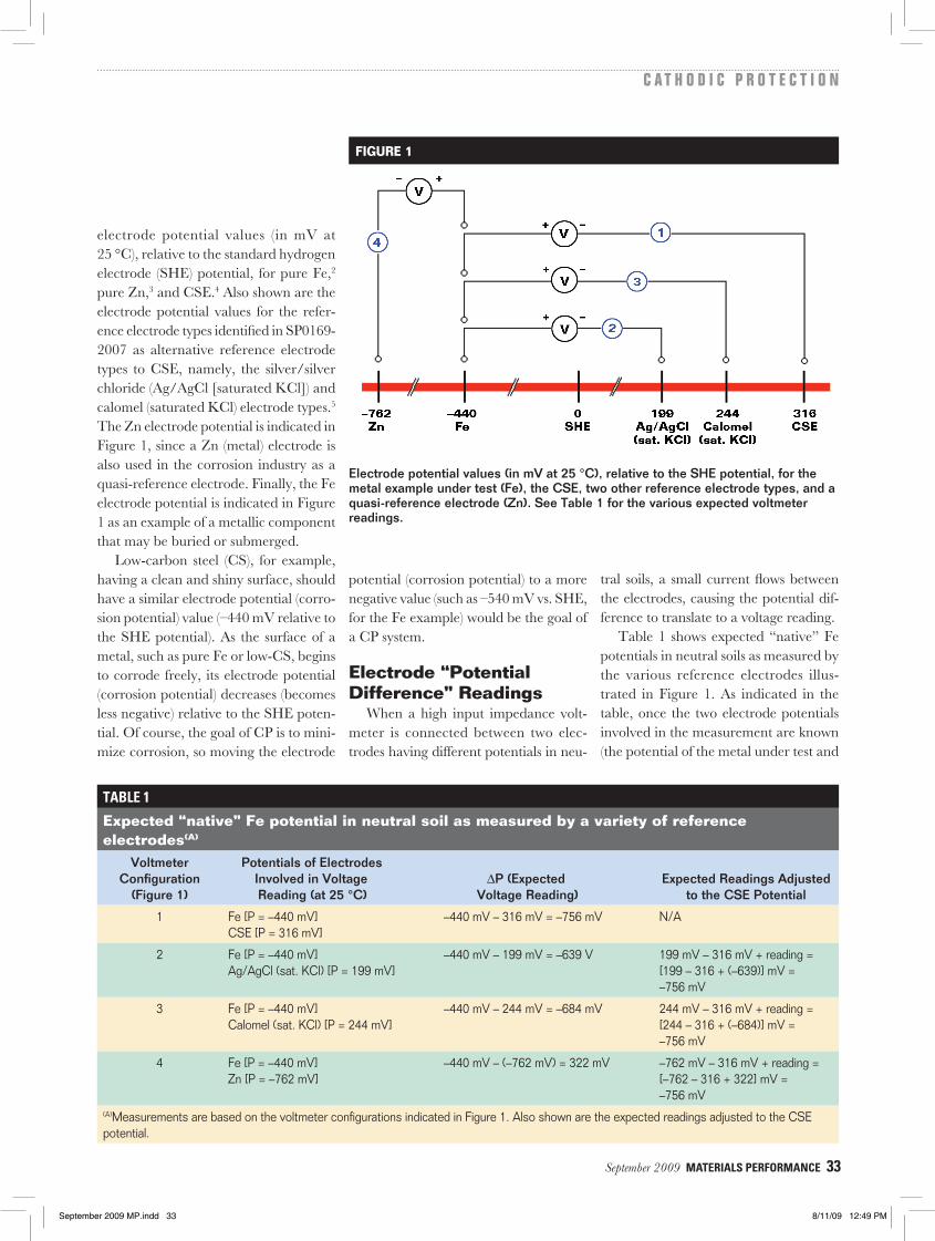
electrode potential values (in mV at 25 °C), relative to the standard hydrogen electrode (SHE) potential, for pure Fe,2 pure Zn,3 and CSE.4 Also shown are the electrode potential values for the refer-ence electrode types identified in SP0169-2007 as alternative reference electrode types to CSE, namely, the silver/silver chloride (Ag/AgCl [saturated KCl]) and calomel (saturated KCl) electrode types.5 The Zn electrode potential is indicated in Figure 1, since a Zn (metal) electrode is also used in the corrosion industry as a quasi-reference electrode. Finally, the Fe electrode potential is indicated in Figure 1 as an example of a metallic component that may be buried or submerged.
Low-carbon steel (CS), for example, having a clean and shiny surface, should have a similar electrode potential (corro-sion potential) value (–440 mV relative to the SHE potential). As the surface of a metal, such as pure Fe or low-CS, begins to corrode freely, its electrode potential (corrosion potential) decreases (becomes less negative) relative to the SHE poten-tial. Of course, the goal of CP is to mini-mize corrosion, so moving the electrode
potential (corrosion potential) to a more negative value (such as –540 mV vs. SHE, for the Fe example) would be the goal of a CP system.
Electrode “Potential Difference” Readings
When a high input impedance volt-meter is connected between two elec-trodes having different potentials in neu-
tral soils, a small current flows between the electrodes, causing the potential dif-ference to translate to a voltage reading.
Table 1 shows expected “native” Fe potentials in neutral soils as measured by the various reference electrodes illus-trated in Figure 1. As indicated in the table, once the two electrode potentials involved in the measurement are known (the potential of the metal under test and
Electrode potential values (in mV at 25 °C), relative to the SHE potential, for the metal example under test (Fe), the CSE, two other reference electrode types, and a quasi-reference electrode (Zn). See Table 1 for the various expected voltmeter readings.
FIGURE 1
TAbLE 1
Expected “native” Fe potential in neutral soil as measured by a variety of reference electrodes(A)
Voltmeter Configuration
(Figure 1)
Potentials of Electrodes Involved in Voltage Reading (at 25 °C)
∆P (Expected Voltage Reading)
Expected Readings Adjusted to the CSE Potential
1 Fe [P = –440 mV] CSE [P = 316 mV]
–440 mV – 316 mV = –756 mV N/A
2 Fe [P = –440 mV] Ag/AgCl (sat. KCl) [P = 199 mV]
–440 mV – 199 mV = –639 V 199 mV – 316 mV + reading = [199 – 316 + (–639)] mV = –756 mV
3 Fe [P = –440 mV] Calomel (sat. KCl) [P = 244 mV]
–440 mV – 244 mV = –684 mV 244 mV – 316 mV + reading = [244 – 316 + (–684)] mV = –756 mV
4 Fe [P = –440 mV] Zn [P = –762 mV]
–440 mV – (–762 mV) = 322 mV –762 mV – 316 mV + reading = [–762 – 316 + 322] mV = –756 mV
(A)Measurements are based on the voltmeter configurations indicated in Figure 1. Also shown are the expected readings adjusted to the CSE potential.
September 2009 MP.indd 33 8/11/09 12:49 PM
34 MATERIALS PERFORMANCE September 2009
C A T H O D I C P R O T E C T I O N A Guide to Understanding Reference Electrode Readings
TAbLE 2
Expected “native” Fe potential in neutral soil as measured by a number of Ag/AgCl reference electrodes having various molarities of KCl filling solution(A)
Voltmeter Configuration
(Figure 2)
Potentials of Electrodes Involved in Voltage Reading (at 25 °C)
∆P (Expected Voltage Reading)
Expected Readings Adjusted to the CSE Potential
1 Fe [P = –440 mV] CSE [P = 316 mV]
–440 mV – 316 mV = –756 mV N/A
2 Fe [P = –440 mV] Ag/AgCl (sat. KCl) [P = 199 mV]
–440 mV – 199 mV = –639 V 199 mV – 316 mV + reading = [199 – 316 + (–639)] mV = –756 mV
3 Fe [P = –440 mV] Ag/AgCl (3.5 M KCl) [P = 205 mV]
–440 mV – 205 mV = –645 mV 205 mV – 316 mV + reading = [205 – 316 + (–645)] mV = –756 mV
4 Fe [P = –440 mV] Ag/AgCl (1.0 M KCl) [P = 222 mV]
–440 mV – 222 mV) = –662 mV 222 mV – 316 mV + reading = [–222 – 316 + (–662)] mV = –756 mV
5 Fe [P = –440 mV] Ag/AgCl (0.5 M KCl) [P = 250 mV]
–440 mV – 250 mV = –690 mV 250 mV – 316 mV + reading = [250 – 316 + (–690)] mV = –756 mV
(A)Measurements are based on the voltmeter configurations indicated in Figure 2. Also shown are the expected readings adjusted to the CSE potential.
the potential of the reference electrode in use), expected readings can be deter-mined. As the table illustrates, since the potentials of the various reference elec-trodes are different from each other, different Fe potentials are expected vs. the different reference electrodes.
All of the voltage reading values shown in Table 1 (and also in Tables 2 and 3) correspond to a particular voltmeter configuration—namely, the positive side
of the voltmeter connects to the metal under test, which is Fe in the example shown, and the negative side of the volt-meter connects to the reference electrode. For a given reference electrode in use, for example a CSE, the potential value of the metal under test will determine the volt-age reading. As indicated in Table 1, a “native” Fe potential of –440 mV vs. SHE will yield a voltage reading of –756 mV vs. CSE. If, however, the Fe is polarized
by a CP system to, say, 100 mV above the native potential, the effective Fe po-tential will be –540 mV vs. SHE and the “instant-off” voltage reading will be –856 mV vs. CSE (–540 mV minus 316 mV).
Universal Adjustment Formula
As the tables indicate, voltage readings taken vs. a non-CSE reference electrode can be adjusted to the CSE potential.
TAbLE 3
Expected “native” Fe potential as measured by Ag/AgCl elements directly exposed to seawater and diluted-seawater electrolytes(A)
Voltmeter Configuration
(Figure 3)
Potentials of Electrodes Involved in Voltage Reading (at 25 °C)
∆P (Expected Voltage Reading)
Expected Readings Adjusted to the CSE Potential
1 Fe [P = –440 mV] CSE [P = 316 mV]
–440 mV – 316 mV = –756 mV N/A
2 Fe [P = –440 mV] Ag/AgCl (seawater) [P = 250 mV]
–440 mV – 250 mV = –690 V 250 mV – 316 mV + reading = [250 – 316 + (–690)] mV = –756 mV
3 Fe [P = –440 mV] Ag/AgCl (<1% seawater) [P = 370 mV]
–440 mV – 370 mV = –810 mV 370 mV – 316 mV + reading = [370 – 316 + (–810)] mV = –756 mV
(A)Measurements are based on the voltmeter configurations indicated in Figure 3. Also shown are the expected readings adjusted to the CSE potential.
September 2009 MP.indd 34 8/11/09 12:49 PM
September 2009 MATERIALS PERFORMANCE 35
C A T H O D I C P R O T E C T I O N
Equation (1) is a universal adjustment formula for the voltmeter configuration shown in Figure 1.
Reading adjusted to CSE potential =
P(RE) – P(CSE) + (reading vs. RE) (1)
where P(RE) is the electrode potential of the electrode in use (vs. SHE), P(CSE) is the electrode potential of a CSE (vs. SHE), and “reading vs. RE” is the volt-age reading taken by the electrode in use. For example, if an “instant-off” voltage reading of 222 mV is recorded from a polarized Fe pipe using a Zn quasi-refer-ence electrode, the voltage reading ad-justed to the CSE potential is –762 mV – 316 mV + 222 mV = –856 mV, since P(Zn) = –762 mV and P(CSE) = 316 mV (Figure 1).
Ag/AgCl “Land-based” Reference Electrodes
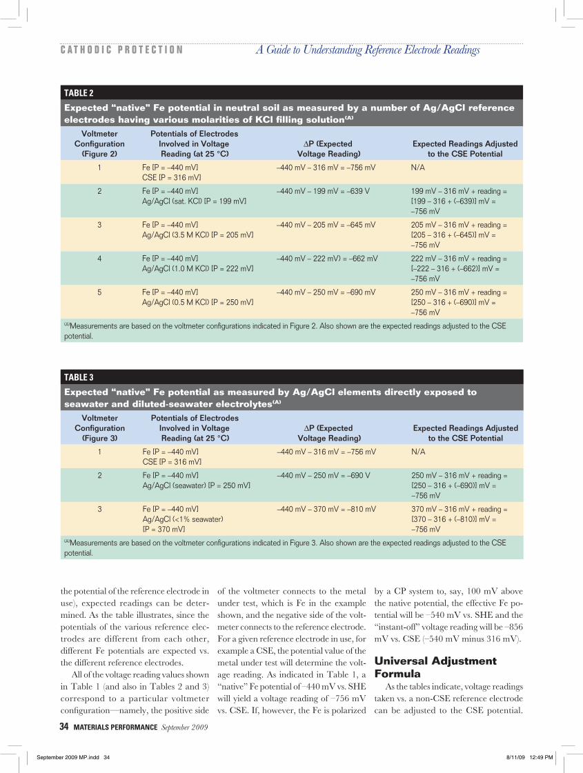
Ag/AgCl reference electrodes that are typically used in land-based applications (i.e., non-submersion applications) have a KCl filling solution to which the Ag/AgCl element makes intimate contact (Figure 2). The KCl solution can have a variety of molarities (concentrations) and the molarity of the KCl filling solution determines the electrode potential for a given KCl solution temperature. The maximum KCl concentration is 4.6 M at 25 °C, which represents the solubility limit of KCl in water (at 25 °C). This would be the “saturated” KCl concentra-tion (at 25 °C).
As indicated in Figure 2, the Ag/AgCl electrode potential vs. SHE varies sig-nificantly with KCl filling solution molar-ity in the range of 4.6 M (saturated) to 0.5 M. Consequently, as indicated in Table 2, expected “native” Fe potentials in neutral soils measured vs. Ag/AgCl (KCl filling solution) reference electrodes are significantly dependent on the specified KCl molarity. As above, readings can be adjusted to the CSE potential. For ex-
Electrode potential values (in mV at 25 °C), relative to the SHE potential, for the metal example under test (Fe), the CSE, and a number of Ag/AgCl electrodes having various molarities of KCl filling solution. See Table 2 for the various expected voltmeter readings.
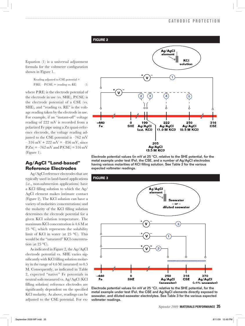
Electrode potential values (in mV at 25 °C), relative to the SHE potential, for the metal example under test (Fe), the CSE and Ag/AgCl elements directly exposed to seawater, and diluted-sea water electrolytes. See Table 3 for the various expected voltmeter readings.
FIGURE 2
FIGURE 3
September 2009 MP.indd 35 8/11/09 12:49 PM

36 MATERIALS PERFORMANCE September 2009
C A T H O D I C P R O T E C T I O N A Guide to Understanding Reference Electrode Readings
ample, if an “instant-off” voltage reading of –745 mV is recorded from a polarized Fe pipe using an Ag/AgCl (3.5 M KCl) reference electrode, the voltage reading adjusted to the CSE potential is 205 mV – 316 mV + (–745 mV) = –856 mV, since P(Ag/AgCl [3.5 M KCl]) = 205 mV, and P(CSE) = 316 mV (Figure 2).
Ag/AgCl “Seawater” Reference Electrodes
Ag/AgCl reference electrodes that are typically used in submersion applications do not have a KCl filling solution, but rather, the Ag/AgCl element makes direct contact to the electrolyte itself, which is typically seawater (Figure 3). In this sce-nario, the electrode’s potential is a func-tion of the salinity of the electrolyte at a
given electrolyte temperature.6 As shown in Figure 3, a significant range of electrode potentials vs. SHE is indicated for electro-lytes ranging from natural seawater to highly diluted seawater. In turn, as indi-cated in Table 3, expected “native” Fe potential readings recorded using Ag/AgCl (seawater) reference electrodes ex-hibit a range of values. As above, readings can be adjusted to the CSE potential. For example, if an “instant-off” voltage read-ing of –790 mV is recorded from a polar-ized (submerged in natural seawater) Fe pipe using an Ag/AgCl element (seawater) reference electrode, the voltage reading adjusted to the CSE potential is 250 mV – 316 mV + (–790 mV) = –856 mV, since P(Ag/AgCl [seawater]) = 250 mV, and P(CSE) = 316 mV (Figure 3).
ConclusionsAs illustrated in this article, for a given
structure material, a structure-to-electro-lyte reading is significantly dependent on the nature of the reference electrode used in the measurement, and, of primary significance is the electrode potential of the reference electrode in use. Should a reading require adjustment to the CSE potential, the universal adjustment for-mula presented in this article can be employed, assuming that an appropriate electrode potential can be identified, vs. the SHE potential, for the reference elec-trode in use.
References1 NACE Standard SP0169-2007, “Con-
trol of External Corrosion on Under-ground or Submerged Metallic Piping Systems” (Houston, TX: NACE International, 2007).
2 P. Atkins, Physical Chemistry, 6th ed. (New York, NY: W.H. Freeman and Co., 1997).
3 P. Vanysek, “Electrochemical Series,” Handbook of Chemistry and Physics, 88th ed. (Boca Raton, FL: Chemical Rubber Co., 2007).
4 J. Lichtenstein, “Reference Electrodes (Half-Cells),” MP 40, 10 (2001).
5 D.T. Sawyer, A. Sobkowiak, J.L. Roberts, Jr., Electrochemistry for Chemists, 2nd ed. (New York, NY: John Wiley & Sons, 1995).
6 M.H. Peterson, R.E. Groover, “Tests Indicate the Ag/AgCl Electrode is Ideal Reference Cell in Seawater,” MP 11, 5 (1972): pp. 19-22.
ROBERT M. PARK is currently director of research at the M. C. Miller Co., 11640 U.S. Highway 1, Sebastian, FL 32958. Previously, he spent six years as a research scientist with the 3M Co. and 10 years as a professor of materials science and engineering at the University of Florida. He holds B.Sc. and Ph.D. degrees in electronics and electrical engineering from the University of Glasgow, Scotland. He has published more than 70 papers in referenced scientific journals and holds two U.S. patents. He is a six-year member of NACE International.
September 2009 MP.indd 36 8/11/09 12:49 PM