a head-mounted three dimensional display*
TRANSCRIPT

A head-mounted three dimensional display*
by IVAN E. SUTHERLAND**
The University of Utah Salt Lake City, Utah
INTRODUCTION
The fundamental idea behind the three-dimensional display is to present the user with a perspective image which changes as he moves. The retinal image of the real objects which we see is, after all, only two-dimensional. Thus if we can place suitable two-dimensional images on the observer's retinas, we can create the illusion that he is seeing a three-dimensional object. Although stereo presentation is important to the three-dimensional illusion, it is less important than the change that takes place in the image when the observer moves his head. The image presented by the three-dimensional display must change in exactly the way that the image of a real object would change for similar motions of the user's head. Psychologists have long known that moving perspective images appear strikingly three-dimensional even without stereo presentation; the three-dimensional display described in this paper depends heavily on this "kinetic depth effect."1
In this project we are not making any effort to measure rotation of the eyeball. Because it is very difficult to measure eye rotation, we are fortunate that the perspective picture presented need not be changed as the user moves his eyes to concentrate on whatever part of the picture he chooses. The perspective picture presented need only be changed when he moves his head. In fact, we measure only the position and orientation of the optical system fastened to the user's head. Because the optical system determines the virtual screen position and
*The work reported in this paper was performed at Harvard University, supported in part by the Advanced Research Projects Agency (ARPA) of the Department of Defense under contract SD 265, in part by the Office of Naval Research under contract ONR 1866(16), and in part by a long standing agreement between Bell Telephone Laboratories and the Harvard Computation Laboratory. The early work at the MIT Lincoln Laboratory-was also supported by ARPA.
**Formerly of Harvard University
the user's point of view, the position and orientation of the optical system define which perspective view is appropriate.
Our objective in this project has been to surround the user with displayed three-dimensional information. Because we use a homogeneous coordinate representation,2-3 we can display objects which appear to be close to the user or which appear to be infinitely far away. We can display objects beside the user or behind him which will become visible to him if he turns around. The user is able to move his head three feet off axis in any direction to get a better view of nearby objects. He can turn completely around and can tilt his head up or down thirty or forty degrees. The objects displayed appear to hang in the space all around the user.
The desire to surround a user with information has forced us to solve the "windowing" problem. The "clipping divider" hardware we have built eliminates those portions of lines behind the observer or outside of his field of view. I t also performs the division necessary to obtain a true perspective view. The clipping divider can perform the clipping computations for any line in about 10 microseconds, or about as fast as a modern high-performance display can paint lines on a CRT. The clipping divider is described in detail in a separate paper4
in this issue. Because the clipping divider permits dynamic perspective display of three-dimensional drawings and arbitrary magnification of two-dimensional drawings, we feel that it is the most significant result of this research to date.
In order to make truly realistic pictures of solid three-dimensional objects, it is necessary to solve the "hidden line problem." Although it is easy to compute the perspective positions of all parts of a complex object, it is difficult to compute which portions of one object are hidden by another object. Of the software solutions now available,2,5-10 only the MAGI9
and the Warnock10 approaches seem to have potential as eventual real-time solutions for reasonably com-
757

758 Fall Joint Computer Conference, 1968
plex situations; the time required by the other methods appears to grow with the square of situation complexity. The only existing real-time solution to the hidden line problem is a very expensive special-purpose computer at NASA Houston11 which can display only relatively simple objects. We have concluded that showing "opaque" objects with hidden lines removed is beyond our present capability. The three-dimensional objects shown by our equipment are transparent "wire frame" line drawings.
Operation of the display system
In order to present changing perspective images to the user as he moves his head, we have assembled a wide variety of equipment shown in the diagram of Figure 1. Special spectacles containing two miniature cathode ray tubes are attached to the user's head. A fast, two-dimensional, analog line generator provides deflection signals to the miniature cathode ray tubes through transistorized deflection amplifiers. Either of two head position sensors, one mechanical and the other ultrasonic, is used to measure the position of the user's head.
As the observer moves his head, his point of view moves and rotates with respect to the room coordinate system. In order to convert from room coordinates to a coordinate system based on his point of view, a translation and a rotation are required. A computer uses the measured head position information to compute the elements of a rotation and translation matrix appropriate to each particular viewing position. Rather than changing the information in the computer memory as the user
3-0 LINE S SPECIFICATION
IN ROOM
COORDINATES
MATRIX
MULTIPLIER
3-D LINE SPECIFICATION
" IN EYE COORDINATES
CLIPPING
DIVIOER
2-0 LINE SPECIFICATION
" IN SCOPE ~H
COORDINATES
ANALOG DISPLAY DRIVER
FIGURE 1—The parts of the three-dimensional display system
moves his head, we transform information from room coordinates to eye coordinates dynamically as it is displayed. A new rotation and translation matrix is loaded into the digital matrix multiplier once at the start of each picture repetition. As a part of the display process the endpoints of lines in the room coordinate system are fetched from memory and are individually transformed to the eye coordinate system by the matrix multiplier. These translated and rotated endpoints are passed via an intermediate buffer to the digital clipping divider. The clipping divider eliminates any information outside the user's field of view and computes the appropriate perspective image for the remaining data. The final outputs of the clipping divider are endpoints of two-dimensional lines specified in scope coordinates. The two-dimensional line specifications are passed to a buffered display interface which drives the analog line-drawing display.
We built the special-purpose digital matrix multiplier and clipping divider to compute the appropriate perspective image dynamically because no available general-purpose computer is fast enough to provide a flicker-free dynamic picture. Our equipment can provide for display of 3000 lines at 30 frames per second, which amounts to a little over 10 microseconds per line. Sequences of vectors which form "chains" in which the start of one vector is the same as the end of the previous one can be processed somewhat more efficiently than isolated fines. Assuming, however, two endpoints for every line, the matrix multiplier must provide coordinate transformation in about 5 microseconds per end-point. Each matrix multiplication requires 16 accumulating multiplications; and therefore a throughput of about 3,000,000 multiplications per second. The clipping divider, which is separate and asynchronous, operates at about the same speed, processing two end-points in slightly over 10 microseconds. Unlike the fixed time required for a matrix multiplication, however, the processing time required by the clipping divider depends on the data being processed. The time required by the analog line generator depends on the length of the line being drawn, the shortest requiring about 3 microseconds, the longest requiring about 36 microseconds and an average of about 10 microseconds.
The matrix multiplier, clipping divider, and fine-generator are connected in a "pipe-line" arrangement. Data "stream" through the system in a carefully interlocked way. Each unit is an independently timed digital device which provides for its own input and output synchronization. Each unit examines an input flag which signals the arrival of data for it. This data are held until the unit is ready to accept them. As the unit accepts a datum, it also reads a "directive" which tells it what to do with the datum. When the unit has accepted
A Head-Mounted Three Dimensional Display 759
a datum, it clears its input flag. When it has completed its operation, it presents the answer on output lines and sets an output flag to signal that data is ready. In some cases the unit will commence the next task before its output datum has been taken. If so, it will pause in the new computation if it would have to destroy its output datum in order to proceed. Orderly flow of information through the system is ensured because the output flag of each unit* serves as the input flag of the next. The average rate of the full system is approximately the average rate of the slowest unit. Which unit is slowest depends on the data being processed. The design average rate is about 10 microseconds per line.
The computer in this system is used only to process the head-position sensor information once per frame, and to contain and manipulate the three-dimensional drawing. No available general-purpose computer would be fasl enough to become intimately involved in the perspective computations required for dynamic perspective display. A display channel processor serves to fetch from memory the drawing data required to recompute and refresh the CRT picture. The channel processor can be "configured" in many ways so that it is also possible to use the matrix multiplier and clipping divider independently. For example, the matrix multiplier can be used in a direct memory-to-memory mode which adds appreciably to the arithmetic capability of the computer to which it is attached. For two-dimensional presentations it is also possible to bypass the matrix multiplier and provide direct input to the clipping divider and display. These facilities were essential for debugging the various umts independently.
Presenting images to the user
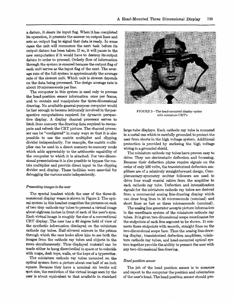
The special headset which the user of the three-dimensional display wears is shown in Figure 2. The optical system in this headset magnifies the pictures on each of two tiny cathode ray tubes to present a virtual image about eighteen inches in front of each of the user's eyes. Each virtual image is roughly the size of a conventional CRT display. The user has a 40 degree field of view of the synthetic information displayed on the miniature cathode ray tubes. Half-silvered mirrors in the prisms through which the user looks allow him to see both the images from the cathode ray tubes and objects in the room simultaneously. Thus displayed material can be made either to hang disembodied in space or to coincide with maps, desk tops, walls, or the keys of a typewriter.
The miniature cathode ray tubes mounted on the optical system form a picture about one half of an inch square. Because they have a nominal six tenths mil spot size, the resolution of the virtual image seen by the user is about equivalent to that available in standard
FIGURE 2—The head-mounted display optics with miniature CRT's
large-tube displays. Each cathode ray tube is mounted in a metal can which is carefully grounded to protect the user from shorts in the high voltage system. Additional protection is provided by enclosing the high voltage wiring in a grounded shield.
The miniature cathode ray tubes have proven easy to drive. They use electrostatic deflection and focussing. Because their deflection plates require signals on the order of only 300 volts, the transistorized deflection amplifiers are of a relatively straightforward design. Complementary-symmetry emitter followers are used to drive four small coaxial cables from the amplifier to each cathode ray tube. Deflection and intensification signals for the miniature cathode ray tubes are derived from a commercial analog line-drawing display which can draw long lines in 36 microseconds (nominal) and short lines as fast as three microseconds (nominal).
The analog line generator accepts picture information in the coordinate system of the miniature cathode ray tubes. I t is given two-dimensional scope coordinates for the endpoints of each line segment to be shown. I t connects these endpoints with smooth, straight lines on the two-dimensional scope face. Thus the analog line-drawing display, transistorized deflection amplifiers, miniature cathode ray tubes, and head-mounted optical system together provide the.ability to present the user with any two-dimensional line drawing.
Head position sensor
The job of the head position sensor is to measure and report to the computer the position and orientation of the user's head. The head position sensor should pro-

760 Fall Joint Computer Conference, 1968
vide the user reasonable freedom of motion. Eventually we would like to allow the user to walk freely about the room, but our initial equipment allows a working volume of head motion about six feet in diameter and three feet high. The user may move freely within this volume, may turn himself completely about, and may tilt his head up or down approximately forty degrees. Beyond these limits, head position cannot be measured by the sensor. We suspect that it will be possible to extend the user's field of motion simply by transporting the upper part of the head position sensor on a ceiling trolley driven by servo or stepping motors. Since the position of the head with respect to the sensor is known, it would be fairly easy to keep the sensor approximately centered over the head.
The head position measurement should be made with good resolution. Our target is a resolution of 1/100 of an inch and one part in 10,000 of rotation. Resolution finer than that is not useful because the digital-to-analog conversion in the display system itself results in a digital "grain" of about that size.
The accuracy requirement of the head position sensor is harder to determine. Because the miniature cathode ray tubes and the head-mounted optical system together have a pin-cushion distortion of about three per-
FIGURE 3—The mechanical head position sensor in use
FIGURE 4—The ultrasonic head position sensor in use
cent, information displayed to tbe user may appear to be as much as three tenths of an inch out of place. Our head position sensor, then, should have an accuracy on the order of one tenth of an inch, although useful performance may be obtained even with less accurate head-position information.
We have tried two methods of sensing head position. The first of these involves a mechanical arm hanging from the ceiling as shown in Figure 3. This arm is free to rotate about a vertical pivot in its ceiling mount. It has two universal joints, one at the top and one at the bottom, and a sliding center section to provide the six motions required to measure both translation and rotation. The position of each joint is measured and presented to the computer by a digital shaft position encoder.
The mechanical head position sensor is rather heavy and uncomfortable to use. The information derived from it, however, is easily converted into the form needed to generate the perspective transformation. We built it to have a sure method of measuring head position.
We have also constructed a continuous wave ultrasonic head position sensor shown in Figure 4. Three transmitters which transmit ultrasound at 37, 38.6, and

A Head-Mounted Three Dimensional Display 761
CRYSTAL OSCILLATORS -
6 - B I T COUNTER -
^*l I I I I Krl I.I I I I KfrTT-TT-TV
FIGURE 5—The ultrasonic head position sensor logic
40.2 kHz are attached to the head-mounted optical system . Four receivers are mounted in a square array in the ceiling. Each receiver is connected to an amplifier and three filters as shown in Figure 5, so that phase changes in sound transmitted over twelve paths can be measured. The measured phase shift for each ultrasonic path can be read by the computer as a separate five-bit number. The computer counts major changes in phase to keep track of motions of more than one wavelength.
Unlike the Lincoln Wand12 which is a pulsed ultrasonic system, our ultransonic head position sensor is a continuous wave system. We chose to use continuous wave ultrasound rather than pulses because inexpensive narrow-band transducers are available and to avoid confusion from pulsed noise (such as typewriters produce) which had caused difficulty for the Lincoln Wand. The choice of continuous wave ultrasound, however, introduces ambiguity into the measurements. Although the ultrasonic head position sensor makes twelve measurements from which head-position information can be derived, there is a wave length ambiguity in each of the measurements. The measurements are made quite precisely within a wave, but do not tell which wave is being measured. Because the wavelength of sound at 40 kHz in air is about 1/3 of an inch, each of the twelve measurements is ambiguous at 1/3 inch intervals. Because the computer keeps track of complete changes in phase, the ambiguity in the measurements shows up as a constant error in the measured distance. This error can be thought of as the "initialization error" of the system. It is the difference between the computer's original guess of the initial path length and the true initial path length.
We believe that the initialization errors can be resolved by using the geometric redundancy inherent in
making twelve measurements. We have gone to considerable effort to write programs for the ultransonic head position sensor. These programs embody several techniques to resolve the measurement ambiguities. Although we have had some encouraging results, a full report on the ultrasonic head position sensor is not yet possible.
The perspective transformation
Generating a perspective image of three dimensional information is relatively easy. Let us suppose that the information is represented in a coordinate system based on the observer's eye as shown in Figure 6. If the two-dimensional scope coordinates, X s and Ya, are thought of as extending from — 1 to + 1 , simple geometric reasoning will show that the position at which a particular point should be displayed on the screen is related to its position in three-dimensional space by the simple relations:
X s = — cotan-z' 2
v ' a Y„ — — cotan-
z' 2
If an orthogonal projection is desired, it can be obtained by making the value of z' constant. Because the perspective (or orthogonal) projection of a straight line in three-dimensional space is a straight line, division by the z' coordinate need be performed oply for the end-points of the line. The two-dimensional analog lihe-
FIGURE 6—The x' y', z' coordinates system based on the observer's eye position

762 Fall Joint Computer Conference, 1968
generating equipment can fill in the center portion of a three-dimensional line by drawing a two-dimensional line. The digital perspective generator computes values only for the endpoint coordinates of a line.
The three-dimensional information to be presented by the three-dimensional display is stored in the computer in a fixed three-dimensional coordinate system. Because this coordinate system is based on the room around the user, we have chosen to call it the "room" coordinate system. The drawing data in the room coordinate system is represented in homogeneous coordinates. This means that each three-dimensional point or end of a three-dimensional line is stored as four* separate numbers. The first three correspond to the ordinary X Y and Z coordinates of three-dimensional space. The fourth coordinate, usually called W, is a scale factor which tells how big a value of X Y or Z represents a unit distance. Far distant material may thus easily be represented by making the scale factor, W, small. Infinitely distant points are represented by setting the scale factor, W, to zero, in which case the first three coordinates represent only the direction to the point. Nearby points are usually represented by setting the scale factor, W, to its largest possible value, in which case the other three coordinates are just the familiar fixed-point representations of X Y and Z.
The matrix multiplier
We have designed and built a digital matrix multiplier to convert information dynamically from the fixed "room" coordinate system to the moving "eye" coordinate system. The matrix multiplier stores a four-by-four matrix of 18 bit fixed-point numbers. Because the draw ing data are represented in homogeneous coordinates, the single four-by-four matrix multiplication provides for both translation and rotation.2 The matrix multiplier accepts the four 18 bit numbers which represent an endpoint, treating them as a four-component vector which it multiplies by the four-by-four matrix. The result is a four-component vector, each component of which is truncated to 20 bits. The matrix multiplier delivers this 80 bit answer to the clipping divider in approximately 5 microseconds. I t therefore performs about three million scalar multiplications per second.
The matrix multiplier uses a separate multiplier module for each column. Each module contains an accumulator, a partial product register, storage for the four matrix elements in that column, and the multiplication logic. The entries of a row of the matrix serve simultaneously as four separate multiplicands. An individual component of the incoming vector serves as the common multiplier. The four multiplications for a
single row are thus performed simultaneously. For additional speed, the bits of the multiplier are examined four at a time rather than individually to control multiple-input adding arrays.
The clipping or windowing task
The job of the clipping divider is to accept three-dimensional information in the eye coordinate system and convert it to appropriate two-dimensional end-points for display. If both ends of the line are visible, the clipping divider needs merely to perform four divisions, one for each two-dimensional coordinate of each end of the line. Enough equipment has been provided in the clipping divider to perform these four divisions simultaneously.
If the endpoints of a line are not within the observer's field of view, the clipping divider must decide whether any portion of the line ig within the field of view. If so, it must compute appropriate endpoints for that portion as illustrated in Figure 7. Lines outside the field of view or behind the user must be eliminated. Operation of the clipping divider is described in a separate paper4 in this issue.
Like the matrix multiplier, the clipping divider is an independently-timed digital device which provides for its own input and output synchronization. I t has an input and an output flag which provide for orderly flow of information through the clipping divider. If a line lies entirely outside the field of view, the clipping divider will accept a new input without ever raising its output flag. Thus only the visible portions of lines that are all or partly visible get through the clipping divider.
SCOPE COORDINATES EYE COORDINATES
Ys= -J-VSy+VCy
FIGURE 7—Clipping and perspective projection in three dimensions

A
Results
I did some preliminary three-dimensional display experiments during late 1966 and early 1967 at the MIT Lincoln Laboratory. We had a relatively crude optical system which presented information to only one of the observer's eyes. The ultransonic head position sensor operated well enough to measure head position for & few minutes before cumulative errors were objectionable. The coordinate transformations and perspective computations were performed by software in the TX-2. The clipping operation was not provided: if any portion of a line was off the screen, the entire line disappeared.
Even with this relatively crude system, the three dimensional illusion was real. Users naturally moved to positions appropriate for the particular views they desired. For instance, the "size" of a displayed cube could be measured by noting how far the observer must move to line himself up with the left face or the right face of the cube.
Two peculiar and as yet unexplained phenomena occurred in the preliminary experiment. First, because the displayed information consisted of transparent "wireframe" images, ambiguous interpretations were still possible. In one picture a small cube was placed above a larger one giving the appearance of a chimney on a house. From viewpoints below the roof where the "chimney" was seen from inside, some concentration was required to remember that the chimney was in fact further away than the building. Experience with physical objects insisted that if it was to be seen, the chimney must be in front.
A second peculiar phenomenon occurred during the display of the bond structure of cyclo-hexane as shown in Figure 8. Observers not familiar with the rippling hexagonal shape of this molecule misinterpreted its shape. Because their view of the object was limited to certain directions, they could not get the top view of the molecule, the view in which the hexagonal shape is most clearly presented. Observers familiar with molecular shapes, however, recognizedthe object as cyclo-hexane.
In more recent experiments with the improved optical system and vastly improved computation capability, two kinds of objects have been displayed. In one test, a "room" surrounding the user is displayed. The room is shown in Figure 9 as it would look from outside. The room has four walls marked N, S, E, and W, a ceiling marked C and a floor marked F. An observer fairly quickly accommodates to the idea of being inside the displayed room and can view whatever portion of the room h6 wishes by turning his head. In another test a small cube was displayed in the center of the user's operating area. The user can examine it from whatever side he desires.
A Head-Mounted Three Dimensional Display 763
"H-FIGURE 8—A computer-displayed perspective view of the
cyclo-hexane molecule
FIGURE 9—A computer-displayed perspective view of the "room" as seen from outside
The biggest surprise we have had to date is the favorable response of users to good stereo. The two-tube optical system presents independent images to each eye. A mechanical adjustment is available to accommodate to the different pupil separations of different users. Software adjustmeots in our test programs also permit us to adjust the virtual eye separation used for the stereo computations. With these two adjustments it is quite easy to get very good stereo presentations. Observers capable of stereo vision uniformly remark on the realism of the resulting images.

764 Fall Joint Computer Conference, 1968
ACKNOWLEDGMENT
When I started work on the head-mounted display I had no idea how much effort would be involved. The project would have died many times but for the spirit of the many people who have become involved. The ultrasonic head-position sensor was designed and built at the MIT Lincoln Laboratory by Charles Seitz and Stylianos Pezaris and is available for our continued use through the cooperation of Lincoln Group 23. Seitz, as a Harvard employee, later designed the matrix multiplier. Robert Sproull, a most exceptionally capable Harvard Senior, simulated, designed most of, built parts of, and debugged the clipping divider. Two graduate students, Ted Lee and Dan Cohen have been an essential part of the project throughout. Our many arguments about perspective presentation, clipping, hidden-line algorithms, and other subject? form one of the most exciting educational experiences I have had. Ted Lee's programs to display curved surfaces in stereo have been the basis for many experiments. Cohen's programs to exercise the entire system form the basis of the demonstrations we can make. I would also like to thank Quintin Foster who supervised construction and debugging of the equipment. And finally, Stewart Ogden, so called "project engineer," actually chief administrator, who defended us all from the pressures of paperwork so that something could be accomplished.
REFERENCES
1 B F GREEN J R Figure coherence in the kinetic depth effect Journal of Experimental Psychology Vol 62 No 3 272-282 1961
2 L G ROBERTS Machine perception of three-dimensional solids M I T Lincoln Laboratory Technical Report No 315 May 22 1963
3 L G ROBERTS Homogeneous matrix representation and manipulation of N-
dimensional constructs The Computer Display Review Adams Associates May 1965
4 R F SPROULL I E SUTHERLAND A clipping divider Proceedings of the Fall Joint Computer Conference 1968 this issue
5 D COHEN A program for drawing bodies with the hidden lines removed A term-project for course 6.539 M I T Fall 1965
6 H T H A Y N E S A computer method for perspective drawing Master's Thesis Texas A&M University Aug 1966
7 P L O U T R E L A solution to the hidden-line problem for computer-drawn polyhedra New York University Technical Report 400-167 (Thesis) Bronx New York September 1967
8 A APPEL The notion of quantitative invisibility and the machine rendering of solids Proceedings of 22nd National Conference ACM ACM Publication p 67 Thompson Book Company Washington DC 1967
9 Mathematical Spplications Group Inc (MAGI) 3-D simulated graphics Datamation February 1968
10 J E WARNOCK A hidden line algorithm for halftone picture representation University of Utah Technical Report 4-5 May 1968
11 Equipment installed at the Manned Space Craft Center at Houston Texas. The project is under the direction of the General Electric Company Electronics Laboratory under NASA Contract No NAS 9-3916
12 L G ROBERTS The Lincoln wand M I T Lincoln Laboratory Report June 1966
13 A C TRAUB Stereoscopic display using rapid varifocal mirror oscillations Applied Optics Vol 6 number 6 June 1967
14 P VLAHOS The three-dimensional display: Its cues and techniques Journal of the Society for Information Display Vol 2 Number 6 Nov/Dec 1965
15 R LAND IE SUTHERLAND Real time color stereo computer displays To be published in Applied Optics