a hello world tutorial for the myir z-turn board (zynq ... · a hello world tutorial for the myir...
TRANSCRIPT
A Hello World tutorial for the MYIR Z-turn board (Zynq 7020 SoC) Thanks to Mr. Juan Abelaira of Akteevy to write this tutorial and share with us.
In this tutorial you will learn to configure the Processing System (PS) for the Z-turn board with an xc7z7020, create a Hello World software application with the Xilinx SDK and run it using the JTAG interface.
Be sure you have the following before starting:
• A Z-turn board, mounted or not on the Cape board • A Xilinx programming cable with standard 14-pin JTAG connector • An A - mini B type USB cable for supply and serial communications with the Z-turn • Xilinx Vivado and SDK installed (I'm using version 2015.4 but it will be similar with other releases) • HyperTerminal, Tera Term or any console application.
Connect the hardware as in the picture above. Use that specific USB port of the Z-turn, not the other one. As for the programming cable, check your connections and cable as your programmer might differ from this one. Refer to the Z-turn schematics and your programmer documentation. The blue LED on the Z-turn should be on and the programmer LED should turn green if correctly connected.
1. Create and configure the Processor System (PS)
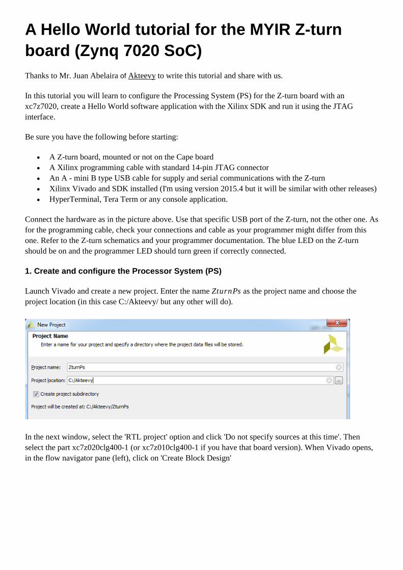
Launch Vivado and create a new project. Enter the name ZturnPs as the project name and choose the project location (in this case C:/Akteevy/ but any other will do).
In the next window, select the 'RTL project' option and click 'Do not specify sources at this time'. Then select the part xc7z020clg400-1 (or xc7z010clg400-1 if you have that board version). When Vivado opens, in the flow navigator pane (left), click on 'Create Block Design'
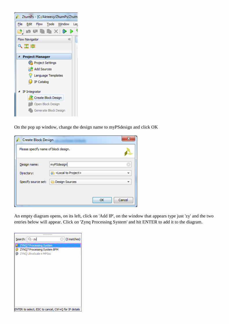
On the pop up window, change the design name to myPSdesign and click OK
An empty diagram opens, on its left, click on 'Add IP', on the window that appears type just 'zy' and the two entries below will appear. Click on 'Zynq Processing System' and hit ENTER to add it to the diagram.
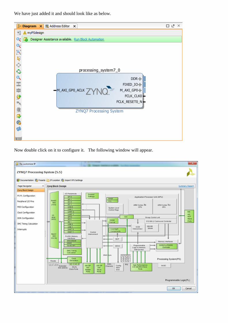
We have just added it and should look like as below.
Now double click on it to configure it. The following window will appear.
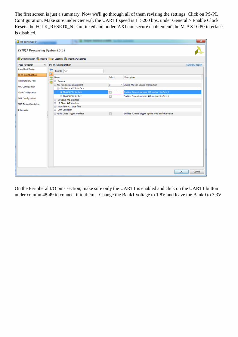
The first screen is just a summary. Now we'll go through all of them revising the settings. Click on PS-PL Configuration. Make sure under General, the UART1 speed is 115200 bps, under General > Enable Clock Resets the FCLK_RESET0_N is unticked and under 'AXI non secure enablement' the M-AXI GP0 interface is disabled.
On the Peripheral I/O pins section, make sure only the UART1 is enabled and click on the UART1 button under column 48-49 to connect it to them. Change the Bank1 voltage to 1.8V and leave the Bank0 to 3.3V

On the MIO Configuration screen, check all the entries are disabled except UART1 and the Bank voltages are as above.

On Clock Configuration, make sure ther input frequency is 33.333 MHz, the CPU clock source is ARM PLL and disable the FCLK_CLK0
On DDR configuration just untick the Enable DDR option as we won't use it for bare-metal applications.
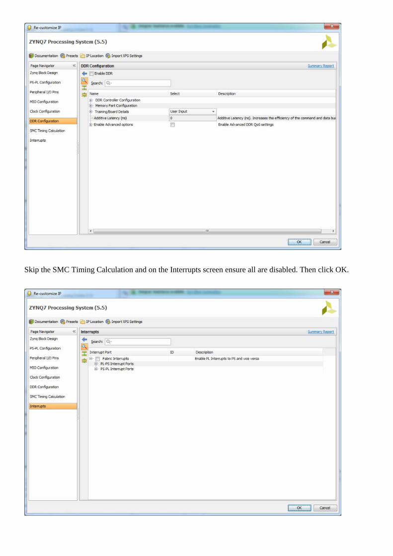
Skip the SMC Timing Calculation and on the Interrupts screen ensure all are disabled. Then click OK.
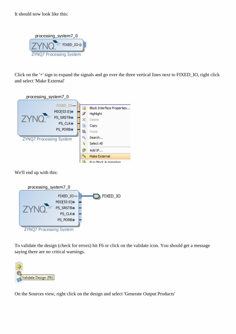
It should now look like this:
Click on the '+' sign to expand the signals and go over the three vertical lines next to FIXED_IO, right click and select 'Make External'
We'll end up with this:
To validate the design (check for errors) hit F6 or click on the validate icon. You should get a message saying there are no critical warnings.
On the Sources view, right click on the design and select 'Generate Output Products'
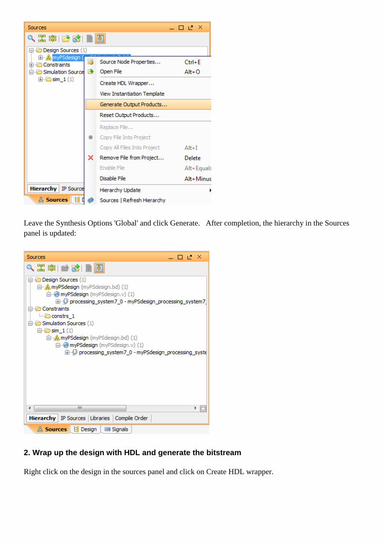
Leave the Synthesis Options 'Global' and click Generate. After completion, the hierarchy in the Sources panel is updated:
2. Wrap up the design with HDL and generate the bitstream
Right click on the design in the sources panel and click on Create HDL wrapper.

On the pop up window, select the option 'Let Vivado manage wrapper' and click OK. We have a now a Verilog top file that instantiates our design. If you generated a VHDL one instead because of your project settings, don’t worry it will do anyways.
Now you can either click on Synthesize, Implement and Generate Bitstream or straight away the last option. It will take a while. Click on the 'Project Summary' button to see the results. You should get a few harmless warnings and the message that the bitstream was generated.
Now click on File > Export > Export Hardware and in the pop up window click on the 'Include bitstream' option. Leave the option <Local to Project>
Now click on File > Launch SDK and leave the options as below. This will load the exported files from Vivado.

After SDK is open you can close Vivado or leave it open.
3. Start the software application in SDK
In SDK we should have on the left panel the hardware platform specification and one of its files (system.hdf) open.
Now click on File > New > Application Project. On the pop up window typeZturnSaysHello as project name and check the other options are as below. Note the Board Supprt Package name has been automatically generated for you after the project name.
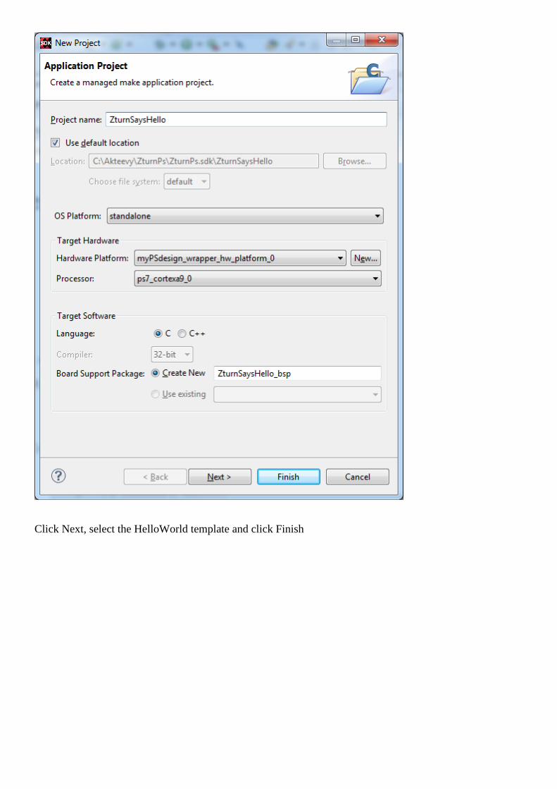
Click Next, select the HelloWorld template and click Finish
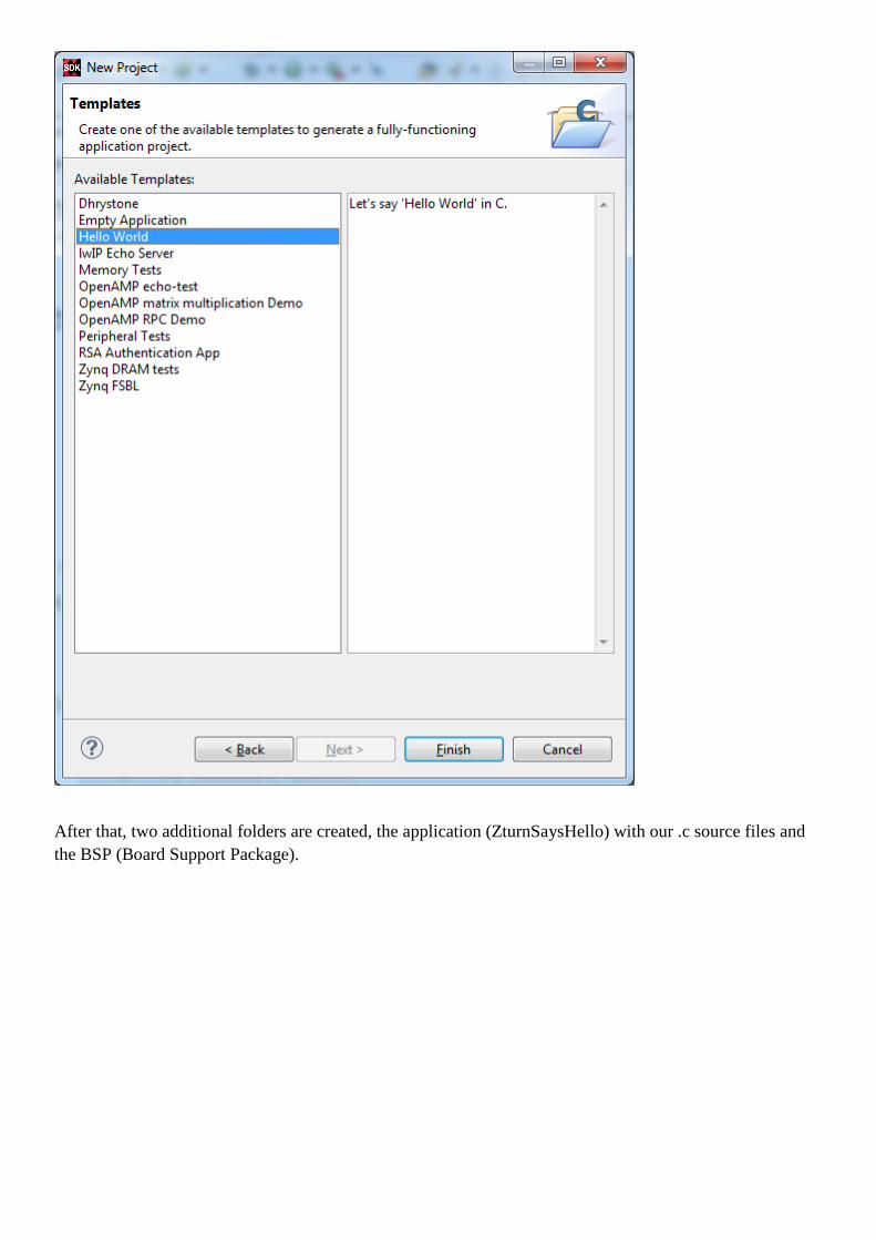
After that, two additional folders are created, the application (ZturnSaysHello) with our .c source files and the BSP (Board Support Package).

Double click the helloworld.c file to open it and change the message to be printed to make it a bit more personal (or just skip that if you prefer)
Click on the down arrow next to the build icon on the top and select the Release option (the Debug will also do). It should automatically build the project (you will notice a window with a progress bar for a second). If not, click again on the 'hammer' button.
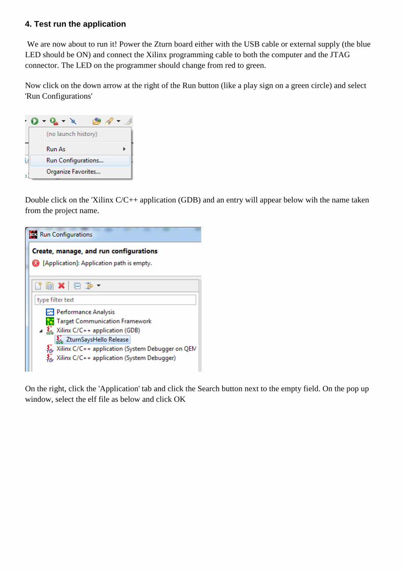
4. Test run the application
We are now about to run it! Power the Zturn board either with the USB cable or external supply (the blue LED should be ON) and connect the Xilinx programming cable to both the computer and the JTAG connector. The LED on the programmer should change from red to green.
Now click on the down arrow at the right of the Run button (like a play sign on a green circle) and select 'Run Configurations'
Double click on the 'Xilinx C/C++ application (GDB) and an entry will appear below wih the name taken from the project name.
On the right, click the 'Application' tab and click the Search button next to the empty field. On the pop up window, select the elf file as below and click OK
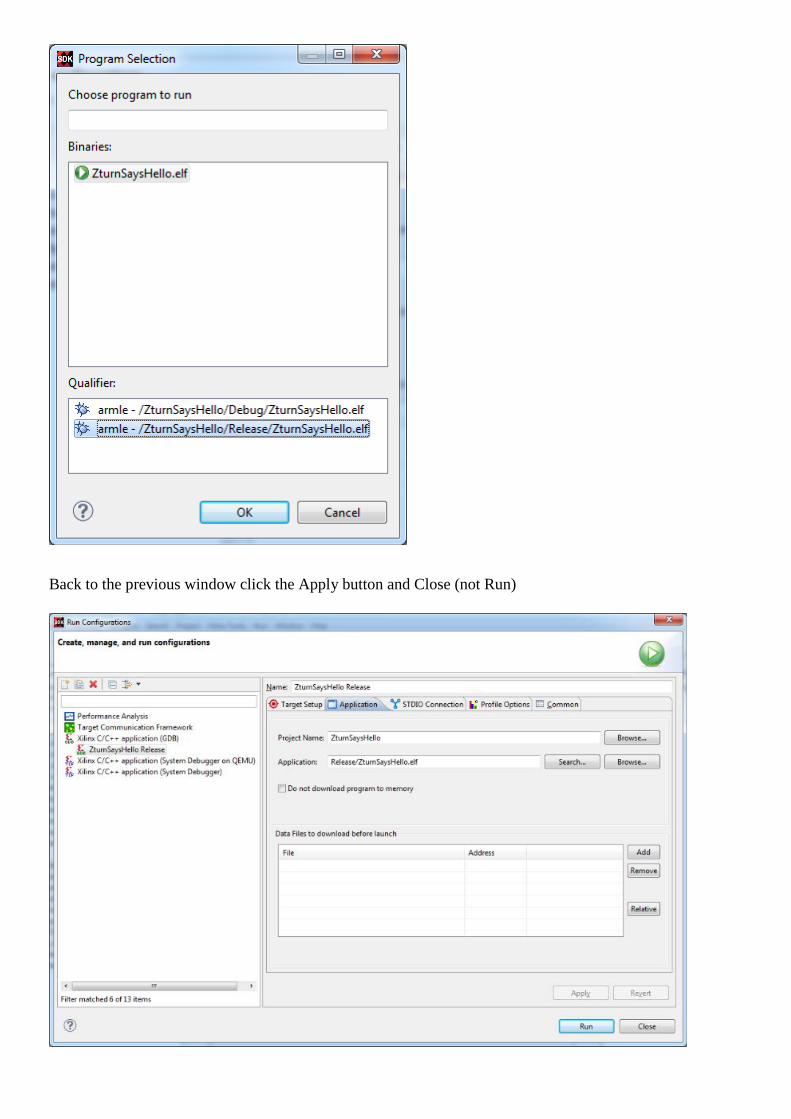
Back to the previous window click the Apply button and Close (not Run)
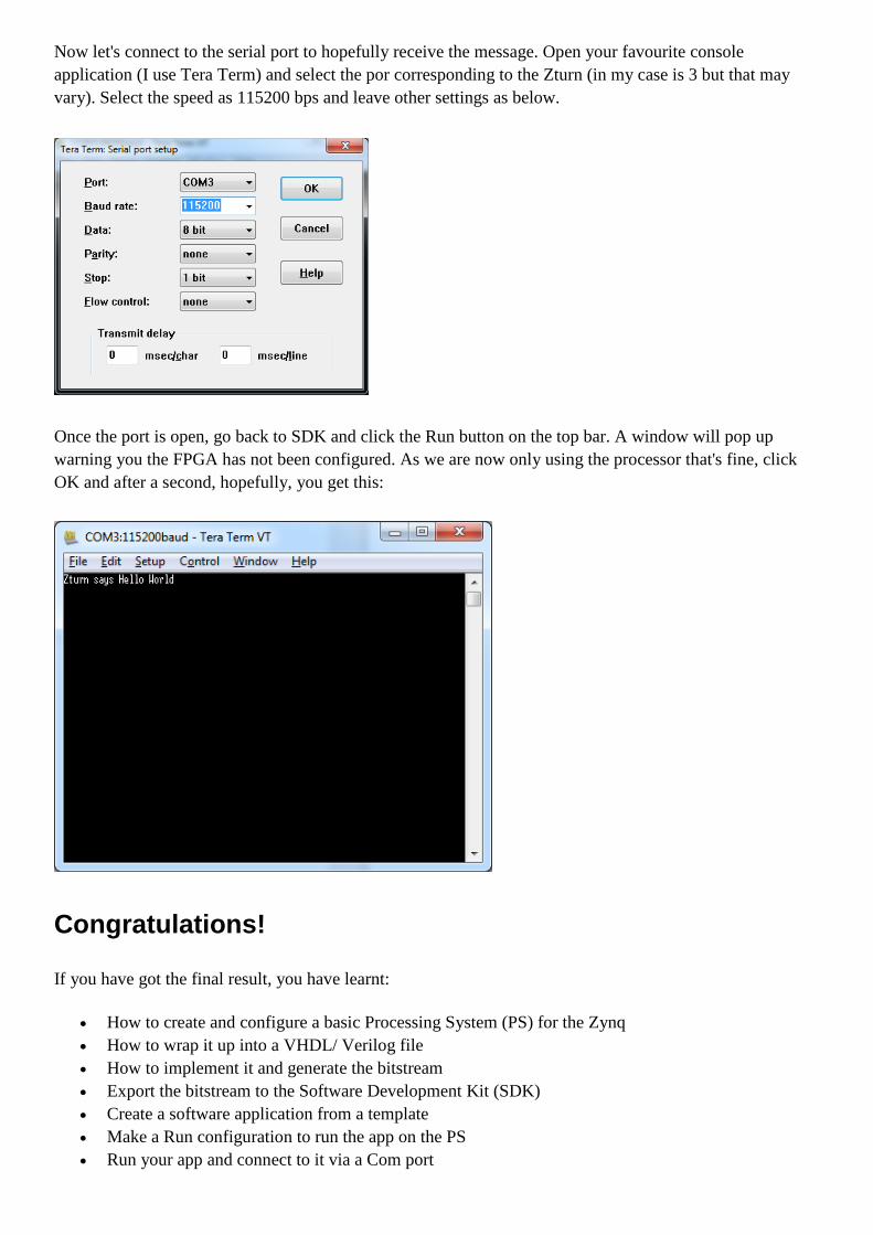
Now let's connect to the serial port to hopefully receive the message. Open your favourite console application (I use Tera Term) and select the por corresponding to the Zturn (in my case is 3 but that may vary). Select the speed as 115200 bps and leave other settings as below.
Once the port is open, go back to SDK and click the Run button on the top bar. A window will pop up warning you the FPGA has not been configured. As we are now only using the processor that's fine, click OK and after a second, hopefully, you get this:
Congratulations!
If you have got the final result, you have learnt:
• How to create and configure a basic Processing System (PS) for the Zynq • How to wrap it up into a VHDL/ Verilog file • How to implement it and generate the bitstream • Export the bitstream to the Software Development Kit (SDK) • Create a software application from a template • Make a Run configuration to run the app on the PS • Run your app and connect to it via a Com port