a hierarchical project-based introduction to digital logic ... hierarchical project-based...
TRANSCRIPT
Paper ID #9432
A Hierarchical Project-Based Introduction to Digital Logic Design Course
Dr. Bill D Carroll P.E., University of Texas, Arlington
Bill Carroll is Professor of Computer Science and Engineering at The University of Texas at Arlington(UTA). He has been a UTA faculty member since 1981 and has held faculty positions at Auburn Universityand visiting appointments at the University of California-Berkeley and the University of Washington. Hehas held engineering positions at Texas Instruments and General Dynamics. Carroll received B.S., M.S.,and Ph.D. degrees in electrical engineering from the University of Texas at Austin. He is a Fellow of theInstitute for Electrical and Electronics Engineers (IEEE) and a licensed professional engineer in Texasand Alabama.
Shawn N Gieser, University Of Texas At Arlington
Shawn N. Gieser PhD Student in Computer Science and part of the Heracleia Human-Centered Comput-ing Laboratory in the Department of Computer Science and Engineering at The University of Texas atArlington. Also, Graduate Teaching Assistant and Lab Instructor for Digital Logic.
Prof. David Levine, University of Texas, Arlington
David Levine teaches at the University of Texas at Arlington in Computer Science and Engineering. Heteaches computer architecture, computer organization, cloud computing and operating systems, in the lastcourse he enjoys using his textbook ”Operating Systems a Spiral Approach” (McGraw-Hill), which heco-authored with Ramez Elmasri and Gil Carrick.
c©American Society for Engineering Education, 2014
Page 24.54.1
A Hierarchical Project-Based Introduction to Digital Logic Design Course
Abstract
Courses in digital logic design are required by most electrical engineering and computer
engineering programs and by many computer science programs. Typically, these courses cover
logic design fundamentals in lectures with applications and technology covered in the laboratory.
As new technologies emerge, it is becoming more and more challenging to incorporate all of the
desired material in a single three or four semester credit hour (SCH) course. At the same time,
many programs are being required to reduce degree requirements and cut support staff making it
difficult to accommodate a second course in digital logic. This paper describes a sophomore-
level, four SCH logic design course that strikes a balance between these conflicting
requirements. The results and experience gained from our course have demonstrated that it is
feasible to successfully cover in one semester a range and depth of topics that many universities
spread over two semesters. Thusly, other universities facing constraints on curricular
requirements and instructional resources may find our approach of interest and beneficial.
The course features a semester-long project to design a four-bit, four-function computer
processing unit, implemented and tested on a field-programmable gate array (FPGA). An
incremental, hierarchical design approach is employed so that the results of lab exercises can be
integrated to produce the final design. Design work is captured and simulated in software, and
some designs are implemented using integrated circuits on solder-less breadboards. This
approach gives students hands-on experience constructing, testing, and debugging circuits that
cannot be gained from FPGA implementation. Laboratory assignments are introduced during
lectures, linking fundamentals covered in the lectures with hands-on experiences, allowing
earlier inclusion of interesting and meaningful laboratory exercises. These exercises and the
final design project are used to address ABET/EAC outcomes (a), (c), and (k).
Introduction
Courses in digital logic design have been taught in various formats for decades and are still
required by virtually all electrical engineering and computer engineering programs and by many
computer science programs1,2,3
. Fundamentals, such as, Boolean algebra, combinational logic,
sequential logic, and finite state machines, still apply. However, technology changes, e.g.,
design software, hardware description languages (HDLs), and field programmable gate arrays
(FPGAs), require that digital logic design courses be revised and updated on a regular basis.
Other factors including accreditation requirements and curricular constraints motivate rethinking
the content and structure of such courses.
This paper describes a sophomore-level, four semester credit hour (SCH) digital logic course
taught in the Computer Science and Engineering (CSE) Department at The University of Texas
at Arlington (UTA). CSE 2441 – An Introduction to Digital Logic has recently been revised and
restructured to address the above, and other, considerations. The course is required for our
computer engineering majors and can be taken as an elective for computer science and software
engineering majors. The results and experience gained from our course have demonstrated that
Page 24.54.2

it is practical to successfully cover, in one semester, a range and depth of topics that many
universities spread over two courses and two semesters. Other universities facing constraints on
curricular requirements and instructional resources may find our approach both interesting and
beneficial.
Features of our course that facilitate student achievement and learning and enable its successful
implementation include the following.
1. Incorporation of an interesting and challenging semester-long design project
2. Use of hierarchical design methods with industry standard CAD software
3. Use of a take-home design kit incorporating industry standard logic devices
4. Emphasis on design fundamentals and applications
5. Close coordination between lectures and laboratory exercises
The remainder of the paper is organized in to four sections – background and motivation, course
description and structure, observations and student survey results, and conclusions and future
plans.
Background and Motivation
This section begins with a brief background of our digital logic course and ends with the
motivation for changes that will be described in later sections. Traditionally, our course had
been taught as a three semester-credit-hour (SCH) lecture course with a separate one SCH lab
course. Students were allowed to take the lab course concurrently with the lecture or in a later
semester. Many students opted for the latter which made coordinating lecture topics with
laboratory exercises almost impossible and often mixed students in the laboratories with varying
levels of understanding of fundamentals. Also, the effectiveness of lectures was diminished
since fundamentals could not be immediately applied and understanding reinforced in the
laboratory. A few years ago, this problem was resolved by combining the two courses in to one
four SCH course.
Two of the most significant changes in digital logic design over the years have been the advent
of computer-aided-design (CAD) tools for design and programmable logic devices (PLDs) for
implementation. Logic circuit simulators and schematic capture software enabled designers and
students to more easily design and verify increasingly complex circuits. Our faculty used
various CAD tools to introduce these important concepts in lectures and laboratories. On the
other hand, programmable logic devices (PLDs) such as programmable logic arrays,
programmable array logic, complex programmable logic devices, and FPGAs were covered only
in lectures. The same was true for HDLs.
Thus, one of the strongest motivations for revising and restructuring our course was to introduce
FPGAs and HDLs. Perhaps the easiest and most effective way to accomplish this would have
been to add a second course. However, this was not an option for us due to curricular limitations
(120 SCH) imposed by the state legislature, the need to accommodate core curriculum
requirements, and faculty/teaching assistant resource limitations due to budget constraints.
This situation provided a great opportunity to take a hard look at course content and structure in
order to identify topics that could be eliminated or condensed to make room for new topics and
Page 24.54.3

ways to reorganize the material to provide a better learning experience for students and to
strength the design content of the course. The use of FPGAs and HDLs in digital logic courses is
not new4,5,6,7
. However, we believe our approach is different from others in that it introduces
industry standard FPGA technology and design tools using a hierarchically-structured semester-
long design project.
Another motivation for revising the course was to more effectively demonstrate ABET/EAC
student outcomes8. The logic design course has been selected by the faculty to cover, in part, the
following three outcomes.
(a) An ability to apply knowledge of mathematics, science, and engineering
(c) An ability to design a system, component, or process to meet desired needs within
realistic constraints …
(k) An ability to use the techniques, skills, and modern engineering tools necessary for
engineering practice
The goals for revising and restructuring the course are the following.
1. Develop a one-semester course in digital logic design that covers both traditional gate-
level and HDL design approaches.
2. Incorporate a semester-long design project to provide students with an introduction to
hierarchical design and a better link of fundamental concepts to practical applications.
3. Strengthen the end-of-term design project by making it the culmination of the semester
project and requiring FPGA implementation.
The approach adopted to address these goals is the incorporation of a semester-long design and
implementation project that follows hierarchical design concepts. This is enabled by the use of
powerful design capture and simulation software during design and easy to use FPGA-based
technology for implementation and testing. Emphasis on fundamentals is maintained by close
linkage of lecture and hands-on laboratory exercises. Laboratory assignments are introduced
during lectures. This provides better connection between the fundamentals being covered in the
lectures and the applications and hands-on laboratory experiences. This approach also allows
for an earlier inclusion of interesting and meaningful laboratory exercises. Our approach is
innovative in that it demonstrates how these and other goals can be realized in a one-semester
course without sacrificing fundamentals. A more detailed description of the course is provided in
the next section.
Course Description and Structure
CSE 2441 – Introduction to Digital Logic is a sophomore-level, four-SCH course taught in a
typical three-hour lecture and three-hour laboratory per week format. The revised course was
first offered in fall 2013. Students may work on laboratory exercises in advance of their
scheduled laboratory session using CAD software and take-home lab kits as described later in
this section. Course objectives are for students to learn the basic concepts, methods, and
technologies needed to analyze, specify, design, build, and test combinational and synchronous Page 24.54.4
sequential logic circuits with standard integrated circuits and programmable logic devices. By
the end of the course, students will have demonstrated an ability to do the following.
1. Apply knowledge of basic discrete mathematics and computer engineering principles.
2. Design small digital systems that meet a specified need within realistic constraints.
3. Use modern industry standard design tools and components.
Prior to taking the logic design course, students will have taken courses in programming and
discrete mathematics. A course in computer organization is taken either in advance or
concurrently with the logic course. An electrical circuits course is a co-requisite but many
students take it in advance of the logic course. Boolean algebra is covered in the discrete
mathematics course and number systems in the programming courses, so these topics are only
reviewed in the logic course, thus freeing up time for other material. See Table 1 for a list of the
course topics.
The main features of the revised course center on a semester-long project involving the design,
implementation, and documentation of the computer processing unit (CPU) for a basic four-bit
digital computer called TRISC (Tiny Reduced Instruction Set Computer). See the Appendix for
a description of TRISC.
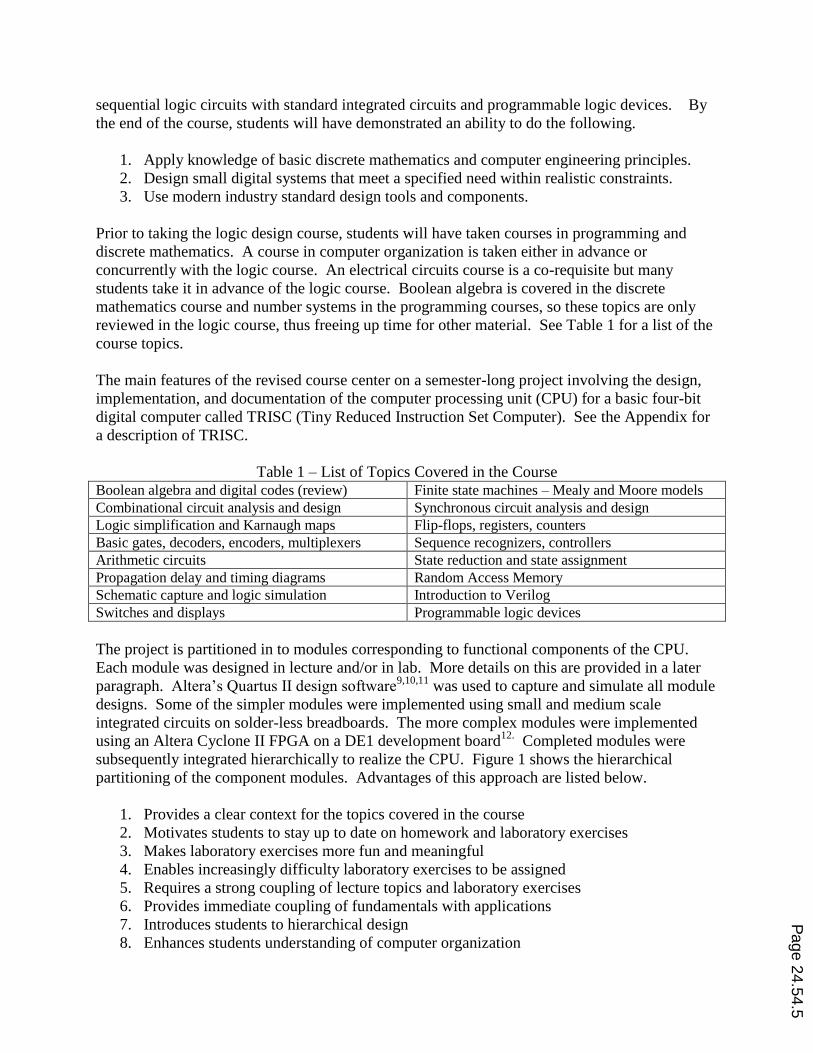
Table 1 – List of Topics Covered in the Course Boolean algebra and digital codes (review) Finite state machines – Mealy and Moore models
Combinational circuit analysis and design Synchronous circuit analysis and design
Logic simplification and Karnaugh maps Flip-flops, registers, counters
Basic gates, decoders, encoders, multiplexers Sequence recognizers, controllers
Arithmetic circuits State reduction and state assignment
Propagation delay and timing diagrams Random Access Memory
Schematic capture and logic simulation Introduction to Verilog
Switches and displays Programmable logic devices
The project is partitioned in to modules corresponding to functional components of the CPU.
Each module was designed in lecture and/or in lab. More details on this are provided in a later
paragraph. Altera’s Quartus II design software9,10,11
was used to capture and simulate all module
designs. Some of the simpler modules were implemented using small and medium scale
integrated circuits on solder-less breadboards. The more complex modules were implemented
using an Altera Cyclone II FPGA on a DE1 development board12.
Completed modules were
subsequently integrated hierarchically to realize the CPU. Figure 1 shows the hierarchical
partitioning of the component modules. Advantages of this approach are listed below.
1. Provides a clear context for the topics covered in the course
2. Motivates students to stay up to date on homework and laboratory exercises
3. Makes laboratory exercises more fun and meaningful
4. Enables increasingly difficulty laboratory exercises to be assigned
5. Requires a strong coupling of lecture topics and laboratory exercises
6. Provides immediate coupling of fundamentals with applications
7. Introduces students to hierarchical design
8. Enhances students understanding of computer organization
Page 24.54.5

TRISC components were designed and implemented in various lecture and laboratory exercises
as will now be described. A full-adder (FA) was designed in lecture and implemented on a
solder-less breadboard in Laboratory Exercise 1. In Exercise 2, the FA design was captured
using Quartus II and saved for use as a component in this and later exercises. A four-bit ripple-
carry adder (RCA) using the full-adder component was then designed and captured for later use.
Laboratory Exercise 3 consisted of the design and implementation of a four-bit two’s
complement adder-subtractor (AddSub) using the previously designed RCA as a component. A
four-bit, four-function (ADD, SUB, AND, XOR) arithmetic logic unit (ALU) was the focus in
Exercise 4. A skeleton of the design was first presented in lecture with the students being
required to complete the detailed design and implement the design on a solder-less breadboard.
An overflow detector (OVR) was also a required component of the ALU. The OVR circuit
design was a lecture exercise with subsequent implementation in the laboratory. Exercise 5
provided students with an introduction to the use of the DE1 including FPGA implementation of
the previously designed two’s complement adder-subtractor.
TRISC
ALU ACC PC Controller RAM
AddSub ANDXOR CNTR MUX CNTR
CNTRFR
FSMIR MUX
FA
OVRRCA
R/W
Figure 1 – Hierarchical Partitioning of TRISC Components
The ALU exercise turned out to be difficult due to both design and implementation complexity.
In response to this experience, exercises 4 and 5 have been flipped for the current offering of the
course so that the ALU implementation can be done on the FPGA rather than the solder-less
breadboard.
Laboratory Exercise 6 required students to design and implement a four-by-four binary array
multiplier and a seven-segment display decoder. Neither of these was used in the TRISC
realization, but the seven-segment display was used to display results in exercise 9 and the term
project. This exercise is being replaced by a finite state machine (FSM) design exercise in the
current offering of the course since FSMs will be needed in a later exercise and in the term
project. The new exercise will become Laboratory Exercise 8 with exercises 7 and 8 becoming 6
and 7, respectively.
Synchronous sequential circuits including D and JK flip-flops and registers were introduced in
Exercise 7. Designs for the instruction register (IR) and flag register (FR) components of the
Page 24.54.6

TRISC Controller were also completed and saved. Exercise 8 covered binary, ring, and twisted-
ring (Johnson) counters and the detail designs of the accumulator (ACC) and Program Counter
(PC) components of TRISC. High-level designs of the ACC and PC were first done as class
exercises.
At this point in the course, students have designed and captured the ALU, ACC, and PC
components of TRISC and the IR and FR subcomponents which will be utilized in the
Controller. Laboratory exercise 9 requires students to complete the design of a controller for
decoding and executing INC and CLR instructions. Students must design an FSM to produce the
appropriate control signals and a counter (CNTR) to sequence the FSM. This exercise is a
stepping stone to the term project in that this controller is relatively straight forward and random
access memory (RAM) is not yet incorporated.
The final term design project requires students to integrate the previously designed and tested
components to implement and demonstrate the CPU on a DE1. The demonstration consisted of
executing a simple program from a RAM provided by the course instructor. The term project
controller has to control instruction execute and fetch cycles for six instructions (CLR, INC,
LDA, STA, ADD, and JMP). Students implementing more than these instructions were given
bonus points. Students were given the option to work on the project at home and/or come to the
laboratory during scheduled hours. They were required to demonstrate their design and
implementation during regular hours on or before its due date. Students were given the option to
use SSI/MSI in the design of their final controller or to use Verilog. One student used Verilog
while the remaining seventeen stayed with schematic design.
These nine laboratory exercises and the term design project are summarized in Table 2. Students
work individually but are encouraged to consult with lab mates or the lab instructor when
needed. The idea is that learning is the priority rather than grades. A positive laboratory
experience promotes interest in the concepts being studied and facilitates learning. However,
students must complete their work during their three-hour lab period and have their work graded
before receiving credit for the exercise. This is workable since students are given a take-home
kit of parts such as ICs, a solder-less breadboard, wire, and a DE1 board so that they can work on
lab exercises in advance. Some exercises have required prelab work. Students were expected to
complete the prelab and begin wiring, when applicable, before coming to their laboratory
session.
Equipment available to students in the laboratory in addition to the take-home parts kit and DE1
include computers running Quartus II and MS Office, IDL 800 Digital Laboratory experimenter,
additional ICs and wire, and various tools. Figure 2 shows photos of the major equipment used
by students in the laboratory.
Students are required to use SSI/MSI-level devices in their designs and to capture and simulate
designs using Quartus II. Electronic design files were saved for all designs which facilitated the
integration of modules for implementing the CPU on the DE1.
Page 24.54.7

Table 2 – Summary of Laboratory Exercises
Exercise # Topic Implementation
Exercise 1 Introduction to the IDL 800 and Basic Gates Solder-less Breadboard
Exercise 2 Introduction to Quartus II Simulation only
Exercise 3 Two’s Complement AdderSubtractor Solder-less Breadboard
Exercise 4 Four-function ALU Solder-less Breadboard
Exercise 5 Introduction to DE1 FPGA
Exercise 6 Array Multiplier and Display FPGA
Exercise 7 Introduction to Synchronous Circuits Solder-less Breadboard
Exercise 8 Counters FPGA
Exercise 9 Processor Control Unit FPGA
Term Project TRISC CPU FPGA
(a) IDL 800 (b) Take-Home Parts Kit (c) DE1
Figure 2 – Major Equipment Used in the Laboratory
Take home laboratory kits for digital logic courses are not new13,14,15,16
. Most of the previous
uses of kits were to replace the need for campus-based facilities and/or to allow laboratory
exercises to be assigned as homework. The kits used in the course described herein are intended
to supplement the on-campus laboratory experience by allowing students the opportunity to
complete routine work such as chip insertion, wiring, and FPGA programming at home, in the
library, or any other convenient location.
The kit consists of an assortment of 25 SSI/MSI integrated circuits selected to allow students
sufficient resources to complete the laboratory exercises and plentiful enough to allow for
individual design differences. The kit also includes a solder-less breadboard that is compatible
with the IDL 800 trainers provided in the laboratory plus assorted lengths and colors of
connector wire. A plastic case is provided to store the parts. A DE1 is also given to the students
to take home.
The decision to provide take-home kits came following numerous student requests in previous
years for extended laboratory hours so that they could complete laboratory exercises in full.
Extended hours were and still are not feasible due to budget constraints. So the options were to
simplify the exercises, open the labs without supervision, or to provide kits. The first option was
not acceptable since it would likely lead to a less rigorous course. The second option was ruled Page 24.54.8
out due to safety and security concerns. Based on reactions of students to the kits and on the
authors’ observations, the kits have provided an effective and cost effective solution.
Observations and Student Survey Results
Note that the following represents the authors’ observations prior to reviewing the results of a
student survey. These results and the authors’ commentary on the results will be presented later
in the section. Students’ understanding of prerequisite materials was uneven which resulted in
more time being spent during lectures than expected on topics such as Boolean algebra and
computer organization. Introducing laboratory exercises in lecture seemed to help students
understand the purpose of the exercises and to give them a heads-up on preparation needed
before their laboratory session. Most students completed prelab work and some or all circuit
wiring before coming to lab. Prepared students generally finished the exercises during their
three-hour laboratory sessions. Unprepared students often did not. Students not having taken a
circuits course prior to the logic design course did not appear to be at a disadvantage.
The semester-long design project did help students understand the importance of the concepts
being covered in lectures and how they relate to the assigned laboratory exercises and
applications in general. Designing a CPU was interesting to the students and seemed to motivate
them to complete the laboratory exercises and the term project. They were also motivated by the
understanding that their designs would be used later in the course as components in a more
complex module. The effectiveness of this approach is evidenced by the fact that all but one
student successfully completed the term project.
Having students design at the SSI/MSI level helped them gain a good understanding of the
fundamentals of combinational and sequential circuits that can be hidden or missed when
designing with HDLs such as Verilog. However, introducing Verilog earlier in the course would
enable students to have the option to use either from that point forward. Requiring students to
construct some realizations on a solder-less breadboard provided valuable lessons on
interconnection complexity and debugging. After all, interconnecting components is still
necessary even though the components may be complex programmable devices. Using the
Cyclone II FPGA for implementation of the more complex designs not only introduced students
to FPGAs but also enabled the hierarchical design project itself to be feasible.
Students were able to easily learn and use the basic features of the Quartus II design capture and
simulation software which gave them experience with industrial standard tools. The simulator
was useful for verifying and debugging designs that were being implemented with SSI/MSI
devices. However for DE1 implementations, students found it quicker and more effective to test
their designs directly on the DE1.
The most difficult design for students was the controller module of the CPU. This was in part
due to the number of states needed in the finite state machine (FSM) for executing two-word
length instructions. Another factor was the absence of a simpler FSM design exercise
previously in the laboratory.
Page 24.54.9

Students were required to write a project report to document their design, implementation, and
test results. The quality of reports was uneven across the class. On reflection, this result is
understandable given that, typically, our students have not taken a technical communications
course before taking the digital logic course.
On the last day of class, students were asked to complete a survey concerning their experiences
relative to laboratory exercises and term project. See Table 3 for a summary of the results. The
same survey will be given at the end of the current (spring 2014) offering of the course.
Generally speaking, the survey results are consistent with the observations of the authors. The
biggest surprise was that students found the solder-less breadboard wiring exercises to be
educational and not excessive in number. It is also interesting to note that only three students
strongly agreed that the term project was difficult while five were neutral and one disagreed.
All students either strongly agreed (9) or agreed (8) that the running design example leading to
the term project was helpful. All students also strongly agreed (12) or agreed (5) that the lab
previews were helpful. Concerning the lab previews helping tie lecture to laboratory, the results
were strongly agree (7), agree (9), and disagree (1). While these results are supportive of the
authors’ observations and the goals for revising the course, stronger benefits were expected.
Table 3 – Summary of Lab Survey Results*
Item Strongly
Agree Agree Neutral Disagree
Strongly
Disagree
Having a take-home parts kit was helpful. 17
Having a take-home DE1 was helpful. 17
Wiring together ICs on a solder-less breadboard was educational.
17
Programming the Cyclone II FPGA on the DE1 was educational. 17
Which lab exercise was the most difficult? 9 students indicated lab 9, 4 lab 7, and 3 lab 4
Which lab exercise was the least difficult? 6 indicated lab 2, 4 lab 1, 4 lab 5, and 2 lab 8
Which lab exercise was the most educational? 10 indicated lab 9, 4 lab 4, 1 lab 3, and 1 lab 6
Which lab exercise was the least educational? 5 indicated lab 1, 5 lab 2, 4 lab 8, and 1 lab 5
The term design project was educational. 11 6
The term design project was difficult. 3 8 5 1
The running design example leading to the term project was an effective approach.
9 8
The lab previews given in lecture were helpful. 12 5
The lab previews helped tie fundamentals from lecture to implementations in lab.
7 9 1
There were too many lab exercises that involved wiring. 1 5 11
There were too many lab exercises. 3 14
The tutorial lab exercises were useful. 10 6 1
The design capture software was easy to learn and use. 8 6 2 1
The logic simulation software was useful for verifying designs. 8 8 1
The laboratory equipment and facilities were adequate. 14 3
The lab exercises helped me gain a better understanding of digital logic circuit analysis and design.
15 2
* There were 18 students in the course with 17 completing the survey. One did not give a definitive answer to
questions 5, 6, 7, and 8.
Page 24.54.10

Conclusions and Future Plans
The goals for the revised course were largely achieved. However observations based on the
authors’ experiences from teaching the course in fall 2013 and feedback from students, suggest
that improvements can be made. The following changes are planned for the spring 2014
offering of the course. Additional changes will be made for 2014-2015 offerings if deemed
necessary from experience gained in the spring. The latest results and plans will be reported at
the conference in June.
1. Articulate more clearly the purpose and scope of the semester-long design project
2. Strengthen sequential circuit design coverage in the lecture and in the laboratory
3. Introduce design using Verilog earlier in the course
4. Redesign TRISC to simplify the controller
5. Introduce a lecture on technical report writing
References
1. Computing Curriculum 2001, Computer Science, IEEE Computer Society Press and ACM Press, December 15,
2001.
2. Computer Engineering 2004, Curriculum Guidelines for Undergraduate Programs in Computer Engineering,
IEEE Computer Society Press and ACM Press, December 12, 2004.
3. Computer Science Curriculum 2008: An Interim Revision of CS 2001, Report from the Interim Review Task
Force, ACM and IEEE Computer Society, December 2008.
4. D. V. Hall, “Teaching Design Methodology and ‘Industry Strength’ EDA Tools in a Frst-Term Freshman
Digital Logic Course,” IEEE Transactions on Education, vol 41, No. 1, pp 45-49, Feb 1998.
5. S. Areibi, “A First Course in Digital Design Using VHDL and Programmable Logic,” 31st ASEE/IEEE
Frontiers in Education Conference, Reno, NV October 10-13, 2001, pp T1C-19 – T1C23.
6. G. A. Vera, et.al., “Integrating Reconfigurable Logic in the First Digital Logic Course,” 9th
International
Conference on Engineering Education, San Juan PR, July 23-28, 2006, pp R1D-10 – R1D-15.
7. E. Todorovich, et.al., “Introducing Programmable Logic to Undergraduate Engineering Students in a Digital
Electronics Course,” IEEE Transactions on Education, vol 55, No. 2, pp 255-262, May 2012.
8. Criteria for Accrediting Engineering Programs, ABET, October 26, 2013.
9. Quartus II Introduction Using Schematic Designs, Quartus II Version 13.0. Altera Corporation – University
Program. May, 2013.
10. Quartus II Introduction Using Verilog Designs, Quartus II Version 13.0. Altera Corporation – University
Program. May, 2013.
11. Introduction to Simulation of Verilog Designs, Quartus II Version 13.0. Altera Corporation – University
Program. February, 2013.
12. DE1 Development and Education Board, User Manual, Altera Corporation, 2006.
13. M. C. Schiffman, B. D. Carroll, and G. R. Kane, "A Take-Home Laboratory Approach for Logic Circuits
Courses," ASEE CoED Transactions, Vol. XI, No. 6, pp. 73-79, June 1979.
14. W. J. Ohley and D. W. Tufts, “’Hands-On’ Microprocessor Education at the University of Rhode Island,” IEEE
Transactions on Education, vol E-24, No. 1, pp 51-54, February 1981.
15. J. M. Long, et.al., “The Use of Home Experimentation Kits for Distance Education Students in First-Year
Undergraduate Electronics,” 2004 ASEE Annual Conference.
16. J. P. Oliver and F. Haim, “Lab at Home: Hardware Kits for a Digital Design Lab,” IEEE Transactions on
Education, vol 52, No. 1, pp 46-51, February 2009.
Page 24.54.11

Appendix – TRISC Description
Organization
Instruction Format
Instruction Set
Instruction Function Micro Operation
LDA Load ACC ACC (MDO)
STA Store ACC RAM (ACC)
ADD ADD ACC ACC (ACC) + (MDO)
SUB Sub ACC ACC (ACC) - (MDO)
XOR XOR ACC ACC (ACC) (MDO)
INC Increment ACC ACC (ACC) + 1
CLR Clear ACC ACC 0
JMP Jump PC (MDO)
JPZ Jump if 0 PC (MDO) if Z = 1
JPN Jump if < 0 PC (MDO) if N = 1
HLT Halt PC 0
Page 24.54.12