a high-q all-fused silica solid-stem wineglass...
TRANSCRIPT

A HIGH-Q ALL-FUSED SILICA SOLID-STEM WINEGLASS HEMISPHERICAL RESONATOR FORMED USING MICRO BLOW
TORCHING AND WELDING Jae Yoong Cho and Khalil Najafi
Center for Wireless Integrated MicroSensing and Systems (WIMS2) University of Michigan, USA
ABSTRACT
We report a new fabrication technology for making fused silica (FS) wineglass resonators with arbitrarily sized FS solid stems through a simultaneous process of micro blow-torching and microwelding. The process allows the welding of multiple FS structures at controlled locations during blow torching. We demonstrate a new micro FS wineglass resonator with high quality factor (Q) and long ring down time (τ). The resonator is formed by blow torching and flowing a thin FS substrate using vacuum to form the resonator shell, and by welding the shell to a solid post at a controlled location. The flowing of the shell and welding to the rod is performed in one step and in a single mold. This solid-stem resonator offers low anchor loss due to the large stem length/stiffness, and small shell rim thickness. The device has a shell radius/height of ~2.8 mm, and a stem radius of 0.5 mm. At <10 µTorr vacuum, the n=2 wineglass mode, located at a frequency (f) of 22.6 kHz, has τ = 35.9 s and Q = 2.55 million.
INTRODUCTION
Three-dimensional (3D) axisymmetric shell resonators are attractive due to their stiffness and damping symmetry. FS is an excellent material for 3D micro shell resonators, because 1) it has very low thermoelastic damping (TED) [1] due to its very low linear thermal expansion coefficient (αFS = 0.52 × 10⁻⁶ K-1) and low thermal conductivity (kFS = 1.38 Wm-1K-1), and 2) it has very low surface energy loss due to its very smooth surface (<1 nm) when reflow molded. We have recently reported a FS micro birdbath (BB) resonator with long τ = 43 s, Q = 1.2 million, frequency symmetry (Δf = 6 Hz), and a high angular gain (Ag (calculated) ~ 0.25) [2]. To improve performance further, the Q of the resonator has to be increased. Several reasons have been identified as the source of lower Q in these small shell resonators [2]. Among these is energy loss through the anchor.
The dependence of Q on anchor design of 3D micro
axisymmetric resonators has been studied by several researchers. The dependence of Q on the anchor stem for a micro hemispherical resonator [3] and on stem length for a silicon oxide micro hemispherical resonator [4] have been studied numerically. The dependence of Q on stem length for a metallic-glass micro hemispherical resonator has been experimentally studied [5]. An analytic expression for reduction in Q due to coupling between the wineglass mode and the bending mode of the stem has been derived in [6]. These studies suggest that stiff, long, and small anchors like that of the hemispherical resonant gyro (HRG) could reduce anchor loss.
Other 3D micro shell geometries have been proposed (Table 1). Most of these resonator geometries have a small device height, short anchor length, small shell thickness near the anchor, or limited control over stem dimensions, which could increase anchor loss, reduce resistance to shock, and reduce angular gain, which is a very important parameter for high-performance gyroscopes. In this work, we present a new FS micro wineglass resonator with a long, solid stem, which is fabricated using microwelding of a FS rod and a FS shell during blowtorch molding. We present the fabrication process, resonance characteristics, and experimental results of the FS micro wineglass resonator.
FABRICATION PROCESS
The fabrication process is described in Figures 1a through 1e. A graphite mold is fabricated from a graphite wafer using a precision milling process and patterned into the shape of a dome, with a through hole (diameter: 1-1.5 mm) formed in the center of the dome. A FS rod is inserted into the through hole (Figure 1a). A FS substrate (100-200 µm) is then clamped on the top of the mold using vacuum. The shell is controllably heated and reshaped by blowtorching the FS substrate above its softening point (1585 °C) with a pressure difference of ~600 Torr across it for ~20s. The FS substrate flows down and where it touches the rod, it is fused to it
Table 1: Comparison of anchor geometries for micro axisymmetric resonators.
A. Hollow anchor for birdbath shell [2, 7].
B. Solid anchor for birdbath shell [7].
C. Boundary anchor for hemispherical shell [8].
D. Short solid anchor for hemispherical shell [4].
E. This work: long solid anchor for hemispherical shell [5, 9].
Challenges: 1) potentially large anchor loss, 2) low shock resistivity.
Challenges: 1) small device height, 2) low shock resistivity.
Challenges: 1) potentially large anchor loss.
Challenges: potentially large anchor loss.
Advantages: 1) potentially low anchor loss, 2) high angular gain, 3) good shock resistivity
978-1-4799-7955-4/15/$31.00 ©2015 IEEE 821 MEMS 2015, Estoril, PORTUGAL, 18 - 22 January, 2015
permanently (Figure 1b). The rod and shell formed by the shape of the mold are thus self-aligned. The combined structure is then detached from the mold (Figure 1c). The shell is then mounted face-up on the bottom surface of a Si releasing jig and is embedded in a polymer (Figure 1d). The shell with its solid stem is released using lapping and chemical mechanical polishing (CMP) processes (Figure 1e).
This process has several attractive features: First, FS microstructures of arbitrary geometries can be fused to create more complex 3D micro sensors and actuators. Second, strong FS fusion bonding between the stem and the shell has very low energy loss at the bonding interface, which is critical for achieving high Q. Third, shells and stems made with different reflowable materials can be also welded. Fourth, sub-nanometer surface roughness can be obtained, which is critical for reducing surface energy loss.
The important resonator design parameters are: mold radius and height, FS rod diameter, and thickness of the FS substrate. The resonator radius (R) is determined by the radius of the dome formed in the mold. The mold used in this study has a radius of 2.5 mm and a height of 3.75 mm. The anchor diameter is determined by the
diameter of the FS rod. The thickness of the shell (t) is determined by the original thickness of the substrate.
(a) Insert fused silica (FS) rod through the through hole at the center of the mold. Clamp a FS substrate (100-200 µm).
(b) Mold the FS substrate using blowtorch at controlled pressure, temperature, and duration.
(c) Detach the shell from the mold.
(d) Attach the shell on a Si jig and embed it in a polymer. Release the resonator using lapping and chemical mechanical polishing processes.
(e) Dissolve polymer. Figure 1: Fabrication process flow.
(a)
(b)
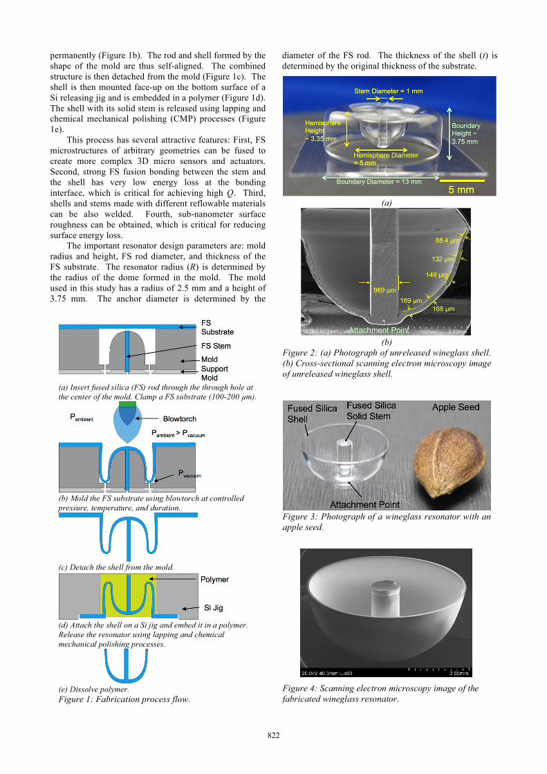
Figure 2: (a) Photograph of unreleased wineglass shell. (b) Cross-sectional scanning electron microscopy image of unreleased wineglass shell.
Figure 3: Photograph of a wineglass resonator with an apple seed.
Figure 4: Scanning electron microscopy image of the fabricated wineglass resonator.
822

Figure 2a shows the photograph of a reflown and molded shell. The hemisphere has a diameter of 5 mm, a height of 3.35 mm, and a stem diameter of 1 mm. The boundary has a diameter of 13 mm and a height of 3.75 mm. Figure 2b shows the cross-sectional scanning electron microscope (SEM) image of an unreleased shell. The homogeneous and seamless welded interface between the shell and the stem is clearly visible.
Figure 3 shows a micro hemispherical resonator. The resonator has an outer radius (R) of ~2.8 mm, an anchor radius (AR) of 0.5 mm, a height (H) of ~2.8 mm, and a rim thickness (trim) of ~90 µm. This resonator resembles the HRG. The SEM image the polished and smooth wineglass resonator rim is shown in Figure 4.
As shown in Figure 2b, the shell thickness increases from the top (ttop = 88.4 µm) to the bottom (tbottom = 169 µm). This thickness profile is the opposite of that of the BB resonator [2]. This gradual increase in the shell thickness from the rim to the anchor will help improve the Q and reduce shock and vibration sensitivity due to the high mechanical stiffness near the anchor and low mechanical stiffness near the rim. FINITE ELEMENT METHOD SIMULATION
A finite element method (FEM) model of the wineglass resonator is built based on the cross-sectional SEM image of a fully released resonator. The resonator has R = 2.76 mm, AR = 0.5 mm, H = 2.8 mm, trim = 90 µm, and tbottom = 148 µm. The n=2 wineglass mode is found at 19.85 kHz. Below the wineglass mode, the rotating mode (frotating) is found at 5.3 kHz, the tilting modes (ftilting) are found at 6.2 kHz, and the anchor bending modes (fbending) are found at 11.7 kHz. These are called parasitic modes, because they couple to external
shock or vibration and can create additional error for the gyroscope. These frequencies can be increased by changing the size of the anchor.
The effective mass (Meff) and Ag are key parameters affecting the gyro performance. Meff is the mass of the gyro when it is modeled as a lumped-mass gyroscope, that is, when the entire proof mass is modeled to have the same vibration amplitude. Meff increases with t. Ag is the scale factor of a rate-integrating gyroscope. Ag increases with the height-to-radius (H/R) ratio, because the shell moves increasingly perpendicularly to the yaw axis due to increased vertical stiffness. Meff and Ag are numerically calculated using ANSYS [10]. Due to the large t (> 90 µm) and H/R (~1), this resonator has large Meff (= 1.8 mg) and Ag (= 0.25). Table 2 summarizes the modal characteristics and physical parameters of the hemispherical resonator.
TESTING
The resonator is mounted face down on a Si substrate using glass frit. The Si anchor has ~300 µm step height between the pedestal and the boundary. The resonator is mounted on top of a piezoelectric actuator. The piezoelectric actuator is mounted on the sidewall of a metal block in a vacuum chamber. The vacuum chamber is pumped down to <10 µTorr pressure. The resonator is
Table 2: Dimensions, resonance frequencies, and physical parameters for micro hemispherical resonator.
R = 2.76 mm H = 2.8 mm AR = 0.5 mm trim = 90 µm tbottom= 148 µm Δt/ΔH = 0.02 µm/µm
fn=2 19.85 kHz Effective mass (Meff) 1.8 mg Angular gain (Ag) 0.25
n=2 wineglass mode (fn=2 = 19.9 kHz)
Rotating mode (frotating = 5.3 kHz)
Tilting mode (ftilting = 6.2 kHz)
Bending mode (fbending = 11.7 kHz)
(a)
(b)
Figure 5: (a) Vacuum Laser Doppler Velocimetry (LDV) setup diagram. (b) Photograph of micro hemispherical resonator mounted on piezoelectric actuator.
823

driven at the fn=2 using the piezoelectric actuator to sustain a certain vibration amplitude. The driving voltage is then turned off, and the resonator amplitude decays exponentially. The ring-down time, τ, is determined as the time it takes for the vibration amplitude to reach 1/e (~ 0.3678) of the original amplitude. Figure 6 shows the ring down time of one of the wineglass modes found at 22.6328 kHz. The τ and Q (Q = πfτ) are found to be 35.9 s and 2.55 million, respectively. The other n=2 mode is located at 22.496 kHz with τ ~ 5s (Q = 0.35 million). The reason for the large difference in τ between these two nodes has not been identified yet and is currently being investigated.
Figure 6: Ring down plot of the wineglass resonator measured using Laser Doppler Vibrometer (LDV) at <10 µTorr vacuum. fn=2 = 22.633 kHz, τ =35.9 s, and Q = 2.55 million.
SUMMARY
We demonstrated a new fabrication technology for making FS wineglass resonators with arbitrarily sized FS solid stems through a simultaneous process of micro blow-torching and microwelding. The process allows the welding of multiple FS structures at controlled locations during blow torching. The resonator is formed by blow torching and flowing a thin FS substrate using vacuum to form the resonator shell, and by welding the shell to a solid post at a controlled location. The flowing of the shell and welding to the rod is performed in one step and in a single mold, so the shell and rod are self aligned. This solid-stem resonator offers low anchor loss due to the large stem length/stiffness, and small shell rim thickness. The device has a shell radius/height of ~2.8 mm, a stem radius of 0.5 mm, and a rim thickness of 90 µm, and a shell thickness 148 µm near the anchor. The resonator has large effective mass (= 1.8 mg) and high angular gain (= 0.25). At <10 µTorr vacuum, the n=2 wineglass mode, located at a frequency of 22.6 kHz, has τ = 35.9 s and Q = 2.55 million.
ACKNOWLEDGEMENTS
This work is supported by DARPA MRIG award #W31P4Q-11-1-0002. The authors thank Mr. Ali Darvishian, Dr. Behrouz Shiari, Mr. Robert Gordenker,
and Mr. Tal Nagourney for the testing support. Portions of this work were done in the Lurie Nanofabrication Facility (LNF), a site of the National Nanotechnology Infrastructure Network (NNIN). REFERENCES [1] R. Lifshitz and M. L. Roukes, “Thermoelastic
damping in micro and nanomechanical systems,” Phys. Rev. B, vol. 61, n. 8, 2000, pp. 5600-5609.
[2] J. Cho et al., “Fused silica micro birdbath shell resonators with 1.2 million Q and 43 second decay time constant,” in Proc. Hilton Head 2014, pp. 103-104.
[3] D. Senkal et al., “Titania silicate/fused quartz glass blowing for 3-D fabrication of low internal loss wineglass micro-structures,” in Proc. Hilton Head 2012, pp. 267-270.
[4] L. Sorenson and F. Ayazi, “Effect of structural anisotropy on anchor loss mismatch and predicted case drift in future micro-hemispherical resonator gyros,” in Proc. IEEE/ION PLANS 2014, pp. 493-498.
[5] Kanik et al., “Metallic glass hemispherical shell resonators,” JMEMS [Online]. Available: http://ieeexplore.ieee.org/xpls/abs_all.jsp?arnumber=6937058
[6] Y. K. Zhbanov and V. P. Zhuravlev, “Effect of movability of resonator center on the operation of a hemispherical resonator gyro,” Mechanics of Solids, 2007, vol. 42, no. 6, pp. 851-859.
[7] D. Senkal et al., “Design and modeling of micro-glassblown inverted wineglass structures,” in Proc. ISISS 2014, pp. 13-16.
[8] A. Vafanejad and E. S. Kim, “Sub-degree angle detection using dome –shaped diaphragm resonator with wine-glass mode vibration,” in Proc. Hilton Head 2014, pp. 391-394.
[9] E. J. Loper, Jr. and D. D. Lynch, “Vibratory rotation sensor,” U.S. Patent 4 901 508.
[10] J. Cho, “High-performance micromachined vibratory rate- and rate-integrating gyroscopes,” Ph.D. dissertation, Dept. EECS, Univ. Michigan, Ann Arbor, MI, 2012.
CONTACT
*K. Najafi, [email protected]. J. Cho, [email protected].
824