a high-speed, inertia-free automatic stereoplotting …...senior engineer* general precision, inc.,...
TRANSCRIPT

A High-Speed, Inertia-Free AutomaticStereoplotting Instrumentt **
MORRIS M. BIRNBAUM,
Project Jl,lanager*and
PH IL M. SALOMON,
Senior Engineer*General Precision, Inc.,
Glendale 1, California
ABSTRACT: Stereoplotter, Projection AP-14, developed by the Librascope Groupof General Precision, Inc., is an automated anaglyph plotter which does notrequire a computer for its automation. The instrument represents a novel departure from past attempts to extract contour information: stereomodel contoursare required and recorded without mechanical motion of the flying spot scannertracing table. As a result, contour data may be detected and compiled rapidly.
Electron-beam servoing techniques--i.e., servo control of the scanning pattern of a flying spot scanner-are utilized to trace the contours by the action ofthe scan pattern, which continuously senses the location and direction of equalelevation points in the stereomodel space. The total mass in motion is essentiallythat of an electron beam, which results in inertia-free operation.
The instrument consists of two major systems: a photoscan system and correlator system. A dditional subsystems are provided to integrate the functions of thethe major systems. Use of the instrument's manual and electronic tracing aidsenable an operator to employ it as a conventional stereoplotter.
INTRODUCTION
STEREOPLOTTER, Projection AP-14, Figure1, developed by the Librascope Group of
General Precision, Inc., for Rome Air Development Center (RADC), automaticallysearches for and traces contours and printscontour maps. An anaglyph plotter, to whichhas been added an electronic image-processingsystem, is the basic instrument. No computeris required; closed-loop analog servo systemsperform all of the imagery sensing and contour tracing.
A flying spot scanner tube, which can bemoved up and down, replaces the usual tracing table. The projectors are modified byadding a multiplier phototube in each projector head. The projector heads perform a dualfunction: each head projects light to form theanaglyph stereomodel, and each head receiveslight from the flying spot scanner tube toprocess the imagery in each area of the diapositive. In this particular instrumentation,the two functions are not performed concur-
ren tly, though they can be by adding beamsplitters to the modified projector head optics.
Diapositives are placed in the projectorheads, and the stereomodel is oriented manually. The flying spot scanner tube screen isused as an oversized plotting table surface,with the flying spot being manually positionedby an operator-controlled joystick at variouspositions on the screen surface to orient themodel. When the model is oriented, the multiplier phototubes are rotated into position inthe projector heads; and automatic searchingand plotting of contours begin.
At any elevation, the flying spot movesover the scanner tube surface searching forcontours. \iVhen a contour is intercepted, thesearch mode is interrupted; the con tour isautomatically traced; and the search mode isresumed again. \iVhen all contours at an elevation are traced, a light flashes on an adjacentconsole, notifying an operator to raise thescanner tubes to the next elevation.
A display tube is used for printout. Its
* Surface Equipment Division, Librascope Group.** It is understood that a similar paper was presented at the Tenth International Congress at Lisbon.t Presented at 30th Annual Meeting of the Society, Hotel Shoreham, Washington, D. c., March
17-20, 1964.
842
AUTOMATIC STEREOPLOTTING INSTRUMENT 843
beam moves in synchronism with the DCposition of the scanner beam's center. Thedisplay tube beam is turned on automaticallywhen the scanner beam is tracing a contour.Photographing the face of the display tube, assequential contours are plotted, produces acontour map.
Analog correIators process the electricalsignal coming from each multiplier phototube. The correlators derive servo intelligencenot only as to which direction the beam shallbe moved to intercept a contour but also as towhich direction the beam shall move to followa con tour, once in tercepted.
The instru men tation of the stereoplotter,for performing search, trace, and printout ofcontours by servoing an electron beam, offerstremendous possibilities for high-speed contouring and orthophoto mapping. Some ofthese possibilities have already been realizedin this instrumentation, where contours arebeing traced at from 5 to 15 inches per second,at electronic system "C" factors of over 500.The present configuration and circuitry lendthemselves to producing orthophotos, as wellas contours, using the existing correlationcircuitry and scanning system components.Since the system is basically an analog onewi th several servo loops, and does not requirea computer, it can eventually be produced ata much lower cost than could similar compu ter-con trolled systems.
The stereoplotter instrumentation configuration represents an attempt to devise asystem not limited in its plotting speed by themechanical inertia of a tracing table. Therefore, image-processing techniques and electron-beam servoing techniques have beendeveloped which enable the scanner electronbeam to search for and lock on the con tour,and follow it. If the scanner tube face coversthe area of the neat model, no X or Y motionof the scanner tube is required, and a highspeed system results.
Presently, the tube face covers only part ofthe neat model area, and the tube must beindexed to adjacent positions.
SYSTEM DESCRIPTION
The instrument may be considered to consist of two major systems: (1) a photoscansystem capable of high-speed electronic scanning of a stereo diapositive pair and (2) acorrelation system suitable for processingwide-band electrical signals. Additional subsystems are provided to integrate the majorsystems and to protect the components
MORRIS M. BIRNBAUM
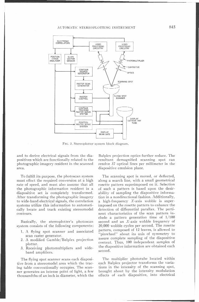
against failure or overload. The basic instrumentation block diagram is shown in Figure 2.
The photoscan system incorporates a modified Gamble/Balplex plotter and a highresolution electronic flying spot scanner capable of extracting wide-band electrical signalsfrom conjugate diapositive areas. Use of asingle scanning source assures perfect alignment of the scanning rasters on each diaposi.tive. The scanning raster is composed of ageometrical rosette pattern with a highfrequency X-axis wobble superimposed on itto enhance differential parallax detection. Therosette pattern occupies a small portion of thetotal scanner face area and can be positionedto anv area of the scanner's face by eithermanu~l or correIa tor control. A beam-intensity feedback system maintains the scanningspot at a constant brightness level.
The correlation svstem includes the necessary electronic circu"its to extract informationregarding the scan pattern's position in modelspace. The correIa tors utilize the informationderived by the photoscan system from thediapositi ves and sense model parameterssuch as height error, slope vector, and information density-in each stereomodel areaoccupied by the scan pattern. Feedback circuits, utilizing the detected model parameters, cause the scan pattern to automaticallylocate and follow any contour that existswithin the model area intercepted by thescanner.
In its present configuration, diapositiveorientation is performed manually, as are the
844 PHOTOGRAMMETRIC ENGINEERING
tasks of scaling and leveling of the stereomodel. The scanning cathode ray tube intercepts a portion of the neat model and automatically extracts contour information forthat portion of the stereomodel. After completing a section of the neat model, the scanner is manually located to the next section.The final map manuscript is compiled byconnecting each of the map sections togetherand observing their proper coordinate location.
Contours are initially acquired by means ofa preprogrammed search pattern which causesthe rosette scan raster to seq uen tially movefrom the center to the edges of the scanner ina series of straight-line search sweeps. Theoperational mode is changed from search tocontour following by continuously monitoringthe level of video signal crosscorrelation.\i\ihen the crosscorrela tion vol tage exceeds apreset level, indicative of no height errorexisting between the scan raster level and thestereomodel surface, the operational mode
required for automatic contour following isactivated; and the contour is traced to theedges of the scan ner cathode-ray tube. Aftertracing the contour, the system automaticallyreturns to the search mode and resumes thesearch mode sequence.
The display, or contour map manuscript, isprepared by photographing a display cathoderay tube whose electron beam is caused tomove in synchronism with the DC position ofthe cen ter of the flying spot scanner tubebeam. The display beam is also activatedwhen the level of video signal crosscorrelationexceeds a preset level and is therefore turnedoff, except when actually tracing a stereomodel con tour. A one-to-one copy cameraphotographs the display cathode-ray tube,thus producing a contour manuscript atstereomodel scale.
PHOTOSCAN SYSTEM
The purpose of the photoscan system is toscan each diapositive forming the stereomodel
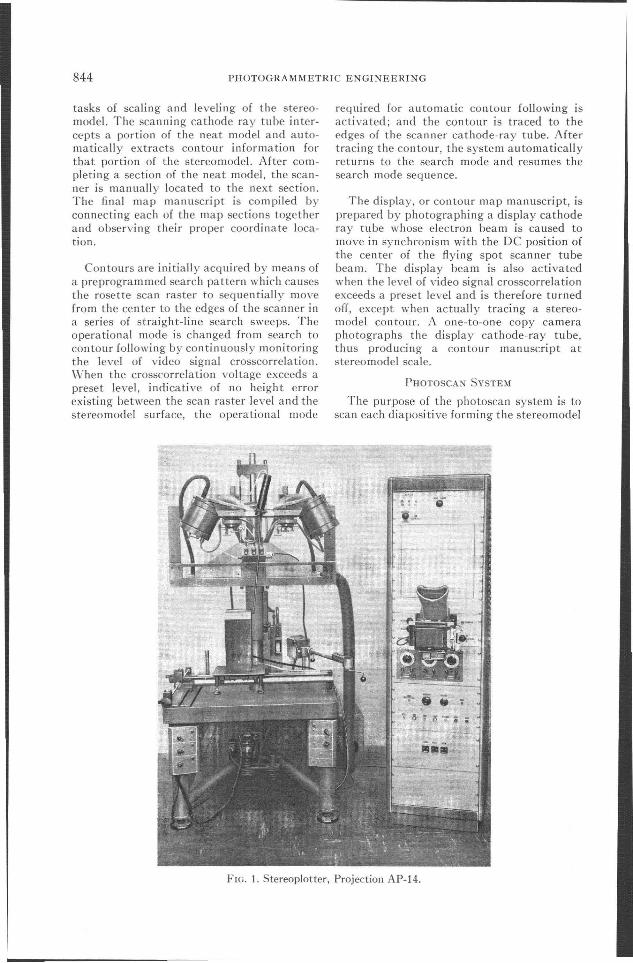
FIG. 1. Stereoplotter, Projection AP-14.
AUTOM,\TIC STEREOPLOTTING lNSTRUMENT 845
ELECTRONICCORRELATORS
)f;OIAPOSITIVE
OPTICS
SCANNING SPOT
b<
FLYING SPOTSCANNER
FIG. 2. Stereoplotter system block diagram.
and to derive electrical signals from the diapositives which are functionally related to thephotographic imagery resident in the scannedarea.
To fulfill its purpose, the photoscan systemmust effect the required conversion at a highrate of speed, and must also assume that allthe photographic information resident in adiapositive set is completely transformed.After transforming the photographic imageryto wide-band electrical signals, the correlationsystems utilize this information to automatically locate and track existing stereomodeicontours.
Basically, the stereoplotter's photoscansystem consists of the following components:
1. A flying spot scanner and associatedscan raster generator.
2. A modified Gamble/Balplex projectionplotter.
3. Receiving photomultipliers and wideband amplifiers.
The flying spot scanner scans each diapositive from a stereomodel area which the tracing table conventionally occupies. The scanner generates an intense point of light, a fewthousandths of an inch in diameter, which the
Balplex projection optics further reduce. Theresultant demagnified scanning spot canresolve 37 optical lines per millimeter in thediapositive emulsion plane.
The scanning spot is moved, or deflected,along a search line, with a small geometricalrosette pattern superimposed on it. Selectionof such a pattern is based upon the desirability of sampling the diapositive information in a nondirectional fashion. Additionally,a high-frequency X-axis wobble is superimposed on the rosette pattern to enhance thedetection of differential parallax. The pertinent characteristics of the scan pattern include a pattern generation time of 1/100second and an X-axis wobble frequency of20,000 wobble cycles per second. The rosettepattern, composed of 12 leaves, is allowed to"pinwheel" about its axis of symmetry toassure complete sampling of the diapositivecontent. Thus, 100 independent samples ofthe diapositive information are obtained eachsecond.
The multiplier phototube located withineach Balplex projector transforms the variations in the in tensity of the scanning spot,brought about by the intensity modulationeffects of each diapositive, into electrical

846 PHOTOGRAMMETRIC ENGINEERING
0102030405060708090
SLOPE ANGLE (OEGREES)
FIG. 3. Rosette scan pattern diameter versusterrain slope angle.
The diameter of the rosette scan pattern iscaused to vary according to the terrain slopeto further en hance the parallax detectioncapabilities of the correIa tors. Feedback signals are generated according to slope andcontour angle measurements which are performed by the correiators. An idealized curveof the rosette pattern diameter as a functionof terrain slope is shown in Figure 3.
AUTOMATIC SEARCH SYSTEM
The purpose of the search system IS to
i = j for the autocorrelation function
where
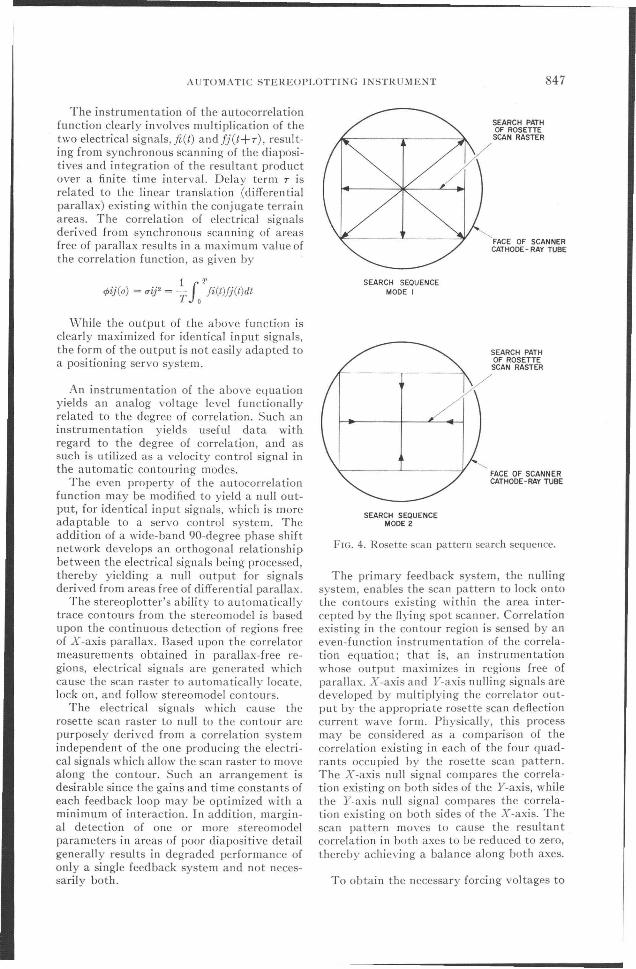
The search pattern selected is a compromisebetween efficiency and ease of instrumentation. The pattern consists of a series ofstraight-line searches which radiate (1) fromthe center of the flying spot scanner tubeduring the first mode of operation and (2)from the edges of the scanner tube inwardtoward the center during the second mode ofoperation. As a stereomodel contour ispri nted, as a resul t of one search Ii ne, thesearch pattern will resume with the nextsequential search line.
The general correlation function is given by
1 7'
q,ij(T) = lim -f fi(t)Jj(t + r)dt1'... ", T 0
Digital circuitry is predominantly used ininstrumenting the automatic search system.Analog operations on selected digi tal pulsesprovide the required wave shapes for searchdeflection. The search system instrumentation provides eight spokes searching outwardfrom the scanner tube center in a linear fashion, followed by four spokes searching fromthe edge of the scan cathode-ray tube inwardto center. Crossing a contour inhibits thesearch generator so that, when it is restarted,the search sequence is continued. After theen tire search pattern has been completed, thesearch system stops; and a visible light indicates to the operator that a new elevationsetting is required in the stereomodel. Thesearch sequence of the rosette scan pattern isshown in Figure 4.
i '"' j for the crosscorrelation function
automatically locate and follow any stereomodel con tours that exist for a particularelevation in model space.
CORRELATION TECHNIQUES UTILIZED
ON CONJUGATE IMAGE
MATCHING
Correlation techniques are utilized to indicate a match of conjugate image points froma stereo diapositive pair. The detection ofsuch a match is fundamental to the problemof locating and tracing stereomodel contours.
and
and the functionsfi(t) andfj(t) are assumed tobe stationary random processes with a delayof T existing between the two functions.
\\\1\
'\
'-'-....
.......I"---I--
_ 20
~
::!
25
a::~w~ 15<l:aza::w>-
~ 10z<l:uen
signals. The photomultipliers are mounted onspecially constructed rotatable turrets whichallow either projection of the diapositives, forstereomodel orientation, or recei pt of themodulated scanner light spot, for automaticmodes of operation. After obtaining the necessary electrical signals, wide-band amplifiersraise the power of the signals to a level suitable for en try in to the correlators.
A beam-in tensity-control feedback systemcontinuously monitors and adjusts the intensity of the scanning spot to compensate fornon uniformities of the scanner tube phosphor.This action assures that the only intensitymodulating effect the multiplier phototubessense is due to the diapositive alone. I t shouldbe recalled that any variation in scanner lightintensity will appear correlated, since it willappear in both signal channels at the sameinstant of time.
5
AUTOMATIC STEREOPLOTTING JNSTRUMENT 847
The instrumentation of the autocorrelationfunction clearly involves multiplication of thetwo electrical signals, fl(t) andfj(t+T), resulting from synchronous scanning of the diapositives and integration of the resultant productover a finite time interval. Delay term T isrelated to the linear translation (differentialparallax) existing within the conjugate terrainareas. The correlation of electrical signalsderived from synchronous scanning of areasfree of parallax results in a maximum valueofthe correlation function, as given by
1 7'
¢ij(o) = uiP =-f fi(t)Jj(t)dtT 0
SEARCH SEQUENCEMODE I
SEARCH PATHOF ROSETTESCAN RASTER
FACE OF SCANNERCATHODE - RAY TUBE
While the output of the above function isclearly maximized for iden tical input signals,the form of the output is not easily adapted toa positioning servo system.
An instrumentation of the above equationyields an analog vol tage level functionallyrelated to the degree of correlation. Such aninstrumentation yields useful data withregard to the degree of correlation, and assuch is utilized as a velocity control signal inthe automatic contouring modes.
The even property of the autocorrelationfunction may be modified to yield a null output, for identical input signals, which is moreadaptable to a servo con trol system. Theaddition of a \\'ide-band 90-degree phase shiftnetwork develops an orthogonal relationshi pbetween the electrical signals being processed,thereby yielding a null output for signalsderived from areas free of differential parallax.
The stereoplotter's ability to automaticallytrace contours from the stereomodel is basedupon the continuous detection of regions freeof X-axis parallax. Based upon the correia tormeasurements obtained in parallax-free regions, electrical signals are generated whichcause the scan raster to automatically locate.lock on, and follow stereomodel contours.
The electrical signals which cause therosette scan raster to null to the contour arepurposely derived from a correlation systemindependent of the one producing the electrical signals which allow the scan raster to movealong the contour. Such an arrangement isdesirable since the gains and time constants ofeach feedback loop may be optimized with aminimum of interaction. In addition, marginal detection of one or more stereomodelparameters in areas of poor diapositive detailgenerally results in degraded performance ofonly a single feedback system and not necessarily both.
SEARCH PATHOF ROSETTESCAN RASTER
FACE OF SCANNERCATHODE - RAY TUBE
SEARCH SEQUENCEMODE 2
FIG. 4. Rosette scan pattern search sequence.
The primary feedback system, the nullingsystem, enables the scan pattern to lock ontothe contours existing within the area intercepted by the flying spot scanner. Correlationexisting in the contour region is sensed by aneven-function instrumentation of the correlation eq ua tion; that is, an instrumen tationwhose output maximizes in regions free ofparallax. X-axis and Y-axis nulling signals aredeveloped by multiplying the correlator output by the appropriate rosette scan deflectioncurrent wave form. Physically, this processmay be considered as a comparison of thecorrelation existing in each of the four quadrants occupied by the rosette scan pattern.The X-axis null signal compares the correlation existing on both sides of the Y-axis, whilethe Y-axis null signal compares the correlation existing on both sides of the X-axis. Thescan pattern moves to cause the resultantcorrelation in both axes to be reduced to zero,thereby achieving a balance along both axes.
To obtain the necessary forcing voltages to

848 PHOTOGRAMMETRIC ENGINEERING
FIG. 5. Scan pattern in model space.
move the scan pattern along the contour, thecorrelation existing throughout each petal ofthe rosette scan pattern is measured. Theprocess may be visualized by consideringFigure 5.
The contour makes an angle if> with thedeflection axis of the rosette pattern. It ishelpful to consider the rosette scan pattern asbeing comprised of a low-frequency circle,perturbed at a high-frequency rate. Recallingthe basic generating equations
X-axisx(t) = A sin nwt cos wt
Y-axis
yet) = A sin nwt sin wt
The components forming the circular portion are
cos wt for X-axis
and
sin wt for Y-axis
The perturbations are due to
sin nwt, both axes
If the correlation sensed during each rosettepetal is detected and smoothed, a resul ti ngfunction of the form G(O) cos (wt+if» is obtained. This is modulated sinusoid whosephase angle with rosette X-axis circular sweepsignal term cos wt is the angle formed by thecontour and the rosette deflection axis. Thequantity G(O) is an amplitude term related tothe steepness of the local slope. (Since orthogonal correlation is being used, G(O) is maximum when the degree of correlation is minimum.) The required forcing voltages for bothaxes may be obtained by considering the
phase of the correlator output function ascompared to the phase of the low-frequencyrosette generating signals. Allowing the correlator output function to have a normalizedgain, A, then
C(O) cos (wt + </» ==} A cos (wt + </»
The X-axis steering signal is obtained fromthe product
Ex (</» = A 2 cos wt cos (wt + </»
A' A'Ex (</» = - cos </> + -cos (2 aw + </»
2 2
where
cos (</» = cos (-</»
also for Y-axis:
EuC</» = A' sin wt cos (wt + </»
E y (</» = _ (~2) sin</> + ~' sin (2 wt + </»
where
-sin </> = sin (-</»
Inspection of these equations reveals thatthe product wave form is composed of theresolved component of the contour angle anda second harmonic term. By filtering thesecond harmonic term, the remaining steeringsignals are simply the resolved components ofthe contour angle which will move the scanalong the contour at each analog computationpoint.
CORRELATOR DETAILS
The major difficulty in constructing a wideband electronic correiator involves the analogmultiplication of the electrical signals derivedfrom the scanning of each diapositive. As aresult of the band-width requirements, relatively few types of analog multipliers areapplicable. The types of multipliers commonly used are either time-division or quarter-square multipliers. Either type is in heren tly capable of accurate wide-band operation.
Both correia tors employed on the stereoplotter utilize circuit configurations whichhave proved to be simpler and more versatilethan the more conventional multipliers already described. These improved correlatorsemploy digital circuit techniques and offerhigh-speed operation with a minimum ofcircuit components.
An interface problem develops when oneconsiders the form of the electrical signals
AUTOMATIC STEREOPLOTTING INSTRUMENT 849
obtained from electronic scanning of diapositives as compared to the pulse signals required by digital circuitry. The analog electrical signals, derived from scanning, must beconverted to a digital form and, simultaneously, loss of information due to the conversion process must be minimized.
INPUT A
INPUT B
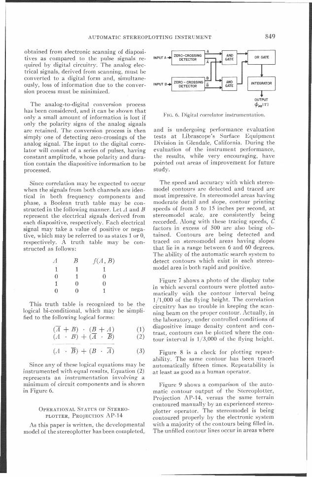
The analog-to-digital conversion processhas been considered, and it can be shown thatonly a small amount of information is lost ifonly the polarity signs of the analog signalsare retained. The conversion process is thensimply one of detecting zero-crossings of theanalog signal. The input to the digital correlator will consist of a series of pulses, havingconstant amplitude, whose polarity and duration contain the diapositive information to beprocessed.
OUTPUT
epAOI T)
FIG. 6. Digital correIa tor instrumentation.
and is undergoing performance evaluationtests at Librascope's Surface EquipmentDivision in Glendale, California. During theevaluation of the instrument performance,the resul ts, while very encouraging, havepointed out areas of improvement for futurestudy.
(A+B) (B+A) (1)(A B) + (A B) (2)
This truth table is recognized to be thelogical bi-conditional, which may be simplified to the following logical forms:
Since correlation may be expected to occurwhen the signals from both channels are identical in both frequency components andphase, a Boolean truth table may be constructed in the following manner. Let A and Brepresent the electrical signals derived fromeach diapositive, respectively. Each electricalsignal may take a value of positive or negative, which may be referred to as states 1 or 0,respectively. A truth table may be constructed as follows:
A1o1o
B11oo
l(A, B)1oo1
The speed and accuracy with which stereomodel contours are detected and traced aremost impressive. In stereomodel areas havingmoderate detail and slope, contour printingspeeds of from 5 to 15 inches per second, atstereomodel scale, are consistently beingrecorded. Along with these tracing speeds, Cfactors in excess of 500 are also being obtained. Contours are being detected andtraced on stereomodel areas having slopesthat lie in a range between 6 and 60 degrees.The ability of the automatic search system todetect con tours which exist in each stereomodel area is both rapid and positive.
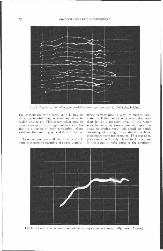
Figure 7 shows a photo of the display tubein which several contours were plotted automatically with the contour interval beingJ/1,000 of the flying height. The correlationcircuitry has no trouble in keeping the scanning beam on the proper contour. Actually, inthe laboratory, under controlled conditions ofdiapositive image density content and contrast, con tours can be plotted where the contour interval is 1/3,000 of the flying height.
OPERATIONAL STATUS OF STEREO
PLOTTER, PROJECTIO AP-14
As this paper is written, the developmentalmodel of the stereoplotter has been com pleted,
Since any of these logical equations may beinstrumented with equal results, Equation (2)represents an instrumentation involving aminimum of circuit components and is shownin Figure 6.
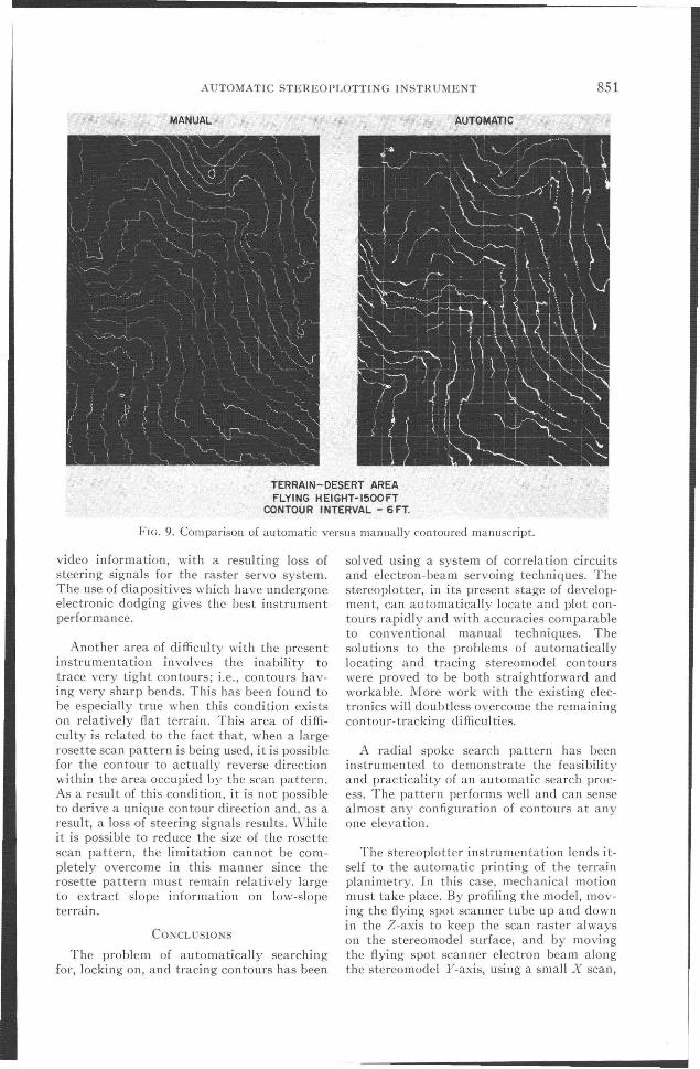
(A B) +(B A) (3) Figure 8 is a check for plotting repeatability. The same contour has been tracedautomatically fifteen times. Repeatability isat least as good as a human operator.
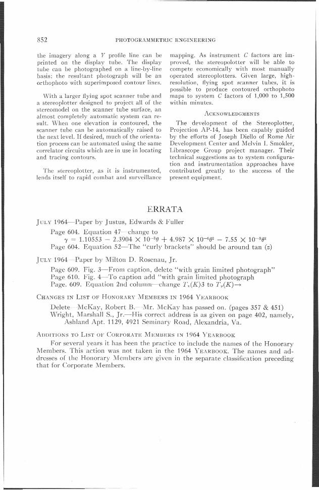
Figure 9 shows a comparison of the automatic contour output of the Stereoplotter,Projection AP-14, versus the same terraincontoured manually by an experienced stereoplotter operator. The stereomodel is bei ngcontoured properly by the electronic systemwith a majority of the contours being filled in.The unfilled contour lines occur in areas where
850 PHOTOGRAMMETRIC ENGINEERING
FIG. 7. Demonstration of system sensitivity (contour interval = 1/1,000 flying height).
the contour-following servo loop is havingdifficulty in obtaining an error signal as towhich way to go. This occurs when movingalong a contour from a region of good correlation to a region of poor correlation. Morework on the circuitry is needed in this area.
As is common with all instruments whichemploy electronic scanning of stereo diaposi-
tives, performance is very intimately associated with the particular type of detail resident in the diapositive areas of the rasterscan. In particular, the scanning of diapositiveareas containing very little detail, or detailconsisting of a single gray shade, result inpoor instrument performance. This degradedperformance is directly related to the decreasein the signal-to-noise ratio of the resultant
FIG. 8. Demonstration of system repeatability (single contour automatically traced 15 times).
AUTOMATIC STEREOPLOTTING INSTRUMENT 851
MANUAL AUTOMATIC
TERRAIN-DESERT AREAFLYING HEIGHT-1500FT
CONTOUR INTERVAL - 6FT.
FIG. 9. Comparison of automatic versus manually contoured manuscript.
video information, with a resulting loss ofst~ering signals for the raster servo system.The use of diapositives which have undergoneelectronic dodging gives the best instrumentperformance.
Another area of di fficul ty with the presen tinstrumentation involves the inability totrace very tight contours; i.e., contours having very sharp bends. This has been found tobe especially true when this condition existson relatively flat terrain. This area of difficulty is related to the fact that, when a largerosette scan pattern is being used, it is possiblefor the contour to actually reverse directionwithin the area occupied by the scan pattern.As a result of this condition, it is not possibleto derive a unique contour direction and, as aresult, a loss of steering signals results. Whileit is possible to reduce the size of the rosettescan pattern, the limitation cannot be completely overcome in this manner since therosette pattern must remain relatively largeto extract slope information on low-slopeterrain.
CONCLUSIONS
The problem of automatically searchingfor, locking on, and tracing contours has been
solved using a system of correlation circuitsand electron-beam servoing techniques. Thestereoplotter, in its present stage of development, can automatically locate and plot contours rapidly and with accuracies comparableto conventional manual techniques. Thesolutions to the problems of automaticallylocating and tracing stereomodel contourswere proved to be both straightforward andworkable. More work with the existing electronics will doubtless overcome the remainingcon tour- tracking di fficul ties.
A radial spoke search pattern has beeninstrumented to demonstrate the feasibilityand practicality of an automatic search process. The pattern performs well and can sensealmost any configuration of contours at anyone elevation.
The stereoplotter instrumen ta tion lends itself to the automatic printing of the terrainplanimetry. In this case, mechanical motionmust take place. By profiling the model, moving the flying spot scanner tube up and downin the Z-axis to keep the scan raster alwayson the stereomodel surface, and by movingthe flying spot scanner electron beam alongthe stereomodel Y-axis, using a small X scan,
852 PHOTOGRAMMETRIC ENGINEERING
the imagery along a Y profile line can beprinted on the display tube. The displaytube can be photographed on a line-by-linebasis; the resultant photograph will be anorthophoto with superimposed contour lines.
With a larger flying spot scanner tube anda stereoplotter designed to project all of thestereomodel on the scanner tube surface, analmost completely automatic system can resui t. When one elevation is contoured, thescanner tube can be automatically raised tothe next level. If desired, much of the orientation process can be automated using the samecorrelator circuits which are in use in locatingand tracing contours.
The stereoplotter, as it is instrumented,lends itself to rapid combat and surveillance
mapping. As instrument C factors are improved, the stereopolotter will be able tocompete economically with most manuallyoperated stereoplotters. Given large, highresolution, flying spot scanner tubes, it ispossible to produce contoured orthophotomaps to system C factors of 1,000 to 1,500within minutes.
ACKNOWLEDGMENTS
The development of the Stereoplotter,Projection AP-14, has been capably guidedby the efforts of Joseph Diello of Rome AirDevelopment Center and Melvin I. Smokier,Librascope Group project manager. Theirtechnical suggestions as to system configuration and instrumentation approaches havecontributed greatly to the success of thepresent equipment.
ERRATAJULY 1964-Paper by Justus, Edwards & Fuller
Page 604. Equation 47-change to"y = 1.10553 - 2.3904 X 10⁻³⁰ + 4.987 X 10-602 - 7.55 X 10-903
Page 604. Equation 52-The "curly brackets" should be around tan (z)
JULY 1964-Paper by Milton D. Rosenau, Jr.
Page 609. Fig. 3-From caption, delete "with grain limited photograph"Page 610. Fig. 4-To caption add "with grain limited photographPage. 609. Equation 2nd column-change T v(K)3 to Tv(K)~
CHANGES IN LIST OF HONORARY MEMBERS IN 1964 YEARBOOK
Delete-McKay, Robert B.-Mr. McKay has passed on. (pages 357 & 451)Wright, Marshall S., Jr.-His correct address is as given on page 402, namely,
Ashland Apt. 1129,4921 Seminary Road, Alexandria, Va.
ADDITIONS TO LIST OF CORPORATE MEMBERS IN 1964 YEARBOOK
For several years it has been the practice to include the names of the HonoraryMembers. This action was not taken in the 1964 YEARBOOK. The names and addresses of the Honorary Members are given in the separate classification precedingthat for Corporate Members.