a high voltage system with 60 high voltage power supply channels in 2u height euro crate masatosi...
TRANSCRIPT

A High Voltage System with 60 High Voltage Power Supply Channels
in 2U Height EURO Crate
Masatosi IMORI, Nagataka Matsui, Masaya ISHINO, Toshiyuki Kimura1, Tomoharu Mieno1, Satoru Imada1 and Masafu
mi Katsuno2
International Center for Elementary Particle Physics, University of Tokyo7-3-1 Hongo, Bunkyo-ku, Tokyo 113-0033, Japan
1NF Corporation, 6-3-20 Tsunashima Higashi, Kohoku-ku, Yokohama-shi 223-8508, Japan
2NEC TOKIN Corporation, 7-1, Kohriyama 6-chome, Taihaku-ku, Sendai-shi, 982-8510, Japan
The High Voltage System
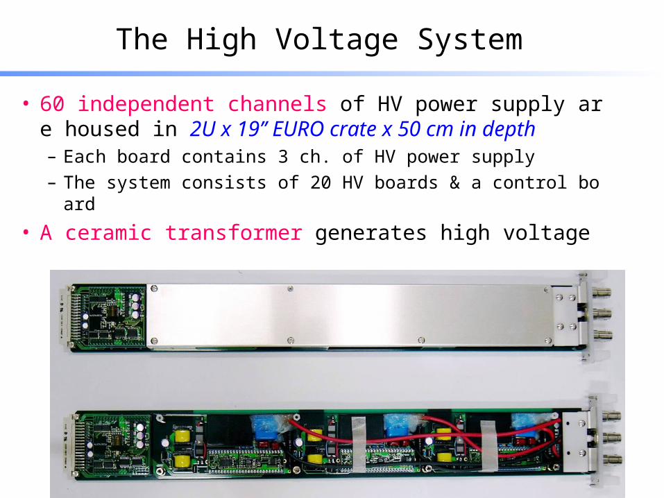
• 60 independent channels of HV power supply are housed in 2U x 19’’ EURO crate x 50 cm in depth– Each board contains 3 ch. of HV power supply
– The system consists of 20 HV boards & a control board
• A ceramic transformer generates high voltage

generation of HV by Ceramic Transformer (CT)
• HV is generated by piezoceramic effect– CT is made of ceramic bar
– CT contains no magnetic material
operational under magnetic field
• rating 5W
• resonance frequency ~ 150 kHz
• input voltage > 6 V
• efficiency 95 %
• amplitude ratio > 120
• output voltage > 707 V

amplitude ratio vs driving frequency
• carrier wave is supplied to CT and it’s amplified by internal resonance circuit of CT
• The amplitude ratio is a function of the driving frequency of carrier wave
of carrier wave
~ 150kHz
control HV = control frequency of carrier wave

The High Voltage System
• output capability– each channel supplies stabilized HV up to 4 kV to load more than 20
Mega ohm ( ~200 micro-Amp. )
• magnetic field tolerance– we confirmed it’s operational under the magnetic field of 1-Tesla
• Radiation Hardness– 60 MeV protons ; 1E11 (~14krad) [tested at PIF @ PSI ]
– Cobalt-60 gamma-ray ; ~300krad
the system cope with both conditions

The High Voltage System (cont’d)

HV control and monitoring system
• The HV power supply is controlled by external computer via USB interface (chosen for general purpose application)
– GUI based software for Windows OS
– CUI based software for Linux OS
are developed
• as a basic functionality– individual channel can be turned on and off
– output voltage can be set
– output current can be monitored

current monitoring system & chamber spark
• Each HV board has 9 bit A/D converter (CS5523)– output current is monitored with a sampling rate of 80Hz (12.5 msec)
• there are two operation modes
• This sampling rate and resolution of current monitor allows us to detect “spark” happened in chamber because of neutron.
mode full scale precision
maintenance 10 micro A 20 nA
operation 250 micro A 500 nA
leak current monitoring for chamber conditioning
working mode under particle flux
time
current
100 msec
10 micro Amp

over current shutdown
• more over, basic functionality like– turns off power supply, if output current keeps larger than a setting threshold
during a prescribed time interval (tsec)
is implemented
• This process is implemented in FPGA (anti-fuse type , mounted on each HV board) by hard-wired logic.– no software is necessary
• The system can be operated safely and can be applied to a delicate object like wire chamber, … etc

output current and return current
• The output current is measured by the return current
• The voltage caused by the return current across the sense resister is amplified and digitized by A/D converter.

next revision in progress
• Four terminal ceramic transformer– Tokin Corp. develops four terminal ceramic transformer
dedicated to the high voltage power supply
A
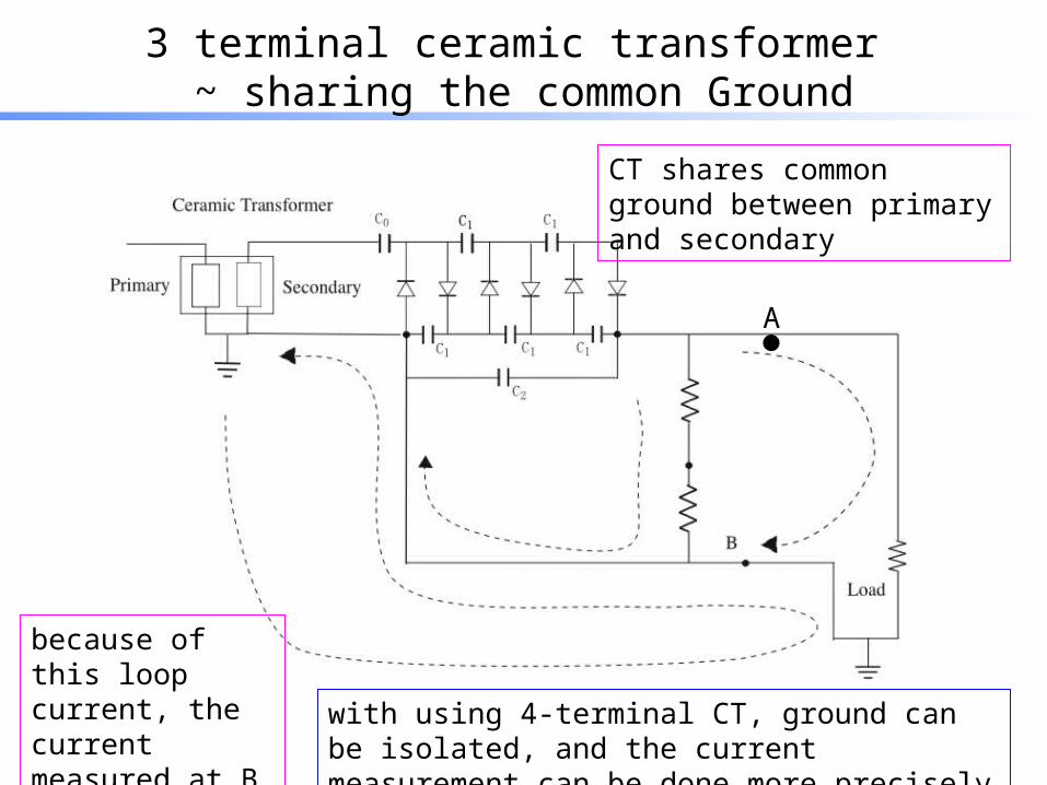
3 terminal ceramic transformer ~ sharing the common Ground
A
because of this loop current, the current measured at B is not always the one at A
CT shares common ground between primary and secondary
with using 4-terminal CT, ground can be isolated, and the current measurement can be done more precisely

summary
• The HV power supply of 60 channels housed in 2U x 19’’ x 50cm is fabricated
• Ceramic transformer is used for generating HV– magnetic field tolerant (1Tesla)
• Radiation hardness– 60 MeV protons ; 1E11 (~14krad)
– Cobalt-60 gamma-ray ; ~300krad
• output current monitoring– important for the operation of delicate object like wire chamber
– current monitoring with a frequency of 80Hz• for the detection of the chamber spark signal
• next version is in progress– four terminal Ceramic Transformer will be used to improve output current
monitoring

Elimination of 3.5 V
• So far the ceramic transformer employed in the power supply is driven by the driver circuit which is powered by 3.5 V.
• The dedicated transformer is driven by the driver circuit powered by 48 V.
• The high voltage power supply employing the dedicated transformer eliminates the power supply of 3.5 V, which simplifies supply voltages to +/- 5 V and 48 V.

Stabilization of Output Voltage