a honeybee's navigational toolkit on board a bio-inspired ... · a honeybee's...
TRANSCRIPT

A honeybee’s navigational toolkit on Board aBio-inspired Micro Flying Robot
Erik Vanhoutte, Franck Ruffier and Julien Serres ∗
Aix-Marseille Univ, CNRS, ISM, Marseille, France
ABSTRACT
In this paper, a 395-gram micro flying robotequipped with an insect-inspired visual systemis presented. The robot’s visual system was de-signed to make it avoid both ground and lat-eral obstacles, using optic flow-based regulationprinciples. The quadrotor is an open-hardwareX4-MaG drone with an active gimbal systembased on a pair of serial servo motors, which sta-bilizes 8 retinas dedicated to optic flow measure-ments in the 25 ◦/s to 1000 ◦/s range, each ofwhich comprises 12 auto-adaptive pixels work-ing in a 7-decade lighting range. The X4-MaGdrone is tested in front of a slanted wall, its quasi-panoramic bio-inspired eye on board is able toestimate the angle of incidence in the 0◦ to 50◦
range with an error of less than 2.5◦ when fly-ing. These experimental results are a first steptowards a fully autonomous micro quadrotor re-quiring no magnetometers, which will be able inthe near future to “sense and avoid” obstacles inGPS-denied environments.
16 cm
Figure 1: Photograph of the X4-MaG quadrotor with the gimbalcase attached below (total mass: 395 g, span: 30 cm, autonomy: 6min).
∗Correspondance: [email protected]; Tel.: +33(0)4 91 26 62 38
1 INTRODUCTION
Mimicking the flight of a tiny honeybee is still an ardu-ous task [1, 2]. Since insect-sized micro air vehicles are in-creasingly becoming reality, however, [3, 4, 5, 6] it will benecessary to endow them in the future with sensors and flightcontrol devices enabling them to perform all kinds of aerialmaneuvers, including ground and obstacle avoidance, terrain-following and landing, in the same way as honeybees. This isa difficult challenge in the field of robotics, although dronescan now be miniaturized thanks to recent advances in embed-ded electronics.
Stereovision-based strategies on board micro flyingrobots have recently provided means of exploring and avoid-ing obstacles indoors, but only under slow flight conditions[7, 8]. Micro LiDAR ( Light Detection And Ranging devices)are also available for micro air vehicle applications (e.g.,Centeye Inc. in the USA or LeddarTech Inc. in Canada),but these devices require a scanning system and have a highenergy consumption. The optic flow (OF) is also a relevantvisual cue which can be used for quickly sensing the con-figuration of the environment using either micro cameras orcustom-made OF sensors.
Unfortunately, micro cameras sample tens of thousandsof pixels with a refresh rate of only about 30 frames per sec-ond [9, 10], which is 10 times lower than the temporal res-olution of the bees eye (∼ 300 Hz, see [1]), and they alsorequire much more computational resources than custom-made OF sensors. In addition, micro cameras are blindedby the changes in the light which occur when moving fromone room to another, from indoor to outdoor conditions, orwhen encountering strong sunny to shadow contrasts. How-ever, custom-made OF sensors lighten both the weight and theCPU load of micro flying robots , and enable them to makequasi panoramic OF measurements [11, 12, 13] as well asto work under various unpredictable lighting conditions. Be-cause of their lack of visual stabilization, micro flying robotshave to fly at low speeds despite the use of OF regulation prin-ciples [14, 10]. Up to now, no OF sensing strategies based ona stabilization system preventing the rotational effects haveyet been implemented on board a micro flying robot.
In [9], the slope of the ground was assessed on board aquadrotor. In [15], 10 local OF measurements coupled to aleast mean squares method were used to stabilize a minimal-istic quasi-panoramic compound eye on the Beerotor robotwith respect to the local downward slope, thus enabling therobot to avoid any very steep relief encountered. In [16], an
136 International Micro Air Vehicle Conference and Flight Competition (IMAV) 2017

Gimbals OctoM2APix
M²APix a12 pixels
M²APix b12 pixels
M²APix c12 pixels
M²APix d12 pixels
M²APix e12 pixels
M²APix f12 pixels
M²APix g12 pixels
M²APix h12 pixels
Servo motor pitchMKS 480
Servo motor rollMKS 480
SPI
PWM
PWMU
ART
@3 M
bps
IMUMPU-6050
XRA1404
Teensy
@1 Mbps
SPI
@26 M
bpsI2
C
Overo AirSTORM (Gumstix)1 GHz Cortex-A8, 512 Mb RAM
NanoWii16 MHz ATmega32u4
UART
T-Motor MT1306 & 5030 props
IMU 6 DOFMPU-6050
T-Motor MT1306 & 5030 props
T-Motor MT1306 & 5030 props
T-Motor MT1306 & 5030 props
PWMWiFi
SPI @1 Mbps
an ... a2 a1M²APix a
cn ... c2 c1
bn...b2b1
dn...d2d1
fn...f2f1
hn...h2h1
en ... e2 e1
gn ... g2 g1
XRA 1404
Teensy
SPI @26 Mbps
ComputationalUnit
UART @3 Mbps
bi
ai
ci
diei
figi
hi
M²APix c
M²APix e
M²APix g
M²APix b
M²APix d
M²APix f
M²APix h
bn
an
cn
dnen
fngn
hn
b1a1 c1 d1e1 f1 g1 h1 ...
an ... a1hn... h1 gn ... g1 bn
... b1...
1
2
3
a) b)
1
2
3
Overo AirSTORM (Gumstix)
1 GHz Cortex-A8, 512 Mb RAM
Figure 2: a) Component architecture of the X4-MaG quadrotor with the gimbal elements surrounded by a dash-dot line. The developmentboards and the data transmission units are shown in gray, the actuators in blue, and the sensors in yellow. b) Data diagram of how visualsignals originating from the OctoM2APix eye are processed: 1 high speed synchronous data capture, 2 data put in order, and 3 signalprocessing for optic flow computations.
innovative OF-based algorithm was tested in the horizontalplane as a means of measuring the robot’s incidence anglewhen perceiving a slanting wall showing a moving texture.The results of our experiments showed that our minimalis-tic algorithm based on 20 local OF measurements could beused to determine the local visual heading with respect to themoving slanting wall with an error of less than 3◦ and a meanaccuracy of 3◦ [16].
In the present paper, a bio-inspired micro flying robot,which will be able to perform both wall-following andground-avoidance tasks in GPS-denied (Global PositioningSystem-denied) environments. This robot is fitted with a vi-sual stabilization system involving 8 custom-made OF sen-sors which can respond appropriately in a 7-decade lightingrange [17] and can measure the OF magnitude from 25 ◦/s to1000 ◦/s [18]. It was established in real flight tests that thismicro flying robot is able to estimate its incidence angle withrespect to a slanting wall in order to restore its flight parallelto the wall. The results obtained in the present study showthat our quasi-panoramic bio-inspired eye coupled to a com-putational unit can estimate this incidence angle in the 0◦ to50◦ range when flying.
2 MICRO FLYING ROBOT
The micro flying robot presented here, a 320-gramquadrotor that can carry a maximum payload of 90 g, is basedon the open-hardware X4-MaG model [19]. Thanks to anopen-source Matlab/Simulink toolbox [20], it is possible to
monitor this quadrotor in real time by wifi and change therelevant parameters directly during its flight. We have addedto this quadrotor a custom-made 3D print gimbal case en-dowed with a magnet-based system of fixation facilitating itsremoval. This custom-made gimbal stabilizes the 8 OF sen-sors on the pitch and roll axes via two 10-gram serial servomotors (Fig. 1). The first group of 3 OF sensors oriented tothe left measure a left OF, the second group of 3 sensors ori-ented to the right measure a right OF: each of these groups hasa field of view of 92.8◦ in the horizontal plane and 13.4◦ inthe vertical plane. The third group of two downward-orientedsensors measure the ventral OF with a field of view of 62.8◦
in the forward axis and 13.4◦ in the orthogonal axis. The gim-bal system, which is stabilised in attitude during the robot’sflight, has a total mass of 75 grams enabling the robot to flyfor 6 minutes.
The quadrotor is fitted with a low-level autopilot basedon the Nanowii (ATmega32u4, MultiWii) with a 6 degrees offreedom Inertial Measurement Unit (IMU) (Fig. 2a). Thislow-level control board makes it possible for the robot to bepiloted manually and takes over from the Gumstix if failure ofthe latter occurs. All attitude and trajectory control processesbased on the OF measurements are handled by the high-level autopilot based on an Overo AirSTORM Computer-On-Module (COM) (Gumstix) featuring a 1-GHz CPU DM3703processor (Texas Instruments) comprising an ARM Cortex-A8 architecture. A Teensy 3.2 featuring a 72 MHz Cortex-M4 (PJRC) controls the gimbal servo motors and also reads
International Micro Air Vehicle Conference and Flight Competition (IMAV) 2017 137

the 8 retinas (dedicated to OF measurements) and transmitsthe pixel data to the Overo AirSTORM (Fig. 2a, for details).
3 OPTIC FLOW SENSORS
The M2APix sensor is a bio-inspired OF sensor based ona Michaelis-Menten Auto-adaptive Pixel analog silicon retinathat can auto-adapt in a 7-decade lighting range and respondsappropriately to stepwise changes of up to ± 3 decades [17].Each M2APix sensor is composed of 12 pixels distributed intwo rows of six pixels offset by half the interpixel distance[17], and is able to make 10 local OF measurements with ahigh output refresh rate [18]. The local OF is measured us-ing a time-of-travel algorithm based on a contrast detectionmatching method (called the thresholding method) running atonly 1 kHz along the pixels rows axis.
The CPU load of the Overo AirSTORM is less than 3percent per M2APix sensor and the OF refresh rate is up to99 Hz per M2APix sensor with an OF ranging from 25 ◦/s to1000 ◦/s [18].
4 A GIMBAL SYSTEM NAMED OCTOM2APIX
A custom-made PCB was designed for the gimbal sys-tem named OctoM2APixto connect the following compo-nents (Fig. 2a): a Teensy 3.2 featuring a 72 MHz Cortex-M4(PJRC), an 8-bit SPI GPIO EXPANDER called XRA1404(Exar c©), an Inertial Measurement Unit (IMU) MPU 6050,and connections to 8 M2APix sensors and 2 servo motors be-longing to the gimbal system, in order to stabilize the bio-inspired eye on the pitch and roll axes and thus remove anyrotational OF components.
A M2APix sensor works with a SPI bus running at a max-imum rate of 1 MHz, which transmits a 256-bit data frame,and the maximum theoretical frame rate is therefore 3906 Hz.SPI devices communicate in the full duplex mode using amaster-slave architecture with a single master. Only one SPIbus is usually available on dedicated electronic boards. Themaximum frame rate possible to obtain data from the 8 slaveM2APix sensors is therefore less than 488 Hz, and the datawill not be processed synchronously but sequentially (Fig.2b). To give from the 8 M2APix sensors higher frame ratesand make the processing synchronous, a XRA1404 GPIOEXPANDER was used. The XRA1404 can read the logicstate on 8 digital ports and send this data as a byte to an SPIbus working at a frequency of 26 MHz (Fig. 2b). Each ofthese 8 digital ports is used to read the bit to bit data frameof each M2APix sensor (step 1 in the Fig. 2b). As a re-sult, the first bit in all the M2APix data frames are arrangedin one byte, which is sent on to the SPI bus. Each bit in eachM2APix sensor is processed in this way.
The Teensy electronic board reads the SPI bus at a fre-quency of 26 MHz from the XRA1404 and puts each dataframe of each M2APix sensor back into order (step 2 in Fig.2b). The M2APix sensor sends a mean light value and 12pixel values, each of which is coded in 10-bit values. The al-
gorithm then selects only the pixel data. This leaves us with12x10 bits per M2APix sensor . Lastly, the Teensy removesthe offset of the range used and deletes the last bit which isequivalent to the amplitude of the noise, to express the datain the 8-bit format. The 12 pixels coded with the 8-bit valueof the 8 M2APix sensors are then sent to the serial bus at aspeed of 3 Mbps to a computational unit to compute the OF(step 3 shown in Fig. 2b).
5 FLYING STRATEGIES
The OctoM2APix is designed to make the X4-MaG droneboth follow walls and adjust its height at relatively highspeeds (up to 2.5 m · s−1) by removing the rotational OFcomponent of the sensing performed by the 8 M2APix sen-sors. Wall-following and ground-following behaviour will beobtained by merging OF regulation principles [21]. The aimof the flying strategies we propose to pursue in the near futurewill be to maintain the visual contact with the walls in orderto make the robot fly in parallel along one of them. Thesestrategies will involve adding another visual feedback loopcontrolling the yaw component by estimating the relative lo-cal angle between the nearest wall (e.g., the red rectangle inFig. 4a) and the flying robot. Figure 3 and Eq. 1 explain howto obtain this incidence angle α from OF measurements witha very light solution in terms of the computational resourcesrequired, where c is cos, s is sin, and t is the tan function.
BD
E
Wall
D
F
O
B
123
Figure 3: Geometry of the OctoM2APix eye (centring in O) onthe horizontal plane with a tapered wall on its left-hand side. Eachgreen rectangle represents one M2APix sensor. In the left-hand side,the M2APix are numbered to make the experiments easier to under-stand.
ωB =V
OB· s(ϕB) ωD =
V
OD· s(ϕD)
t(α) =OD · s(ϕD)−OB · s(ϕB)OB · c(ϕD)−OD · c(ϕB)
t(α) =
1ωD· s(ϕD)2 − 1
ωB· s(ϕB)2
1ωB· s(ϕB) · c(ϕB)− 1
ωD· s(ϕD) · c(ϕD)
α = t−1
(ωB · s(ϕD)2 − ωD · s(ϕB)2
ωD · s(ϕB) · c(ϕB)− ωB · s(ϕD) · c(ϕD)
)(1)
138 International Micro Air Vehicle Conference and Flight Competition (IMAV) 2017

20° Trajectory
Pattern
Pattern
Trajectoryangle
0°
50°
10°
20°
30°
40°
End point
a) b)
Figure 4: a) Chronophotograph of the X4-MaG drone at the Mediterranean Flying Arena. The flying robot followed a textured ”wall”sloping at an angle of 20◦ for about 4.5 s (corresponding to one of the blue trajectories in b). b) Top view of all the trajectories taken inthe Mediterranean Flying Arena1. 6 different trajectories were tested at the same height (0.8 m ± 0.01 m) with a clockwise angle betweenthe trajectories and the patterned wall. The X4-MaG drone followed each trajectory several times. Depending on the angle of the trajectory,either M2APix #3 or both M2APix #2 & #3 did not perceive the pattern on the wall due to their orientation (their positions are given by adashed line and a dotted line, respectively).
6 FLYING EXPERIMENT
Figure 5: Speed profile (in XY plane) of the aerial robot for all thetrajectories presented in Fig. 4b. µ is the mean value and σ is thestandard deviation.
This flight experiment consisted in observing the dynamicresponses of the OctoM2APix sensor with all the compo-nents integrated during real flight. The X4-MaG flying atthe Mediterranean Flying Arena1 (6x8x6 m): its trajectorywas controlled in the closed loop mode with a motion capturesystem (VICONTM). A 4-m long wall covered with a natural
1http://flying-arena.eu/
pattern was hanging in the arena to generate OF when the X4-MaG approached it. The X4-MaG repeated various straighttrajectories 6 times at the same height (0.8 m ± 0.01 m) withthe pattern on the right-hand side and with an angle of inci-dence α between its trajectory and the pattern ranging from0◦ to 50◦ in 10◦ steps (Fig. 4). The three M2APix sensorscould therefore potentially detect the pattern and measure theOF during the experiments.
To test the case of future aggressive maneuvers in an in-door environment, the flights were then performed at highspeed (up to 2.5 m · s−1, see Fig. 5) near obstacles (witha clearance of up to 0.5 m, see Fig. 4). The figure 5 gives thespeed profiles of all the trajectories including one high ac-celeration (up to 6 m · s−2) phase and one high decelerationphase.
The figure 4b presents all the trajectories tracked. Due tothe flying robots proximity with the patterned wall, aerody-namic perturbations were generated at the end of the trajec-tories, during the last metre (Fig. 4b). During a part of thetrajectories from 10◦ to 50◦ shown by a dashed line, the pat-tern was not visible to the M2APix #3 (oriented at an angle of120◦ in Fig. 3) , and the dotted lines indicate the part of thetrajectories where the pattern was not visible to the M2APix#2 (oriented at an angle of 90◦ in Fig. 3). None of the OFmeasurements obtained during these dashed and dotted partsof the trajectories were included in the following statisticalanalyses.
A median filter was applied to the 10 local OF measure-ments obtained by each M2APix sensor, and the M2APix out-
International Micro Air Vehicle Conference and Flight Competition (IMAV) 2017 139
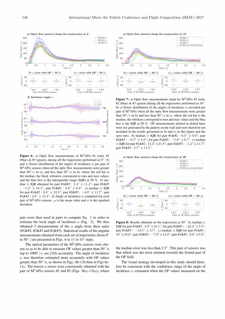
Figure 6: a) Optic flow measurements of M2APix #1 (red), #2(blue) & #3 (green), during all the trajectories performed at 0◦. b)and c) Errors distribution of the angles of incidence α per pair ofM2APix sensors when all the optic flow measurements were greaterthan 50◦/s in c), and less than 50◦/s in d), where the red bar isthe median, the black whiskers correspond to min and max values,and the blue box is the interquartile range (IQR) at 50 %. b) me-dian ± IQR obtained for pair #1 : 2.4◦ ± 11.4◦; pair #2: −1.2◦ ± 10.1◦; pair #1 : 0.0◦ ± 6.8◦. c) median ± IQRfor pair #1 : 8.8◦ ± 24.5◦; pair #2 : −4.0◦ ± 11.7◦; pair#1 : 2.6◦ ± 13.4◦. d) Angle of incidence α computed for eachpair of M2APix sensors. µ is the mean value and σ is the standarddeviation.
puts were then used in pairs to compute Eq. 1 in order toestimate the local angle of incidence α (Fig. 3). We thusobtained 3 measurements of the α angle from these pairs(#1, #2 and #1). Statistical results of the angularmeasurements obtained from each set of trajectories (from 0◦
to 50◦ ) are presented in Figs. 6 to 11 in 10◦ steps.The optical parameters of the M2APix sensors were cho-
sen so as to be able to measure OF values greater than 50◦ /s(up to 1000◦/s, see [18]) accurately. The angle of incidenceα was therefore estimated more accurately with OF valuesgreater than 50◦ /s, as shown in Figs. 6b-11b than in Figs 6c-11c. The lowest α errors were consistently obtained with thepair of M2APix sensors #1 and #2 (Figs. 6b,c-11b,c), where
0 0.5 1 1.5 2 2.5 3 3.5 4 4.5time [s]
0
50
100
150
200
250
Optic
Flo
w[/=s]
a) Optic .ow pattern along the trajectories at 10/
M2APix 1M2APix 2M2APix 3M2APix not facing Pattern
1 & 2 2 & 3 1 & 3Pair of M2APix sensors
-50
0
50
,Err
or
[/]
b) , error with OF > 50//s
1 & 2 2 & 3 1 & 3Pair of M2APix sensors
-50
0
50
,Err
or
[/]
c) , error with OF < 50//s
Figure 7: a) Optic flow measurements made by M2APix #1 (red),#2 (blue) & #3 (green) during all the trajectories performed at 10◦.b) c) Errors distribution of the angles of incidence α recorded perpair of M2APix when all the optic flow measurements were greaterthan 50◦/s in b) and less than 50◦/s in c), where the red bar is themedian, the whiskers correspond to min and max values and the bluebox is the IQR at 50 %. OF measurements plotted in dotted lineswere not generated by the pattern on the wall and were therefore notincluded in the results presented in b) and c) in this figure and thenext ones. b) median ± IQR for pair #1 : 0.5◦ ± 9.6◦; pair#2 : −8.7◦ ± 9.8◦; for pair #1 : −5.6◦ ± 6.7◦. c) median± IQR for pair #1 : 12.3◦±21.8◦; pair #2 : −1.2◦±11.7◦;pair #1 : 5.7◦ ± 11.5◦.
0 0.5 1 1.5 2 2.5 3 3.5 4 4.5time [s]
0
50
100
150
200
250
Optic
Flo
w[/=s]
a) Optic .ow pattern along the trajectories at 20/
M2APix 1M2APix 2M2APix 3M2APix not facing Pattern
1 & 2 2 & 3 1 & 3Pair of M2APix sensors
-50
0
50
,Err
or
[/]
b) , error with OF > 50//s
1 & 2 2 & 3 1 & 3Pair of M2APix sensors
-50
0
50
,Err
or
[/]
c) , error with OF < 50//s
Figure 8: Results obtained on the trajectories at 20◦. b) median ±IQR for pair #1 : 2.0◦±10.1◦; for pair #2 : −22.4◦±7.6◦;pair #1 : −12.5◦ ± 3.7◦. c) median ± IQR for pair #1 :10◦±16.6◦; pair #2 : −7.9◦±12.0◦; pair #1 : 0.6◦±9.9◦.
the median error was less than 2.5◦. This pair of sensors wasthat which was the most oriented towards the frontal part ofthe OF field.
The visual strategy developed in this study should there-fore be consistent with the confidence range of the angle ofincidence α estimated when the OF values measured on the
140 International Micro Air Vehicle Conference and Flight Competition (IMAV) 2017

0 0.5 1 1.5 2 2.5 3 3.5 4 4.5time [s]
0
50
100
150
200
250
Optic
Flo
w[/=s]
a) Optic .ow pattern along the trajectories at 30/
M2APix 1M2APix 2M2APix 3M2APix not facing Pattern
1 & 2 2 & 3 1 & 3Pair of M2APix sensors
-50
0
50
,Err
or
[/]
b) , error with OF > 50//s
1 & 2 2 & 3 1 & 3Pair of M2APix sensors
-50
0
50
,Err
or
[/]
c) , error with OF < 50//s
Figure 9: Results obtained on the trajectories 30◦. The M2APix 3did not measure optic flows greater than 50◦/s, which explains thelack of results on the pair of M2APix #2 and #1 in b). b)median ± IQR for pair #1 : −2.3◦ ± 6.0◦. c) median ± IQRfor pair #1 : 6.9◦ ± 13.4◦; pair #2 : −9.1◦ ± 23.0◦; pair#1 : −3.5◦ ± 8.5◦.
0 0.5 1 1.5 2 2.5 3 3.5 4time [s]
0
50
100
150
200
250
Optic
Flo
w[/=s]
a) Optic .ow pattern along the trajectories at 40/
M2APix 1M2APix 2M2APix 3M2APix not facing Pattern
1 & 2 2 & 3 1 & 3Pair of M2APix sensors
-50
0
50
,Err
or
[/]
b) , error with OF > 50//s
1 & 2 2 & 3 1 & 3Pair of M2APix sensors
-50
0
50
,Err
or
[/]
c) , error with OF < 50//s
Figure 10: Results obtained on the trajectories 40◦. b) median ±IQR for pair #1 : −2.5◦ ± 4.1◦. c) median ± IQR for pair#1 : −3.4◦ ± 10.7◦; pair #2 : −7.9◦ ± 17.5◦; pair #1: −6.0◦ ± 13.8◦.
micro aerial vehicle were high, i.e. at high speeds, as wellas when the micro aerial vehicle was travelling very near thewalls.
7 CONCLUSION
The 395-gram X4-MaG quadrotor fitted with a gimbalsystem and a set of 8 custom-made optic flow sensors pro-vides an appropriate flying platform for testing optic-flowregulation principles during real flight with a view to mim-icking honeybees’ flight performances. The gimbal sys-tem makes it possible to minimize the effects of the rota-tional component of the optic flow measured by the quasi-panoramic bio-inspired eye. The results obtained in these ex-
0 0.5 1 1.5 2 2.5 3 3.5 4time [s]
0
50
100
150
200
250
Optic
Flo
w[/=s]
a) Optic .ow pattern along the trajectories at 50/
M2APix 1M2APix 2M2APix 3M2APix not facing Pattern
1 & 2 2 & 3 1 & 3Pair of M2APix sensors
-50
0
50
,Err
or
[/]
b) , error with OF > 50//s
1 & 2 2 & 3 1 & 3Pair of M2APix sensors
-50
0
50
,Err
or
[/]
c) , error with OF < 50//s
Figure 11: Results obtained on the trajectories at 50◦. The patternon the wall was not visible to M2APix #3 during all these trajecto-ries, which explains the lack of data on the pair of M2APix #2and #1 in c). c) median± IQR for pair #1 : −3.1◦±15.8◦.
periments show that our optic flow based algorithm can es-timate the drone’s local angle of incidence with respect to aslanting wall in the 0◦ to 50◦ range during flight with an errorof less than 2.5◦, using the optic flow generated on either side(left or right). To measure larger angles of incidence (from50◦ to 90◦), the fronto-bilateral optic flow could be used inthe similar way to that simulated in [22], but this possibilityis beyond the scope of the present study and would requiremeasuring the low optic flow values occurring close to thefocus of expansion.
In the near future, flying at high speed (up to 1 m/s)near obstacles (at a distance of less than 0.5 m) may be pos-sible thanks to the large range of optic flow measurementswhich can now be made, namely up to 1000◦/s. The ad-vantages of the custom-made optic flow sensors used hereinclude low power consumption, low computational require-ments, and robustness to high dynamic range lighting condi-tions (7 decades). In conclusion, the present X4-MaG dronefitted with smart visual sensors is the first step towards de-signing airborne vehicles capable of autonomous navigationrequiring no magnetometers in GPS-denied environments.
ACKNOWLEDGEMENTS
We thank J. Diperi for the mechanical design of the fly-ing robot and the test bench, M. Boyron for his involvement inthe overall electronic design of the flying robot, and K. Conta-main, S. Mafrica, and F. Colonnier for their help with both theelectronic development and the programming of the M2APixsensors. This research was supported by the French Direc-tion Generale de l’Armement (DGA), CNRS, Aix-MarseilleUniversite, the Provence-Alpes-Cote d’Azur region and theFrench National Research Agency for Research (ANR) in theframework of the Equipex/Robotex project.
International Micro Air Vehicle Conference and Flight Competition (IMAV) 2017 141

REFERENCES
[1] M. V. Srinivasan, “Honeybees as a model for the studyof visually guided flight, navigation, and biologicallyinspired robotics,” Physiological reviews, vol. 91, no. 2,pp. 413–460, 2011.
[2] J. R. Serres and F. Ruffier, “Optic flow-based collision-free strategies: From insects to robots,” ArthropodStructure & Development, 2017 (in press).
[3] P.-E. J. Duhamel, N. O. Perez-Arancibia, G. L. Bar-rows, and R. J. Wood, “Altitude feedback control ofa flapping-wing microrobot using an on-board biolog-ically inspired optical flow sensor,” in Robotics and Au-tomation (ICRA), 2012 IEEE International Conferenceon, pp. 4228–4235, IEEE, 2012.
[4] A. Kushleyev, D. Mellinger, C. Powers, and V. Ku-mar, “Towards a swarm of agile micro quadrotors,” Au-tonomous Robots, vol. 35, no. 4, pp. 287–300, 2013.
[5] K. Y. Ma, P. Chirarattananon, S. B. Fuller, andR. J. Wood, “Controlled flight of a biologically in-spired, insect-scale robot,” Science, vol. 340, no. 6132,pp. 603–607, 2013.
[6] O. Dunkley, J. Engel, J. Sturm, and D. Cremers,“Visual-inertial navigation for a camera-equipped 25gnano-quadrotor,” in IROS2014 aerial open sourcerobotics workshop, 2014.
[7] K. McGuire, G. de Croon, C. De Wagter, K. Tuyls, andH. Kappen, “Efficient optical flow and stereo vision forvelocity estimation and obstacle avoidance on an au-tonomous pocket drone,” IEEE Robotics and Automa-tion Letters, vol. 2, no. 2, pp. 1070–1076, 2017.
[8] Centeye, Centeye nano unmanned aircraft systemwith 360-degree stereo vision. Washington, DC:http://www.centeye.com/small-nano-uas-autonomy,2016.
[9] G. De Croon, H. Ho, C. De Wagter, E. Van Kampen,B. Remes, and Q. Chu, “Optic-flow based slope estima-tion for autonomous landing,” International Journal ofMicro Air Vehicles, vol. 5, no. 4, pp. 287–297, 2013.
[10] C. Sabo, E. Yavuz, A. Cope, K. Gumey, E. Vasilaki,T. Nowotny, and J. A. Marshall, “An inexpensive flyingrobot design for embodied robotics research,” in Neu-ral Networks (IJCNN), 2017 International Joint Con-ference on, pp. 4171–4178, IEEE, 2017.
[11] J. Keshavan, G. Gremillion, H. Alvarez-Escobar, andJ. S. Humbert, “Autonomous vision-based navigationof a quadrotor in corridor-like environments,” Inter-national Journal of Micro Air Vehicles, vol. 7, no. 2,pp. 111–123, 2015.
[12] R. J. Moore, K. Dantu, G. L. Barrows, and R. Nag-pal, “Autonomous mav guidance with a lightweightomnidirectional vision sensor,” in 2014 IEEE Interna-tional Conference on Robotics and Automation (ICRA),pp. 3856–3861, IEEE, 2014.
[13] A. Briod, J.-C. Zufferey, and D. Floreano, “A methodfor ego-motion estimation in micro-hovering platformsflying in very cluttered environments,” AutonomousRobots, vol. 40, no. 5, pp. 789–803, 2016.
[14] C. Sabo, A. Cope, K. Gurny, E. Vasilaki, and J. A. R.Marshall, “Bio-Inspired Visual Navigation for a Quad-copter using Optic Flow,” AIAA Infotech @ Aerospace,no. January, pp. AIAA 2016–0404, 2016.
[15] F. Expert and F. Ruffier, “Flying over uneven movingterrain based on optic-flow cues without any need forreference frames or accelerometers,” Bioinspiration andBiomimetics, vol. 10, 2015.
[16] E. Vanhoutte, F. Ruffier, and J. Serres, “A quasi-panoramic bio-inspired eye for flying parallel to walls,”in Sensors, 2017 IEEE, (paper 1332, Glasgow, Scotland,UK), IEEE, 2017 (in press).
[17] S. Mafrica, S. Godiot, M. Menouni, M. Boyron, F. Ex-pert, R. Juston, N. Marchand, F. Ruffier, and S. Viollet,“A bio-inspired analog silicon retina with Michaelis-Menten auto-adaptive pixels sensitive to small and largechanges in light,” Optics Express, vol. 23, no. 5, p. 5614,2015.
[18] E. Vanhoutte, S. Mafrica, F. Ruffier, R. Bootsma, andJ. Serres, “Time-of-Travel Methods for Measuring Op-tical Flow on Board a Micro Flying Robot,” Sensors,vol. 17, no. 3, p. 571, 2017.
[19] A. Manecy, N. Marchand, F. Ruffier, and S. Viollet,“X4-MaG : A Low-Cost Open-Source Micro-Quadrotorand Its Linux-Based Controller,” International Journalof Micro Air Vehicles, vol. 7, no. 2, pp. 89–110, 2015.
[20] A. Manecy, N. Marchand, and S. Viollet, “RT-MaG: Anopen-source SIMULINK toolbox for Linux-based real-time robotic applications, year=2014, pages=173-180,doi=10.1109/ROBIO.2014.7090326, month=Dec,”
[21] G. Portelli, J. Serres, F. Ruffier, and N. Franceschini,“Modelling honeybee visual guidance in a 3-D environ-ment,” Journal of Physiology Paris, vol. 104, no. 1-2,pp. 27–39, 2010.
[22] J. R. Serres and F. Ruffier, “Biomimetic autopilot basedon minimalistic motion vision for navigating along cor-ridors comprising u-shaped and s-shaped turns,” Jour-nal of Bionic Engineering, vol. 12, no. 1, pp. 47–60,2015.
142 International Micro Air Vehicle Conference and Flight Competition (IMAV) 2017