a hovercraft testbed for decentralized and cooperative control · a hovercraft testbed for...
TRANSCRIPT
A Hovercraft Testbed for Decentralized and Cooperative Control
Vladimeros Vladimerou† , Andrew Stubbs, Joel Rubel, Adam Fulford, Jeffrey Strick, Geir DullerudCoordinated Science Laboratory, University of Illinois, Urbana, IL 61801
Abstract— This paper describes a testbed facility – theHoTDeC (HOvercraft Testbed for DEcentralized Control) –developed by the authors at the University of Illinois, con-sisting of multiple autonomous hovercraft vehicles which arewirelessly networked. This facility provides a flexible and state-of-the-art testbed for experimentation with inter-networkedvehicles and sensors for decentralized and cooperative control,in a dynamically nontrivial setting.
I. INTRODUCTION
The HoTDeC consists of several floating autonomousvehicles, hovercraft, which receive visual feedback from asystem of networked overhead cameras. A wireless networkconfiguration allows the hovercraft to communicate witheach-other and with a desktop computer, connected to theoverhead camera system. The vehicles themselves have on-board computers that are responsible for communicationsand actuation of their thrusters.
The project design is continuously evolving. It has origi-nated from a testbed, designed by the same group, that ranon a modified air-hockey table as presented in [4], [5] and[6]. Current information can be obtained from our website1.
Several other similar networked testbeds exist and theyare referenced in [9], [10] and [11].
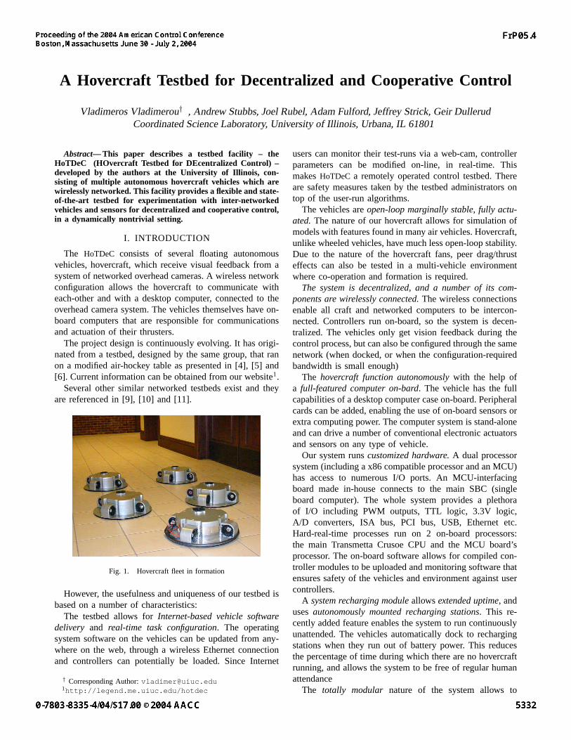
Fig. 1. Hovercraft fleet in formation
However, the usefulness and uniqueness of our testbed isbased on a number of characteristics:
The testbed allows for Internet-based vehicle softwaredelivery and real-time task configuration. The operatingsystem software on the vehicles can be updated from any-where on the web, through a wireless Ethernet connectionand controllers can potentially be loaded. Since Internet
† Corresponding Author: [email protected]://legend.me.uiuc.edu/hotdec
users can monitor their test-runs via a web-cam, controllerparameters can be modified on-line, in real-time. Thismakes HoTDeC a remotely operated control testbed. Thereare safety measures taken by the testbed administrators ontop of the user-run algorithms.
The vehicles are open-loop marginally stable, fully actu-ated. The nature of our hovercraft allows for simulation ofmodels with features found in many air vehicles. Hovercraft,unlike wheeled vehicles, have much less open-loop stability.Due to the nature of the hovercraft fans, peer drag/thrusteffects can also be tested in a multi-vehicle environmentwhere co-operation and formation is required.
The system is decentralized, and a number of its com-ponents are wirelessly connected. The wireless connectionsenable all craft and networked computers to be intercon-nected. Controllers run on-board, so the system is decen-tralized. The vehicles only get vision feedback during thecontrol process, but can also be configured through the samenetwork (when docked, or when the configuration-requiredbandwidth is small enough)
The hovercraft function autonomously with the help ofa full-featured computer on-bard. The vehicle has the fullcapabilities of a desktop computer case on-board. Peripheralcards can be added, enabling the use of on-board sensors orextra computing power. The computer system is stand-aloneand can drive a number of conventional electronic actuatorsand sensors on any type of vehicle.
Our system runs customized hardware. A dual processorsystem (including a x86 compatible processor and an MCU)has access to numerous I/O ports. An MCU-interfacingboard made in-house connects to the main SBC (singleboard computer). The whole system provides a plethoraof I/O including PWM outputs, TTL logic, 3.3V logic,A/D converters, ISA bus, PCI bus, USB, Ethernet etc.Hard-real-time processes run on 2 on-board processors:the main Transmetta Crusoe CPU and the MCU board’sprocessor. The on-board software allows for compiled con-troller modules to be uploaded and monitoring software thatensures safety of the vehicles and environment against usercontrollers.
A system recharging module allows extended uptime, anduses autonomously mounted recharging stations. This re-cently added feature enables the system to run continuouslyunattended. The vehicles automatically dock to rechargingstations when they run out of battery power. This reducesthe percentage of time during which there are no hovercraftrunning, and allows the system to be free of regular humanattendance
The totally modular nature of the system allows to
expand any aspect of it, interchange modules with othersystems. A different vehicle chassis/mechatronics configu-ration allows the system to run outdoors on a reasonablysmooth floor. Even more, the electronics can be attachedto most types of vehicles with mechatronic systems andfunction adequately with some software modifications.
II. NETWORKING AND COMMUNICATIONS
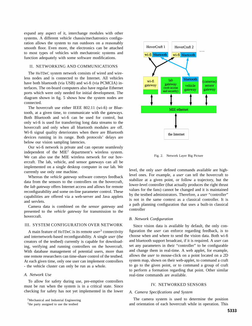
The HoTDeC system network consists of wired and wire-less nodes and is connected to the Internet. All vehicleshave both bluetooth (via USB) and wi-fi (via PCMCIA) in-terfaces. The on-board computers also have regular Ethernetports which were only needed for initial development. Thediagram shown in fig. 5 shows how the system nodes areconnected.
The hovercraft use either IEEE 802.11 (wi-fi) or Blue-tooth, at a given time, to communicate with the gateways.Both Bluetooth and wi-fi can be used for control, butonly wi-fi is used for transferring long data streams to thehovercraft and only when all bluetooth modules are off.Wi-fi signal quality deteriorates when there are Bluetoothdevices running in its range. Both protocols’ delays arebelow our vision sampling latencies.
Our wi-fi network is private and can operate seamlesslyindependent of the MIE2 department’s wireless system.We can also use the MIE wireless network for our hov-ercraft. The lab, vehicle, and sensor gateways can all beimplemented on a single desktop computer in our lab. Wecurrently use only one machine.
Whereas the vehicle gateway software conveys feedbackdata from the sensors to the controllers on the hovercraft,the lab gateway offers Internet access and allows for remotereconfigurability and some on-line parameter control. Thesecapabilities are offered via a web-server and Java appletsand servlets.
Camera data is combined on the sensor gateway andpresented to the vehicle gateway for transmission to thehovercraft.
III. SYSTEM CONFIGURATION OVER NETWORK
A main feature of HoTDeC is its remote user3 connectivityand internetwork-based reconfigurability. A single user (thecreators of the testbed) currently is capable for download-ing, verifying and running controllers on the hovercraft.With database management of potential users, more thanone remote researchers can time-share control of the testbed.At each given time, only one user can implement controllers- the vehicle cluster can only be run as a whole.
A. Network Use
To allow for safety during use, pre-emptive controllersmust be run when the system is in a critical state. Sincechecking for safety has not yet implemented in the lower
2Mechanical and Industrial Engineering3the party assigned to use the testbed
Fig. 2. Network Layer Big Picture
level, the only user defined commands available are high-level ones. For example, a user can tell the hovercraft tostabilize at a given point, or follow a trajectory, but thelower-level controller (that actually produces the right thrustvalues for the fans) cannot be changed and it is maintainedby the testbed administrators. Therefore, a user “controller”is not in the same context as a classical controller. It isa path planning configuration that uses a built-in classicalcontroller
B. Network Configuration
Since vision data is available by default, the only con-figuration the user can enforce regarding feedback, is tochoose when and where to send the vision data. Both wi-fiand bluetooth support broadcast, if it is required. A user canset any parameters in their “controller” to be configurableand change them in real-time. A web applet, for example,allows the user to mouse-click on a point located on a 2Dsystem map, shown on their web-applet, to command a craftto go to the given point, or to command a group of craftto perform a formation regarding that point. Other similarreal-time commands are available.
IV. NETWORKED SENSORS
A. Camera Specifications and System
The camera system is used to determine the positionand orientation of each hovercraft while in operation. This
information is then broadcast wirelessly to the hovercraft toallow each craft to calculate the appropriate control actions.
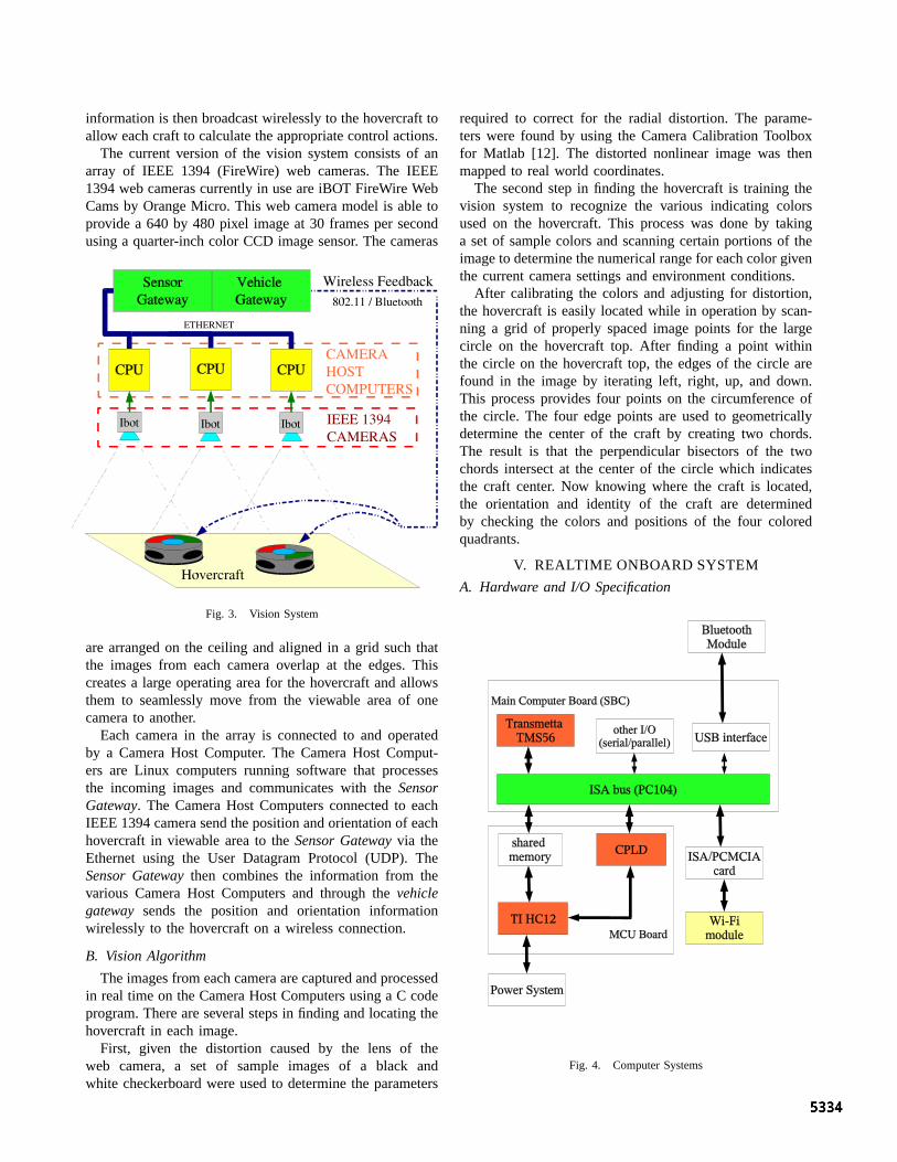
The current version of the vision system consists of anarray of IEEE 1394 (FireWire) web cameras. The IEEE1394 web cameras currently in use are iBOT FireWire WebCams by Orange Micro. This web camera model is able toprovide a 640 by 480 pixel image at 30 frames per secondusing a quarter-inch color CCD image sensor. The cameras
Fig. 3. Vision System
are arranged on the ceiling and aligned in a grid such thatthe images from each camera overlap at the edges. Thiscreates a large operating area for the hovercraft and allowsthem to seamlessly move from the viewable area of onecamera to another.
Each camera in the array is connected to and operatedby a Camera Host Computer. The Camera Host Comput-ers are Linux computers running software that processesthe incoming images and communicates with the SensorGateway. The Camera Host Computers connected to eachIEEE 1394 camera send the position and orientation of eachhovercraft in viewable area to the Sensor Gateway via theEthernet using the User Datagram Protocol (UDP). TheSensor Gateway then combines the information from thevarious Camera Host Computers and through the vehiclegateway sends the position and orientation informationwirelessly to the hovercraft on a wireless connection.
B. Vision Algorithm
The images from each camera are captured and processedin real time on the Camera Host Computers using a C codeprogram. There are several steps in finding and locating thehovercraft in each image.
First, given the distortion caused by the lens of theweb camera, a set of sample images of a black andwhite checkerboard were used to determine the parameters
required to correct for the radial distortion. The parame-ters were found by using the Camera Calibration Toolboxfor Matlab [12]. The distorted nonlinear image was thenmapped to real world coordinates.
The second step in finding the hovercraft is training thevision system to recognize the various indicating colorsused on the hovercraft. This process was done by takinga set of sample colors and scanning certain portions of theimage to determine the numerical range for each color giventhe current camera settings and environment conditions.
After calibrating the colors and adjusting for distortion,the hovercraft is easily located while in operation by scan-ning a grid of properly spaced image points for the largecircle on the hovercraft top. After finding a point withinthe circle on the hovercraft top, the edges of the circle arefound in the image by iterating left, right, up, and down.This process provides four points on the circumference ofthe circle. The four edge points are used to geometricallydetermine the center of the craft by creating two chords.The result is that the perpendicular bisectors of the twochords intersect at the center of the circle which indicatesthe craft center. Now knowing where the craft is located,the orientation and identity of the craft are determinedby checking the colors and positions of the four coloredquadrants.
V. REALTIME ONBOARD SYSTEM
A. Hardware and I/O Specification
Fig. 4. Computer Systems
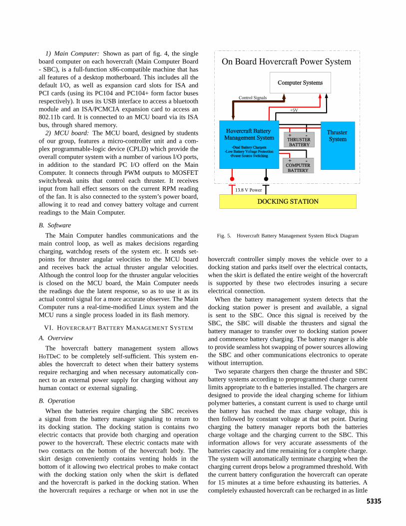
1) Main Computer: Shown as part of fig. 4, the singleboard computer on each hovercraft (Main Computer Board- SBC), is a full-function x86-compatible machine that hasall features of a desktop motherboard. This includes all thedefault I/O, as well as expansion card slots for ISA andPCI cards (using its PC104 and PC104+ form factor busesrespectively). It uses its USB interface to access a bluetoothmodule and an ISA/PCMCIA expansion card to access an802.11b card. It is connected to an MCU board via its ISAbus, through shared memory.
2) MCU board: The MCU board, designed by studentsof our group, features a micro-controller unit and a com-plex programmable-logic device (CPLD) which provide theoverall computer system with a number of various I/O ports,in addition to the standard PC I/O offerd on the MainComputer. It connects through PWM outputs to MOSFETswitch/break units that control each thruster. It receivesinput from hall effect sensors on the current RPM readingof the fan. It is also connected to the system’s power board,allowing it to read and convey battery voltage and currentreadings to the Main Computer.
B. Software
The Main Computer handles communications and themain control loop, as well as makes decisions regardingcharging, watchdog resets of the system etc. It sends set-points for thruster angular velocities to the MCU boardand receives back the actual thruster angular velocities.Although the control loop for the thruster angular velocitiesis closed on the MCU board, the Main Computer needsthe readings due the latent response, so as to use it as itsactual control signal for a more accurate observer. The MainComputer runs a real-time-modified Linux system and theMCU runs a single process loaded in its flash memory.
VI. HOVERCRAFT BATTERY MANAGEMENT SYSTEM
A. Overview
The hovercraft battery management system allowsHoTDeC to be completely self-sufficient. This system en-ables the hovercraft to detect when their battery systemsrequire recharging and when necessary automatically con-nect to an external power supply for charging without anyhuman contact or external signaling.
B. Operation
When the batteries require charging the SBC receivesa signal from the battery manager signaling to return toits docking station. The docking station is contains twoelectric contacts that provide both charging and operationpower to the hovercraft. These electric contacts mate withtwo contacts on the bottom of the hovercraft body. Theskirt design conveniently contains venting holds in thebottom of it allowing two electrical probes to make contactwith the docking station only when the skirt is deflatedand the hovercraft is parked in the docking station. Whenthe hovercraft requires a recharge or when not in use the
Fig. 5. Hovercraft Battery Management System Block Diagram
hovercraft controller simply moves the vehicle over to adocking station and parks itself over the electrical contacts,when the skirt is deflated the entire weight of the hovercraftis supported by these two electrodes insuring a secureelectrical connection.
When the battery management system detects that thedocking station power is present and available, a signalis sent to the SBC. Once this signal is received by theSBC, the SBC will disable the thrusters and signal thebattery manager to transfer over to docking station powerand commence battery charging. The battery manger is ableto provide seamless hot swapping of power sources allowingthe SBC and other communications electronics to operatewithout interruption.
Two separate chargers then charge the thruster and SBCbattery systems according to preprogrammed charge currentlimits appropriate to th e batteries installed. The chargers aredesigned to provide the ideal charging scheme for lithiumpolymer batteries, a constant current is used to charge untilthe battery has reached the max charge voltage, this isthen followed by constant voltage at that set point. Duringcharging the battery manager reports both the batteriescharge voltage and the charging current to the SBC. Thisinformation allows for very accurate assessments of thebatteries capacity and time remaining for a complete charge.The system will automatically terminate charging when thecharging current drops below a programmed threshold. Withthe current battery configuration the hovercraft can operatefor 15 minutes at a time before exhausting its batteries. Acompletely exhausted hovercraft can be recharged in as little
as 150 minutes. When the unit is docked and the SBC hasauthorized the use of docking power, there is no draw on thebatteries all power is provided by the docking station. As anadditional safety if external power is ever lost, the hovercraftwill automatically default to battery power regardless of theSBC settings.
There is no need to wait for the hovercraft to com-pletely recharge for before running additional experiments.Anytime during the charging period a user can overridethe automatic charging sequence and run a control on ahovercraft with whatever power is available in its batterysystem. The battery manger continuously reports the voltageand charge current to the SBC, which then in turn transmitsit to the web server. Using calculations of the vehicle’scurrent consumption during a particular experiment andcurrent consumption rate combined with the voltage onthe batteries, a very accurate calculation of the powerremaining for a particular hovercraft mission is possible.The software automatically verifies that the projected powerin a hovercraft’s battery packs is sufficient to complete theentire duration of the controller experiment that the user hasentered.
VII. MECHANICAL VEHICLE SPECIFICATIONAND FUNCTIONALITY
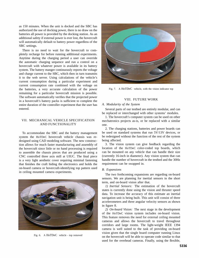
To accommodate the SBC and the battery managementsystem the HoTDeC hovercraft vehicle chassis was re-designed using CAD modeling software. The new construc-tion allows for much faster manufacturing and assembly ofthe hovercraft since little or no hand processing is requiredto assemble the chassis pieces that are produced using aCNC controlled three axis mill at UIUC. The final pieceis a very light aesthetic cover requiring minimal fasteningthat finishes the craft hiding the electronics and holds theon-board camera or hovercraft-identifying top pattern usedin ceiling mounted camera experiments.
Fig. 6. A HoTDeC vehicle - top removed
Fig. 7. A HoTDeC vehicle, with the vision indicator top
VIII. FUTURE WORK
A. Modularity of the System
Several parts of our testbed are entirely modular, and canbe replaced or interchanged with other systems’ modules.
1. The hovercraft’s computer system can be used on othermechatronics projects as-is, or be replaced with a similarone.
2. The charging stations, batteries and power boards canbe used on standard systems that run 5V/13V devices, orbe redesigned without the function of the rest of the systembeing affected.
3. The vision system can give feedback regarding thelocation of the HoTDeC color-coded top boards, whichcan be mounted on any vehicle that can handle their size(currently 16-inch in diameter). Any vision system that canhandle the number of hovercraft in the testbed and the 30Hzrequirement can be swapped in.
B. Expansions
The two forthcoming expansions are regarding on-boardsensors. We are planning for inertial sensors in the shortterm, and on-board vision after that.
1) Inertial Sensors: The estimation of the hovercraftstates is currently done using the vision and thruster speeddata. To increase the accuracy of this estimate an inertialnavigation unit is being built. This unit will consist of threeaccelerometers and three angular velocity sensors as shownin figure 8.
2) On-board Vision: The next stage in the developmentof the HoTDeC vision system includes on-board vision.This feature removes the need for external ceiling mountedcameras and allows the hovercraft to travel throughoutcorridors and large rooms. The light-weight IEEE 1394camera is well suited to the task of providing on-boardvision given that the single board computer running Linuxon the hovercraft will be able to operate code similar to thatused for the overhead cameras. Finally, using the flexible,

on-board IEEE 1394 camera system in conjunction with ahyperbolic mirror, 360 degree vision can be implementedto allow the hovercraft to see and move autonomously inall directions.
Fig. 8. Estimation with Inertial Sensors
The estimator uses a method of removing the correlationresulting from the integration of the accelerometer signalsfrom Gelb [1]. This method is combined with Julier’sgeneralization of the Kalman filter [2] and used to estimatethe states of the non-linear system without linearizing thesystem.
Current work consists of the combination of this conceptwith the concept of the multi-rate problem in Lall [3].
REFERENCES
[1] Arthur Gelb, Applied optimal estimation, The Analytic SciencesCorporation, 1986.
[2] Simon Julier, Jeffrey Uhlmann, and Hugh F. Durrant-Whyte, A newmethod for the nonlinear transformation of means and covariance infilters and estimators, IEEE Transactions on Automatic Control 45(2000), no. 3.
[3] Sanjay Lall, and Geir Dullerud, An LMI solution to the robustsynthesis problem for multi-rate sampled-data systems, Automatica37 (2001).
[4] Stubbs and Dullerud: Networked control of Distributed Systems: aTestbed ASME 2001 International Mechanical Engineering Congressand Exposition
[5] Stubbs, Vladimerou, Vaughn and Dullerud: Design of a VehicleNetwork Control Testbed ACC 2002
[6] Stubbs, Vladimerou, Rubel and Dullerud: Distributed Control ofNetwork Vehicles CDC 2002
[7] Bluetooth Specification Version 1.1, Bluetooth SIG, 2001.[8] IEE 802.11 specification, the IEE 802.11 WIG[9] Caltech’s MVWT, MVWT-II
http://www.cds.caltech.edu/˜mvwt/[10] Formation Flying at MIT
http://www.mit.edu/people/jhow/ff.html[11] Roboflag
http://roboflag.mae.cornell.edu/[12] Camera Calibration Toolbox for Matlab, Jean-Yves Bouguet, MRL
- Intel Corp.http://www.vision.caltech.edu/bouguetj/calib doc/