a hybrid/analog-digital one-parameter optimizer
TRANSCRIPT
32 Annales de l'Association internationale pour le Calcul analogique N" 1 - - ]anvier 1964
A HYBRID/ANALOG.DIGITAL ONE-PARAMETER OPTIMIZER ~:"
b~ B a k e r A. M I T C H E L L ~
SUMMARY
In th,s paper the author examines whether it ,s possible to determine, with the aid of an analogue computer, simulating a system the best method to locate automatically the optimum value, provided such a value exists, of a parameter mfluenc,ng in an undetermined way the behaviour of this system
Afterwards, the author examines if the solutmn so obtained is un,que.
Introduction.
G~ven a system containing a parameter whose in- fluence on the system's behavior is undetermined, devise a means of automatically selecting the optimum value of this parameter with respect to some performance criterion of the system, if this optimum value exists.
The thought of a system which optimizes one of its own parameters is quite intellectually pleasing; and since A.A. Feldbaum's first paper on the subject ap- peared in September, 1958 [1], the computer and con- trois literature has been replete with schemes which reputedly accomplished this feat. However, many of the proposed methods were never tried, and the com- plexity of others has rendered their implementation unfeasible.
Suppose that the performance criterion for a posi- tioning serve is to minimize the mean square error of the response; and that within the system there is a parameter having one value, unknown to the designer, which will cause the system to best meet this criterion.
With an analog computer simulation o.f the system, does one best method exist for automatically locating the optimum value of the parameter ? Is the optimum optimizer unique ?
The Search.
It is evident that any method for locating the opti- mum value must first begin blindly because Nature is random and can place this value anywhere within the parameter's range of variation with equal probability. Since this is the case, the one best point to look first is in the exact center of the parameter's range. While not actually expecting to find the optimum value at this point, we can always be assured of being able to eliminate at least half the range after determining the direction which causes the system's performance to improve. This is done by taking a trial test at a point either slightly above or slightly below the half way point and comparing it with the system's performance at the half way point. Again the question arises as to where within the remaining one-half range is the best
* Manuscript received May 6, 1963. ** The University of Arizona, Department of Electrical
Engineeiing.
location for placing the second search point, And again this will be the mid-point of the remaining range.
By anticipating Nature's random strategy, the opti- mtu-n counterstrategy is seen to be that of successively eliminating one-half of the unsearched range Lmtil the desired resolution is reached.
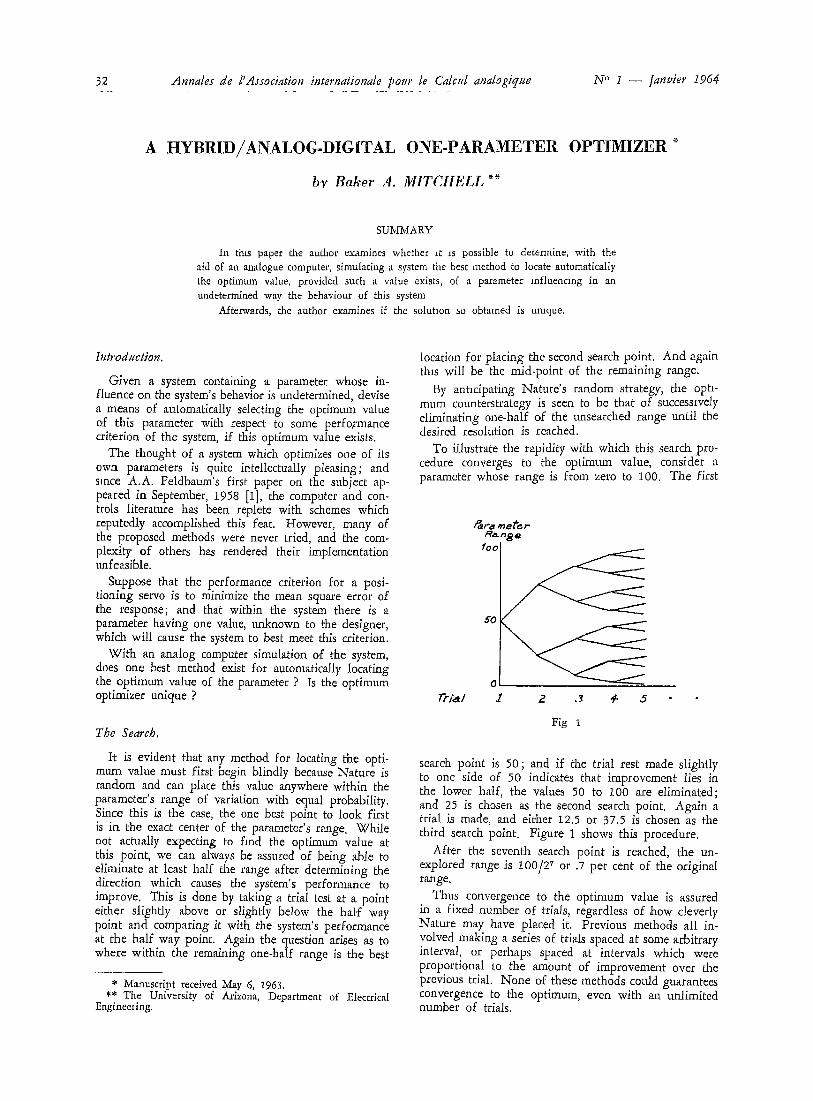
To illustrate the rapidity with which this search pro- cedure converges to the optimum vaiue, consider a parameter whose range is from zero to 100. The first
R ~ e /oo
50
Trial J 2 J ÷ 5
Fig I
search point is 50; and if the trial rest made slightly to one side of 50 indicates that improvement lies in the lower ha'if, the values 50 to 100 are eliminated; and 25 is chosen as the second search point. Again a trial is made, and either 12.5 or 37.5 is chosen as the third search point. Figure 1 shows this procedure.
After the seventh search point is reached, the un- explored range is 100/27 or .7 per cent of the original range.
Thus convergence to the optimum value is assured in a fixed number of trials, regardless of how cleverly Nature may have placed it. Previous methods all in- volved making a series of trials spaced at some arbitrary interval, or perhaps spaced at intervals which were proportional to the amotmt of improvement over the previous trial. None of these methods cotdd guarantees convergence to the optimum, even with an unlimited number of trials.
B.A. Mitchell : A hybrid/analog-digital one-parameter optimize;
Q~ 33
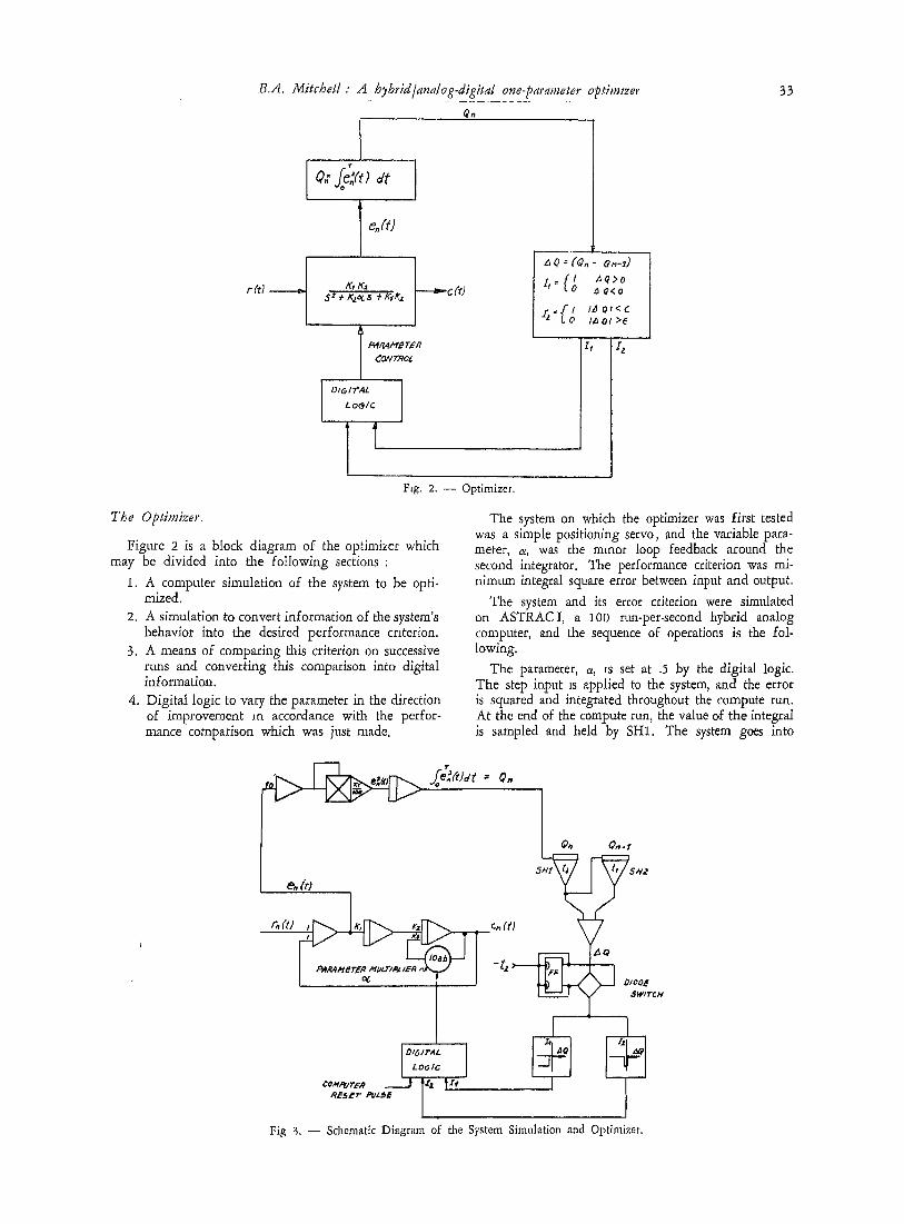
The Optimizer.
r(d t
Q: (~ ) s t
I Iq4RA,aqETFR CONTROL
D~GIT"AL t.oOIE
I
I I - f l aq>o
f " l O a @<o
r = ~ ' l IAO/<C =z LO I~ O/ >e
z, I e
F~g. 2. - - Optimizer.
Figure 2 is a block diagram of the optimizer which may be divided into the following sections :
1, A computer simulation of the system to be opti- mized,
2. A simulation to convert information of the system's behavior into the desired performance criterion.
3. A means of comparing this criterion on successive runs and converting this comparison into digital information.
4. Digital logic to vary the parameter in the direction of improvement m accordance with the perfor- mance comparison which was just made.
The system on which the optimizer was first tested was a simple positioning servo, and the variable para- meter, ~, was the minor loop feedback around the second integrator. The performance criterion was mi- nimum integral square error between input and output.
The system and its error criterion were simulated on ASTRACI, a 100 run-per-second hybrid analog computer, and the sequence of operations is the fol- lowing.
The parameter, oe, Is set at .5 by the digital logic. The step input is applied to .the system, and the error is squared and integrated throughout the compute run. At the end of the compute run, the value of the integral is sampled and held by SH1. The system goes into
&(t)
¢OM,~yBR
T= ~oe.(tJat = ~.
~ c~ CH
I OISITAL ] LOGIC =
it, fx ,
!o O/oo£
SWITCH
Fig ~,. - - Schematic Diagram of the System Simulation and Optimizer.

34 Annales de l'Association internationale pout' le Calcul analogique N ~' 1 - - ]anwer 1964
CO~PUT"~9
F F,~
6!
6Z
6J,, ,
G ÷
68
A--k_l--t_3-q F-I U-1 ,.V3 V-q_.
I I
F---1
I I
I l
B
1 I
Fxg 4 - - Pulse Sequence for D,gltal Log,c.
reset, and c~ is changed to .5 + e by the digital logic. The step input is again applied, and the integral square error is computed However, SH2 samples and holds the o'ld value of SH1, jttst before SH1 releases to sampIe the value of the new integral. The system now goes into reset; and SH2, holding Q (.5t, is subtracted from SH1, holding Q (.5 + e), thus yielding A Q, which is put into a comparator and << window >> cir- cuit to provide information to the digital logic. This information then causes ~ to be set for the next compute run either to .75 or .25, depending upon the sign of /x Q. With t~ now set, the step input is applied to the system; and the entire routine is repeated
n ] g Q becomes less than some preset value, in- dicati that the optimum value has been reached to within this preset limit.
Figure 3 shows the schematic of the test set up,
A Hybrid-Coeffident Setting Unit.
Combining digital logic and memory with a wide- band digital-analog multiplier results in giving the optimizer ample reserve in speed and resolution for future applications.
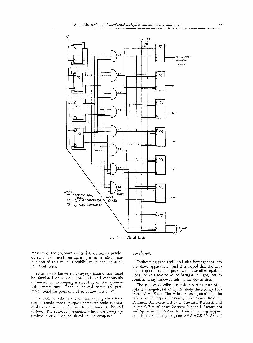
Figure 4 is a timing chart of the pulse sequence in the digital logic. An optimization cycle is :
1. G, sets FF1 = 1; FFe to FF~ = 0. 2. FF~ holds multiplier line 7, 3. G2 sets FF1 = 0, if I, ----- 0; FF., ~- 1. 4. FF a holds multiplier line 7. 5. G,, sets FF,_, = 0, if I~ = 0, FF a = 1. 6. FF~ holds multiplier line 7. 7. G4 sets FF.~ = 0, if It = 0; FF4 = 1.
This operation continues until either I., inhibits all flip-flops, indicating that the optimum has been reached to within e, or until FF 7 is set by G; , Indicating that the optimum has been reached to within the resolution of the device (.7%),
The digital logic/memory has a speed capacity of 1 Mc, and the multiplier's speed is limited, in this case, to 200 kc by the response of the operational amplifier. Therefore, the speed of this device can ex- ceed that of any repetitive computer now available on which to simulate the system being optimized. Upon the completion of ASTRAC II, a 1 kc repetitive com- puter, the total optimization time will be .014 sec.
The Results.
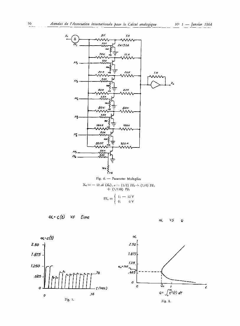
Appendix A gives the denvatmn for the system transfer function. The integral square error expression is also derived, and hgure 4 shows a plot of the integral square error as a function of the parameter Also the optimum value for ~ as a ftmcLion of K, and K2 is derived, and it is seen that c~0 = (K,/K.~) 1/2.
As indicated in figure 3, K1/K~ = .5; therefore, the optimum value of ¢~ is .51/2 or .707. The range of c~ selected for the test was from 0 to, 2.5. Inci- dently, this range was selected arbitrarily before the theoretical optimtma value was calcuiated. Figure 5 is a pi'cture of an oscilloscope trace showing the wave- form at the output of the optimizer during one series of optimizing runs. The optimum value of the para- meter lies between the values used in the thirteenth and fourteenth trials. Interpolation o.f the graph m figure 5 yields an optimum value of .76; this value deviates from the theoretical value by 2 I/2 per cent, full range. Subsequent tests with different gains on K1 and K._, yielded comparable accuracy.
Applications,
With the assured capability of finding the optimum value of a parameter after a search of only .14 sec, several applications immediately suggest themselves.
For systems subjected to random inputs and distur- bances the true optimum value could be defined by a
B.A. Mitchell .' A hybrd/analog-digital o~ae-parameter optimizer 35
H~rE~ '~'.l CoI,¢POI'#R
*a Z a #~a~
II
I
I .pumE. .... \ a'Aa'D [
~ . 7"o ,°aRa,~g~rg, q
MUI. 77.Ol.l-W.R
L/NR$
lqg, ~, - - Digital Logic.
J 1
1 .
ro * ' /~ T
measure of the optimum values derived from a number of runs For non-linear systems, a mathematical com- putation of this value is prohibitive, is not impossible m most cases.
Systems with known time-varying characteristics could be simulated on a slow time scale and continuously optimized while keeping a recording of the optim,um value versus time. Then in the real system, the para- meter could be programmed to follow this curve.
For systems with unknown time-varying characteris- tics, a simple specml purpose computer could continu- ously optimize a model which was tracking the real system. The system's parameter, which was being op- timized, would then be slaved to the computer.
Co.cluslon.
Forthcoming papers will deal with investigations into the above applications; and it is hoped that the heu- listic approach of this paper will cause other applica- tions for this scheme to be brought to light, not to mention many improvements in the device itself,
The project described in this report is part of a hybrid analog-digital computer study &rected by Pro- fessor G,A, Korn The writer is very grateful to the Office of Aerospace Research, Information Resea_rch Division, Air Force Office of Scientific Research and to the Office of Space Sciences, National Aeronautics and Space Administration for their continuing support of this study under joint grant AF-AFOSR-89-63; ,'rod
36 Annales de l'Assocmtion internationale pour le Calcul analogique N" I - - ]anvier 1964
F~
ff/q 5 ~
/A4
(> _xo
BOK r ~- Bole
. o x .d ---- ,eo*¢
PF z
;&
$ZOK X, J, ~r
Fig, 6, - - Parameter Multlpliei
Xo = -- to ,~b ( x , ) , a = (112) rF, + (114) ;~., + (l/t2s) FF,
F F n = / 1; - - 12V ( 0; OV
" c (t) vs t ime
2.50
1.8T5
.625
0
0 ,14 Fig, 7.
(see)
06
Z.50 I
1"875 I /..25
°lo='YOT ~_~ , 6 2 5
0 0
I
Fig. 8.

B,A. Mitchell" A h2bpid/analog-digilal one-parameter optimizer 37
to International Business Machines Corporation for their contributmn of the diDtal modules which made the implementation of this device possible. The writer is also grateful to Drs. T.L. Martin, Dean of Engin- eering, and P.E. Russell, Head, Electrical Engineering Department, for their encouragement and contribution of University facilities.
APPENOIX A
,q t's)
K1 K2 G (~) = - - ( - - )
S S + K . a
C (s) G (s) K~ K.a
R(s) - 1 -4- O(s) S "° q- KuczS q- K,K.a
G (s) R (4 E (~) = ~ (~) - - C (~) = R (~) - -
1 = R ( 4 ( - - )
I q- G (s)
S ~ q- K. ,¢S E (4 = ~ (4 (-s,_, + K., ~ S + K~ K:
0)
) (2)
Let R(~) = 1/s.
E 0) = S + K 2 ~
S'-' + K2 o~S + K 1Ka
1 L~ ~ IS.E. = e'-'(t) - - 27rj ~
K1 K,2 + K., e a 2 I.SE =
2 K, K.? a
For minimum I S.E,
E(s) E(-s) ds
K, + Ka e?
2 K 1 K2 a
and
I.S.E. Kt - - K.. ~
¢~ 2 K I K._, a oe'-'
~o m_ ~ / " K1 ¥ K,,
(3)
Note : Equation 3 is plotted in figure 4
- o (4)
(5)
REFERENCE8
I t ] FELDBAUM, A A and R A. VELERSHTEIN: Develop- ment of an Almost Optimal System by Means of an Elec- tronic Analog ; Automation and Remote Conlrol ; English translation p. 808, June 1959.
[2] WAIT, J.V. and B A MITCHELL : A Simple Solid-State Digital-to-Analog Converter for Hybrid Computing Sys- tems, ACL Memo No. 61, Electrical Eng,neering Dept., University of Arizona, Tucson, Arizona, 1963.