a low resolution image sensor for tactile vision sensory ... 3/issue...
TRANSCRIPT

ISSN: 2277-3754
ISO 9001:2008 Certified International Journal of Engineering and Innovative Technology (IJEIT)
Volume 3, Issue 11, May 2014
Page 1 of 7
Abstract- Tactile displays used for visual sensory substitution are mostly have low-resolution due to spatial resolution in human body, while most of the image sensors adopted for this purpose, are high-resolution cameras. This paper presents the approach of using low resolution image sensors instead of digital cameras, for tactile vision sensory substitution. Two methods were implemented; one based on Matlab, and the other was a hardware implementation. Matlab was used to simulate the low resolution image sensor using a web camera, and convert the captured image to a tactile pattern image. The same captured image is subjected to conventional image processing techniques to get another tactile pattern. Both patterns for many scene images were compared. A case study using optical mouse image sensor was also implemented using two configurations; the first was a PC based, and the second was a microcontroller based. Test results confirm the possibility of this approach. Keywords: sensory substitution, tactile vision, optical mouse sensor.
I. INTRODUCTION According to WHO (World Health Organization) reports, 39 million people are estimated to be blind worldwide, about 90% of them live in developing countries [1].Most of them are very poor to afford the cost of the blind assistance devices. Researchers are continuing to find means of reducing devices costs. One of these devices is the Sensory substitution device (SSD).
Persons who become blind do not lose the capacity to see. Usually, they lose the peripheral sensory system (the retina), but retain central visual mechanisms [2]. In the intact visual system, the optical image goes only to the retina, where it is turned into electrical impulses in the optic nerve; the perceived image is re-created in the brain [2]. Thus, it can be thought of the retina as a very efficient vision sensor. SSDs encode visual information to auditory or tactile representation, to enable the blind to ‘see’ in a noninvasive manner with their intact senses. They substitute the lost vision sensor with an artificial vision sensor, but does not connected to the optical nerve, instead it sends visual data to the brain via other sensory modality. Paul Bach-y-Rita [2] stated that also a poor resolution sensory substitution system can provide the information necessary for the perception of complex images. The blind person brain has the ability to process tactile vision data through the vision cortex, and can be learned to
process the low resolution scene-data coming from the skin (rather than the eye) and extracts some wanted features. A sensory substitution system can be thought of as composed of a number of components of the kind illustrated in Fig. 1.
Fig. 1: Structure of a sensory substitution system.
Information of the scene is typically acquired by the sensing unit, using one or more sensor types. The sensors outputs are processed by the processing and control unit and coupled to the display unit. The actuated display presents the information to one of the human sensory modality, which is eventually transduced and processed by the intrinsic sensory system of the body.
A. Related Works An early example of tactile sensory substitution is provided by the Tactile Vision Sensory Substitution (TVSS) system, created by Paul Bach-y-Rita and his collaborators [3]. They gave the blind person the ability to manipulates a television camera mounted on a tripod, which scans objects placed on a table in front of him. The subject can aim a TV-camera, equipped with a zoom lens, at different parts of the room. Four hundred solenoid stimulators are arranged in a 20×20 array built into a dental chair. The stimulators are ‘Teflon’ tips which vibrate against the skin of the back. Paul Bach-y-Rita overviewed most of his researches in this field. The sensing units were mainly general purpose cameras. They used array of stimulators in contact with the skin of one of several parts of the body, including the abdomen, back, thigh ,forehead, and fingertip [4]. Markus Loose etal. [5] implemented a camera system having 400 pixels (20×20) of adaptive photoreceptors to be used for tactile vision. Kajimoto etal. designed and produced the forehead retina system, which is composed of
A low resolution image sensor for tactile vision sensory substitution
Mazin H. Aziz1, Saad D. Sulaiman2 and Luqman S. Ali3 [email protected], [email protected], [email protected]
1Department Computer Engineering, College of Engineering, Mosul University, Mosul, Iraq. 2Department Electronics, College of Electronics Engineering, Mosul University, Mosul, Iraq. 3Department Electrical Engineering, College of Engineering, Mosul University, Mosul, Iraq.
ISSN: 2277-3754
ISO 9001:2008 Certified International Journal of Engineering and Innovative Technology (IJEIT)
Volume 3, Issue 11, May 2014
Page 2 of 7
a camera, DSP processing element and an electro-tactile display that can be mounted on the blind person forehead [6]. On the other hand researches have been done using visual to auditory instead of tactile [7]. Researchers often, used TV, CCD, Mobile-Phone, WEB or CMOS cameras for vision sensing. While IR transducers, ultrasound transducers, Laser, GPS, or Internet resources are used for obstacle detection and navigational aid for the blinds. None of the researches have used the PC-optical mouse image sensor for sensory substitution, nevertheless some of them used the imaging capability of the mouse sensor. WANG Xin etal. used it for surface shape analyzing [8]. It was also used to build an incremental rotary encoder, and an absolute rotary encoder by M. Tresanchez etal. [9] [10]. Boning Zhang etal. used it to construct a system for motion detection in normal vision environment [11]. It is also presented as a counterfeit coin detector applied to the two-Euro case [12]. The mouse sensor is proposed to measure yarn diameter [13]. It seems a suitable device to be tested as a low resolution image sensor in this research.
II. METHODS AND MATERIALS A. First method
Matlab was used to simulate a low resolution image sensor by using web camera of a 640×480 pixels. the scene image captured by the camera was converted to gray image, scaled down to the tactile resolution using distinct block procedure by taking the mean value as in Fig. 2.
Fig. 2: Down scaling from the webcam resolution to simulate the low resolution image sensor using distinct block procedure depending on the mean value.
At this state the scaled down image is a gray level image equivalent to an image taken by a low resolution image sensor. This scaled down image is converted to a binary image by using threshold only to suite tactile pattern. Two tactile pattern resolutions were adopted and demonstrated (18×18) and (32×32) pixels as illustrated in Fig. 3, which we called the first image pipeline.
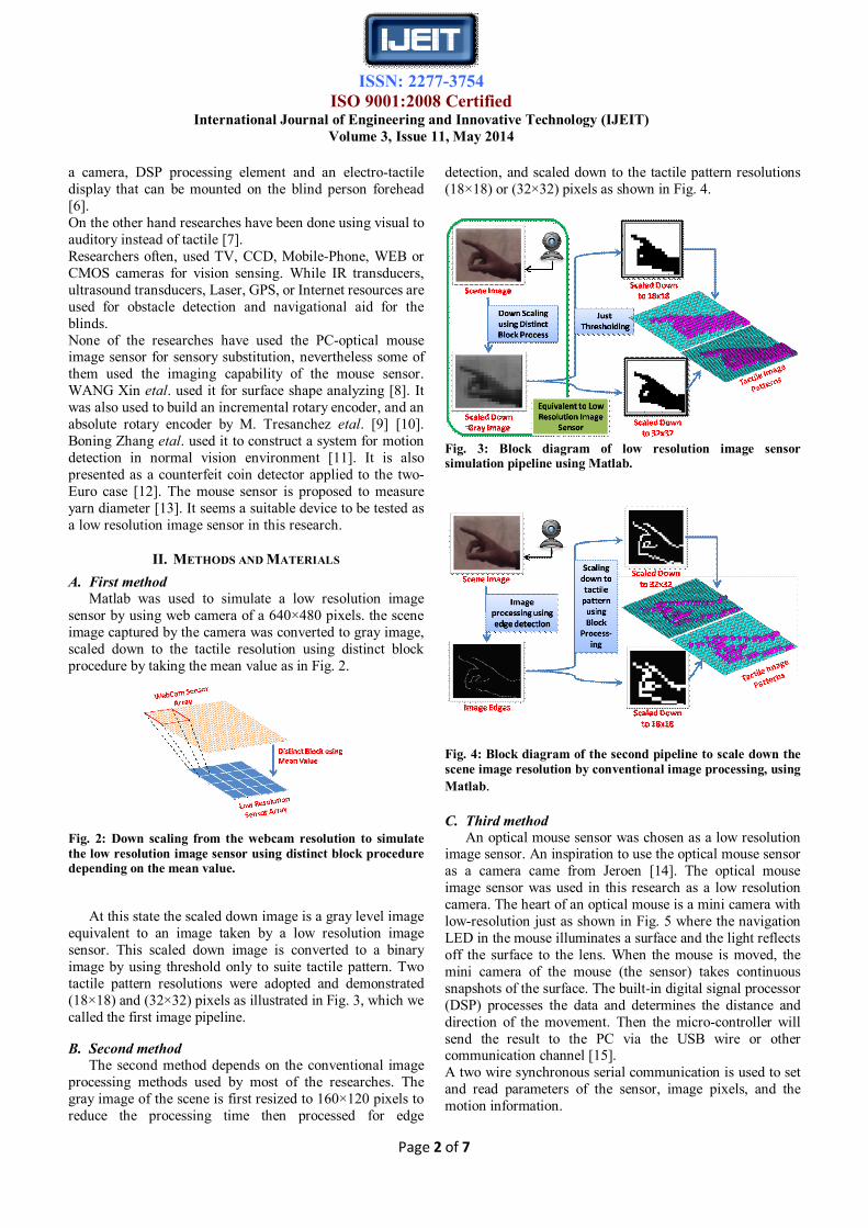
B. Second method The second method depends on the conventional image
processing methods used by most of the researches. The gray image of the scene is first resized to 160×120 pixels to reduce the processing time then processed for edge
detection, and scaled down to the tactile pattern resolutions (18×18) or (32×32) pixels as shown in Fig. 4.
Fig. 3: Block diagram of low resolution image sensor simulation pipeline using Matlab.
Fig. 4: Block diagram of the second pipeline to scale down the scene image resolution by conventional image processing, using Matlab.
C. Third method An optical mouse sensor was chosen as a low resolution
image sensor. An inspiration to use the optical mouse sensor as a camera came from Jeroen [14]. The optical mouse image sensor was used in this research as a low resolution camera. The heart of an optical mouse is a mini camera with low-resolution just as shown in Fig. 5 where the navigation LED in the mouse illuminates a surface and the light reflects off the surface to the lens. When the mouse is moved, the mini camera of the mouse (the sensor) takes continuous snapshots of the surface. The built-in digital signal processor (DSP) processes the data and determines the distance and direction of the movement. Then the micro-controller will send the result to the PC via the USB wire or other communication channel [15]. A two wire synchronous serial communication is used to set and read parameters of the sensor, image pixels, and the motion information.

ISSN: 2277-3754
ISO 9001:2008 Certified International Journal of Engineering and Innovative Technology (IJEIT)
Volume 3, Issue 11, May 2014
Page 3 of 7
The ADNS-2610 mouse sensor was used in this work with two configurations; PC-based, and microcontroller-based:
Fig. 5: Optical mice illuminate an area of the work surface with an LED, and the patterns seen are reflected onto the navigation sensor [15].
C.1 PC-based
For the PC-based; the mouse image sensor was interfaced directly to PC via parallel port. The control orders and data were transferred serially through the two communication lines of the sensor, SCLK for synchronization and SDIO for bidirectional data as shown in Fig. 6.
Fig. 6: PC-based configuration (the first pipeline).
Visual Basic program was written to read the scene image data from the image sensor. The image is a 64-gray level 18×18 pixels. For each frame the pixel-sum was read from the mouse sensor-DSP processor register (0×07) and used to calculate the pixel threshold level according to equation(1): 풑풊풙풆풍_풕풉풓.= 푷풊풙풆풍_푺풖풎 + 휟
= ퟐ. ퟓ(풂풗풆풓풂품풆풑풊풙풆풍) + 휟(ퟏ)
This threshold was used to convert the captured image to binary in real time using equation (2):
푩풊풏풂풓풚푷풊풙풆풍 = ퟎ풑풊풙풆풍 < 푝푖푥푒푙_풕풉풓.ퟏ풑풊풙풆풍 > 푝푖푥푒푙_풕풉풓.
� (ퟐ)
Deferent values of Δ were tested to get the most suitable value for pixel_ threshold. The resultant binary image is equivalent to the tactile pattern image with no need for down scaling.
C.2 Microcontroller-based For the microcontroller-based; the mouse sensor was
interfaced to an8951 microcontroller, using the(µp2) training kit as illustrated in Fig. 7. The two synchronous communication lines of the sensor were connected to port1 of 8951. The 64-gray image captured by the mouse sensor was converted to binary image using equations (1) and (2). The binary image was displayed frame by frame on a 16×16 LED-matrix array. Two rows and two columns were discarded from the 18×18 captured scene image to match the LED-matrix array size.
Fig. 7: Microcontroller-based configuration (the second pipeline).
For each of the two configurations, the following procedures were implemented. C.2.1. The original optical part (lens and illumination led) of the mouse was kept as it is to test the hardware validity, and the vision capabilities of the optical sensor. A standard USAF test chart were printed on a white A4 paper size using a standard low cost inkjet printer .Images were taken by scanning the USAF chart by the mouse. The optical mouse sensor acquires sequential surface images (size: 1.82mm2) up to 4 image frames per second (fps) which is the maximum frame rate for the ADNS-2610 mouse sensor. C.2.2. The original optical part of the mouse sensor(lens and illumination LED) were removed, and a new lens was attached, so it can be used as a camera as shown in Fig. 8. The new optics was an off the shelf web camera lens of 6mm lens focus, and 62 visual angle. It was adapted directly to the mouse sensor. The altered image sensor was used to capture scene images and map them to tactile images

ISSN: 2277-3754
ISO 9001:2008 Certified International Journal of Engineering and Innovative Technology (IJEIT)
Volume 3, Issue 11, May 2014
Page 4 of 7
on the PC screen and LED matrix, for the first and second hardware configurations respectively.
Fig. 8: Webcam lens attached to the optical mouse image sensor.
III.RESULTS A. Results of Matlab simulation are illustrated in FIG. 9 for the low resolution pipeline, and FIG. 10 for the conventional image processing pipeline.
B. For the same scene image, two tactile pattern resolutions were demonstrated, (18×18) and (32×32) pixels. Images from different scenes were captured and passed via the two simulation pipelines, and each couples of outputs (one from each line) were subjected to comparison. C. PC-based configuration results were an (18×18) tactile pattern image displayed on the PC screen. Images were captured 4 frames per second (fps), converted to binary by thresholding and displayed in real time. Some of the results are shown in Fig. 11. D. The microcontroller-based configuration resultant tactile pattern images were displayed on a 16×16 LED-matrix. Three samples of the tactile pattern images are shown in Fig. 12.
Fig. 10: (a)Some of the captured images by the web camera. Tactile image patterns for 18×18 in (b), and 32×32 in (c) after edge detection, thresholding, and down scaling.
Fig. 11: Images captured by the optical mouse sensor after web camera lens adaptation. (a)Captured gray-level images, (b) tactile pattern with rectangular pixel shape, and (c) tactile pattern with round pixels. From top: an index finger (side view), a waving hand, a coffee-cup, a mug, and a face of a man with little hair but a bared.
Fig. 12: Tactile patterns of some of the images captured by the optical mouse sensor and displayed on the 16×16 LED matrix. (a)An index finger, (b) a mug and (c)a waving hand.
Fig. 9: (a)Some of the captured images by the web camera transferred through the simulated low resolution image sensor pipeline. Tactile image patterns for 18×18 in (b), and 32×32 in (c) after thresholding.

ISSN: 2277-3754
ISO 9001:2008 Certified International Journal of Engineering and Innovative Technology (IJEIT)
Volume 3, Issue 11, May 2014
Page 5 of 7
IV. DISCUSSION
A. Resultant tactile pattern images of Matlab simulation for the two pipe lines, can be compared visually, but it should kept in mind that real comparison is by tactile sense. Euler number was calculated for 24 different scene images, two tactile resolutions, for the two pipelines, see Fig. 13. The
Fig. 13: Euler number comparison curves for 24 different scene images for the two Matlab pipelines. (a) 18×18, and (b)32×32.
comparison curves show equivalent trends for both ways. Mostly the conventional image processing and downscaling approach gives higher Euler number, but there were lower Euler number for some of the images. It is due to the criteria of Euler number calculations, which is the difference between number of objects and number of holes in the image.
Another indicator is proposed for features complexity, by calculating number of transitions between background and foreground for each tactile pattern image. It is illustrated in Fig .14 for the 24 images including both simulation pipelines. It shows a same trend for both ways ,but lower complexity indication for the simulated low resolution image sensor. This means better tactile vision for the blind person, according to Pun Thierry etal [16] "details make tactile exploration very difficult".
B. Experimental work showed that the scene images taken by the mouse sensor then converted to tactile patterns using threshold, are comparable to the results from some of the previous works. One example is the (32×16) tactile pattern of Kajimoto e.al [6] shown in Fig. 15(c).
The second example is the (20×20) tactile pattern from
Markus Loose etal work [5] which is shown in Fig. 16.
Fig .14: The proposed features complexity comparison curves for the 24 different scene images for the two Matlab pipelines. (a) 18×18, and (b)32×32.
Fig. 15: The captured image is converted to a tactile pattern. (a) Raw image. (b) Edge extraction. (c) Tactile pattern on 32×16 pixel [6].
Fig. 16: The first and third rows are the gray level of a hand captured by the 20×20 pixel camera. The second and forth rows are the binary images after different algorithms, tactile image [5].

ISSN: 2277-3754
ISO 9001:2008 Certified International Journal of Engineering and Innovative Technology (IJEIT)
Volume 3, Issue 11, May 2014
Page 6 of 7
Our resultant patterns (18×18) that were shown in Fig. 11 and Fig. 12 give accepted tactile pattern images from visual point of view, despite of the difference in resolution.
Using low resolution image sensor could reduce the hardware, software, time for processing, power consumption and cost. The processing procedure consists of edge detection, down scaling, and thresholding was replaced by a thresholding operation only.
Giving raw tactile image instead of specified features of the image lets the blind brain extracts the wanted features from the scene images. Both approaches need a learning period to reconfigure the brain.
Results showed that the optical mouse image sensor is useful for tactile imaging. It has the embedded DSP which substitutes some of the hardware and software needed for the system. This sensor needs illumination to get details of the scene in order to track PC mouse movements, however, less details is one demand of tactile imaging.
V. Conclusions TVSS (tactile vision sensory substitution) devices need to have light weight, low power consumption, and low cost. Scaling down the scene image to the tactile resolution consumes time, electric power, size for hardware, and money. The idea of using low resolution image sensors in TVSS was demonstrated in this paper using Matlab for simulation, and optical mouse sensor for evaluation. We suggested to mimic the human eye function by providing the blind person with the scene image with minimum processing. The mouse sensor has low sensitivity to incident light, which is counted as an advantage for tactile vision, since it will detect the near objects and eliminates most of the far objects, or background with no need for additional processing. Tactile vision needs the minimum image details, which is essential for the sensors having low pixel count. Low resolution image sensor can be mapped to the tactile display pixel to pixel with lower interfacing. This may leads to an integrated TVSS device in a single chip with a MEM (micro-electromechanical) or an EAP (electro-active polymer) tactile display in future. We planned to make tests with blind persons after getting a tactile display to enhance the results of this research.
REFERENCES
[1] Silvio P. Mario, "Global data on visual impairments 2010," World Health Organization , 2012.
[2] Paul Bach-y-Rita and Stephen W. Kercel, "Sensory substitution and the human–machine interface," ELSEVIER, Trends in Cognitive Sciences, vol. 7, no. 12, pp. 541-546, December 2003.
[3] Paul Bach-y-Rita, Collins Carter C., Saunders Frank A., White Benjamin, and Scadden Lawrence, "Vision Substitution by Tactile Image Projection," Nature, vol. 221, pp. 963-964, March 1969.
[4] Paul Bach-Y-Rita, "Tactile Sensory Substitution Studies," Annals of the New York Academy of Sciences, vol. 1013, no.
1, pp. 83-91, 2006. [5] Markus Loose, Karlheinz Meier, and Johannes Schemmel,
"Camera with analog adaptive photoreceptors for a tactile vision aid," in Proc. SPIE 2904 Intelligent Robots and Computer Vision XV: Algorithms, Techniques, Active Vision, and Materials Handling, Boston, MA, 1996, pp. 528-537.
[6] H. Kajimoto, Y. Kanno, and and S. Tachi, "Forehead Electro-Tactile Display for Vision Substitution," in Proc. EuroHaptics, Paris; France, 2006, pp. 75-79.
[7] Lior Reich, Shachar Maidenbaum, and Amir Amedi, "The brain as a flexible task machine: implications for visual rehabilitation using noninvasive vs. invasive approaches.," Current opinion in neurology, vol. 25, no. 1, pp. 86-95, Feb 2012.
[8] WANG Xin, "Tactile Sensing with Optical Mouse Sensor", September 2008, PhD Thesis, Department of Advanced Systems Control Engineering, Graduate School of Science and Engineering, Saga University, Japan.
[9] M. Tresanchez, T. Pallejà, M. Teixidó, and J. Palacin, "The optical mouse sensor as an incremental rotary encoder," Sensors and Actuators A, vol. 155, no. 1, pp. 73–81, 2009.
[10] M. Tresanchez, T. Pallejà, M. Teixidó, and J. Palacín, "Using the image acquisition capabilities of the optical mouse sensor to build an absolute rotary encoder," Sensors and Actuators A: Physical, vol. 157, no. 1, pp. 161–167, 2010.
[11] Boning Zhang, Xiangdong Wang, Yueliang Qian, and Shouxun Lin, "A Novel Design of Motion Detector Using Mouse Sensor," International Journal of Advanced Pervasive and Ubiquitous Computing, vol. 3, no. 1, pp. 39-44, January-March 2011.
[12] Marcel Tresanchez, Tomàs Pallejà, Mercè Teixidó, and Jordi Palacín, "Using the Optical Mouse Sensor as a Two-Euro Counterfeit Coin Detector," Sensors, vol. 9, pp. 7083-7096, 4 September 2009.
[13] Tresanchez M., Pallejà T., Teixidó M., and J Palacín, "Measuring yarn diameter using inexpensive optical sensors," in (Procedia Engineering 5), Proc. Eurosensors XXIV, Volume 5, Linz, Austria, September 5-8, 2010, pp. 236–239.
[14] "Optical mouse cam". (Last time visited 1/11/2013) SpritesMods.com. [Online]. http://spritesmods.com/?art=mouseeye&page=1
[15] Teo Chiang Mei, "Understanding Optical Mice", March,2006, Avago Technologies White Paper.
[16] Pun Thierry, Patrick Roth, Bologna Guido, Moustakas Konstantinos, and Dimitrios Tzovaras, "Image and Video Processing for Visually Handicapped People," EURASIP Journal on Image and Video Processing, p. 12, Dec. 2007.

ISSN: 2277-3754
ISO 9001:2008 Certified International Journal of Engineering and Innovative Technology (IJEIT)
Volume 3, Issue 11, May 2014
Page 7 of 7
Authors Biographies
Mazin H. Aziz (Mazin Hashim Aziz), received his M.Sc. in Electronics and Communications engineering from Mosul University in 1993. His B.Sc. in Electronic and Communications engineering was from Mosul University at 1989. He is currently working as a lecturer in the Department of Computer Engineering at Mosul University and preparing a PhD research at the
Department of electrical Engineering at Mosul University. He has worked at the Research & Development Committee in Baghdad, Al- Kindy Company for Research & Development in Mosul. His interests include Computer Interface, Microprocessor / Microcontroller Applications ,Image Processing, Biomedical Engineering, Design & Applications Using FPGA CCT, & PC Based Real Time Applications.
Dr. Saad D. Sulaiman (Saad Daoud Sulaiman), received his Doctorate in Computer (Docteur d’ingineur) from Paul Sabatier University /Toulouse/France in 1982. He obtained his M.Sc. in Computer from ENSICA/ Toulouse/France in1980. His B.Sc. in Electronic engineering was from Mosul University/Iraq at 1975. He is currently
working as an Assistant Professor in the Department of Electronics Engineering at Mosul University. He has worked as a Professor & Head of the Biomedical Department l engineering at Sudan University. He gained the degree of 'Electronic Scientist Grad (B)' According to Iraqi Scientist Care Law & 'Head of Researchers' According to Qualification Law for Research Centers. He has published research papers in reputed international journals and presented his research works in various international conferences. His interests include Image processing, Biomedical Engineering, Computer Vision, & Programmable Logic Devices.
Dr. LUQMAN SUFER ALI, He is an Assistant Professor at Mosul University/ Electrical Engineering Department. He made his Ph.D. in Electronics Engineering at Mosul University in 2002. He received his M.Sc. in Electronics and Communications Engineering from Mosul University in 1989. His B.Sc. in Electronic and Communications engineering was
from Mosul University in 1977. His interests include Microelectronics Engineering, Solid-State Engineering, Computer Interface Engineering, Image Processing Engineering, Biomedical Engineering, Design & Applications Using FPGA CCTs, and Control Engineering.