a lunar base with astronomical · pdf filea lunar base with astronomical observatory ondrej...
TRANSCRIPT
American Institute of Aeronautics and Astronautics
1
A Lunar Base with Astronomical Observatory
Ondrej Doule*, Emmanouil Detsis† and Aliakbar Ebrahimi‡
International Space University (ISU), Illkirch-Graffenstaden, 67400, France
The concept of a Lunar Base for a crew of 10 (LB10), with an astronomical telescope is
presented in this paper. The focus is on the architectural solutions for a lunar habitat with
an astronomical observatory as well as site selection for the location and deployment of the
settlement. LB10 is a base designated for scientific research but also commercial utilization
of permanent human presence on the Moon. The architecture of the LB10 is driven by
minimum mass of the structure components transported from the Earth and maximum
safety during construction and use of the base. A number of robotic and deployable
structures are used to achieve this goal. The base architecture is based on utilization of
inflatable, rigid and regolith structures for different purposes. The inflatable, fragile, inner
part of the base holds the human’s biosphere while the exterior regolith shell provides solid
shield against radiation and micrometeoroids. The architecture exterior thus resembles
terrestrial fortification design to endure object impact, while the interior provides
comfortable and safe living in the sphere. The observatory in the vicinity of the base is also a
self-deployable structure which uses liquid mirror technology and is located on the North
Pole of the Moon 4 km from the base.
Nomenclature
ECLSS = Environmental Control and Life Support System
EVA = Extra Vehicular Activity
LB10 = Lunar Base for 10 astronauts
LB10T = LB10 Telescope
LEO = Low Earth Orbit
LLO = Low Lunar Orbit
LLMT = Lunar Liquid Mirror Telescope
HSF = Human Space Flight
ISRU = In Situ Resource Utilization
ISU = International Space University
IR = Infra Red
JWST = James Web Space Telescope
NASTRAN = NASA Structure Analysis
I. Introduction
he Moon is the closest celestial body to the Earth and therefore an establishment of a small settlement on the
Lunar surface may happen in the foreseeable future. Even though the Moon is, for now, not a target for any
clearly defined human exploration initiative, this does not mean that in future decades it will not be under
consideration once more.
There are a number of architectural concepts proposing establishment of a settlement on the Moon. A very
motivational but currently unrealistic concept by Kraft Ehricke proposes a fully sustainable city for thousands of
people called “Selenopolis”1. There are of course more „modest‟ concepts, such as the modular elevated bunker
* Adjunct Faculty, ISU, 1 rue Jean Dominique Cassini, Illkirch-Graffenstaden 67400, France
AIAA Member Grade - Educator Associate † Teaching Associate, ISU, 1 rue Jean Dominique Cassini, Illkirch-Graffenstaden 67400, France ‡ Teaching Associate, ISU, 1 rue Jean Dominique Cassini, Illkirch-Graffenstaden 67400, France
T
41st International Conference on Environmental Systems17 - 21 July 2011, Portland, Oregon
AIAA 2011-5063
Copyright © 2011 by Ondrej Doule, Emmanouil Detsis, Aliakbar Ebrahimi. Published by the American Institute of Aeronautics and Astronautics, Inc., with permission.

American Institute of Aeronautics and Astronautics
2
Lunar Base of Jan Kaplicky and David Nixon; mobile bases such as “Habot”2, “Mobitat”3, the Inflated-Torus
Concept by Larry Toups and Chris Kennedy4, the modular Human Lunar Surface Base5, the SICSA lunar base
concepts6, 7 and other lunar concepts8, 9, 10, 11. So far, all these concepts have remained feasibility studies and research
proposals only.
The timeframe for the realization of such a lunar base project would probably be in the late 2020s or early 2030s.
The recently published NASA Technology Roadmaps12 indicate Mars as the most probable target for any future
Human Exploration missions around that timeframe. Nevertheless, a lot of the required technologies that will enable
a lunar base are projected to be mature by 2025+. The end of that decade is also important for astronomy. The James
Web Space Telescope (JWST) is planned as the successor of Hubble Space Telescope13, to be launched in 2014-
2015 and its mission lifetime is 5-10 years. This means that by the end of the next decade, a successor to the JWST
would be an attractive scientific endeavor. This can be a link between the initiative to establish a permanent human
presence on the Moon and conducting cutting edge research.
From a scientific point of view, the Moon has received a lot of attention in recent years. The Indian Lunar Probe
Chandrayaan-1, the Japanese orbiter SELENE, the European SMART-1 spacecraft and the Chinese Lunar
Exploration Program with the successful Chang‟e 1 and 2 missions and the upcoming Chang‟e 3, are all excellent
additions to the many lunar probes to the Moon by the more traditional space powers, Unites States and Russia.
Current orbiting platforms, such as the Lunar Reconnaissance Orbiter from NASA, are still returning a slew of data
and are advancing lunar science by leaps and bounds. Finally, the Google Lunar X-prize is an indication that even
non-governmental entities are seriously considering the Moon as a target within reach and perhaps a worthwhile
investment.
The Moon may look easier to access than ever, but the truth is that there is currently no launcher capable of
delivering high mass payloads to the lunar surface. This is a fundamental requirement for the construction of a lunar
habitat or even a crewed ground mission. The future European heavy lift launcher, the evolved Ariane V, will
supposedly be able to deliver 1–2 tons to the lunar surface depending on the location on the Moon* . The situation
with the American Delta IV launcher or with the Russian Proton is similar. One heavy lift launcher currently under
development that could perhaps be utilized as a part of a lunar base initiative is the heaviest version of the Russian
RUS-M family launchers. Its expected capability is around 50 tons to LEO but the situation is far from clear.
Unfortunately, this means that with the current space transportation systems, no lunar base initiative is feasible. For
the present research, we will have to rely on the assumption that a capable system will be in place in the future (for
an analysis on the current situation and the possibilities that exist, please refer to ref 14 which details the current
options for an affordable lunar return mission).
In this paper we explore the possibility of a lunar outpost, permanently manned by a crew of 10. We study the
lunar architecture and mission strategy and some of its aspects related to the establishment of the lunar base with an
accompanying telescope dedicated to observations in the infrared region of the spectrum. The main focus is on the
conceptual design of the buildings and the urban planning of the area. It is necessary to assume that for delivering
the high mass payloads for robotic construction of the lunar base, a suitable next generation launcher will be
available. It is also necessary to look ahead in terms of technology readiness levels in regards to the large self-
deployable structures and tele-robotic construction which would have to be proven feasible before undertaking any
other steps. A reliable communication satellite network that is able to cover the lunar poles and a well tested robotic
system for the harsh, dusty, and extreme lunar environment are also imperative for the presented concept.
II. Mission Objectives
“The exploration and settlement of the Moon must be done on a grand scale”, Kraft Ehricke1
The primary goal is to establish a permanent human presence on the Moon, by constructing a lunar base capable
of hosting ten crew members. This crew number is considered to have optimal performance, reliability and
dynamics if high diversity of the crew is kept regarding age, gender, and profession15.
The secondary goal is to utilize the base for high value scientific research. One of the most promising methods of
utilizing human presence on the Moon is the construction of a Lunar Liquid Mirror Telescope (LLMT) 16. The
LLMT is envisioned as a successor to the JWST and provides a strong scientific justification to a lunar base at the
* More details can be found in the presentation of Starke, J. , ESA, Human Mission to Moon, Final Architecture Review, URL:
http://esamultimedia.esa.int/docs/exploration/ReferenceArchitecture/Final%20ReviewJan09/04_Human_moon_mission_version9
esa120109.pdf

American Institute of Aeronautics and Astronautics
3
lunar pole. This is of course not the sole scientific goal of the base but as the telescope itself is a complex structure,
the base location and urbanism have the observatory as a major constraint and driver.
A list of other scientific and commercial lunar mission objectives is summarized in Table 1.
Table 1. Summary of selected scientific and commercial objectives.
Research Area Objectives
Architecture research
Establishment of lunar construction codes17.
Lunar risk assessment system for construction and
other activities18.
Lunar anthropometry definition.
Lunar urban planning codes19.
Astronomical observations16
Study of very High Redshift objects.
Follow up observations of JWST targets.
Dark Energy.
Commercial untilisation20 Establishment of a general legal framework.
Codes, rules and initiation of lunar marketing,
investments, and partnerships.
Regulations, rules and infrastructure establishment
for mining, resources exploitation, and related
operations.
Legal, safety, and operational issues definition
and infrastructure for lunar tourism.
Business, legal framework, and initiation of
research performed commercially (preparation for
commercial activities in areas listed above).
Lunar Science
Understanding of the Earth-Moon system
formation.
Understanding bombardment of the Moon and
nature of impacts.
Exterior surface vehicle or EVA
operations
Exploration of transport, excavation, and
construction possibilities in the reduced gravity
environment.
Geological exploration
Study of stratigraphy, lunar core and crust
research.
Understanding of the regolith formation.
Exploration of hydrogen abundance and other
resources.
Living on the Moon
Study of human reaction to living in lower
gravity.
Benefits and drawbacks of work and
entertainment in lower gravity.
Possibilities of agriculture in lower gravity.
Surface, landscape and atmosphere
exploration
Understanding of global heat flow and currents.
Identification of lunar resources.

American Institute of Aeronautics and Astronautics
4
III. Location Selection
We analyzed areas and landscape of the North and South poles to find out the most appropriate site for the lunar
settlement. For this analysis data from the Lunar Reconnaissance Orbiter (LRO) Reduced Data Records Release 5
were used, together with the LRO Lunar Orbiter Laser Altimeter (LOLA) Gridded Data Release. Data used from
these releases include:
1) Polar Mosaics from the LRO NAC camera at 2 m/pixel resolution21,22
2) LOLA polar maps at 5 m/pixel resolution23
3) LRO NAC team illumination maps*
For the location selection process, analysis was performed using the ISIS3 software package for reading the
spacecraft data, GRASS GIS24 for spatial analysis of the data and Quantum GIS25 for displaying the data.
A. Base Requirements and Constraints
The main element of the lunar settlement is the base habitat. Its purpose is to create a habitable environment on
the hostile lunar surface and to provide its inhabitants with the required biosphere in reduced gravity conditions.
1. Environmental constraints and benefits
No atmosphere, radiation, and meteoroids: The extremely thin atmosphere (Exosphere) on the Moon means that
every habitable structure has to be pressurized, supplied with artificial atmosphere and equipped with heavy shield
against radiation and micrometeoroids with utilization of radiation resistant materials. On the other hand, structures
in this environment do not have to be designed to endure the climate changes (wind or rain).
Lunar gravity: Lower lunar gravity (1/6 of the Earth gravity) is a benefit for large structures which can be lighter
than terrestrial ones. Activities in lunar gravity are explored from a number of Apollo missions and some empirical
data on lunar anthropometry are available. Nevertheless, construction codes for lunar gravity have to be created.
Dust: Lunar dust is omnipresent on the lunar surface. It does not pose an immediate threat but it complicates
machine operations due to its very fine, sharp particles and its electrostatic charging. The dust is also dangerous for
humans and therefore every habitat has to be equipped by a dust lock next to an airlock for EVA activities.
Seismicity: Moonquakes should have a much smaller impact on the building structure than earthquakes since
they are not as intense. Nevertheless this threat should also be considered in the architecture of a lunar habitat26.
2. Requirements
Telescope location: The telescope requires special environmental conditions enabling deep space observations in
the infrared spectrum, using a liquid mirror system (see part III.B.3.).
Landing possibilities: The base is a self-deployable structure which requires a prepared landing area. This means
that before the landing of the base itself, the surface will be prepared for the base module touch-down by tele-
operated machinery. The selected area has to be a natural plateau with enough space for the base deployment.
Illumination: The base is powered by electro-voltaic solar concentrators and therefore a location with permanent
illumination is of high priority. Some areas on the Lunar Poles are permanently illuminated and are called the
“Peaks of Eternal Light.” Those areas are a favorable place for a permanent base27.
ISRU possibilities: The structure of the base is composed of a large amount of lunar regolith which is solidified
in the required shape to protect the habitat against radiation and micrometeorites. Therefore the base has to be
located close to areas where robotic machinery can mine, dig or scrape the large volume of the lunar regolith needed
for the construction. It is also a high priority to place the base close to locations with high geological and
morphological diversity, for purposes of scientific research. The lunar regolith can be used either as construction
material or shielding material. The presence of water ice in the bottom of permanently shadowed craters can also be
useful for any human settlement28.
Observations: The last requirement is to provide a good view of the area surrounding the base, with emphasis on
direct visibility of the landing pad and telescope location. This would facilitate tele-operations of the various rovers.
* The images of the illumination conditions were taken from the website NASA LRO, “Lunar Reconnaissance Orbiter”,
http://www.nasa.gov/mission_pages/LRO/multimedia/lroimages/lroc-20110316-north.html, NASA/GSFC/Arizona State
University, last accessed March 2011.
American Institute of Aeronautics and Astronautics
5
B. Telescope Rationale and Requirements
Most discussions concerning telescopes on a celestial body have been focused on the Moon as the host body due
to its proximity to the Earth. There are advantages in comparison to either a space based observatory or a terrestrial
based one29. The most prominent ones are as follows.
1. Environmental benefits
No atmosphere – The Moon has almost no atmosphere which is an important factor when considering
astronomical observations. The passing of electromagnetic radiation through a layer of gases, such as a planetary
atmosphere, can result in scattering of radiation or absorption of certain parts of the spectrum. The Moon has an
extremely thin atmosphere, and can be regarded as a body surrounded by vacuum.
Lunar gravity – The Moon‟s gravity allows for larger structures (III.A.1.).
Mass – The Moon is a large, stable body. On the Moon, an observatory will not require propellant for orbit
corrections. Thus, the instruments can have a longer operational lifetime than a satellite. With the presence of a
human base, servicing can take place which will expand the lifetime considerably.
Good thermal conditions – Thermal control on the Moon is not as complicated as for a spacecraft. It is true that
there are large differences in temperature on the surface of the Moon. An area that is directly exposed to the Sun can
have ambient temperature in the range of 350 K. The Moon is also home to some very cold places such as the
bottom of craters in the Lunar Poles that are never exposed to sunlight. These places have very low temperatures, in
the range of 40-50 K 16, 28. Despite the large temperature differences between areas, for any object on the surface of
the Moon, the temperature gradient will not be very large for any given moment, since the variations of temperature
either occur slowly or the temperature is uniform across a large area. This is one major difference from a free flying
platform (space based telescope), where one side is illuminated by the sun and the other is exposed to cold vacuum.
The low temperatures on some lunar sites can also be used for passive cooling of instruments, reducing the mass
requirements severely and providing an ideal environment for instruments that require cryogenics, such as infrared
sensors.
Favorable orbit – For some specific cases, such as an LLMT, the slow movement of the Moon's rotation axis
(precession) with a period of 18.6 years can be used for extremely long exposure times. This is based on a technique
called drift scanning and will be explained later in this section. The poles also offer a unique viewing angle. Since
the equator of the moon is inclined to the ecliptic by a small angle, observatories at the poles can observe a direction
perpendicular to the ecliptic. In that direction scattering of sunlight from space dust is minimized. This zodiac light,
as the scattering radiation is called, creates background noise for infrared observations. Thus, directions
perpendicular to the ecliptic are ideal for long exposure time viewing in the infrared.
2. The case for a lunar observatory
The advantages the Moon has as a platform are not enough to make it the ideal place for all kinds of telescopes.
However there are certain cases where a lunar based telescope would make sense. The first is to utilize the radio
quiet environment of the Lunar Far Side for Radio Astronomy*. The second is the case of a Lunar Liquid Mirror
Telescope16.
This proposal argues for an infrared observatory, as a successor to the upcoming James Webb Space Telescope.
Using the weak but existing lunar gravity, a telescope with a liquid mirror and a very large aperture can be operated
on the Moon. The system is envisaged with an active aperture of 20-100m. Such large apertures are only possible in
the lunar environment. The telescope will not be able to move on its axis but will be limited to zenith only (directly
above) observations. The orbit of the Moon will still allow for limited sky surveys though, due to the precession of
the Moon's rotation axis. This technique is called “drift-scan” imaging. The target is slowly moving in the field of
view of the detector due to the motion of the planetary body. If the telescope is immobile, the images will drift due
to the apparent motion of the night sky.
The slow precession of the Moon will allow extremely long exposure times which would enable observations
100 times fainter than JWST. Research areas in which such a telescope would have direct impact are the search for
Dark Energy by studying distant supernovae as well as observing the first stars and galaxies in the universe that
resides at very high redshifts.
Despite the scientific merit of any such endeavor, the reality is that a lunar observatory would cost much more
than a space based one due to the higher cost of placing mass on the Moon. The only possibility for the realization of
such a project is to align its aim with a human exploration and settlement initiative. Since the human presence would
* For a resent review on the subject see the preprint “Low frequency radio astronomy from the moon: cosmic reionization and
more” by Carrili, Hewitt and Loeb in the arXiv archive. URL: http://arxiv.org/abs/astro-ph/0702070.

American Institute of Aeronautics and Astronautics
6
be mandated in that case, the construction of the observatory could add scientific value to the endeavor. For the
purpose of our study, the radio telescopes at the far side of the Moon are not directly coupled with a lunar base,
since the base would not be placed there.
Figure 1: Lunar South Pole. The figure depicts the combination of the elevation map (from the LRO LOLA
instrument) with the LRO NAC camera polar mosaic (see text for details of the data used). The circle signifies a 0.2°
in lunar latitude ring from the South Pole. The lower left corner was dark on the NAC mosaic, hence its different
texture.
3. Telescope Requirements
The placement of the telescope is strictly driven by the scientific requirements and its placement strongly
influences the location of LB10. The base should be in the vicinity of the telescope for easy maintenance access and
inspections. The main characteristics of the instrument, the scientific justification as well as the technical aspects,
are presented and analyzed in reference 16 and will not be repeated here. The LB10 Telescope (LB10T) tries to stay
as close as possible to the original instrument, as presented in the aforementioned paper.
4. Summary of the main requirements for the LB10T:
IR observations of deep space: To ensure compliance with the requirement for long integration time of
observations, the telescope placement must be very close to the lunar poles at no further than 0.2° latitude from the
Poles for maximum performance. This was one of the strongest requirements for the location selection. For the
benefit of the detectors in the IR, a cold, permanently or semi-permanently dark region must be selected, to avoid
the use of cryogenics, thus simplifying maintenance and operations.
Landing possibilities: The LB10T is also a self-deployable structure which will be launched and will land
separately with a dedicated launch. A solidified, perfectly flat surface will be even more important for the
deployment of the telescope.

American Institute of Aeronautics and Astronautics
7
Tele-operated rover and machinery access: The landing area will also need to be prepared for the LB10T
touchdown and deployment. Also the EVA access and rover access during operation phase of the telescope has to be
enabled. This requires a line of sight view from the base as well as a favorable slope for the construction of the
access roads.
Protection from lunar dust and micrometeorites: Even though the exact properties of lunar dust are not known,
the telescope will require some sort of shielding of the mirror from potential contamination or damage. A protective
dust shield would be deployed around the instrument.
C. Site selection
Taking these requirements into consideration, several sites were reviewed. For the Lunar South Pole (Figure 1),
only one potential site exists on top of the Shackleton crater rim. The major problem with this site is the slope of the
crater. The high inclination of the slope makes it difficult to place the habitat. Especially difficult is to place the
telescope and the landing site in any optimal configuration without moving an extremely large quantity of regolith
and creating a suitable plateau for the telescope, inside the permanently shaded crater. In this case, the telescope
would have to be located in the sloped crater wall to meet the required distance from the South Pole. Additionally, a
telescope situated on the South Pole may be restricted in its view of the galactic South Pole due to the presence of
the Large Magellanic Cloud16.
Figure 2: Lunar North Pole. The white circle signifies a 0.2° in lunar latitude ring from the North Pole. Emphasis
is given on the placement of the base, telescope and landing site. Three preliminary sites were selected for their
access to highly illuminated areas and flat surfaces. Selected location Beta is indicated by the red circle. The map is
similar in scale and layers as the one in Figure 1.
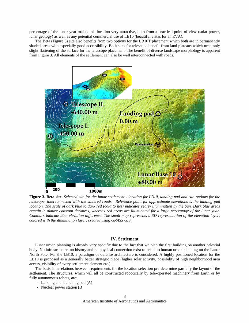
The North Pole seems to be a more favorable location. Three potential sites were examined (Alpha, Beta and
Gamma) on the North Pole (Figure 2). The Beta site was selected due to its proximity to the Lunar North Pole, the
only site that satisfies the 0.2° constraint for the latitude distance from the Pole. Additionally, the wide diversity of
the lunar landscape around the North Pole coupled with the prominent lunar cliff which is illuminated for a large
American Institute of Aeronautics and Astronautics
8
percentage of the lunar year makes this location very attractive, both from a practical point of view (solar power,
lunar geology) as well as any potential commercial use of LB10 (beautiful vistas for an EVA).
The Beta (Figure 3) site also benefits from two options for the LB10T placement which both are in permanently
shaded areas with especially good accessibility. Both sites for telescope benefit from land plateaus which need only
slight flattening of the surface for the telescope placement. The benefit of diverse landscape morphology is apparent
from Figure 3. All elements of the settlement can also be well interconnected with roads.
Figure 3. Beta site. Selected site for the lunar settlement - location for LB10, landing pad and two options for the
telescope, interconnected with the sintered roads. Reference point for approximate elevations is the landing pad
location. The scale of dark blue to dark red (cold to hot) indicates yearly illumination by the Sun. Dark blue areas
remain in almost constant darkness, whereas red areas are illuminated for a large percentage of the lunar year.
Contours indicate 20m elevation difference. The small map represents a 3D representation of the elevation layer,
colored with the illumination layer, created using GRASS GIS.
IV. Settlement
Lunar urban planning is already very specific due to the fact that we plan the first building on another celestial
body. No infrastructure, no history and no physical connection exist to relate to human urban planning on the Lunar
North Pole. For the LB10, a paradigm of defense architecture is considered. A highly positioned location for the
LB10 is proposed as a generally better strategic place (higher solar activity, possibility of high neighborhood area
access, visibility of every settlement element etc.)
The basic interrelations between requirements for the location selection pre-determine partially the layout of the
settlement. The structures, which will all be constructed robotically by tele-operated machinery from Earth or by
fully autonomous robots, are:
- Landing and launching pad (A)
- Nuclear power station (B)

American Institute of Aeronautics and Astronautics
9
- Lunar Base 10 (D)
- Telescope (C)
- Roads connecting base with landing and launching pad, with telescope and power station
The deployment of such a large settlement in the polar region requires a high number of mission elements to be
ready on the lunar orbit and on the lunar surface. The lunar surface in this mission scenario is required to be
prepared (flattened) and equipped with paths connecting areas of the lunar settlements prior to the crew arrival.
Additionally, the main structures of the LB10 require moving and compacting of a large amount of regolith for
covering the structures for radiation, micrometeoroid protection, and for extraction of lunar resources. Heavy
machinery such as scrapers, regolith transporters, bulldozers, and rovers that can be tele-operated will be necessary
for performing such a complex construction mission30.
A. Landing Pad
Landing pad will be the first structure of the settlement built and it will be gradually upgraded during the
construction process (Figure 3). The first lunar lander should have the capability to self-unload and self-deploy the
payload (rovers, machinery for construction). These will be designated construction machinery, tele-operated from
the Earth and whose task will be to flatten the area for landing and construct the landing surface. Later, the landing
pad will provide options for assisted unloading or passive lander with machinery (crane) payload unload support and
also a shelter for hardware and protective barriers31.
B. Power Station
The Nuclear Power station will be the second large component of the settlement built. It is proposed to serve as a
parallel source of energy to the solar energy utilized by every settlement element. The station is located on the path
between the LB10 and landing site (Figure 3). The power plant is buried under a thick layer of regolith inside a
small crater. A small fission system is proposed for construction and initiation of the base. Fission Surface Power
(Figure 4) can supply base and the landing site with 40 kW of electrical power for 8 years32. In case the solar power
generated is not sufficient, one or more reactors of this type or even more advanced and powerful reactors would be
added.
A separated small power system is proposed for the telescope. The telescope structure will need power for the
initial deployment. During the telescopes lifetime, power is needed for spinning the primary mirror and data
recording. A passive thermal control system should be implemented. The power system proposed for the telescope is
Radioisotope Thermoelectric Generator (RTG). Most recent type of RTGs can produce 300 W of electrical power33.
The location for this small power station is indicated in Figure 15.
Figure 4. Fission Surface Power system capable of generating 40 kW32
.
C. Lunar Base 10
The mass of the LB10 module was estimated to be at least 10 tons (landing mass) which needs to be delivered to
the polar region. As mentioned in the introduction, currently there is no launcher available which could fulfill the
requirements. By the time this project is in an advanced phase of design and the required technology is developed,
sometime in 2030s, there should be different launchers available which are able to do the task. New launch vehicle
American Institute of Aeronautics and Astronautics
10
proposals e.g., RUS-M family launchers may include of a variant that could launch up to 50 tons to LEO. This
launcher size could be promising for this goal*.
LB10 is the only habitable structure of the entire settlement. The area surrounding the LB10 is planned to be
equipped with a number of structures, mostly created using a sintering process. Sintering is a part of an ISRU
process, which uses lunar regolith as a construction material. Regolith solidification can be realized through bonding
of regolith particles below the melting point by emitting directed microwave radiation or by heating and pressurizing
the regolith. This process is a construction technique that is unique to the lunar environment. Fast solidification of
the lunar dust is possible mainly thanks to the very thin atmosphere on the Moon and the high abundance of iron in
the lunar dust. The sintering may be performed in a number of layers according to power source capacity or
technique used34. The surface layer can also be melted to create a glass-like surface and become easily cleanable
from lunar dust35. The sintering technique will be essential for lunar settlement construction. A well designed
robotic vehicle enabling moving and sintering of the regolith36† is essential.
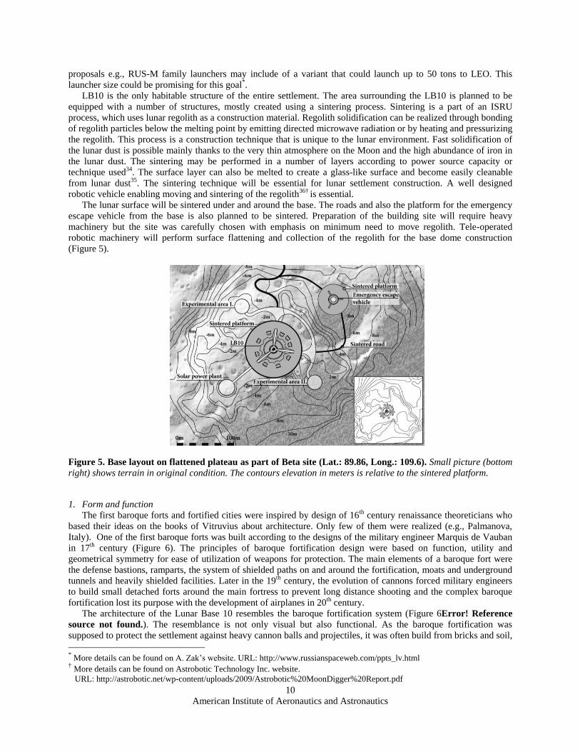
The lunar surface will be sintered under and around the base. The roads and also the platform for the emergency
escape vehicle from the base is also planned to be sintered. Preparation of the building site will require heavy
machinery but the site was carefully chosen with emphasis on minimum need to move regolith. Tele-operated
robotic machinery will perform surface flattening and collection of the regolith for the base dome construction
(Figure 5).
Figure 5. Base layout on flattened plateau as part of Beta site (Lat.: 89.86, Long.: 109.6). Small picture (bottom
right) shows terrain in original condition. The contours elevation in meters is relative to the sintered platform.
1. Form and function
The first baroque forts and fortified cities were inspired by design of 16th century renaissance theoreticians who
based their ideas on the books of Vitruvius about architecture. Only few of them were realized (e.g., Palmanova,
Italy). One of the first baroque forts was built according to the designs of the military engineer Marquis de Vauban
in 17th century (Figure 6). The principles of baroque fortification design were based on function, utility and
geometrical symmetry for ease of utilization of weapons for protection. The main elements of a baroque fort were
the defense bastions, ramparts, the system of shielded paths on and around the fortification, moats and underground
tunnels and heavily shielded facilities. Later in the 19th century, the evolution of cannons forced military engineers
to build small detached forts around the main fortress to prevent long distance shooting and the complex baroque
fortification lost its purpose with the development of airplanes in 20th century.
The architecture of the Lunar Base 10 resembles the baroque fortification system (Figure 6Error! Reference
source not found.). The resemblance is not only visual but also functional. As the baroque fortification was
supposed to protect the settlement against heavy cannon balls and projectiles, it was often build from bricks and soil,
* More details can be found on A. Zak‟s website. URL: http://www.russianspaceweb.com/ppts_lv.html
† More details can be found on Astrobotic Technology Inc. website.
URL: http://astrobotic.net/wp-content/uploads/2009/Astrobotic%20MoonDigger%20Report.pdf

American Institute of Aeronautics and Astronautics
11
composed in extremely thick walls which would absorb the cannon projectile impact. The configuration of baroque
fortification was based on pure geometry which goal was to create an impenetrable wall, with no mean of access for
the enemies and enabling crossfire on enemies from the occupants of the fortress.
Figure 6. Original plan of a baroque fortress Neuf Brisach near Strasbourg, France. Designed by Sébastien Le
Prestre de Vauban, Louis XIV's chief military engineer*.
The LB10 architecture is designed in a similar sense; the only difference being that the cannon projectiles are
substituted by radiation and flying meteorites. The base is located very near to the North Pole where the sun “travels
in the sky” 360° around the base. The base structure is thus supposed to provide a safe haven from all sides with
emphasis on protection against horizontal solar radiation. The structure also takes into account the difference in
inclination of the sun (± 5.2°) from which the most dangerous radiation may be emitted in the time of high solar
activity (solar flares). The small architectural elements surrounding the base, resembling detached bastions in
baroque architecture, are small shields against the above mentioned radiation threats. They should provide
occasional protection to vehicles or astronauts in EVA suits in case of unexpected events from any side around the
base. These detached elements are functionally inverted baroque bastions. As the baroque bastions in the
fortification wall were preventing access to the base enabling crossfire, the inverted bastions are supposed to enable
access to the base providing protection. The LB10 forms a star-like configuration of a real fortress on the Moon and
it honorably adopts principles of baroque architecture as one of the most powerful architecture styles in the history
of humankind.
2. Deployment and construction
Robotic construction techniques and possibilities were reviewed prior to the base design. Deployable structures
as a part of the lander, inflatable structures and regolith structures were selected for their high volumetric efficiency
regarding the delivery to the Moon.
To enable construction on a grand scale on the Moon, a lunar base requires also a well assessed risk of human
activities and operations in this hostile environment. Students of the ISU M.Sc. program in 2008 developed an
internationally integrated risk matrix and decision tree system for assessment of every task which could be
performed regarding exterior lunar operations and further supplementing these tasks by a robotic system. This study
also shows possible effective utilization of a variety of robotic systems according to environmental conditions, risk
and activity which have to be performed. Generally, any activity on the lunar surface can be performed robotically
with either a fully, partially autonomous robotic system or with a tele-operated robotic system from the Earth18. The
NASA Robotics, Tele-Robotics and Autonomous Systems Roadmap also suggests that robotics and tele-robotics are
proposed for space missions, not only for reduction of the risk but especially for reduction of the cost of human
spaceflight, with particular emphasis on robotics autonomy which would save time for tele-operation12. The authors
* The Triumph of Baroque Architecture in Europe 1600-1750. Retrieved 3, 26, 2011, from National Gallery of Art :
http://www.nga.gov/exhibitions/2000/baroque/indepth6.shtm

American Institute of Aeronautics and Astronautics
12
of this paper thus suggest that the entire lunar settlement presented should be constructed without human presence
on the Moon18.
To implement the robots for preparation and construction of the settlement site, it is suggested to use semi-
autonomous robots. This is due to various technical difficulties, such as communication latency (more than 3
seconds)37 and window contact duration. A framework for semi-autonomous tele-operation of multiple cooperative
robots for lunar exploration was proposed by D. Lee and M. W. Spong in 2005. This framework can be applied to
the presented concept38. The proposed framework (Figure 7) consists of two control loops, a local autonomous
control and integral communication node on the Moon and a bilateral tele-operation loop which enables humans to
remotely control operations38. Before the execution of a task, a strategic planning of each action is necessary.
Finally, before execution of each command, the command has to be verified by a responsible executing system on
the lunar site37.
This approach could be implemented during phase A and after human settlement is ready for its inhabitants, the
rovers could be controlled from the base while they still communicate with each other (Figure 7).
Figure 7. Proposed multiple robots control strategy framework.
Total habitable volume of the LB10 after full deployment is composed of a rigid core and inflatable torus
volume (2000 m3) and small cylindrical inflatable elements (each 120 m3) attached to the torus at the circumference.
The radial configuration enables easy access to the central core and the vertical communication with the airlocks on
top of the base. The habitat structure is folded as a single payload, designed for a payload shroud of 17 m tall and
American Institute of Aeronautics and Astronautics
13
5.4 m in diameter (similar to the Ariane V shroud). It also utilizes the aerodynamic shroud cap, which is usually
ejected and burns in the atmosphere, as part of the solar concentrator structure. The deployable solar concentrators
may be in the design supplemented by solar arrays – both options are possible though with a slightly different
technical solution and different power outputs. The concentrators are composed of metal mirrors and light structure
carrying a thin boom with triple junction solar cells on which the solar flux is concentrated. Both elements are
integrated on the inner side of the payload shroud and need to be deployed in order to be activated. One of the two
concentrators will be always idle while the other one will be directed to the sun. The entire structure (both
concentrators) will revolve to follow the sun.
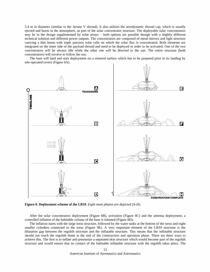
The base will land and start deployment on a sintered surface which has to be prepared prior to its landing by
tele-operated rovers (Figure 8A).
Figure 8. Deployment scheme of the LB10. Eight main phases are depicted (A-H).
After the solar concentrators deployment (Figure 8B), activation (Figure 8C) and the antenna deployment, a
controlled inflation of the habitable volume of the base is initiated (Figure 8D).
The inflation starts with the large torus structure, followed by the water tanks at the bottom of the torus and eight
smaller cylinders connected to the torus (Figure 9E). A very important element of the LB10 structure is the
dilatation gap between the regolith structure and the inflatable structure. This means that the inflatable structure
should not touch the regolith dome at the end of the construction and operation phase. There are three ways to
achieve this. The first is to inflate and pressurize a separated skin structure which would become part of the regolith
structure and would ensure that no contact of the habitable inflatable structure with the regolith takes place. The

American Institute of Aeronautics and Astronautics
14
second option is to over-pressurize the habitable inflatable skin for the period of regolith dome construction. The last
option is to over-pressurize the inflatable water tanks under the torus in such a way as to lift up the torus and create a
temporary form for the regolith dome construction. The inflatable torus will be lowered by depressurizing the tanks
and creating the necessary few centimeters dilation gap between the two structures (regolith-torus), just after the
regolith works are finished. These gaps are designed for insulation purposes (vacuum as perfect insulation) and to
protect the inflatable structure against abrasion during the dynamic loading of the structure caused by movement of
people inside the habitat.
Figure 9. Numerically calculated stress and deformation values of the structure loaded by internal
overpressure of 1 bar. The structure deformations are full-scale. The color contours display the course of principal
stresses in the structure. The scale is in MPa. The figure, calculations and explanation provided by Vratislav
Šálený, Sobriety s.r.o.
The “daring” design of a very large light-weight inflatable habitat structure utilizes a few tenths of a millimeter
thick membrane, which separates the interior microclimate of the habitat, with terrestrial-like atmosphere, from the
surrounding very thin atmosphere of the Moon. The proverbial life in a bubble is proposed to be tried out in practice.
This very thin inflated membrane will provide a self-supporting habitat structure, to which load-bearing floors
are anchored. Feasibility of this design has been verified successfully by stress-deformation numerical calculations.
The Finite Element Method using MSC.NASTRAN* code has been applied. Geometrically nonlinear force transfer
in the structure has been taken into account (solution NASTRAN SOL106†). The membrane has been modeled using
shell elements (SHELL4‡).
Initial calculations have been made within the framework of a preliminary study that did not involve any
structure dimensioning and therefore some inputs have been simplified. The computations have been based only on
a linear elastic material model with Young‟s modulus E = 131 GPa (Kevlar). For the same reason, the membrane
thickness has uniformly been set to 1 mm for the whole structure. Calculations have been made for a model
* NASTRAN - NASA STructure Analysis (NASA registered trademark) † SOL106 - nonlinear static solver in NASTRAN ‡ SHELL4 - Four node thin shell element in NASTRAN

American Institute of Aeronautics and Astronautics
15
consisting of a single symmetrically repeated structural element, a wedge with an angle of 22.5°. Symmetric
boundary conditions have been set for the element edges.
The results revealed no fundamental deformation or strength problems of such a structure (Figure 9). However,
they raised some issues to be solved in the next design and structure dimensioning phase, such as:
1. High local stress values on the edges of the communication tunnel between the torus and the capsule, which
could be solved by lining the opening in the skin with a thicker layer of material.
2. Corrugating of the skin in the vicinity of the torus inner radius, where the fabric-based material is subjected
to compression in the radial direction, forming ripples (analogy of stability loss in thin-walled structures).
This problem can be solved by optimizing the shape (“cut”) of the elements from which the torus will be
“sewn together“ in such a manner that after being pressurized the skin will be stretched tight in the radial
direction.
3. Reducing the skin weight of the inflatable structure by proportionally changing the membrane thickness
according to the magnitude of local stresses in the skin – most of the skin will have a thickness of the order
of tenths of a millimeter.
The habitat will be made of modern, high-strength materials such as Kevlar. Its mass will be optimally
distributed throughout the structure. Based on this computational study, it can now be assumed that the final,
optimized design of an inflatable habitat conceived this way should be able to fulfill the required functions, given by
the architectural design. The total weight of the entire inflatable structure should be less than 1000 kg. Therefore it
could be packaged in the confined payload shroud of the launcher as indicated in (Figure 8).
Figure 10. Plan of the LB10 at the ground level. Bastion elements placed radially around the base and three
ramps constructed for independent access to the base entrance.
Next step of the base construction is to cover the base with regolith for which heavy machinery on the lunar
surface will be needed. The regolith will be formed in 45° and 60° walls in two layers with one horizontal
intermission in the middle of the structure forming a so called “inspection level”. The regolith dome constructed in
this way will protect its inhabitants with a minimum of 2 meters of sintered regolith. This layer should be sufficient
protection against solar flares and micrometeorites39.
INVERTED BASTION
ACCESS RAMP
SAFETY AREA BEHIND BASTION
EMERGENCY KIT

American Institute of Aeronautics and Astronautics
16
The regolith is laid in two layers. The first layer is 1.5 m (Figure 8F) and is sintered only a few centimeters
below the surface. The second layer (Figure 8G) will be compacted and sintered in full depth (or according to
technical capabilities). The surface is finished as a glass-like surface with possibility of robotic implementation of
solar cells on the whole surface of the base (Figure 11).
The composition and design of the base regolith exterior includes also inverted bastions (Figure 10). As already
mentioned, the shaping of the walls and bastions is based on the geometry of the radiation impact angles and the
mass required for protection of a person inside the base or a person who accidentally stayed outside the base in case
of solar flare events (Figure 8H). The space behind the bastion has to be easily accessible and therefore the bastion is
inverted. The baroque bastions were built to prevent access in the vicinity of the fort. The inverted bastions serve the
opposite. They enable access to the base. In the niche behind each regolith inverted bastion, emergency oxygen
tanks and other backup gear for use in case of accident or prolonged EVA are located. Small protective elements
similar to bastions, also in form of little bunkers, will be constructed and sintered along the roads enabling
immediate cover in case of radiation or impact danger during transport between the settlement locations.
The base is equipped with three independent access ramps at the top, where the airlocks and base entrance are
located (Figure 10). These ramps are constructed along with other sintered regolith works. One small scientific
airlock is placed on ground level for delivery of geological samples to the base for research. This small 2 m diameter
airlock with 1 m ports will also serve as the emergency airlock, in case the main entrance on top of the base is
inaccessible.
Figure 11. Section of the LB10 with the main types of structures indicated in color.
3. Base Layout
The base main entrance is from the top, where three deployable airlocks, each pointed on one of the access
ramps, are located. The ramps may have dedicated transport systems or may be used for crew / rover access. The
base is designed with horizontal paths in the middle and on top for robotic arms. These arms may serve for
maintenance, manipulation or placement of experiments on the base walls. Generally, the exterior robotic arms
should minimize necessary EVAs and mitigate the risk. The top layer of the LB10 regolith shell will be later
sintered to glass like surface and will be ready for placement of the solar cells. This construction will also be
performed by robotic arms.

American Institute of Aeronautics and Astronautics
17
The access through one of three airlocks which serve also as dust locks, leads to a vertical core with an elevator
platform. In case of elevator malfunction, the core is equipped with foldable spiral staircase in the core walls. The
base is divided by structural separation in 3 different habitable interior areas plus airlocks as seen in Figure 14.
Private access area, public access area and specialized area with limited access (laboratories, controls, storage)
The torus is split in two levels where the top deck, accessible from the central core, is public. There is common
space dedicated to gardens, dining area with a bar and solitaire tables and chairs for relaxing or research on the outer
perimeter of the torus (Figure 12). There are 170 m2 dedicated to the elevated gardens which may be extended if
more levels for plant beds are added. These gardens function as an important element in the partially closed loop life
support system of the base. The products from the gardens serve only as partial or supplemental supply of food and
oxygen in the overall base system. The entire base design is only partially closed loop regarding the ECLSS,
although the air supply and regeneration is proposed to be fully independent. The ECLSS systems for atmosphere
regeneration are installed and delivered to the base separately and placed in the vertical rigid structures (Figure 11,
indicated in blue in Figure 12).
Figure 12. Plan of the top deck of the base. Elevated gardens are indicated in green. They are part of the partially
closed loop base system.
The bottom deck of the torus is dedicated to different functions such as commander‟s desk, control of the base,
scientific research but also to public gathering and access to vertical communication shaft. The division between
commercial, base operations and science areas is indicated in Figure 13.
Immediate access to the smaller private or specialized spaces placed radially around the main volume of the base
(Figure 14) is from the bottom deck. There are five “double room” capsules with private bathrooms which are
connected to an inflatable water/waste water collection system under the torus. Each capsule is split horizontally “in
two rooms”. These private rooms would be used for private activities but also for work. Quite a large capsule space
enables also storage of personal spacesuits in areas along the wall. Only two of these private capsules are primarily
dedicated to the permanent crew of 4 astronauts operating the base and performing scientific research. The other 3
are dedicated to pre-trained lunar tourists or commercial scientists. Renting the three habitable capsules to 6 people
in total should support the base operations costs in the long term.
Three other capsules are dedicated to specialized functions (Figure 14). One of them serves as storage for food,
base consumables, maintenance parts and ECLSS consumables. The second is connected to a small airlock for fast
transport of scientific samples inside the base. This capsule is split also in two levels where the top floor is a clean
laboratory with robotic arm controller and the bottom is a “dirty” laboratory for manipulation, experiments and
storing of geological samples. The airlock also serves as an emergency airlock in case of inaccessibility of the main
base entrance. A sintered tunnel out of the base is prepared for the small inflatable airlock. The entry of the tunnel is
protected by the configuration of inverted bastions to prevent especially the horizontal solar radiation from accessing
the tunnel interior. The geological samples are supposed to be delivered to the base robotically. The third room is the
medic‟s room and life science laboratory. The long term effects of reduced gravity on the human body are unknown.
Therefore the life science laboratory will serve for regular physiological and psychological examinations of the
LB10 crew.
Function m2 Sq ft
Elevated Garden 120 1292
Bar, Dining 35 377
Public 90 969
Core communication 17 183
Total 262 2821

American Institute of Aeronautics and Astronautics
18
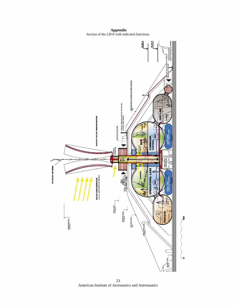
Figure 13. Section of the LB10 with the main functions described. See Appendix for larger drawing.
Figure 14. Plan of the LB10 bottom deck with indicated functions and space separation (dashed line).
American Institute of Aeronautics and Astronautics
19
D. Telescope
The lunar telescope with 20 m liquid mirror is operated as part of the settlement and will be placed farther from
the base in the indicated location (Figure 3 and Figure 15), to acquire observation data without disturbances from
human activities or devices. The telescope is designed as a deployable, inflatable structure that autonomously lands
in a selected location where tele-operated machinery has prepared the landing surface. The surface will be scraped
and sintered into a horizontal flat surface without dust particles
There are two locations proposed for the telescope. The first is inside a small (150 m diameter) crater
approximately 4 km from the base which is the nearest location with permanently shadowed conditions from the
base. The second is about 5 km from the base in a nearby permanently dark valley (Figure 3). The first location is
very suitable for a good access path and for a natural shield created by the optimal crater size for the 20 m telescope.
Nevertheless, more illumination and terrain data is needed to evaluate whether the crater will be well suitable
especially regarding the height of the crater‟s rim and height of the telescope. An additional lightweight sunshield
may need to be deployed for the telescope‟s secondary mirror in location I, or it can be landed at the telescope
location II.
The telescope location I crater was also selected for its perfectly flat bottom where the telescope module will
perform pin-point landing on a sintered plateau. The plateau will be connected with the landing site by a sintered
road (path) for robotic access regarding maintenance and collection of data. The telescope will require also a small
power station which is located outside the crater along the sintered path.
Figure 15. Telescope location I with additional sintered structures. The coordinates of the crater are Lunar Lat.:
89.90, Lunar Long.: 147.34.
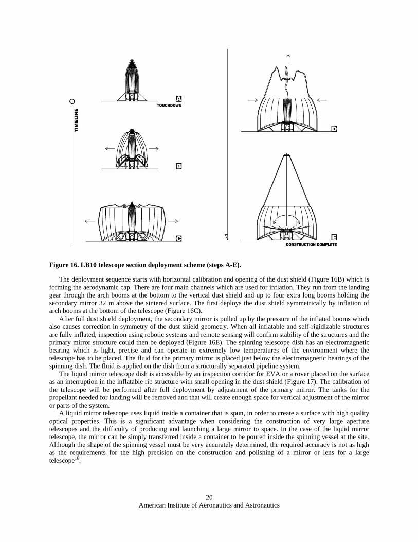
The telescope is folded in one payload shroud of 17 m tall and 5.4 m in diameter (same dimensions as the LB10).
The deployment sequence will start after propelled touchdown, pin-point landing on the sintered plateau inside the
crater (Figure 16A). The telescope module contains also a landing gear with propulsion tanks and engines for soft
landing. The mass of the landed payload is estimated to be 4 tons16. Therefore for such a large structure a number of
critical components are designed to be made of inflatable self-rigidizable material to achieve as low mass as possible
and small, launch-efficient shape for low volume stowage40. The inflatable telescope structures were well tested and
proven feasible and effective even for large space structures41.
American Institute of Aeronautics and Astronautics
20
Figure 16. LB10 telescope section deployment scheme (steps A-E).
The deployment sequence starts with horizontal calibration and opening of the dust shield (Figure 16B) which is
forming the aerodynamic cap. There are four main channels which are used for inflation. They run from the landing
gear through the arch booms at the bottom to the vertical dust shield and up to four extra long booms holding the
secondary mirror 32 m above the sintered surface. The first deploys the dust shield symmetrically by inflation of
arch booms at the bottom of the telescope (Figure 16C).
After full dust shield deployment, the secondary mirror is pulled up by the pressure of the inflated booms which
also causes correction in symmetry of the dust shield geometry. When all inflatable and self-rigidizable structures
are fully inflated, inspection using robotic systems and remote sensing will confirm stability of the structures and the
primary mirror structure could then be deployed (Figure 16E). The spinning telescope dish has an electromagnetic
bearing which is light, precise and can operate in extremely low temperatures of the environment where the
telescope has to be placed. The fluid for the primary mirror is placed just below the electromagnetic bearings of the
spinning dish. The fluid is applied on the dish from a structurally separated pipeline system.
The liquid mirror telescope dish is accessible by an inspection corridor for EVA or a rover placed on the surface
as an interruption in the inflatable rib structure with small opening in the dust shield (Figure 17). The calibration of
the telescope will be performed after full deployment by adjustment of the primary mirror. The tanks for the
propellant needed for landing will be removed and that will create enough space for vertical adjustment of the mirror
or parts of the system.
A liquid mirror telescope uses liquid inside a container that is spun, in order to create a surface with high quality
optical properties. This is a significant advantage when considering the construction of very large aperture
telescopes and the difficulty of producing and launching a large mirror to space. In the case of the liquid mirror
telescope, the mirror can be simply transferred inside a container to be poured inside the spinning vessel at the site.
Although the shape of the spinning vessel must be very accurately determined, the required accuracy is not as high
as the requirements for the high precision on the construction and polishing of a mirror or lens for a large
telescope16.

American Institute of Aeronautics and Astronautics
21
Figure 17. Section and plan of the LB10 telescope. Deployed and folded configuration - the payload shroud of
Ariane V was chosen as an example of a future heavy lift launcher.

American Institute of Aeronautics and Astronautics
22
V. Conclusions
This interdisciplinary concept study brings new ideas for planning permanent human settlements driven by the
requirements for placement and operation of a lunar liquid mirror telescope. The entire settlement and its
construction expect mature construction and deployment techniques which are currently not on a very high
technology readiness level but all of them are known and being tested. The entire settlement is proposed to be
constructed robotically and the construction will be operated from the Earth. The first crew should land on flat and
sintered landing pad connected with LB10 and power station by a sintered road. The next steps for the first crew
would be full initiation of the base systems and finishing of the furnishing and equipping of the base interior. The
interior equipment and systems would be delivered to the base also robotically including manipulation through the
airlocks. Advanced robotics thus plays very important role in this mission scenario without which the base could not
be constructed. The utilization of heavy machinery is driven by minimizing the risk of human operations in a hostile
environment18.
The paper also presents an architectural study of a base with a large astronomical observatory. The base planning
is heavily influenced by the presence of the instrument. The deployment and manufacturing methods presented in
this paper aim to add another small layer to the research done for such an instrument. Even though the exact form of
the observatory is yet to be developed, the novel methods presented here can hopefully be the start of a more
detailed analysis. The coupling of the architectural vision with the scientific desire can benefit both concepts by
exposing them to the capabilities and limitations of both fields.
The authors hope that this paper will help to advance the decade‟s long struggle to establish a base on the
Moon and by providing the innovative concept of LB10 and a new scenario; we also hope to motivate more research
and applications directed to the construction of lunar settlements.
American Institute of Aeronautics and Astronautics
23
Appendix Section of the LB10 with indicated functions.

American Institute of Aeronautics and Astronautics
24
Acknowledgments
The authors of this study would like to extend their thanks to: Vratislav Šálený and Sobriety s.r.o. company for
support and cooperation on the structural analysis and calculations of the Lunar Base 10 inflatable structures; Benoît
Hérin, ISU ESA YGT for support in preliminary engineering calculations and design; Cristine Barber (ISU) for
proofreading the report. This research has made use of the USGS Integrated Software for Imagers and Spectrometers
(ISIS). Lunar image processing was done using GRASS GIS for terrain display and analysis. Quantum GIS was
used for printing of lunar maps.
References 1Benaroya, H., Lunar Settlements, CRC Press, Taylor & Francis Group, Boca Rota, 2010, pp 19-33.
2Mankins, John C., “Modular Architecture Options for Lunar Exploration and Development,” IAA.13.2.05, 51st
International Astronautical Congress, Rio de Janeiro, Brazil. October 2-6, 2000, Paris, France, IAA. 3Howe, A. S., Gibson, I., ”MOBITAT2: A Mobile Habitat Based on the Trigon Construction System”, 2nd International
Space Architecture Symposium , AIAA 2006-7337, San Jose, California, USA, 2006 4Howe, A. S., Sherwood, B., Out of This World: The New Field of Space Architecture, Published by AIAA, 2009, pp 212-227
5Bodkin, D. K., Bocam, K. J., “A Human Lunar Surface Base and Infrastructure Solution” AIAA 2006-7336. 2nd
International Space Architecture Symposium (SAS 2006), AIAA Space 2006 Conference & Exposition, San Jose, California,
USA, 19-21 September 2006. Reston, Virginia, USA: American Institute of Aeronautics and Astronautics. 6Benaroya, H., Lunar Settlements, CRC Press, Taylor & Francis Group, Boca Rota, 2010, pp 387-400. 7SICSA, “The Manned Lunar Outpost (MLO): NASA/USRA-Sponsored Study”, SICSA Outreach, Vol. 2, No. 4, Oct-Dec.,
1989. 8Howe, A. S., Sherwood, B., Out of This World: The New Field of Space Architecture, Published by AIAA, 2009, pp 190-
196. 9Seedhouse, E.,Lunar Outpost,Springer-Verlag GmbH, Praxis, 2008. 10Roberts, M., “Inflatable Habitation for the Lunar Base”, N93-17442 [online archive] NASA Johnson Space Center,
Houston, 1993, URL: http://www.nss.org/settlement/moon/library/LB2-303-InflatableHabitation.pdf [cited 3 February 2010]. 11Benaroya, H., “An Overview of Lunar Base Structures: Past and Future”, AIAA Space Architecture Symposium, [online],
10-11 October 2002, Houston, URL: http://www.spacearchitect.org/pubs/AIAA-2002-6113.pdf [cited 8 January 2010]. 12NASA Office of The Chief Technologist (OCT), “Space Technology Roadmaps (DRAFT)”, Space Technology Roadmaps,
URL: http://www.nasa.gov/offices/oct/home/roadmaps/index.html, [cited February 2011]. 13Gardner, J. P., John C. M., Clampin M., Doyon R., Greenhouse M. A., Hammel H. B., Hutchings J. B. and collaborators,
“The James Webb Space Telescope,” Space Science Reviews, Vol. 123, Issue 4, November 2006 ,pp. 485-606. 14Spudis, P. D., Lavoie T., “Mission and Implementation of an Affordable Lunar Return.” Space Manufacturing (to be
published) 15Dudley-Rowley, M., Whitney, S., Bishop, S., Caldwell, B., Nolan, P. D., Gangale, T., “Crew Size, Composition, and Time:
Implications for Exploration Design,” AIAA 1st Space Architecture Symposium, Houston, pp 3-13, 2002. 16Angel, R., Worden, S. P., Borra, E. F., Eisenstein, D.J., Foing, B., Hickson, P., Josset, J., Ma, K.B., Seddiki, O.,
Sivanandam, S., Thibault, S., van Susante, P., “A Cryogenic Liquid-Mirror Telescope On The Moon To Study The Early
Universe, ” The Astrophysical Journal, Vol 680, Issue 2, pp 1582-1594, 2008. 17Jablonski, A. M., Ogden, K. A.,"A Review Of Technical Requirements For Lunar Structures - Present Status," International
Lunar Conference 2005. 18Mulugeta, L, Doule, O, Bodkin, D., Jagula, D., Quémet, L., Turnock, M.,Chan, A., Chasseigne, R., Demel, M., Hochsteiin,
J., Oprong, A., Salazar, J.P, "Astronaut Safety on the Moon", Space Times, Vol 48 , Issue 3, pp. 4-8., 2009. 19Sherwood, B., "Lunar Architecture and Urbanism 2d edition", 35th International Conference on Environmental Systems
(ICES), Rome, Italy, SAE 2005-01-2914, 2005. 20Eckert P, " Atracting Private Investment for Lunar Commerce - Toward Economically Sustanable Development," Lunar
Settlements, edited by Benaroya H, Boca Raton, CRC Press, Chapter 7, 2010. 21LROC Team, “NAC Polar Mosaics”, LROC images online archive , URL:
http://wms.lroc.asu.edu/lroc/nac_polar_mosaic, NASA/GSFC/Arizona State University, [last accessed March 2011]. 22Robinson, M., “LRO MOON LROC 5 RDR V1.0”, LRO-L-LROC-5-RDR-V1.0, NASA Planetary Data System (PDS),
2011. 23Neumann, G.A., “2009 Lunar Orbiter Laser Altimeter Raw Data Set”,LRO-L-LOLA-4-GDR-V1.0, NASA Planetary Data
System (PDS), 2010. 24Geographic Resources Analysis Support System (GRASS GIS) Software, GRASS Development Team, Open Source
Geospatial Foundation version 6.4,USA, 2010. 25Quantum GIS Development Team, ”Quantum GIS Geographic Information System” Open Source Geospatial Foundation
Project, version 1.6, 2010. 26Ruess, F., Braun, B., Zacny, K., Pinni, M.,"Lunar Base Site Preparation", Lunar Settlements, edited by Benaroya H, Boca
Raton: CRC Press, Chapter 32, 2010.

American Institute of Aeronautics and Astronautics
25
27Garrick-Bethell, I., Byrne S., Hoffman J. A., Zuber M. T., “Areas of favorable illumination at the lunar poles calculated
from topography,” 36th Annual Lunar and Planetary Science Conference, League City, Texas, abstract no. 2006, 2005. 28Bussey, D. , Lucey, P.G., Steutel, D., Robinson, M. S., Spudis, P.D., Edwards, K. D., “Permanent shadow in simple craters
near the lunar poles.,” Geophysical Research Letters, Vol 30, Issue 6, pp1-11, 2003. 29Foing, B., “The moon as a site for astronomy and space science,” Advances in Space Research, vol. 14, no. 6, p. (6)9-
(6)18, 1994. 30Benaroya, H., Lunar Settlements, CRC Press, Taylor & Francis Group, Boca Rota, 2010, pp 19-33. 31Smith, D., Woodcock, G., "Lunar Surface Systems and Operations for an Early Human Outpost," Space Technology and
Applications International Forum – STAIF, Arlington, American Institute of Physics, AIP Conference Proceedings, Vol 969, pp
699-708 , 2008. 32Poston, D. I., Kapernick, R. J., Dixon, D. D.; Amiri, B W.; Marcille, T F., " Reference Reactor Module for the Affordable
Fission Surface Power System," Space technology and applications international forum- STAIF, AIP Conference Proceedings,
American Institute of Physics, Volume 969, pp. 277-284, 2008. 33 Bennett, G. L., Lombardo J. J., Hemler R. J., Silverman, G., Whitmore, C.W., Amos, W. R., Johnson, E.W., Schock, A.,
Zocher, R. W., Keenan, T. K., Hagan, J. C., Englehart, R. W., “Mission of Daring: The General Purpose Heat Source
RadioisotopeThermoelectric Generator,” Proceedings of the 4th International Energy Conversion and Engineering Conference,
San Diego, CA, AIAA–2006–4096 June 26–29, 2006. 34Pletka, B., Resources of Near Earth Space, Processing of Lunar Basalt Materials, Danvers, University of Arizona Press,
1993. 35Wilson, T. L., Wilson K.B., "Regolith Sintering: A Solution to Lunar Dust Mitigation?," 36th Annual Lunar and Planetary
Science Conference, League City, Texas, abstract no.14222005, 2005. 36Taylor, L. A., Meek T., "Microwave Sintering of Lunar Soil: Properties, Theory, and Practice," Journal of Aerospace
Engineering, Vol 18, Issue 3 , pp. 188-196., 2005. 37Wright R. J., “Challenges in Robotic and Robot-Assistive Activities on the Moon and Mars”. Retrieved 3, 27, 2011, URL:
http://www-dial.jpl.nasa.gov/public_html/john/papers/ICRA_Rome/Final_Version.pdf , [last accessed March 2011]. 38Lee, D., Spong, M., "Semi-Autonomous Teleoperation of Multiple Cooperative Robots for Human-Robot Lunar
Exploration," Proceedings of AAAI Spring Symposium, 2006 39Lindsey, N., "Lunar Station Protection: Lunar Regolith Shielding," International Lunar Conference, Session5: Science Of,
From and On the Moon:Life Sciences and Habitation, Hawai, 2003. 40Fang, H.,Lou, M., Huang, J., Hsia, L. M., Kerdanyan, G.,"An Inflatable/Self-Rigidizible Structure for the Reflectarray
Antenna",10th European Electromagnetic Structures Conference, Munich, Germany, Pasadena: NASA JPL TRS 1992+, 2001. 41Scarborough, S., Cadogan D.,"Applications of Inflatable Rigidizable Structures," Society for Advancement of Material and
Process Engineering, Frederica, ILC Dover LP, DE 19946, 2006.