a machine learning based visible light …
TRANSCRIPT
A MACHINE LEARNING BASED VISIBLE LIGHT COMMUNICATION
MODEL LEVERAGING COMPLEMENTARY COLOR CHANNELby
Ruizhe Jiang
A Thesis
Submitted to the Faculty of Purdue University
In Partial Fulfillment of the Requirements for the Degree of
Master of Science in Electrical and Computer Engineering
School of Engineering Technology
Indianapolis, Indiana
August 2020
THE PURDUE UNIVERSITY GRADUATE SCHOOL
STATEMENT OF COMMITTEE APPROVAL
Dr. Brian King, Co-Chair
Department of Electrical and Computer Engineering
Dr. Xiaonan Guo, Co-Chair
Department of Computer Information and Graphics Technology
Dr. Xiao Luo
Department of Computer Information and Graphics Technology
Approved by:
Dr. Brian King
Head of the Graduate Program
2

ACKNOWLEDGMENTS
I wish to gratefully acknowledge my thesis committee for their insightful comments and
guidance and my family for their support and encouragement.
3
TABLE OF CONTENTS
LIST OF TABLES . . . . . . . . . . . . . . . . . . . . . . . . . . . . . . . . . . . . . 5
LIST OF FIGURES . . . . . . . . . . . . . . . . . . . . . . . . . . . . . . . . . . . . 6
LIST OF ABBREVIATIONS . . . . . . . . . . . . . . . . . . . . . . . . . . . . . . . 7
ABSTRACT . . . . . . . . . . . . . . . . . . . . . . . . . . . . . . . . . . . . . . . . 8
CHAPTER 1. INTRODUCTION . . . . . . . . . . . . . . . . . . . . . . . . . . . . . 9
CHAPTER 2. RELATED WORK . . . . . . . . . . . . . . . . . . . . . . . . . . . . . 12
CHAPTER 3. SYSTEM OVERVIEW . . . . . . . . . . . . . . . . . . . . . . . . . . . 14
3.1 Background . . . . . . . . . . . . . . . . . . . . . . . . . . . . . . . . . . . 14
3.2 System Flow . . . . . . . . . . . . . . . . . . . . . . . . . . . . . . . . . . . 15
CHAPTER 4. SYSTEM FLOW . . . . . . . . . . . . . . . . . . . . . . . . . . . . . . 18
4.1 Multi-Frequency and Multi-Phase Shift Keying Modulation . . . . . . . . . . . 18
4.2 Correlation-based Multi-phase Demodulation Scheme . . . . . . . . . . . . . . 20
4.3 Learning-based Demodulation Scheme . . . . . . . . . . . . . . . . . . . . . . 21
CHAPTER 5. PERFORMANCE EVALUATION . . . . . . . . . . . . . . . . . . . . . 23
5.1 Prototype Implementation and Evaluation Method . . . . . . . . . . . . . . . . 23
5.2 Experimental Evaluation . . . . . . . . . . . . . . . . . . . . . . . . . . . . . 24
5.2.1 Experimental Setup . . . . . . . . . . . . . . . . . . . . . . . . . . . 24
5.2.2 Performance using different videos . . . . . . . . . . . . . . . . . . . 24
5.2.3 Performance under different grid sizes . . . . . . . . . . . . . . . . . . 25
5.2.4 Performance under different distances between screen and camera . . . 27
CHAPTER 6. SUMMARY, CONCLUSION, AND RECOMMENDATIONS . . . . . . . 29
REFERENCES . . . . . . . . . . . . . . . . . . . . . . . . . . . . . . . . . . . . . . 30
4
LIST OF TABLES
4.1 Bit Segment-Frequency Mapping with Gray Coding(4-digit symbol) . . . . . . . . 19
4.2 Bit Segment-Frequency Mapping with Gray Coding(5-digit symbol) . . . . . . . . 19
5
LIST OF FIGURES
3.1 Demonstration of System Flow . . . . . . . . . . . . . . . . . . . . . . . . . . . 17
4.1 Demodulation process using both correlation and learning-based method . . . . . . 22
5.1 Performance using different types of video as data carrier. . . . . . . . . . . . . . . 25
5.2 Accuracy with different grid sizes. . . . . . . . . . . . . . . . . . . . . . . . . . . 26
5.3 Throughput with different grid sizes. . . . . . . . . . . . . . . . . . . . . . . . . . 27
5.4 Performance under different distances between transmitter and receiver. . . . . . . . 28
6
LIST OF ABBREVIATIONS
abbr abbreviation
bcf billion cubic feet
BMOC big man on campus
AT Aviation Technology
BCM Building and Construction Management
CGT Computer Graphics Technology
CIT Computer and Information Technology
CoT College of Technology
ECET Electrical and Computer Engineering Technology
MET Mechanical Engineering Technology
TLI Technology Leadership and Innovation
7
ABSTRACT
Recently witnessed a great popularity of unobtrusive Visible Light Communication (VLC)
using screen-camera channels. They overcomes the inherent drawbacks of traditional approaches
based on coded images like bar codes. One popular unobtrusive method is the utilizing of
alpha channel or color channels to encode bits into the pixel translucency or color intensity
changes with over-the-shelf smart devices. Specifically, Uber-in-light proves to be an successful
model encoding data into the color intensity changes that only requires over-the-shelf devices.
However, Uber-in-light only exploit Multi Frequency Shift Keying (MFSK), which limits the
overall throughput of the system since each data segment is only 3-digit long. Motivated by
some previous works like Inframe++ or Uber-in-light, in this thesis, we proposes a new VLC
model encoding data into color intensity changes on red and blue channels of video frames.
Multi-Phase-Shift-Keying (MPSK) along with MFSK are used to match 4-digit and 5-digit long
data segments to specific transmission frequencies and phases. To ensure the transmission
accuracy, a modified correlation-based demodulation method and two learning-based methods
using SVM and Random Forest are also developed.
8
CHAPTER 1. INTRODUCTION
Recently, device-to-device communication using visible channel gains great popularity due
to the widely use of screen and camera-equipped devices. A typical example is bar-code based
method that embeds information into 2D labels, which gains wide exploitation in daily life such
as the share of information or the tracking and classification of merchandises. In addition, many
works have also been conducted to improve bar-codes based methods to boost the throughput over
original media content. However, the capacity of bar-code based methods is limited due to the
small screen size and low camera. Under most of the conditions, they have to reduce the size of
codes to avoid influencing the normal viewing experience of audiences.
Due to the limitations of QR code, people tend to find new approaches in the field of
unobtrusive communications using visible channel. Typical instance include unobtrusive bar
codes[13] or embedding images/watermark into bar codes. However, the generation of such special
barcodes requires large time and space complexity, which means devices or facilities with high
CPU and GPU performance need to be exploited. Also, the cost of transmitting large amount of
data using such devices is large. Both of which limits the prevalent of such approaches.
Since QR code based methods have inherent limitations, some new approaches without
QR code are developed. Two typical examples are HiLight[7] and InFrame++[12]. Both of
them exploit the Persistence of Vision[3] characteristics of human visual system to ensure the
unobtrusiveness of communication using visible channel. Additionally, both of the approaches
embeds data as slight luminance differences over the color channel or alpha channel of a given
video. However, the system design and hardware requirements of Hilight limit the overall accuracy
and throughput of the model. For InFrame++, though it boost the throughput and accuracy by using
color channels as transmission channel, the system need to use high-level devices with a frame rate
of 120FPS as the transmitter and receiver, which is hard to be satisfied in daily life.
To overcome the limitation of high-end device, Uber-in-light [6] improves the structure
of HiLight and requires only over-the-shelf devices as the transmitter. Uber-in-light first divides
input streams into 3-bit long data units, each unit is mapped to a specific transmission frequency,
which is encoded as periodic luminance differences on red and blue color channels of the frames
in a given video. The receiver uses cameras with a frame rate of 30FPS to capture the video,
9
detecting small luminance changes that cannot be perceived by human eyes and extracting it as
continuous signals by calculating the differences on color channels of adjacent frames. Finally
a cross correlation-based scheme is developed for demodulation, which compare the extracted
signals with 8 templates representing 8 different frequencies used during transmission to recover
the original bit stream. The proposed model reached an accuracy of more than 90%. However,
Uber-in-light only exploit frequency during transmission to specify different signals and each
signal can only present a 3-digit long data segment, which in turn influences the overall throughput
of the model. In addition, the cross correlation method can only distinguish signals with different
frequencies, limiting its practicality under complex conditions.
As a result, we developed a novel visible light communication model using only basic
transmission and receiver devices. The new model is motivated by Uber-in-light. Like previous
works of Inframe++ and Uber-in-light, we encodes signals into small pixel luminance changes on
the original color channel of video frames. To overcome the limitation of the throughput using
MFSK, we exploit both Multi-Frequency Shift Keying (MFSK) and Multi-Phase Shift Keying
(MPSK), which enables signals carrying 4-digit or 5-digit data segments. Since signals in our
work differ in phases, demodulation method used in Uber-in-light is not available. To ensure the
robustness and accuracy of the demodulation process, we developed a modified correlation-based
demodulation method that can distinguish signals with different phases. To solve the limitation of
demodulation efficiency using correlation method, we also exploit some up-to-date learning-based
approaches to better classify signals with different frequencies and phases. The contributions of
this thesis can be concluded as follows:
• We developed a novel VLC model that exploits small changes in the color channels that
cannot be sensed by human eyes to convey data. We extend the length of each transmitted
bit unit by using Multi-Phase Shift Keying along with Multi-Frequency Shift Keying. Thus
the overall throughput is boosted since more bits are transmitted using longer data segment.
• We developed an improved correlation-based demodulation method. Traditional demod-
ulation method based on cross-correlation can only distinguish signals with different
frequencies and it cannot be used when MPSK is used. By improving the calculation method,
our improved scheme can distinguish signals with the same frequency but different phases.
10
• Aside from basic correlation-based method, we also exploit learning-based method in the
demodulation part to ensure the robustness of our new VLC model. We collected around
400k training data and trained two classification models using Support Vector Machine
(SVM) and Random Forest (RF). Experiments show that our learning-based methods
performed better comparing with correlation-based method.
The structure of the thesis is as follows: In Chapter II we mainly introduce related
works in the field of VLC, especially screen-camera-based VLC methods. In Chapter III, we
give some background information and the general overview of our new communication system.
Next, we describe the detail of our proposed system in Chapter 4, which include modulation and
demodulation parts. We then evaluate the performance of the new model by a series of experiments
under different conditions in Chapter 5. Finally, the conclusion of our work is in Chapter 6.
11
CHAPTER 2. RELATED WORK
The use of visible channel as the carrier to transmit data makes Visible light communi-
cation (VLC) receive increasing exploitation and research attention in recent years due to the
convenience and relatively low-cost. Generally, there are two types of VLCs: LED-based and
screen-camera-based. The former using the intensity of LED lights as the tool to modulate data
[2, 11]. The receiver will take photos of the transmitter to distinguish the states of each LED,
recovering the original data stream. The later encodes data into images or videos displayed on a
screen and use devices with camera to capture the image or frame, extracting data hidden inside
the media.
Due to the relatively low cost and high practicability, screen-camera-based VLC systems
has gained wide attentions recently. An intuitive approach is the use of visible coded images to
transmit data. Works like Lightsync[4] and Styrofoam[8] archived ideal performance the reliability
of transmission; Pixnet[10] can reach a relatively high throughput. There also exist some works
focusing on the security during transmission process like SBVLC[14]. Strata[5] and Bokode[9]
have high performance even at a relatively longer distance during transmission. Above all, VLCs
using visible coded images have relatively ideal performance on the throughput and accuracy of
transmission. Main drawback is that they need to spare space to display images with encoded data,
which has negative influence on the viewing experiences of the audiences.
As a result, unobtrusive screen camera communication emerges in order to deal with
the disadvantages in viewing experiences of systems using visible coded images. HiLight[7]
encodes data as slight luminance changes over the alpha channels in the frames of a given video.
However, the resolution of screen used to display the video and camera acting as the receiver
limit transmission accuracy and throughput of the system. Inframe++[12] is another example
that leverages subtle luminance changes on color channels of video frames to transmit data. The
changes cannot be perceived by human eyes due to the Persistence of Vision principle. Though
achieves relatively high accuracy and throughput, requirement of display devices with high frame
rate limit the practicability of the system.
Above all the unobtrusive screen camera communication models, Uber-in-light overcomes
the obstacle of devices[6]. It uses Multi-Frequency Shift Keying (MFSK) to match a specific
12
transmission frequency to a 3-digit long data segments and embedded the frequency as intensity
differences on color channels of video frames. The demodulation part first get the signals by
making subtractions on the color channels of adjacent frames. Then using a correlation-based
method to match each signal to a specific data segment, retrieving the original data stream.
However, Since only MFSK is used and the frame rate of receiver is limited to 30FPS, only 8
frequencies can be exploited as the transmission frequency, ranging from 7Hz to 14Hz due to the
limitation of Nyquist sampling principle, which restricts the overall throughput by limiting the
length of each data segment to 3-digit.
13
CHAPTER 3. SYSTEM OVERVIEW
This chapter mainly focuses on the basic structure of the new VLC model. We first give
a brief introduction of the human visual system and the principle of color perception of cameras.
Then we introduce the system workflow of our new method.
3.1 Background
The overall luminance of a specific pixel on display screens is contributed by three different
color channels representing the primary colors of red, green and blue. By changing the percentage
of each primary color, we get different colors showing on the screen. Generally, the three color
channels are orthogonal to each other and cannot be perceived independently unless watching
at a close distance. Thus, human eyes can only get an assured color when watching the screen
under daily environments. On the contrary, digital cameras are equipped with CMOS, which are
aggregation grids of a large number of sensors that can sense the luminance of three color channels
independently. Thus small luminance changes on the color channels that cannot be perceived by
human eyes can be captured and recognized by cameras, ensuring the possibility to hide data in
the color channels.
Furthermore, in a given video, there exists a time correlation between two adjacent frames,
which means the content in adjacent frames usually have little differences, Thus the luminance of
the two frames can also be regarded as the same. Such facts further proves the possibility to extract
the encoded data hidden inside the intensity changes of the color channels.
Based on all the facts above, Inframe++[12] and Uber-in-light[6] were developed. Both
of them exploit small luminance changes over color channels to convey bit streams. However,
Inframe++ requires devices with a frame rate as higher as 120FPS as the transmitter and receiver,
which limits its practicability. Specifically, Uber-in-light needs only over-the-shelf devices with
a frame rate of 30FPS as transmitter and receiver. It is composed by modulation part and
demodulation parts. During modulation process, it first divides input bit streams into 3-digit long
data units and matches a specific transmission frequency ranging from 7Hz to 14Hz to each data
unit. Then, it embeds signal with given frequency into the periodic color intensity changes of
video frames. Uber-in-light exploit red and blue channels as the carrier of signals since these
14
two channels have the least contribution to the overall luminance, ensuring the requirement of
unobtrusiveness. The system modifies the intensity of red and blue channels of the original video
frames with a small value of δ in an opposite manner, which means if the change on red channel
is δ , the change on blue channel is −δ accordingly. The goal of this manner is to ensure that
the signals can be extracted apparently during demodulation. To ensure the overall throughput,
Uber-in-light divide the screen used as transmitter into small grids to transmit data simultaneously,
each grid has the same number of pixels.
During demodulation, the receiver uses cameras with a frame rate of 30FPS to capture
the video, recognizing each grids before calculating the color intensity changes by subtract the
luminance of red and blue channels in two adjacent frames to get the hidden signals. Since the
modifications on red and blue channels are opposite to each other, the result of the subtraction
doubles the small change value of δ , ensuring that the extracted signal contents enough features
of frequency. Finally, a cross-correlation-based method is used to compare the received signals
with templates to get the transmission frequency, mapping it to a specific data unit to recover the
original bit streams. Main drawback of Uber-in-light is that it only exploit signals with different
frequencies as the transmission tool, limiting the overall throughput since only 8 frequencies can be
used due to the requirements of Nyquist sampling principle and each data unit is restricted to 3-bit
long. In addition, the cross-correlation demodulation method requires large amount of calculation
times, reducing the overall efficiency of the system.
3.2 System Flow
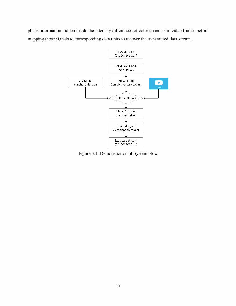
Our proposed model includes a transmitter (i.e., screen) and a receiver (i.e., camera). The
system flow is shown in Figure 3.1. Generally, there are two main tasks. The first is modulation,
which divides input streams into transmission units with certain length and encodes them into
video frames. The second is demodulation, which use cameras to capture the video with encoded
data and exploit demodulation algorithms to extract them.
Given an input bit stream, the transmitter will first modulate these bits. Uber-in-light only
exploits multi-frequency shift keying, where the input stream is divided into 3-digit long data units
and each unit is matched with a specific transmission frequency ranging from 7Hz to 14Hz. Our
improvement in modulation is that aside from MFSK, we also use Multi-Phase Shift Keying to
15
improve throughput, which means in addition to a specific transmission frequency, each data unit
is also mapped with a given transmission phase. As a result, 3-digit long data unit is not enough
since it can only demonstrate 8 categories and more digits are needed for signal data units to
represent phases, thus improve the overall throughput comparing with Uber-in-light by extending
the amount of transmitted bits for each unit. Our improved model can generate 4-digit and 5-digit
bit units, which represent 8 transmission frequencies along with two or four transmission phases
respectively. Each unit will be matched to a specific frequency and phase, which is the important
information to be exploited to generate transmission signals using luminance changes on the color
channels. Comparing with single MFSK, MFSK along with MPSK greatly improved the channel
capacity due to the extension of each data segment. Then, as in some previous works[6, 12], we
make small modifications on the intensity of color channels to encode data. Red channels along
with blue channels are exploited as the carrier during transmission since they together contribute
less than 30% to the overall luminance. We modified the luminance of the red and blue channels
according to the signals in an opposite manner (if δ is used for red channel, then −δ is used
for blue channel and vice versa). In addition, We generate synchronization waves by modifying
the intensity of green channel in respect to the frequency of the transmitted signals to ensure the
stability of the transmission as well as the requirement for unobtrusiveness.
During demodulation, the receiver will use camera to capture the video frames with data
hidden inside. The receiver will then recognize each color channel on all transmission grids and
detect the intensity differences. Traditional cross-correlation method mainly compare the signals
with templates representing different frequencies[6]. However, such correlation-based method
cannot distinguish signals with differences in phase since signals with the same frequency but
different phases will get the same correlation value with the template. Also, the comparison
will take large amount of calculation time, if 8 frequencies are used during transmission, the
system has to complete 8 comparisons for each signal, resulting in a decrease in the overall
efficiency of the whole system. To solve the first problem of the limitation in the classification
of multi-phase signals of cross-correlation, we first developed a modified correlation method that
can distinguish both different frequencies and phases. To deal with the relatively low efficiency
of correlation-based methods, we next trained a classification model using some popular machine
learning methods to improve the overall accuracy and robustness of identifying the frequency and
16
phase information hidden inside the intensity differences of color channels in video frames before
mapping those signals to corresponding data units to recover the transmitted data stream.
Figure 3.1. Demonstration of System Flow
17
CHAPTER 4. SYSTEM FLOW
We mainly introduce the detailed work flow and principles of our new model during this
chapter. In the basic work flow, the input bit stream is divided into data unit with certain length,
each unit is matched to a specific frequency and phase. We then use the frequency and phase to
embed signals into video frames by modifying the intensity of red and blue channels periodically.
The slight intensity changes on specific color channels will be captured and recognized by the
receiver side using both improved correlation-based method and learning-based frequency/phase
estimation algorithms, extracting the original input streams.
4.1 Multi-Frequency and Multi-Phase Shift Keying Modulation
At the transmitter side, we first divides the inputted bit stream into short data units. In
Uber-in-light, the length of each unit is set as 3-digit since it uses 8 transmission frequencies.
In our new model, since phase is also exploited during transmission, 3-digit long bit segment is
not enough. Thus, we use 4-digit data unit for 2-phase MPSK and 5-digit data unit for 4-phase
MPSK. Then, a specific signal pattern including a specific transmission frequency and phase will
be associated to each bit segment.
We first map a specific frequency to each data unit. The last 3 digits of the data segment are
associated with a specific frequency. Gray code is used since two adjacent frequencies only differ
in one bit, which lowers the influence of noise and interference. To fulfill the Nyquist sampling
principle, we choose 7Hz to 14Hz as the modulation frequency range[6].
To increase the overall throughput, we also exploit MPSK in our system that give each
data segment a specific phase along with the frequency. As is discussed above, MFSK method can
only handle 8 different data symbols, which represent 8 specific transmission frequencies and each
symbol is only 3-digit long. With the import of MPSK, we can improve the system throughput by
expanding the range of symbols as well as the length of each data unit. We use the first digit in
4-digit data units and first two digits in 5-digit data units to demonstrate the phase information. To
alleviate the possible influence of interference, we ensure that two successive phases have enough
distance between each other and gray code used in MFSK is also exploited. Generally, we use ±π2
18
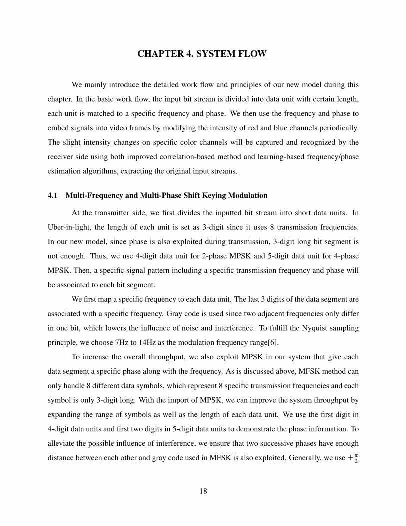
for 4-digit data unite and ±π2 , π and 0 for 5-digit data units. The detailed mapping to frequencies
and phases of each bit unit is demonstrated in Table 4.1 and Table 4.2.
Table 4.1. Bit Segment-Frequency Mapping with Gray Coding(4-digit symbol)
First digit Phase Last 3 digits Frequency (Hz) Last 3 digits Frequency (Hz)
0 π/2 000 7 001 8
1 -π/2 011 9 010 10
110 11 111 12
101 13 100 14
Table 4.2. Bit Segment-Frequency Mapping with Gray Coding(5-digit symbol)
First 2 digit Phase Last 3 digits Frequency (Hz) Last 3 digits Frequency (Hz)
00 π/2 000 7 001 8
01 -π/2 011 9 010 10
11 π 110 11 111 12
10 0 101 13 100 14
As in some previous works[6, 12], we make modifications to the intensity of color channels
to hide data inside the video frames. Generally, each color channel does not have the same
contribution to the overall luminance. Red channel and blue channel have a contribution of
21.26% and 7.22% respectively while green channel along has the highest contribution to the
overall luminance of 71.52%. Since red and blue channels contribute less comparing with green
channel, we tend to modify the intensity of them to make sure that the overall luminance differences
between frames cannot be perceived by human eyes. We then introduces a small parameter of δ as
the modification value on the red and blue channels. The modifications on these two channels is in
an inverse manner (if δ is used for red channel, then −δ is used for blue channel and vice versa)
to ensure the robustness of the signal extraction. The overall luminance changes is kept at a low
level of 0.4304 * δ , which ensures the requirement of unobtrusiveness. In addition, since devices
used as transmitter and receiver are not specifically designed for data transmission, we also exploit
the green channel as the synchronization channel to ensure the stability of the transmission. The
19
generation of the synchronization wave is the same as the encoding of data, where we modify the
intensity of green channels in respect to the frequencies of the transmitted signal.
4.2 Correlation-based Multi-phase Demodulation Scheme
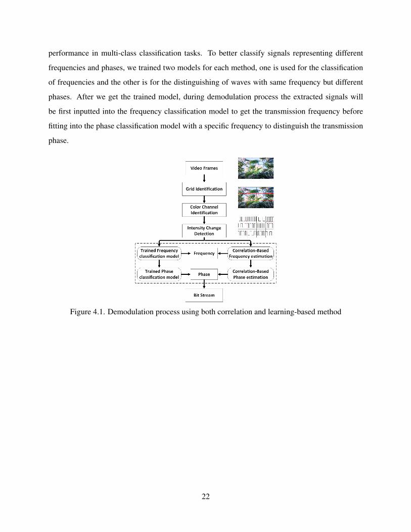
The detail of our demodulation scheme is demonstrated in Figure 4.1. The information of
the original signal is embedded in the video frames, thus we need to first extract those signals before
further decoding works. To ensure the overall throughput, the screen is divided into multiple grids
with same size performing parallel data transmission. Thus, the first step is to identify different
grids using a specific camera calibration methods [1]. Then the receiver get the intensity value of
each color channels in a specific transmission grid. Finally, for two adjacent frames Fk and Fk+1,
we calculate the color intensity changes between them. For a specific pixel at point (x,y), the
color intensity is (Rk,Gk,Bk) at Fk and (Rk+1,Gk+1,Bk+1) at Fk+1. We calculate the subtraction
of (Rk+1,Gk+1,Bk+1) - (Rk,Gk,Bk) to get the color differences on two adjacent frames on the
given pixel. The overall color intensity differences between two adjacent frames is achieved by
calculating the average value of (Rk+1,Gk+1,Bk+1) - (Rk,Gk,Bk) on all the pixels in a given grid.
The final color intensity differences is defined as D = δB − δR, since the modifications of the
intensity of red and blue channels are inverse to each other, this doubles our modification value of
δ in signal color channel, ensuring that the extracted signals contain enough features. We finally
assume D as a point in the received signal. The system keeps calculating the intensity changes
using the method above on the video stream and finally we achieve a continuous signal set with
each segment represents a specific bit symbol (e.g. 1001, 1000, 0011...).
The demodulation part in Uber-in-light exploit a cross-correlation-based method to identify
signals carrying different data segments, which calculates the cross-correlation value between the
received signals and a series of templates of the standard signals. However, such method can
only distinguish signals with different frequencies since phases with different phases but same
frequencies will get the same correlation value. Since our new method uses MPSK, we first
developed a modified correlation method that can handle signals with different phases. Given a
specific signal, we first use the tradition cross-correlation method to get the frequency. Supposing
the signal is xi, i = 0,1,2, ...,n and the template is yi, i = 0,1,2, ...,n, the cross-correlation value
can be denoted by Σni=0, j=0(xi ∗ y j). We calculate this value between the signal and all templates
20
demonstrating 8 frequencies to find the highest correlation value, which is the frequency of the
given signal. Then, we exploit a new formula to find the phase. Still denoting the signal and
template as xi, i = 0,1,2, ...,n and yi, i = 0,1,2, ...,n respectively, the Multi-phase correlation value
is calculated by Σni=0(xi∗yi). Since we already get the frequency of the given signal, this calculation
is done between the signal and templates with all the phases we used but share the same frequency
as the given signal.
4.3 Learning-based Demodulation Scheme
The modified correlation-based method is an easy way to make demodulation. However,
such method requires large amount of calculation. For each signal, the system need to compute
8 correlation values to find the frequency and 2 as well as 4 values to find the phase for 4-digit
and 5-digit data unit respectively, which means such approach is not efficiency enough. Thus, we
proposed to use up-to-date learning-based method to train a classification model to map the signals
into corresponding bit symbols. To ensure the robustness of the training process, we first collected
large number of signals achieved by the calculating of color intensity changes as the training set.
Totally, we used 200k training signals for each bit symbol length (4-digit and 5-digit long). The
training data is collected under different grid size, video contents and distance, covering a wide
range of conditions to ensure the robustness of the final classification model.
Since our system exploits only over-the-shelf devices, the low frame rate results in the
relatively short length of each signal segment, which is not enough for the training process. As
a result, we extend the information in training set by adding more features. We totally selected 3
features for each signal segment in the training set, including Fast Fourier Transformation (FFT),
self-correlation and mean. Generally, FFT can extract the hidden frequencies information of a
given signal while self-correlation demonstrate the self-similarity pattern of a wave and can extract
phase information. mean value can also demonstrate phase information since waves with different
phase but same frequencies have different mean values. Two popular machine learning methods
are exploited: Support Vector Machine (SVM) and Random Forest (RF). SVM is a basic learning
algorithm with relatively simple structure and fast calculation speed. Though originally developed
to deal with 2-class classifications, SVM is also widely used in multi-class classification tasks.
Random Forrest is a popular algorithm used in classification based on decision tree with ideal
21
performance in multi-class classification tasks. To better classify signals representing different
frequencies and phases, we trained two models for each method, one is used for the classification
of frequencies and the other is for the distinguishing of waves with same frequency but different
phases. After we get the trained model, during demodulation process the extracted signals will
be first inputted into the frequency classification model to get the transmission frequency before
fitting into the phase classification model with a specific frequency to distinguish the transmission
phase.
Figure 4.1. Demodulation process using both correlation and learning-based method
22
CHAPTER 5. PERFORMANCE EVALUATION
In this chapter, we mainly evaluate the performance of our new VLC system. Since the
light intensity change δ over red and blue channels in our model is set as δ = 0.8, which is the
same as Uber-in-light, we assume that the requirements of unobtrusiveness is fulfilled since the
evaluation of perception is already conducted in Uber-in-light[6]. We mainly evaluate the accuracy
and throughput using videos with various contains under different distance and grid sizes.
5.1 Prototype Implementation and Evaluation Method
The prototype of our new model contains transmitter and receiver sides, both are
implemented by C++ and OpenCV library. A bit stream and a video are inputted to the transmitter,
the transmitter divides it into data segments with certain length according to how many phases
are used during transmission. Then the transmitter embeds the data by modify the intensity of the
red and blue channels of the frame in respect to the mapped frequency and phase. The processed
video with hidden data inside is then played at the screen with a frame rate of 60FPS. The receiver
using over-the-shelf cameras with a frame rate of 30FPS to capture the frames, locates the screen
and transmission grids before extracting the color intensity changes and generating the signals
by calculating the differences on color channels. The training set of the learning-based signal
classification model is also collected by the receiver side and the learning-based model as well
as the training process are implemented by Python and Scikit-learn library. During real-time
transmission, our system will perform real-time playback with a frame rate of 60FPS, which is used
in our experiments to ensure that the receiver get enough features for each signal. Meanwhile, the
receiver extracted signals from the RB-channel and fit them into the trained classification model
concurrently to extract the embedded bit stream.
To completely evaluate the overall performance of our new model, we defined two
metrics: accuracy and throughput. Accuracy means the percentage of correctly transmitted bits
and throughput demonstrated the amount of correctly transmitted bits during one second. To
demonstrate our new model‘s improvements comparing with Uber-in-light, we also conduct some
experiments to compare the new model‘s performance with the experiment results of Uber-in-light.
23
5.2 Experimental Evaluation
5.2.1 Experimental Setup
The default settings of our experiments are set as follows. The devices used is the same as
in the experiment part in Uber-in-Light[6], with a Lenovo screen as the transmitter and a Samsung
Tablet as the receiver. All experiments were done in typical office environments during daytime.
Under default settings, the receiver is 40cm away from the transmitter, which is a common distance
when people using devices to take photos or videos. A same bit stream is generated by the system
for all the experiments as the input data to ensure the consistency. For each experiment condition
setting, we tested both 4-digit data symbol and 5-digit data symbol, which further classify 8FSK
signal into 2PSK and 4PSK signal respectively. All videos with embedded data are played with
720p HD resolution and a frame rate of 60FPS in full screen mode. The tests are done using
three demodulation methods: modified MPSK correlation method, SVM classification model and
Random Forest classification model. In general, correlation-based method achieves the lowest
performance in transmission accuracy and throughput due to the interference on the screen. Both
SVM and RF increase the overall accuracy and throughput comparing with correlation but the
improvement using SVM is only around 1%, this is because SVM is not originally designed for
multi-class classification tasks. Random Forest achieves the highest performance since it is a
robustness algorithm for classifications with more than two categories. The detailed experiment
results is clarified as follows.
5.2.2 Performance using different videos
Different video contents may influence the overall performance of our model since videos
with dynamic scenes tend to content more frame changes and interference while static videos
are much more stable for data transmission. We totally tested 6 types of videos with both
dynamic and static contents. Video types we used include TV drama, sport scenes, scenery clips,
desktop operation, game recording and static pictures, covering a wide range of hue, contrast
and conversion patterns of frames. We totally recorded 20 1-minute long videos for each video
types and we get the result by calculating the average value of them. Figure 5.1 demonstrates
the average accuracy and throughput. In our experiments, Random Forest method achieves the
24
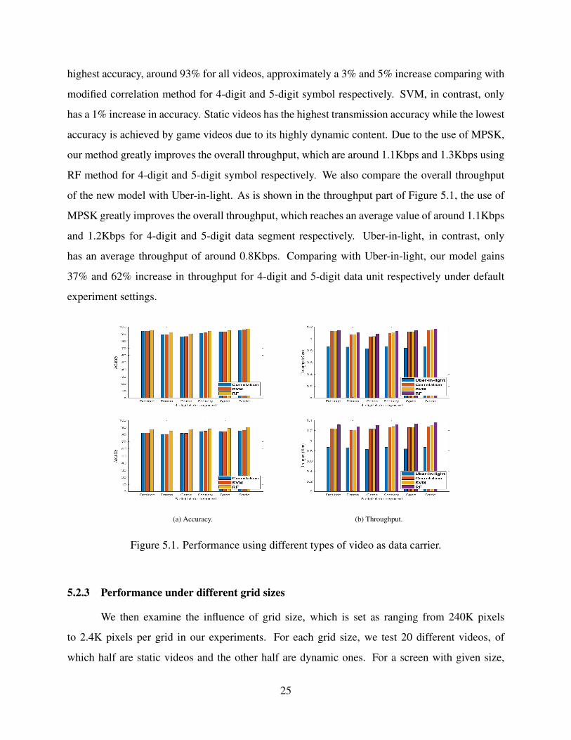
highest accuracy, around 93% for all videos, approximately a 3% and 5% increase comparing with
modified correlation method for 4-digit and 5-digit symbol respectively. SVM, in contrast, only
has a 1% increase in accuracy. Static videos has the highest transmission accuracy while the lowest
accuracy is achieved by game videos due to its highly dynamic content. Due to the use of MPSK,
our method greatly improves the overall throughput, which are around 1.1Kbps and 1.3Kbps using
RF method for 4-digit and 5-digit symbol respectively. We also compare the overall throughput
of the new model with Uber-in-light. As is shown in the throughput part of Figure 5.1, the use of
MPSK greatly improves the overall throughput, which reaches an average value of around 1.1Kbps
and 1.2Kbps for 4-digit and 5-digit data segment respectively. Uber-in-light, in contrast, only
has an average throughput of around 0.8Kbps. Comparing with Uber-in-light, our model gains
37% and 62% increase in throughput for 4-digit and 5-digit data unit respectively under default
experiment settings.
(a) Accuracy. (b) Throughput.
Figure 5.1. Performance using different types of video as data carrier.
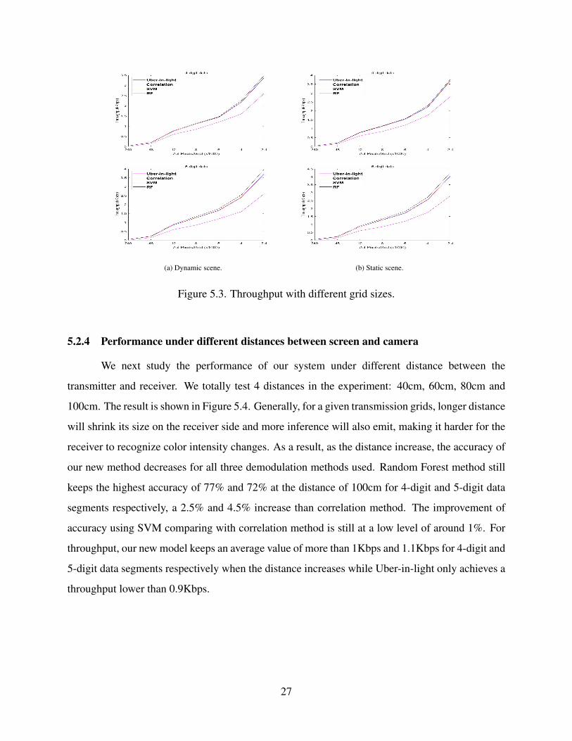
5.2.3 Performance under different grid sizes
We then examine the influence of grid size, which is set as ranging from 240K pixels
to 2.4K pixels per grid in our experiments. For each grid size, we test 20 different videos, of
which half are static videos and the other half are dynamic ones. For a screen with given size,
25
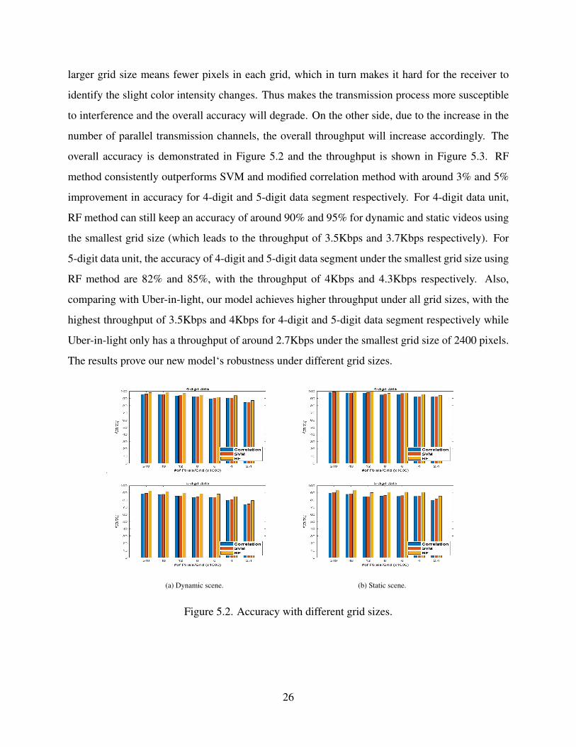
larger grid size means fewer pixels in each grid, which in turn makes it hard for the receiver to
identify the slight color intensity changes. Thus makes the transmission process more susceptible
to interference and the overall accuracy will degrade. On the other side, due to the increase in the
number of parallel transmission channels, the overall throughput will increase accordingly. The
overall accuracy is demonstrated in Figure 5.2 and the throughput is shown in Figure 5.3. RF
method consistently outperforms SVM and modified correlation method with around 3% and 5%
improvement in accuracy for 4-digit and 5-digit data segment respectively. For 4-digit data unit,
RF method can still keep an accuracy of around 90% and 95% for dynamic and static videos using
the smallest grid size (which leads to the throughput of 3.5Kbps and 3.7Kbps respectively). For
5-digit data unit, the accuracy of 4-digit and 5-digit data segment under the smallest grid size using
RF method are 82% and 85%, with the throughput of 4Kbps and 4.3Kbps respectively. Also,
comparing with Uber-in-light, our model achieves higher throughput under all grid sizes, with the
highest throughput of 3.5Kbps and 4Kbps for 4-digit and 5-digit data segment respectively while
Uber-in-light only has a throughput of around 2.7Kbps under the smallest grid size of 2400 pixels.
The results prove our new model‘s robustness under different grid sizes.
(a) Dynamic scene. (b) Static scene.
Figure 5.2. Accuracy with different grid sizes.
26
(a) Dynamic scene. (b) Static scene.
Figure 5.3. Throughput with different grid sizes.
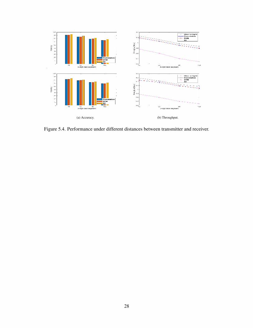
5.2.4 Performance under different distances between screen and camera
We next study the performance of our system under different distance between the
transmitter and receiver. We totally test 4 distances in the experiment: 40cm, 60cm, 80cm and
100cm. The result is shown in Figure 5.4. Generally, for a given transmission grids, longer distance
will shrink its size on the receiver side and more inference will also emit, making it harder for the
receiver to recognize color intensity changes. As a result, as the distance increase, the accuracy of
our new method decreases for all three demodulation methods used. Random Forest method still
keeps the highest accuracy of 77% and 72% at the distance of 100cm for 4-digit and 5-digit data
segments respectively, a 2.5% and 4.5% increase than correlation method. The improvement of
accuracy using SVM comparing with correlation method is still at a low level of around 1%. For
throughput, our new model keeps an average value of more than 1Kbps and 1.1Kbps for 4-digit and
5-digit data segments respectively when the distance increases while Uber-in-light only achieves a
throughput lower than 0.9Kbps.
27
(a) Accuracy. (b) Throughput.
Figure 5.4. Performance under different distances between transmitter and receiver.
28
CHAPTER 6. SUMMARY, CONCLUSION, AND RECOMMENDATIONS
In this thesis, we present a new screen-camera-based VLC system motivated by some
previous works like Uber-in-light or Inframe++. In addition to Multi-Frequency Shift Keying,
we exploit Multi-Phase Shift Keying to extend the length of each data unit to be transmitted,
thus increasing the capacity of each signal. To ensure our system‘s robustness in demodulation,
we develop a modified correlation-based method as well as learning-based methods on receiver
side as the tool to distinguish signals with different frequencies and phases. A SVM model and
a Random Forest model are trained using more than 200k data to classify signals and RF-based
model performed better with 3% and 6% increase in overall transmission accuracy in 4-digit and
5-digit data symbols respectively comparing with correlation-based demodulation method. Also,
our system achieves an average throughput of 1.1kbps and 1.3kbps for 4-digit and 5-digit long
data unit, a 37% and 62% increase comparing with the 0.8kbps throughput in Uber-in-light under
default experiment environments.
29
REFERENCES
[1] Gary Bradski. Opencv. Dr. Dobb’s Journal of Software Tools, 2000.
[2] Andrew Burton, Hoa Le Minh, Zabih Ghassemlooy, Sujan Rajbhandari, and Paul AnthonyHaigh. Performance analysis for 180r receiver in visible light communications. In 2012Fourth International Conference on Communications and Electronics (ICCE), pages 48–53,2012.
[3] Abbas Cheddad, Joan Condell, Kevin Curran, and Paul Mc Kevitt. Digital imagesteganography: Survey and analysis of current methods. Signal processing, 90:727–752,2010.
[4] Wenjun Hu, Hao Gu, and Qifan Pu. Lightsync: Unsynchronized visual communicationover screen-camera links. In Proceedings of the 19th Annual International Conference onMobile Computing and Networking, MobiCom13, page 1526, New York, NY, USA, 2013.Association for Computing Machinery.
[5] Wenjun Hu, Jingshu Mao, Zihui Huang, Yiqing Xue, Junfeng She, Kaigui Bian, and GuobinShen. Strata: Layered coding for scalable visual communication. In Proceedings of the 20thAnnual International Conference on Mobile Computing and Networking, MobiCom 14, page7990, New York, NY, USA, 2014. Association for Computing Machinery.
[6] Mostafa Izz, Zhongyuan Li, Hongbo Liu, Yingying Chen, and Feng Li. Uber-in-light:Unobtrusive visible light communication leveraging complementary color channel. InIEEE INFOCOM 2016 - The 35th Annual IEEE International Conference on ComputerCommunications, pages 1–9, 2016.
[7] Tianxing Li, Chuankai An, Xinran Xiao, Andrew T. Campbell, and Xia Zhou. Real-timescreen-camera communication behind any scene. In Proceedings of the 13th AnnualInternational Conference on Mobile Systems, Applications, and Services, MobiSys 15, page197211, New York, NY, USA, 2015. Association for Computing Machinery.
[8] Robert LiKamWa, David Ramirez, and Jason Holloway. Styrofoam: A tightly packed codingscheme for camera-based visible light communication. In Proceedings of the 1st ACMMobiCom Workshop on Visible Light Communication Systems, VLCS 14, page 2732, NewYork, NY, USA, 2014. Association for Computing Machinery.
[9] Ankit Mohan, Grace Woo, Shinsaku Hiura, Quinn Smithwick, and Ramesh Raskar. Bokode:Imperceptible visual tags for camera based interaction from a distance. ACM Trans. Graph.,28(3), July 2009.
[10] Samuel David Perli, Nabeel Ahmed, and Dina Katabi. Pixnet: Interference-free wireless linksusing lcd-camera pairs. In Proceedings of the Sixteenth Annual International Conference onMobile Computing and Networking, MobiCom 10, page 137148, New York, NY, USA, 2010.Association for Computing Machinery.
30
[11] Stefan Schmid, Giorgio Corbellini, Stefan Mangold, and Thomas R. Gross. An led-to-ledvisible light communication system with software-based synchronization. In 2012 IEEEGlobecom Workshops, pages 1264–1268, 2012.
[12] Anran Wang, Chunyi Peng, Ouyang Zhang, Guobin Shen, and Bing Zeng. Inframe:Multiflexing full-frame visible communication channel for humans and devices. InProceedings of the 13th ACM Workshop on Hot Topics in Networks, HotNets-XIII, page 17,New York, NY, USA, 2014. Association for Computing Machinery.
[13] Grace Woo, Andy Lippman, and Ramesh Raskar. Vrcodes: Unobtrusive and active visualcodes for interaction by exploiting rolling shutter. In 2012 IEEE International Symposium onMixed and Augmented Reality (ISMAR), pages 59–64, 2012.
[14] Bingsheng Zhang, Kui Ren, Guoliang Xing, Xinwen Fu, and Cong Wang. Sbvlc: Securebarcode-based visible light communication for smartphones. IEEE Transactions on MobileComputing, 15(2):432–446, 2016.
31