a mapping approach to investigating information and...
TRANSCRIPT

i
A Mapping Approach to Investigating Information and Communication Technology (ICT)
Implementation during the Building Design Process
A thesis submitted in fulfilment of the requirements for the degree of Doctor of Philosophy
Yi Li, Choong
School of Property, Construction and Project Management
Design and Social Context Portfolio RMIT University
March 2006

ii
Declaration I certify that except where due acknowledgement has been made, the work is that of the author alone; the work has not been submitted previously, in whole or in part, to qualify for any other academic award; the content of the thesis is the result of work which has been carried out since the official commencement date of the approved research program; and, any editorial work, paid or unpaid, carried out by a third party is acknowledged.
Yi Li, Choong 31st March 2006

iii
ACKNOWLEDGEMENT First of all, I would like to convey my sincere and heartfelt thank my supervisor, Dr Peter
Edwards, for his guidance, knowledge, enthusiasm, amazing teaching ability, and unfailing
confidence in me. Also his editorial comments were particularly valuable to me during the
dissertation writing process. I couldn't and wouldn't have don’t this research without him.
I am most grateful to my second supervisor, Dr Peter Stewart, for reviewing my thesis and for
his constructive criticism on all the topics, as well for his assistance in acquiring the IDEF0
software for my research.
Elizebeth Stewart generously offered training and advice on the IDEF0 software. Geoff
Outhred as consultant provided me with many valuable suggestions concerning the Delphi
survey process.
Much appreciation goes to the Delphi panel of experts who contributed their time and
thoughts to this research.
I am also grateful for the comments of staff in the School of Property, Construction and
Project Management for their contribution to my learning and research. The friends I made
during my PhD study were always very helpful and made the experience enjoyable one.
Finally, I would like to thank my family and friends, for their emphasis on education,
patience, encouragement, support and love.

iv
TABLE OF CONTENTS
ACKNOWLEDGEMENT .....................................................................................................................................III
TABLE OF CONTENTS .......................................................................................................................................IV
LIST OF FIGURES.............................................................................................................................................VIII
LIST OF TABLES..................................................................................................................................................IX
LIST OF ABBREVIATIONS.................................................................................................................................. 1
ABSTRACT............................................................................................................................................................... 1
1 INTRODUCTION........................................................................................................................................... 2
1.1 INTRODUCTION......................................................................................................................................... 2 1.2 RESEARCH AIM AND OBJECTIVES............................................................................................................ 2 1.3 RESEARCH QUESTION .............................................................................................................................. 3 1.4 MOTIVATION FOR THE RESEARCH ........................................................................................................... 4
1.4.1 The need to reduce the level of building design process fragmentation ........................................... 4 1.4.2 The Life Cycle Costing Logic............................................................................................................. 6 1.4.3 Inefficiencies of Information Management ........................................................................................ 7 1.4.4 Developments in Information and Communication Technology....................................................... 7
1.5 OUTLINE METHODOLOGY........................................................................................................................ 8 1.6 LIMITATION............................................................................................................................................ 11
2 LITERATURE REVIEW ............................................................................................................................ 13
2.1 INTRODUCTION....................................................................................................................................... 13 2.2 THE PROCESS OF BUILDING DESIGN ....................................................................................................... 13
2.2.1 Schematic Design Stage ................................................................................................................... 15 2.2.2 Design Development Stage............................................................................................................... 16 2.2.3 Documentation Stage ....................................................................................................................... 16
2.3 IDENTIFYING STRANDS .......................................................................................................................... 17 2.3.1 Design Communication .................................................................................................................... 17 2.3.2 Design Information Management .................................................................................................... 19 2.3.3 Information and Communication Technologies (ICT) .................................................................... 20 2.3.4 The Impact of Technology................................................................................................................ 44 2.3.5 The Challenges ................................................................................................................................. 47
2.4 PROCESS MAPPING................................................................................................................................. 49 2.4.1 Definition of Process ........................................................................................................................ 49 2.4.2 Process Mapping Methodology........................................................................................................ 49 2.4.3 The IDEF0 Approach ....................................................................................................................... 52 2.4.4 Models Review.................................................................................................................................. 57

v
2.5 SUMMARY .............................................................................................................................................. 66
3 IDEF0 MODEL DEVELOPMENT ............................................................................................................ 67
3.1 INTRODUCTION....................................................................................................................................... 67 3.2 MODEL CLASSIFICATION ....................................................................................................................... 67 3.3 MODEL DEVELOPMENT PROCESS .......................................................................................................... 69
3.3.1 Data Gathering Phase...................................................................................................................... 69 3.3.2 Process Map Structuring Phase....................................................................................................... 70 3.3.3 Map Documentation Phase .............................................................................................................. 70 3.3.4 Feedback Interaction Phase............................................................................................................. 71
3.4 THE PROPOSED MODEL.......................................................................................................................... 72 3.4.1 Assumptions to the model................................................................................................................. 72 3.4.2 Model Interpretation ........................................................................................................................ 73
3.5 DEFINITION OF RESEARCH VARIABLES ................................................................................................. 73 3.5.1 Feasibility Studies Stage (as Input) ................................................................................................. 73 3.5.2 Building Design Process (as Function) ........................................................................................... 74 3.5.3 Design process success (as Output)................................................................................................. 83 3.5.4 Improve communication (as Output) ............................................................................................... 83 3.5.5 Improve quality of Information Flow (as Output) ........................................................................... 84 3.5.6 Types of Procedures and Guidelines (as Control) .......................................................................... 84 3.5.7 Types of Requirements (as Control) ................................................................................................ 85 3.5.8 ICT Tools (as Mechanism) ............................................................................................................... 85 3.5.9 People (as Mechanism) .................................................................................................................... 85
3.6 SUMMARY .............................................................................................................................................. 87
4 RESEARCH METHODOLOGY & DESIGN........................................................................................... 89
4.1 INTRODUCTION....................................................................................................................................... 89 4.2 RESEARCH DESIGN JUSTIFICATION........................................................................................................ 90 4.3 DESIGN AND ADMINISTRATION OF THE DELPHI SURVEY ...................................................................... 91
4.3.1 The Delphi Process .......................................................................................................................... 93 4.3.2 Evaluation of Delphi ........................................................................................................................ 96 4.3.3 Objective of Delphi for this study .................................................................................................... 98 4.3.4 Internet-based DELPHI Survey ....................................................................................................... 99 4.3.5 Delphi Panel Selection Criteria ..................................................................................................... 100 4.3.6 Recruitment Procedure .................................................................................................................. 101 4.3.7 Description of the Delphi panel ..................................................................................................... 101 4.3.8 The Delphi Rounds ......................................................................................................................... 104
4.4 DATA ANALYSIS PROCEDURES............................................................................................................ 107 4.5 SUMMARY ............................................................................................................................................ 110

vi
5 DELPHI SURVEY: ANALYSIS AND RESULTS.................................................................................. 111
5.1 INTRODUCTION..................................................................................................................................... 111 5.2 DELPHI ROUND 1.................................................................................................................................. 111 5.3 DELPHI ROUND 2.................................................................................................................................. 116 5.4 DELPHI ROUND 3.................................................................................................................................. 122 5.5 DELPHI ROUND 4.................................................................................................................................. 131 5.6 SUMMARY ............................................................................................................................................ 144
6 DEVELOPMENT OF THE PROPOSED ICT IMPLEMENTATION MAP...................................... 145
6.1 INTRODUCTION..................................................................................................................................... 145 6.2 EXTRACTING BUILDING DESIGN ACTIVITIES & THEIR RELATIONSHIPS FROM IDEF0 MAP ............... 145 6.3 IDENTIFY RATING FOR EACH ACTIVITY............................................................................................... 149 6.4 IDENTIFY ISSUES FOR IMPLEMENTATION............................................................................................. 155 6.5 DEVELOPING THE ICT IMPLEMENTATION MAP.................................................................................... 157 6.6 SUMMARY ............................................................................................................................................ 160
7 VALIDATION OF THE BUILDING DESIGN PROCESS MAPS...................................................... 161
7.1 INTRODUCTION..................................................................................................................................... 161 7.2 THE INTERVIEWS.................................................................................................................................. 161
7.2.1 Interview Format ............................................................................................................................ 161 7.2.2 Interview Responses ....................................................................................................................... 162
7.3 THE MODIFIED MAPS........................................................................................................................... 168 7.4 SUMMARY ............................................................................................................................................ 171
8 CONCLUSIONS AND RECOMMENDATIONS................................................................................... 172
8.1 INTRODUCTION..................................................................................................................................... 172 8.2 SUMMARY OF MAIN FINDINGS.............................................................................................................. 172 8.3 RECOMMENDATIONS FOR PRACTICE.................................................................................................... 174 8.4 RECOMMENDATIONS FOR FUTURE RESEARCH .................................................................................... 175 8.5 ACHIEVEMENT OF RESEARCH OBJECTIVES ......................................................................................... 176
REFERENCES...................................................................................................................................................... 181
APPENDIX-A........................................................................................................................................................ 194
APPENDIX-B........................................................................................................................................................ 216
APPENDIX-C........................................................................................................................................................ 221
APPENDIX-D........................................................................................................................................................ 231
APPENDIX-E........................................................................................................................................................ 238
APPENDIX-F ........................................................................................................................................................ 244

vii
APPENDIX-G ....................................................................................................................................................... 250
viii
LIST OF FIGURES
FIGURE 1-1 RESEARCH QUESTIONS............................................................................................................................. 4 FIGURE 1-2 LIFE CYCLE COSTING (KIRK AND DELLISOLA, 1995).............................................................................. 6 FIGURE 2-1 THE ENCRYPTION/DECRYPTION PROCESS .............................................................................................. 31 FIGURE 2-2 ARROW POSITIONS AND ROLES (SOURCE: FIPS 183, 1993)................................................................... 54 FIGURE 2-3 CONTEXT DIAGRAM (SOURCE: GROUT, 1998) ....................................................................................... 54 FIGURE 2-4 DECOMPOSITION STRUCTURE (SOURCE: FIPS 183, 1993) ............................................................... 55 FIGURE 2-5 GENERIC DESIGN AND CONSTRUCTION PROCESS PROTOCOL (WWW.PROCESSPROTOCOL.COM) .......... 59 FIGURE 2-6 ANALYTICAL DESIGN PLANNING TECHNIQUE (ADEPT) (SOURCE: AUSTIN ET AL., 2002).................. 62 FIGURE2-7 REVISED VERSION OF THE PRELIMINARY CONCEPTUAL DESIGN FRAMEWORK MODEL ....................... 65 FIGURE 3-1 TOP LEVEL DIAGRAM FOR BUILDING DESIGN MANAGEMENT PROCESS (A-0 DIAGRAM) .................... 71 FIGURE 3-2 IDEF0 A0 DIAGRAM FOR BUILDING DESIGN MANAGEMENT PROCESS................................................ 75 FIGURE 4-1 FLOWCHART FOR THE DELPHI PROCESS (SOURCE: JOPPE, 2001) ......................................................... 95 FIGURE5-1 CURRENT AND FUTURE USAGE LEVEL OF ICT TOOLS DURING BUILDING DESIGN PROCESS .............. 120 FIGURE 5-2 COMPARISON OF CURRENT AND FUTURE RATING FOR ICT IMPLEMENTATION................................... 127 FIGURE 5-3 COMPARISON OF RATING ON CURRENT BARRIERS FOR ICT IMPLEMENTATION AND IN YEAR 2009. ... 130 FIGURE 6-1 ABSTRACTING RELATIONSHIPS BETWEEN ACTIVITIES FROM IDEF0 ARROW POSITIONS .................... 147 FIGURE 6-2 DRAFT MAP SHOWING RELATIONSHIPS BETWEEN DESIGN ACTIVITIES................................................. 148 FIGURE 6-3 FUTURE ICT TOOL IMPLEMENTATION FOR ACTIVITIES DURING THE BUILDING DESIGN PROCESS...... 151 FIGURE 6-4 CURRENT VS. FUTURE RATING ON ICT IMPLEMENTATION DURING BUILDING DESIGN PROCESS......... 154 FIGURE 6-5 MAP OF CURRENT ICT IMPLEMENTATION DURING THE BUILDING DESIGN PROCESS ................... 158 FIGURE 6-6 MAP OF FUTURE ICT IMPLEMENTATION DURING THE BUILDING DESIGN PROCESS ........................... 159 FIGURE 7-1 MAP OF ‘CURRENT’ ICT IMPLEMENTATION DURING THE BUILDING DESIGN PROCESS (54 BUILDING
ACTIVITIES EXTRACTING FROM IDEF0 MAP) ................................................................................................ 169 FIGURE 7-2 MAP OF ‘FUTURE’ ICT IMPLEMENTATION DURING THE BUILDING DESIGN PROCESS (54 BUILDING
ACTIVITIES EXTRACTING FROM IDEF0 MAP) ................................................................................................ 170 FIGURE 1 ARROW POSITIONS AND ROLES ............................................................................................................... 223 FIGURE 2 IDEF0 PARENT TO CHILD DIAGRAM NUMBERING (ACTIVITY TREE)...................................................... 223 FIGURE 3 TOP LEVEL DIAGRAM FOR BUILDING DESIGN MANAGEMENT PROCESS (A-0 DIAGRAM)...................... 224 FIGURE 4 IDEF0 A0 DIAGRAM FOR BUILDING DESIGN MANAGEMENT PROCESS ................................................. 225
Deleted: 230
Deleted: 230
Deleted: 231
Deleted: 232

ix
LIST OF TABLES
TABLE 5-1 DEMOGRAPHICS OF DELPHI SURVEY PANEL OF EXPERTS...................................................................... 113 TABLE 5-2 SUMMARY RESULT FOR ROUND 1 SECTION C: ADDITIONAL PROCESS ACTIVITIES SUGGESTED BY
PANELLISTS .................................................................................................................................................... 115 TABLE 5-3 CURRENT USAGE LEVEL OF ICT TOOLS TABLE 5-4 FUTURE USAGE LEVEL OF ICT TOOLS.............. 119 TABLE 5-5 VALUE ADDED ISSUES ON ICT APPLICATION DURING BUILDING DESIGN PROCESS -1/2 .................... 124 TABLE 5-6 VALUE ADDED ISSUES ON ICT APPLICATION DURING BUILDING DESIGN PROCESS -2/2 .................... 125 TABLE 5-7 BARRIERS FOR ICT IMPLEMENTATION DURING BUILDING DESIGN PROCESS ½................................... 128 TABLE 5-8 BARRIERS FOR ICT IMPLEMENTATION DURING BUILDING DESIGN PROCESS 2/2................................. 129 TABLE 5-9 CURRENT RATING FOR ICT USE DURING BUILDING DESIGN PROCESS (DELPHI ROUND 4) .............. 139 TABLE 5-10 COMPARISON OF RESULT FOR CURRENT ICT USAGE RATINGS FOR ROUNDS 1 - 4.......................... 140 TABLE 5-11 FUTURE RATING FOR ICT USE DURING BUILDING DESIGN PROCESS............................................... 142 TABLE 5-12 COMPARISON OF RESULT FOR FUTURE ICT USAGE RATINGS FOR ROUNDS 1 - 4 ............................. 143
1
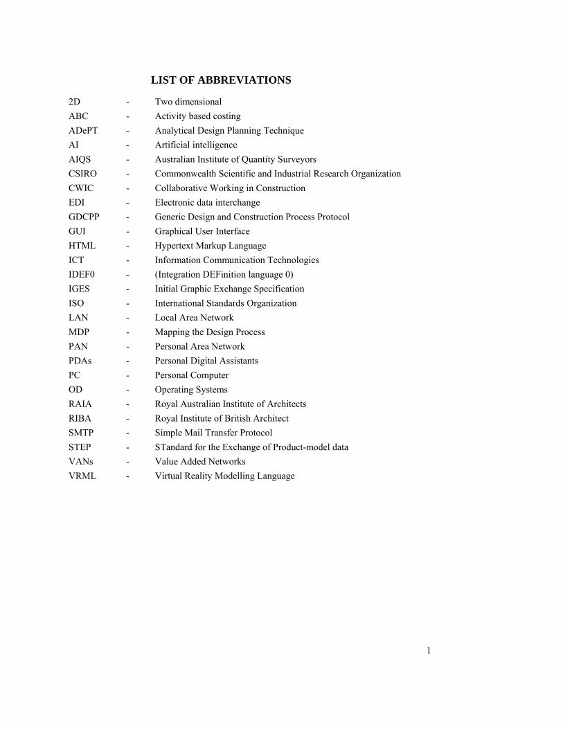
LIST OF ABBREVIATIONS
2D - Two dimensional ABC - Activity based costing ADePT - Analytical Design Planning Technique AI - Artificial intelligence AIQS - Australian Institute of Quantity Surveyors CSIRO - Commonwealth Scientific and Industrial Research Organization CWIC - Collaborative Working in Construction EDI - Electronic data interchange GDCPP - Generic Design and Construction Process Protocol GUI - Graphical User Interface HTML - Hypertext Markup Language ICT - Information Communication Technologies IDEF0 - (Integration DEFinition language 0) IGES - Initial Graphic Exchange Specification ISO - International Standards Organization LAN - Local Area Network MDP - Mapping the Design Process PAN - Personal Area Network PDAs - Personal Digital Assistants PC - Personal Computer OD - Operating Systems RAIA - Royal Australian Institute of Architects RIBA - Royal Institute of British Architect SMTP - Simple Mail Transfer Protocol STEP - STandard for the Exchange of Product-model data VANs - Value Added Networks VRML - Virtual Reality Modelling Language

1
ABSTRACT Building design is a complex process that involves multi-disciplinary professionals working
together throughout the multi-processes of a project. The success of this process is highly
dependent on effective communication and adequate information flow; any incorrect or
inadequate information flow will result in a failure in project management
Information and communication technologies (ICT) have been implemented and integrated
into many of the individual processes of building design, but little is known of the extent and
intensity of ICT implementation. Not is there any clear indication about where future
development might occur.
The purpose of this study is to develop and validate an ICT implementation map, focusing on
the usage level, the impact, barriers and other issues of ICT implementation during the
building design process for current practice, and to predict future trends over the following
five years (2005 to 2009).
Five “strands” for the research were identified and discussed: the existing information
management and communication during the building design process; to what extent design
professionals adopt ICT in their daily routine; the impact of technology; the barriers to the
implementation of technology; existing communication problems faced by design team
member during the building design process; and the techniques and tools used during the
building design process.
IDEF0 process mapping software was used to map the building design process for traditional
contract procurement projects (design-bid-construct). The process map was further tested by
four rounds of Delphi survey. Data collected from the four rounds of Delphi survey were
adapted in proposing an “ICT Implementation Map during the Building Design Process” (for
current usage and in five years time). The proposed ICT Implementation Map was tested and
further improved through interviews with three experts.
The findings of the research support its aim and objectives and demonstrate that advances in
technology have increased the efficiency and effectiveness of building design process
management. Moreover, the proposed maps provide a baseline for design professionals or
decision makers when asked to adopt new technologies to facilitate the design process.

2
1 INTRODUCTION
1.1 INTRODUCTION
Design is a process of human interaction and consequently the outcomes contain the
interpretations, perceptions and prejudices of the people involved (Gray and Hughes., 2001).
The building design process involves multi-disciplinary professionals working together
throughout the multi-processes of a project. Enormous amounts of data are generated during
the different stages of the design process, presented in drawings, specifications, bills of
quantities, and other construction documents. This information is transferred between
different project participants throughout the design and construction processes, thus effective
means of communication and information management are the keys to facilitating the success
of these processes and to eliminate some of the factors which can lead to project disputes.
While the quality of design has been shown to impact on all subsequent stages of a project’s
life cycle (Zaneldin, 2000), effective communication and adequate information flow are
critical to the success of a construction project; any incorrect or inadequate information flow
will result in a failure in project management (Munns and Bjeirmi, 1996).
The up-take rate of Information and Communication Technology (ICT) in Australia has been
among the best in the OECD according to Bennett et al. (2003). By adopting advanced
information and communication technology to facilitate the building design process, most
problems currently found in the process may be eliminated.
The purpose of this study is to develop and validate an ICT implementation map focusing on
the usage level, the impact, barriers and other issues of ICT implementation during the
building design process for current practice, and to predict future trends over the following
five years (2005 - 2009). Given the rate of technology change for ICT over the past four
decades, the period of prediction is a deliberately safe, conservative choice.
1.2 RESEARCH AIM AND OBJECTIVES
The aim of this research is to better understand how Information and Communication
Technology (ICT) is implemented during the building design process. The study involves
three objectives:

3
To examine the manner in which ICT is used by the building design professions
during the building design process, with a focus on large-scale office/commercial
projects in Australia.
To investigate and map existing design processes using the IDEF0 (Integrated
DEFinition) functional modelling technique.
To propose a best practice model for ICT implementation during the building design
process that improves information exchange and levels of communication between
participants.
1.3 RESEARCH QUESTION
While focused on the building design process occurring on large-scale office/commercial
building projects in Australia, this research is largely generic and will attempt to answer the
following questions (refer to Figure 1-1):
Research Question One - How can process mapping be used to describe and
document the building design process?
Research Question Two – What aspects of work done by design professionals are
influenced by ICT?
Research Question Three – How much do building design professionals use ICT
tools?
Research Question Four - What are the impacts of ICT implementation by building
design professionals during the design process?
Research Question Five - Can a best practice model be mapped for ICT use during
the design process?
Research Question Six - What is the future trend (over five years) of ICT
implementation during the building design process?

4
Figure 1-1 Research Questions
1.4 MOTIVATION FOR THE RESEARCH
The building design process for most large scale projects is highly fragmented, involving
many players from different professional disciplines who are brought together at different
stages throughout the procurement life cycle of unique projects. These professionals, due to
their different views of the building, describe it in different levels of detail. As a result, the
creation and use of information within the design become less homogenous and more
fragmented. Moreover, much of the wasted time and cost encountered in construction projects
can be traced back to poor information and communication – insufficient, inaccurate,
inconsistent, and late or combinations of all of these (Zaneldin, 2000). This research focuses
on the potential of developing a best practice ICT model for improving building design
management. Several aspects of the building design process have motivated the research,
including the need to reduce fragmentation; the logic of the project life cycle; the
inefficiencies of information management; and development in ICT.
1.4.1 The need to reduce the level of building design process fragmentation
Designing is a process of human interaction and consequently the outcomes contain the
interpretations, perceptions and prejudices of the people involved (Gray and Hughes, 2001).
Each designer will have different ideals and perceptions on his or her design, and
acceptability of the outcomes is based on the willingness of each individual to accept
modifications to those ideals and perceptions.
5
“The separation of design and construction processes, including the late involvement of
specialists and poor communication between design and construction teams, was all
identified as leading to inappropriate design solutions. Designers were criticised for having a
‘solo mentality’, a discomfort in reaching definitions, and for deliberately mystifying the
design process.”
(Macmillan, 2000)
The traditional system of building procurement pursued the goal of differentiation and
specialization within the construction industry as a means to promote technological
innovation. A system was divided into subsystems, within which were people who were
experts in their fields. Specialization allowed greater flexibility and increased productivity.
However, as the degree of specialization increased, the problems associated with
fragmentation, like breakdowns in the communication infrastructure, began to negate the
benefits of specialization. Problems arose based on issues such as the growth of adversarial
cultures, the use of different design tools and the production of design documents that were
not properly coordinated with other disciplines and were not consistent with any standard
format. These issues can lead to design interference, inconsistencies, discrepancies, omissions
and errors (Zaneldin, 2000).
The increased complexity of construction projects can involve project team members from
different geographical areas needing to work together for a relatively short period on the
design and construction of a project; face to face meetings may be difficult in terms of
transportation cost, time and personal inconvenience (Anumba et al., 1997a).
Furthermore, the parties involved in a building project may adopt a sequential approach to the
design of the project such that downstream participants have little or no influence at the
earlier design stages (Anumba and Newnham, 2000). For example, the architect may be
responsible for generating the initial design concept, which is then passed onto the various
engineering professionals for detailed technical implementation. This ‘over the wall’ approach
to project development has resulted in numerous problems such as:
“Inadequate capture, analysis and prioritisation of client requirements,
The fragmentation of design and construction information with data generated at
one stage not automatically available for reuse ‘downstream’,

6
The lack of communication of design intent and rationale,
Unwarranted design changes, disputes and liability claims,
Increase in design cost and time.”
(Anumba and Evbuomwan, 1997)
1.4.2 The Life Cycle Costing Logic
The quality of design has an extensive impact on all subsequent stages of a project’s life
cycle. Producing a quality design is highly dependent upon effective design management
among the diverse disciplines involved in the process. At each stage of the design process,
different designers get together periodically and set the design criteria and constraints, which
must be met before proceeding to the next level of detail. In the early stages of the life cycle
of a project (refer Figure 1-2), there is greater potential for project cost reduction and lower
costs to implement such changes. When major document revisions are required, their costs
tend to negate the cost reduction potential (Kirk and Dell’Isola, 1995). It is, therefore, a
worthwhile investment to spend effort in generating high quality design (representing a low
percentage of total project life-cycle cost) that does not create problems at later stages where
cost reductions are very hard to achieve and redesign is extremely expensive.
Figure 1-2 Life Cycle Costing (Kirk and Dellisola, 1995)
7
1.4.3 Inefficiencies of Information Management
According to den Otter and Prins (2002), when considering information there are six
connected terms often entangled with each other: data, information, communication,
knowledge, knowledge base and documents. This research focuses mainly on the
communication aspect.
Communication is further defined as “a process of exchanging information between sender
and receiver to equalize the information on both sides. Within the exchange the following
constituent steps can be distinguished: information gathering and transmission (the sender’s
activity); information receiving and interpreting (the receiver’s activity); information storage
and retrieval as well as information publication (activities done by sender and receiver). The
proposed generated meaning can be distorted or partly lost during all these steps.”
(den Otter and Prins., 2002)
Traditionally, design communication relies primarily on manual methods of crosschecking
and frequent exchange of drawings and documents. The results of inadequacies in this process
are often delays, interference and rework, which will lead to cost overruns and client
dissatisfaction.
1.4.4 Developments in Information and Communication Technology
Computers are used to solve some of the independent problems faced by individual
participants in the design process. For example, there are computer-aided design (CAD)
systems, management information systems (MIS), and database systems (DBS).
Communication technologies, such as electronic mail and electronic file transfers, which
allow the electronic exchange of information, have rapidly become accepted and used in the
construction industry. They enable improved communication and information management
between design team members, compared with traditional paper based methods. These
technologies can help to overcome geographical location and time zone differences between
team members.

8
Other IT communication tools such as Internet-based telephony, videoconferencing, file
sharing, Internet chatting, white-board discussion and document-transfer may be used,
individually or together to facilitate communication between the design team members for a
building project.
Issues of the affordability and the productivity of information and communication
technologies (ICT) have gradually begun to diminish. ICT power is rapidly increasing and
ICT devices are becoming miniaturised. Massive data storage capacities are being developed
and huge volumes of information can now be prepared for distribution. Extensive networks,
such as the Internet are able to connect and communicate people and bodies of knowledge
across the world in a fraction of second. Within these platforms, the development of intranet
and extranet systems permits the dedicated use of secure project information sharing facilities,
unconstrained by geographical location or temporal differences, that can make a major
contribution to the management of specific projects and which can provide clients and
managers alike with a continuously transparent window on their projects.
As a result, new work practices are being constantly devised. These changes have been
occurring so rapidly that many governments, corporations, and companies are only now
beginning to realise the implications that they will bring to both industry and society.
1.5 OUTLINE METHODOLOGY
A six stage approach is proposed for conducting this research.
Stage 1: Literature Review
A comprehensive review of the relevant literature will be carried out in order to develop an
understanding of previous work in the field of ICT implementation during building design
processes. This review will explore the design process of building projects and identify
problems and potential improvements. It will survey recent advances in ICT tools as well as
the impact of IT factors on the construction industry.
The literature review will assist in understanding what is known and what is not known about
the research questions. It will be possible to refine the questions and propose a technique to

9
collect the required primary information. This will then inform the structure of a data
collection instrument to focus on large-scale office/commercial building projects with
contract sum above Aus$100million. This size and scope of project is deliberately chosen to
provide the best type and intensity of primary data with an acceptable level of typicality.
Stage 2: IDEF0 Model Development
Understanding from the literature review will assist in developing a draft ICT implementation
model using IDEF0 process mapping language. The draft model will be tested using a Delphi
survey approach.
Stage 3: Delphi Survey
The Delphi survey method will be adapted for data collection and to test the IDEF0 process
model. Delphi survey techniques have been widely used to predict future trends of technology
use. The draft design process model will be tested among pre-selected experts from the
building design professions.
Pilot testing will be used to validate the survey questions and to identify possible ambiguities
in wording of Delphi questions and instructions.
The Delphi process involves an iterative use of a questionnaire instrument by means of
“rounds”. Questionnaires are sent to the Delphi panellists for their consideration; they are then
returned to the researcher for summarization of group response data and resent to panellists
for reconsideration and further review until no further differences in the summarization can be
detected. The Delphi process thus continues until it reaches an acceptable form of consensus
between participants.
Stage 4: Proposed ICT Implementation Map
The information derived from the relevant literature and the data collected from the Delphi
survey are used to develop an implementation framework for ICT implementation during the
building design process.
10
Stage 5: Testing the ICT Implementation Map
The ICT Implementation Map will be in the form of a best practice model which can be tested
through interviews with experts. Feedback from the interview will be used to fine-tune the
model.
Stage 6: Writing up
The whole of the research is written up in thesis form, with the following structure:
Chapter One introduces the context of the study, the research aims and objectives, the
research questions, the motivation for the research and an outline of the research
methodology.
Chapter Two presents a literature review of the state-of-the-art situation of ICT in the process
of building design – which covers three stages (RAIA, 1993): schematic design stage, design
development stage and documentation stage. Five strands are identified here: design
communication; design information management, ICT; the impact of technology; and the
challenges. Brief information on IDEF0 process mapping methodology is discussed here.
Chapter Three presents the model development process using IDEF0 process modelling
language. The model development process involves four phases: data gathering phase;
process map structuring phase; map documentation phase; and feedback interaction phase.
The top level IDEF0 map is presented and the research variables are defined.
Chapter Four justifies and describes the research methodology, focusing on data analysis
procedures. Literature review on the topic of Delphi approach is conducted and presented in
this section.
Chapter Five comprises the Delphi instrument administration process and analysis. The
results of a four round interaction Delphi survey, conducted among preselected experts from
the industry, are presented and analysed in this section.

11
Chapter Six focuses on the development of the proposed ‘ICT implementation maps’. The
data collected from the four rounds of Delphi survey are mapped onto the proposed ‘ICT
implementation map’ during building design process for current usage and to forecast future
trends (over 5 years). In addition to indicating the ICT usage level for each of the building
design processes (identified through the Delphi survey), the ICT implementation map also
incorporates the issues such as: design communication; design information management; ICT;
impact of ICT and challenges which had been discussed as part of the Delphi survey.
Chapter Seven summarises the findings from the interviews with experts. The purpose of this
stage is to test the proposed ICT implementation maps for ‘current’ and ‘future’ usage
developed in the earlier stage. Six questions were prepared to focus on the development of the
maps and these are discussed during interviews with three experts. The interviews revealed
that the initial maps were too complicated and time consuming to understand and read.
Modified maps were prepared based on respondent’s comments.
Chapter Eight concludes the study of the implementation of information communication
technologies (ICT) during the building design process for ‘current’ and to forecast ‘future’
trend in five years time. This chapter summarises the main findings of the previous chapters,
and draws a conclusion as to whether the research aim and objectives have been meet. Further
research topics in this field are identified and recommendations are made for the practice of
building design.
1.6 LIMITATION
The following limitations apply in this research study:
The study is limited to large scale office/commercial projects, where large-scale is
defined as projects with contract sum equivalent to or greater than Aus$100million.
While such projects demonstrate much of the complexities inherent in building design,
they are also consistent in terms of the range of professional disciplines involved in
the design process and the nature of the problems and challenges encountered.
The study is limited to the perceptions of the pre-selected building design
professionals involved during the building design process. A study covering the
complete range of design activity by every possible participant in the process would be
impracticable. The research therefore focuses on the main protagonists.
12
The study is limited by the potential bias of respondents due to their profession and
position in an organization. A benefit of the Delphi technique is that it allows such
biases to be exposed.
For the purpose of this study, ICT is defined and shall include but is not limited to the
tools listed in Section 2.3.3 of the thesis.
Generalizations for the ICT implementation map from this study are limited to the
conclusions/decisions derived from the data collection period (spring 2004 to spring
2005).
Delphi method is a very challenging research technique and the implementation is
greatly dependent on the researcher’s capabilities throughout the interaction.
ICT is moving at a rapid rate, and as a result, there are limitations upon the period for
which many of the specific technologies mentioned and used in today’s world can be
considered up-to-date for tomorrow’s world.
Finally, this research approaches the problems and barriers from a design management
point of view and does not deal in depth with of ICT implementation in terms of
technical and economic aspects.
Despite these limitations, the research does present an extensive investigation of the building
design process and the role and implications of the ICT associated with this process. The
research methodology has facilitated a “rich” picture to be drawn of the process and the
related ICT issues.

13
2 LITERATURE REVIEW
2.1 INTRODUCTION
In this chapter, a review of the extant literature on information and communication
technology (ICT), and its application in the building design professions of the construction
industry, is presented. First, the building design process is reviewed, using the three main
stages of design process identified in the RAIA Guide Note (RAIA, 2000) and RIBA Plan of
Work (1999) as a topic structure. Secondly, ICT application in the building design process in
terms of information management as well as communication is reviewed. Thirdly, literature
regarding the impact and challenge of ICT developments to the building design process is
presented. The final section of the chapter deals with a process-mapping technique and its use
for building design management.
2.2 THE PROCESS OF BUILDING DESIGN
The building design process is a multi-disciplinary process, performed in a series of iterative
steps, to conceive, describe and justify increasingly detailed solutions and costing to meet the
needs of the building client (Hassan, 1996). It is appropriate here to follow the life cycle of a
typical building design process in order to analyse and to explore the means of improving the
management of the process.
The building design process is an iterative, multidisciplinary and multistage process
(Zaneldin, 2000). Traditionally, architects are considered to be the first party involved in the
design process as they are responsible for generating the initial design concept, which is then
passed onto engineering and other design professionals for the detailed design work to be
carried out (Anumba, et.al, 2002). Each designer will have different ideas and perceptions
about his or her design responsibility and activity, and the acceptability of the final outcome is
based on the willingness of these individuals to accept their role. Conflicts can arise during
the iterative steps of the overall design process and will lead to further fragmentation of the
process itself (Zaneldin, 2000).
The fragmented nature of the building design process has always brought communication
problems between design team members (Zaneldin, 2000; Faniran, et al. 2001; Anumba, et al.

14
2002). Data generated during the design process are substantial in nature and difficult to
manage, this can pave the way for claims and contractual disputes if information is lost or is
inappropriate or is wrongly interpreted. Design documentation for a building project contains
a large amount of data presented in a variety of formats and media, including drawings,
specifications, bills of quantities, and other construction documents. As various information is
transferred between different project participants throughout the building design process, an
effective information management system and means of communication are keys to
successful outcomes.
Meland (2000) defines building design management as “a managerial function of the design
and product development process in construction projects. The main task is co-coordinating
the work of different contributors in the design process: architect, different engineering
consultants, governing bodies and the project owner”. The issue of how ICT can help and to
improve this process is the focus of the current research.
The building design process encompasses pre-construction activities relating to consideration
of the planning, design, construction, operation and maintenance of a building, and even for
its subsequent de-construction or disposal. The RAIA Guide Note (RAIA, 2000) and RIBA
Plan of Work (1999) provide a basis for identifying the essential design steps through which
construction projects must pass. These guides are not intended to be specific to any kind of
project, neither are they intended to be immutable. They assume that the building design
process is based upon a traditional and separated procurement approach (design – bid –
construct) where design is carried out independently of construction. While other procurement
systems are acknowledged, this approach will be adopted for the purposes of the research.
The Architect Agreement [Long Form], Scope of Services, RAIA Guide Note (RAIA, 2000)
identifies three main stages of the design process and refers to:
Schematic Design (A1)
Design Development (A2)
Documentation (A3)

15
Other terminologies for the above stages are as follow:
RAIA (2000) RIBA (1999) Others (Smith, 1998)
Schematic Design Outline proposals
Design Development Detail proposals Sketch design Final sketch plans
Documentation Final proposals Working drawings
Given the RAIA Guide Note (RAIA, 2000) and RIBA plan of work (RIBA, 1999), the ‘pre-
tender’ stages (after briefing and before tendering stage) of the building design process were
selected for the purpose of the research. The following section covers three design stages: a
brief description adopted from the ‘Architect’s Job Book’ (RIBA, 1995), on definition,
purpose, task to be done and people directly involved in each design stage; and an extract
from ‘Building Design Management’ (Gray and Hughes, 2001), identifying the relationships
of designers with other parties.
2.2.1 Schematic Design Stage
The design brief obtained from the feasibility stage must be turned into a detailed evaluation
of the specific functional needs of all of the users of the proposed building. The initial
(design) brief must be developed. The purpose of this stage is to determine a general approach
to layout, design and construction in order to obtain authoritative approval of the client for the
outline proposals and their accompanying report (RIBA, 1995).
The designer has to develop the brief further. This will entail studies of user requirements,
technical problems, planning, design and costs, as necessary to reach decisions. The
building’s appearance, layout, choice of technological systems, and materials have to be
finalized at this stage. The design team may also have to negotiate with the requisite planning
authority to achieve detailed planning approval for the building on the chosen site (RIBA,
1995).
Parties involved in this stage are mainly the designer, project manager and client. Designers
will lead this stage in conjunction with the project manager who provides process
management and also production method evaluation. The client is closely involved in
decision-making and must be kept informed (Gray and Hughes, 2001).

16
2.2.2 Design Development Stage
At the Design Development stage, the design proposal approved by the client at the Schematic
design stage must be worked up into a more detailed level. The purpose of this stage is to
complete the brief and decide upon particular proposals, including planning, arrangement,
appearance, constructional method, and outline specification. The designers must make sure
that all the major systems relating to the building are specified and integrated into the final
project scheme (RIBA, 1995).
The design team has to finalize the final development of the brief, commence the full design
of the project by the architect, proceed with preliminary engineering designs, continue with
the cost planning process and prepare any explanatory reports. The team also needs to submit
proposals to comply with any regulatory approval procedures (RIBA, 1995).
Parties involved in this stage are: client (and/or client representatives), architects, engineers,
quantity surveyors and other design specialists, as well as all statutory and other approving
authorities. Designers will lead this stage in conjunction with managers who provide process
management and also production method evaluation. The client is closely involved in
decision-making and kept informed (Gray and Hughes, 2001).
2.2.3 Documentation Stage
Once the outcomes of the earlier stages have been approved, detail design of the systems in
the building can proceed. At this stage, all parties must be fully coordinated in order to obtain
final decisions on every matter related to design, specification, construction and cost. Any co-
ordination failure during this stage may lead to conflict and extra cost, and will inevitably
delay the completion of the design stage of the project.
At this stage of the building design process, almost all parties are involved. The management
processes become dominant. Specialist trade contractors are involved with designers in
providing advice and knowledge of their systems. The client is involved at key decision
points.

17
2.3 IDENTIFYING STRANDS
This section will review the literature directly relevant to ICT and its implications during the
building design process. The findings will be presented as a series of issues referred to as
“strands”. These include:
Design communication
Design information management
Information and Communication Technologies (ICT)
The impact of technology
The challenges
2.3.1 Design Communication
Communication is the process by which information is exchanged between two entities and in
most cases this will involve two identifiable individuals, but it also includes information
exchange between individuals and organizations or between two organizations (Rezgui, et.al.
2001).
According to den Otter and Prins (2002), human communication can be distinguished in three
aspects:
“Face to face/meetings and distance communication: containing both verbal and non-
verbal communication. Verbal communication refers to information transferred
through short verbal message; whereas non-verbal communication uses documents or
other media.
Formal and informal communication: communication organized in a structured way is
formal communication. On the other hand, informal communication refers to
information exchange in ways where formal rules and hierarchies are eliminated.
Types of information exchange: information exchange can be presented in different
formats. For example, verbal and non-verbal; graphical and non-graphical; digital
and non-digital, etc.”
(den Otter and Prins, 2002)
No matter how the communication between each party is conducted and in whatever format
the information is presented, all information affecting the building design should be gathered
18
and made available to all the parties concerned in the early design stages. Important
information will include client’s expectation, constraints to be met, etc. Other means of
communication should also be maintained throughout the design process to facilitate effective
co-ordination between the design team members.
According to Anumba et al. (1997a) the following considerations need to be taken into
account in terms of the desired communication infrastructure for the design team members.
“Concurrency in an integrated design and construction process requires greater
discipline in the production, storage and communication of design information.
Design information necessarily consists of both graphical and non-graphical
information, which must be communicated between members of the project team.
The greater the level of concurrency in a process, the greater the level of co-
ordination required - this entails an increased level of communication between
the various stages and activities in the process, as well as between the project
team members.
Paper-based communication of design information is now inadequate to cope
with the high level of functionality (in terms of speed, accuracy, usability, ease of
modification, enhanced visualization, improved co-ordination, etc) required in a
collaborative design environment.
The increasing ‘globalisation’ and complexity of construction projects means
that project teams often involve partners from widely distributed geographical
areas, sometimes in different continents. As face-to-face meetings in such
circumstances are expensive in terms of time, money and personal
inconvenience, effective communications protocols able to collapse time and
distance constrains are therefore necessary.
The fast pace of technological development, particularly in computing and
telecommunications, dictates that, for the construction industry to remain
competitive, it must take advantage of new and emerging technologies such as
multimedia, virtual reality and broadband communications networks.”
(Anumba et al., 1997a)
The development and implementation of ICT tools and techniques to address these issues will
be considered later in this review.

19
2.3.2 Design Information Management
As noted, the communication process is concerned with the exchange of information. This
information must be captured and represented in order for it to be analysed and processed for
the benefit of an organization or a project (Rezgui, et. al., 2001).
The building design process is information intensive. It requires the interactive involvement
of many professionally-trained personnel from multi-disciplinary backgrounds working
together to generate a product that meets a client’s needs on time and within budget. These
professionals, with their different backgrounds and experience will have different mental
perspectives of the building and its requirements, and will tend to describe it in different
technical terms and on different levels of detail. As a result, the creation and usage of
information within the design process tends to become heterogeneous and fragmented.
Moreover, most wasted time and cost in construction project can be traced back to poor co-
ordination caused by inadequate information - insufficient, inappropriate, inaccurate,
inconsistent, late, or combinations of any of these (Tam, 1999). Efforts have been made by
each professional discipline to develop computer software application tools to support their
individual roles; however, incompatible systems used by individual professional have
produced “Islands of Automation in Construction” (Hannus, 1995). For example: the design
team may use computer aided design software to produce drawings, while the cost consultants
may require these drawings to produce their cost plans. If the CAD program cannot exchange
data with the estimating program, much exchange of information on paper will result, even
when the work was initially produced on a computer.
Design information contains data presented in more than one format such as: sketches,
schemes, visual images and symbols, audio transactions, drawings, words, etc. Effective
management of this information is essential to ensure project success.
Traditionally, the dissemination of design information is through drawings and text
documents. Computer usage in the design process has merely changed the paper-generation
process. Drafting boards, lead pencils and ink pens have been replaced by powerful computers
armed with computer-aided design (CAD) software and electronic plotters. Computers have
altered the paper producing process.

20
Producing a CAD-based drawing takes a fraction of the time required to produce it on a
drafting board. The end result is that computers have actually afforded the efficient
production of more paper-based communications. While this may seem like a step in the right
direction, it is actually a step backward because the power of CAD tools is being constrained
by the communication delivery means, i.e. paper. It is common to find CAD-base paper-
printed drawings produced by collapsing an unreasonable number of CAD layers in a single
sheet. Each CAD layer represents some aspect or system of the proposed building, e.g. floor
layout, ceiling layout, structural grid, hydraulic reticulation and electrical power distribution.
This practice renders the paper-printed drawings almost unreadable, which in turn leads to
misinterpretation, higher uncertainty, omissions, rework, conflict between operatives and poor
quality. This practice certainly constitutes a misuse of the technology, yet it is brought about
by the desire to include excessive information in a drawing (and the false assumption that
condensing information in this way leads to greater efficiency) and by the need to deliver it
via paper (Peri, 2003).
However, according to De Lapp et.al. (2004), utilizing CAD can improve design accuracy and
lower project costs when compare with hand-prepared drawings. They note that:
“Using CAD can reduce costs if used to transfer design information developed by one
discipline (e.g. column locations by architects) for use as backgrounds by other disciplines in
developing drawings (e.g. HVAC duct locations by mechanical designers).”
(De Lapp et.al. 2004)
Technology has thus improved the traditional process to a certain level. However, there is a
need for better ways of exchanging project information to achieve effective and efficient
building design processes.
2.3.3 Information and Communication Technologies (ICT)
Information and Communication Technologies (ICT) can be further classified into three
categories: ICT infrastructure – covers all hardware and software; ICT for communication –
to achieve mutual understanding between parties; and ICT for information management – to
organize massive quantities of data.
21
2.3.3.1 ICT Infrastructure
“ICTs may be defined as the new breed of information technologies generated by the
progressive merger between telecommunications and computing. Examples of ICTs are the
Internet, VoIP, e-applications such as telemedicine, e-business, e-learning and e-
governance.”
(ITU, 2003)
ICTs may include many types of technologies, for the purpose of this research the focus on
ICTs includes: computer workstations and display facilities; software; specialist hardware;
technology-based recording and processing systems for sound, still and moving images;
graphic calculators; and a wide range of associated communications facilities.
As noted earlier, the building design process is fragmented and there is a need to adopt new
tools to facilitate the co-ordination and communication between multi-disciplinary design
team members during the building design process. Various Information Technology tools
such as CAD, Internet, hardware and software, can help to achieve this.
In practice, each discipline uses its own specific tools, which may require different software
environments especially when each discipline resides in a different organisation. Efficient
information exchange between different application tools is difficult. In practice, information,
both in text and drawings still has to be transferred in hard copy between disciplines in many
instances. Thus, there is a need to put together all the information into an integrated
environment in order to reap the potential benefits of effective ICT implementation.
The infrastructure of the information society consists of both a technology base and human
resources (Bergmann, et.al., 2002). Technological factors such as telecommunication
networks and services, information exchange standards as well as some security issues are
briefly described below.

22
Internet
How many different ways do we use the Internet? We use it as a backbone to send and receive
emails. People ‘surf the net’ for information and many people use it in their work
environment to conduct research. Now it has been introduced to the building industry for use
as a communication and information management tool.
Among the recent computer advances that can have major impact on the design process is the
Internet. The Internet is the most well known, the largest, the most recent, and the most
rapidly developing implementation of information infrastructure, linking hundreds of
thousands of individual networks all over the world (Laudon and Laudon, 2002).
In the 30 years since the desktop computer was introduced in the 1970s, ICT has changed so
dramatically that is has overwhelmed even the most sophisticated user. One universally-held
view, however, is that the Internet is a vast resource of information.
The Internet has emerged as a revolutionary low-cost computerised tool for worldwide
communication and sharing of information. It is particularly useful to support information-
dependent processes, such as a multi-disciplinary design, that require close co-operation
among a group of diverse and possibly remote experts. The Internet can provide unsurpassed
benefits to the design process. With their powerful ability of being easily programmable,
internet-based systems are perceived to provide custom solutions for design co-ordination and
communication as well.
The most important Internet services for business include e-mail, Usenet newsgroups,
LISTSERVs, chatting, Telnet, FTP, gophers, and the World Wide Web (Laudon and Laudon,
2002). The capability and the function of these services is described in Table 2-1

23
Table 2-1 Major Internet Services (Source: Laudon and Laudon, 2002)
Facility Functions Supported
E-mail Person-to-person messaging; document sharing
Usenet newsgroups Discussion groups on electronic bulletin boards
LISTSERVs Discussion groups and messaging using e-mail mailing list
servers
Chatting Interactive (real time) conversations
Telnet Log on to one computer and do work on another
FTP Transfer files from computer to computer
Gophers Locate information using a hierarchy of menus
World Wide Web Retrieve, format, and display information (including text, audio
graphics, and video) using hypertext links
The construction industry has been slow to adapt new technologies, but the Internet is by far
the fastest growing computer technology the construction industry must catch up with. The
best-known form is the World Wide Web (WWW also known as ‘the Web’), which is
certainly the fastest growing repository of information available (Anumba et al., 1997b).
The construction industry is discovering the benefits of the World Wide Web. Many
individuals and organisations in the construction industry have found a home on the World
Wide Web by having their own Website as well as being listed in many directory sites
containing information they want to publish to the public. Design professionals can use the
advantages of the Internet for communication. For example during the course of a project,
they might use a project-specific Website to communicate about the critical design changes
that inevitably occur during the design process; as well as information tools, using hypertext
links to embed design information within the site or to other related sites based on 2D
environments created using Hypertext Markup Language (HTML) or new 3D environments
based on the use of Virtual Reality Modelling Language (VRML).

24
Although connections to the Internet are widely available, most companies have avoided
using them at remote locations and offices because of security concerns. The Internet is a
highway that carries considerable personal and organizational information and data, much of
which is sensitive or proprietary. Design information might be exposed to theft or sabotage.
Internet hackers have found ways to penetrate ICT security systems. With the unauthorised
access, the culprits can gain entry into computer systems at sites all over the world. However,
with the introduction of new solutions to security and confidentiality issues, such as firewalls
and secure encryption technologies, the Internet technology can be considered as a low-cost
tool for effective communication among remote experts.
Intranet
Design professionals are required to share design information with each other during the
design process for a building project. For instance, an architect will need to pass the outline
design to the structural engineer for further design on the structural aspects while the
mechanical and electrical engineer will also need to design the M&E services for the same
layout. Each designer needs to have access to the same design information as well as
communicate within the same (or similar) group of people. This may be achieved through the
use of an Intranet provider.
Intranet refers to an internal network based on Internet and World Wide Web technology and
standard; it is private and is protected from public access through firewall (a software device)
protection (Laudon and Laudon, 2002). An intranet will act as a means to link the group
members together during the specific project period and permit members of the group to
access and transmit (“upload” and “download”) information, as well as keeping out unwanted
and unauthorised visitors.
Extranet
The term “extranet” comes from “extended intranet”. It is defined as “…a secured network
that connects several Intranets via the Internet, which form a larger virtual network that
allows remote users to securely connect over the Internet to the enterprise’s main intranet. It
allows two or more enterprises to communicate and collaborate in a controlled fashion”
(Turban et al., 2005). In other words, an extranet can be viewed as part of an enterprise

25
intranet with restricted access (password- protected), which gives additional access to the
authorised users outside the enterprise. Security and privacy are serious concerns so extranets
are generally secured behind a firewall, which allows only authorized users access to the
enterprise’s information (McLeod and Schell, 2004).
The use of extranets is becoming a very popular means for project members to access and
exchange information. It may be seen as a good solution for online collaboration and
document sharing among project team members. It enables documents to be shared with
people in multiple locations with additional control over who sees what, and when they see it.
This relatively inexpensive use of ICT has been piloted successfully on several construction
sites which have demonstrated savings in time for the contractors and design team
consultants, helping both to avoid delays and to assist with the smooth flow of work on site
(Emmitt and Gorse, 2003).
However, not all project participants have made the move to adopt extranets as their
communication framework and this may due to some drawbacks of their use. Some of these
disadvantages include issues such as: costs; security; web server facilities and their
development; legacy systems integration; ongoing support and maintenance. Extranets require
a large amount of information system (IS) group time and energy, much more than it takes to
get an intranet or web site set up and running (Wailgum, 1998).
Windows Operating Systems
Gorman and Stubbs (2004) define operating systems (OS) as “… a collection of system
programs that allow the user to run program software and to manage hardware” It is the
program that, after being initially loaded into a computer by a boot program, manages all the
other programs in the computer.
Microsoft Windows, one of the most commonly used operating platforms, was first
announced in November 1983, as an extension of the then predominant MS-DOS operating
system that would provide a graphical operating environment for PC (personal computer)
users (www.microsoft.com ). It was a not-very-good graphical user interface (GUI) balanced
precariously on top of DOS: slow and having a very flat look (Holcombe and Holcombe,

26
2003). However, the GUI gradually improved with each subsequent version Microsoft has
produced. It should be borne in mind, however, that such improvements have only been
achieved by the ever-increasing speed, power and capacity of PC hardware systems. Today,
Microsoft Windows is the most widely used OS for PC users and has been adopted as their
standard desktop operating systems by many users.
Personal Area Network (PAN)
The term Personal Area Network (PAN) was first introduced by Zimmerman (1996) at IBM’s
Almaden Research Centre (San Jose, CA). The concept of PAN is presented to demonstrate
how electronic devices on and near the human body can exchange digital information by
capacitively coupling Pico amp currents through the body (Zimmerman, 1996). PAN enables
transfer of information via microprocessors that are placed in PAN transmitters and receivers.
It will cover the personal space surrounding the person within the distance that can be covered
voice and has a capacity in the range of 10bps to 10 Mpbs.
PAN is seen as a new member of the telecommunication family in the construction industry.
It is a network solution that enhances our personal environment, either work or private, by
networking a variety of personal and wearable devices (such as: PDAs, Weboards organizer,
hand computers, cameras and head mounted displays) that surround a person within the
distance that may be covered by the voice, and providing communication capabilities within
that personal space and with the outside world (Prasad and Ruggieri, 2003). PANs enable
better communication and information exchanges between team members in a more efficient
way. For example, PAN gives a project designer the ability to wirelessly synchronize with a
desktop device to access email or the Internet on site.
Bluetooth
“L.M.Ericsson of Sweden invented Bluetooth in 1994. The Bluetooth Special Interest Group
(SIG) was founded by Ericsson, IBM, Intel, Nokia and Toshiba in February 1998, to develop
an open specification for short-range wireless communications. The group now consists of
over 1900 companies.”
(LXE Inc, 2003)

27
“Bluetooth” is another type of wireless communication technology that is built around the
notion of PAN. The technology allows users to make effortless, instantaneous connections
between wide ranges of communication devices. It allows mobile (cellular) telephones,
computers and PDAs to interconnect with each other, or with office or home telephones.
The purpose of Bluetooth is to avoid the problems that come with both infrared and cable
synchronizing (Shaw, 2003). This technology has eliminated the inconvenient cable
arrangements that otherwise has to take place between devices. Such cables create clutter and
limit device placement. The wide range of Bluetooth-enable devices in the market allows
collaborative work between project team members. Besides, the multi-point capabilities of
Bluetooth communication allow one interface to support communications with multiple
devices such as printers, scanners, PDAs, and other PCs, etc (LXE Inc, 2003).
Information Exchange Standard
One of the most common types of information that design professionals exchange is referred
to as “CAD” (Computer Aided Design) documents. As a result, there has been a considerable
amount of attention given to the problems associated with this activity.
One of the biggest problems associated with CAD document exchange relates to the way that
documents are structured internally. Despite the fact that CAD systems have been around
since the 1960s, there is still a reasonable amount of conjecture about the way a CAD
document should be organised. Drawings from two different CAD systems may provide
identical output on paper, but the organisational structure of the CAD documents may be
entirely different. This can cause many problems when these documents are exchanged.
A number of key organisational methods are used in CAD system. Each of these methods is
usually implemented inconsistently between different systems (ACADS, 1993). Some of the
system features and their associated problems include:
“Layers: A drawings can be organised by placing drawn entities into common
associated groupings such as walls, doors, and floor. These layers can use a
variety of naming or numbering conventions. These conventions are rarely well
documented or universally accepted.

28
Text/Fonts: Text can be defined using many different fonts. These fonts are not
always available on each system that a drawing is transferred to.
Symbols: A library of pre-drawn objects can be used as part of a CAD system.
The naming convention of these symbols and their organisational structure can
vary considerably between systems.
Line types: A variety of standard and customised line types can be used by some
CAD systems. There are no universal standards for the way these line types are
defined or translated.
Plotting: Drawings can be organised in different ways to provide the scales and
layout necessary to produce hardcopy output.
Colours: On some CAD systems colour is used to indicate line widths, and on
others is used only for organisational and identity purposes. The range of
colours used, and the line widths they represent usually vary from system to
system.”
(ACADS, 1993)
In the development of CAD interchange methods, standards have come to represent varying
levels of sophistication. These standards are DXF, DWG, IGEF, STEP, etc. They range from
the lowest level of sophistication: the DXF interchange standard used by AutoCAD, to the
complex: International STandard for the Exchange of Product-model data (STEP) standard.
DXF is an ASCII based standard, which defines the database of entities found in an AutoCAD
drawing file. One of the limitations of this standard is that there are specific versions of DXF
for each version of AutoCAD (McCarthy, 1990). The standard only describes entity types
which are native to the AutoCAD package. This can cause considerable problems for other
CAD packages when a DXF file is imported. Recently, the native AutoCAD DWG format has
been used increasingly instead of DXF; it is a binary format similar to DXF, and much
quicker (Anumba et al., 2000).
The Initial Graphic Exchange Specification (IGES) was developed in 1980 by Boeing
Aircraft, General Electric and the US National Bureau of Standards, to provide a neutral data
format for the digital exchange of information amongst CAD systems (Lide, 2001). The
specification itself is quite complex. As a result of its complexity, its poor implementation,

29
and the popularity of AutoCAD and other PC based CAD systems, IGES has not been widely
adopted (Douglas, 1992).
The standard for exchange of product data (STEP) is a further development of the IGES
standard, which uses an alternative approach to CAD data exchange. The approach STEP
takes is to involve the complete description of product model data, as opposed to the entity-
based approach used by standards like DXF.
STEP is more complex than any of the previous standards used, because it is designed to be
more than one type of document. STEP is a set of resources, data exchange methodologies,
interfacing methodologies and conformance testing procedures. These approaches are
combined to prepare a set of application protocols (Aps) on which whole industries can base
their particular exchange requirements (Mitchell, 1995). It is intended as an international
standard that covers all applications and has been adopted by the International Standards
Organization (ISO). In STEP, the ISO 10303 Part 225 standard (www.iso.org) deals with
“Building Elements Using Explicit Shape Representation”. STEP uses the standardised
computer language, EXPRESS, to describe the data structures in the application (Anumba et
al., 2000).
An important effect of STEP is that it will enable a wide variety of industries to use
concurrent engineering methods to improve the quality and speed at which products can be
developed and facilitate the seamless interchange of information between design team
members using heterogeneous CAD systems.
Authentication
As on-line Internet business transactions continue to grow, from email communication to
banking transactions, Internet security becomes more of an issue. Being able to verify who
you say you are is important to the seller and vice versa, to the customer. You may not want
to give your credit card detail to the on-line retail site with the risk that they may use your
credit card for other fraudulent transactions. The best and most common way to provide this
sort of protection verification is via the concept of authentication.

30
A definition of authentication refers to “the process of identifying an individual, usually based
on a username and password. In security systems, authentication is distinct from
authorization, which is the process of giving individuals access to system objects based on
their identity. Authentication merely ensures that the individual is who he or she claims to be,
but says nothing about the access rights of the individual” (Wi-FiPlanet.com).
The most common form of authentication is user name and password, although this also
provides the lowest level of security. The weakness of the conventional user name and
password system is that passwords can be stolen, accidentally revealed or forgotten. For this
reason, many Internet transactions require a more stringent authentication process such as:
digital certificates and digital signatures to more accurately identify the user.
Digital Signature
A handwritten signature marks a document with a person’s unique identifier indicating that
person’s approval of the document’s contents. There are electronic, bit-map versions of
handwritten signatures that can be printed on paper. This is referred to as a digital signature
(GSI, 1999).
A digital signature is designed as “an electronic signature that can be used to authenticate the
identity of the sender of a message or the signer of a document, and possibly to ensure that the
original content of the message or document that has been sent is unchanged”
(http://www.SearchSecurity.com ). The main uses of a digital signature are for authentication
and verification (Roorda, 1999).
A digital signature acts as a real signature and provides the same level of verification in the
digital world as it does in the real world. It associates a digital code with a set of electronic
data, where the code is generated using a private key that uniquely identifies the person that is
approving the contents of the data set (GSI, 1999). A digital signature mitigates the risk of
faulty transactions and provides security for e-transaction users.
The American Bar Association’s Section of Science and Technology Information Security
Committee has pointed out that a signature is not part of the substance of a transaction, but

31
rather of its representation or form (ABA, 1996). They further note the purposes that signing
writings serve:
“Evidence: A signature authenticates writing by identifying the signer with the
signed document. When the signer makes a mark in a distinctive manner, the
writing becomes attributable to the signer.
Ceremony: The act of signing a document calls to the signer’s attention the legal
significance of the signer’s act, and thereby helps prevent “inconsiderate
engagements”.
Approval: In certain contexts defined by law or custom, a signature expresses
the signer’s approval or authorization of the writing, or the signer’s intention
that it has legal effect.
Efficiency and logistics: A signature on a written document often imparts a
sense of clarity and finality to the transaction and may lessen the subsequent
need to inquire beyond the face of a document. Negotiable instruments, for
example, rely upon formal requirements, including a signature, for their ability
to change hands with ease, rapidity, and minimal interruption.”
(ABA, 1996)
Digital signatures are created and verified by cryptography, the branch of applied
mathematics that concerns itself with deliberately transforming messages into seemingly
unintelligible forms and back again (ABA, 1996). In other words, cryptography refers to a
process associated with scrambling (re-ordering) plaintext into cipher text (encryption), then
back again (decryption), as shown in Figure 2-1.
.
Plaintext Cipher text Plaintext
Figure 2-1 the encryption/decryption process
Decryption Encryption
32
Cryptography
Encryption is the means of dealing with security by temporarily giving information
meaningless characteristics by virtue of an algorithm (NM, 1998).It is the conversion of data
into a form called cipher text that can only be understood by authorised people. It gives
protection to the sender from any unlawful third party interceptor. However, for any meaning,
or common understanding, to be achieved between the intended parties to such
communication, a re-conversion process is necessary. Decryption is the process of converting
encrypted data back into its original form, so it can be understood (http://www.whatis.com).
According to ABA (1996), “Digital signatures use what is known as public key cryptography,
which employs an algorithm using two different but mathematically related ‘keys’, one for
creating a digital signature or transforming data into a seemingly unintelligible form (private
key), and another key for verifying a digital signature or returning the message to its original
form”.
A private key is defined as “the secret key in a public key cryptography system, used to
decrypt incoming messages and sign outgoing ones; while a public key refers to the publicly
available key in a public key cryptography system, used to encrypt messages bound for its
owner and to decrypt signatures made by its owner” (http://www.modssl.org).
2.3.3.2 ICT for Communication ICT provides real time communication tools to facilitate the building design process. This
section will cover some of the commonly used technologies and tools.
Electronic Mail
Electronic mail, or e-mail, is used for the computer-to-computer exchange of messages and is
an important tool for communication and collaborative work (Laudon and Laudon, 2002). It
can be used to send messages over varying distances. At a simple level, email can be used in a
local office environment using LAN (Local Area Network). At the most powerful level,
messages can be sent to users anywhere in the world using the Internet platform. Depending
on the load on the network, e-mail can usually be delivered with minutes of it being sent
(Goldstein and Heard, 1990).

33
One of the greatest benefits of e-mail, is that allows users to exchange information in any
asynchronous manner (Mitchell, 1995). When e-mail is sent, it does not require the intended
recipient to be at the other end waiting to receive the document. Instead, email is stored in an
electronic mailbox of an e-mail sub-system (a software application). This enables design team
members to be separated by considerable differences in time and location yet still
communicate effectively. With the use of mobile (wireless) computers, it is also enables
communication to be conducted from practically any location in the world (Mitchell, 1995).
E-mail is rapidly establishing itself as a universal communication tool for workers in
collaborative environments. In fact, studies have shown that recipients are much more likely
to reply an e-mail message than a written request, primarily because of the ease by which a
response can be formulated (Pike, 1995). The time taken to respond to design queries is
reduced and thus helps to eliminate design discrepancies and facilitates design co-ordination
as well as communication.
Attachments with mail messages can be sent across the Internet providing that the message is
converted to Simple Mail Transfer Protocol (SMTP) when it goes through an Internet
communication gateway. Due to the nature of the information being transferred during design
process, one of the issues to be considered is the size of the attached files. Although there is
no theoretical limit to the size of an e-mail message that can be sent, there are practical
considerations that should be made. If an e-mail message has a large file attached to it, it can
sometime take a considerable amount of time to pass through gateways on a network. If very
large files are encountered, these can sometimes crash the gateways or the system. As a result,
gateways are configured to incorporate file buffers which limit the size of such files. Files that
are too big are rejected and the message is simply returned to the sender. A practical limit for
most e-mail messages is 1MB or less. Larger files should be transferred using other network
protocols, or compressed to fit file size buffers.
Videoconferencing
Videoconferencing is one form of electronic conferencing, which is growing in popularity
among many firms for its suitability to facilitate real time meetings and exchange of
information, thus reducing travel time and cost. It helps design teams by promoting remote
collaboration from different locations or filling in personnel expertise gaps.
34
“The videoconferencing unit permitted face-to-face discussions, but more importantly
provided a means of showing video material to the design team. The site staff filmed an area
where a design problem had arisen, or where the design team required up-to-date
information and this could be relayed within the hour.”
(Thorpe et. al., 1995).
According to Laudon and Laudon (2002), desktop videoconferencing systems (sometimes
referred to as video telephony) typically provide a local window, in which we can see
ourselves, and a remote window to display the individual with whom we are communicating.
They also provide facilities for ‘whiteboard sharing’, allowing design members to transfer,
co-view, discuss and co-edit data files containing textual and/or graphical information
(Anumba et al., 1997b). Software products such as Microsoft NetMeeting, Gallant InterVision
Pro, and Netscape Communicator’s Conference are examples of commercially available
videoconferencing tools for desktop videoconferencing over the Internet.
Groupware Solution
“Groupware” refers to hardware and software technology used to facilitate communication
between dispersed groups of people or individuals and enable interaction between them. It is a
general term used to classify software products that enable better coordination and
collaboration between groups of people, the information systems and their business processes
(BT, 1995).
Laudon and Laudon (2002) point out that groupware is built around three key principles:
communication, collaboration, and coordination. It allows groups to work together on
documents, schedule meeting, route electronic forms, access shared folders, participate in
electronic discussions, develop shared databases, and send e-mail.
An example adopted from Ellis and Wainer (1999, P.425-426) gives a better picture of how
groupware works.

35
“Almost everyone is familiar with electronic mail, and understands that this is a technology
used at different times, and different places by its participants. The sender does not expect an
immediate reply from the receiver. This can be contrasted with face-to-face electronic
meeting room technology, sometimes called group decision support systems (GDSS – the
research area that studies the use of computing and communication technologies to support
group activities). These systems typically consist of the following networked technology in a
single room:
Presenting technology (large screen projector, or electronic whiteboard);
Computation technology ( a workstation or portable PC for each participant);
Group process technology (voting tools, brainstorming tools, etc.);
Notice that in contrast to electronic mail, a GDSS is designed to support real-time face-to-
face interaction among people, so it is called ‘same time, same place’ technology”.
(Ellis and Wainer 1999, P.425-426)
Commercial groupware products such as: Lotus Notes (http://www.lotus.com), Open Test’s
Livelink (http://www.opentext.com), Groove (http://www.groove.net), and IM Conferencing
(http://www.imconferencing.com/), enable people to work directly with other people over the
response time for processing transactions.
Workflow Solution
Workflow is one of the sub-categories from groupware solutions (BT, 1995). It is defined as
“… a unit of work generating products or services which are related to, or result in, customer
satisfaction. Every workflow has a main customer, who is served by a supplier, or a co-
operative network as being a chain of customers and suppliers, working towards the
satisfaction of the main customer” (Schal, 1996). Workflow management on the other hand
refers to “… the process of streamlining business procedures so that documents can be moved
easily and efficiently” (Laudon and Laudon, 2002).
As discussed earlier, the building design process frequently involves multidisciplinary
professionals working in geographic dispersed locations; with the associated risks of
miscommunication, errors and delay. Workflow management software automates processes
such as routing documents to different locations, securing approvals, scheduling, and
36
generating reports (Laudon and Laudon, 2002). In this case, each professional team member
may be able to work on the same document at the same time, thus allowing quicker
completion time and eliminating unnecessary errors and conflicts.
Workflow management software systems all serve the same purpose: to define, manage, and
execute workflow processes through the implementation of software, running on one or more
workflow engines, which is able to interpret the process definition and interact with workflow
participants and applications (WMC, 1999). Examples of such systems include:
IBM FlowMark (http://www.ibm.com/us/): first released as a product in 1994.
Action Workflow (http://www.actiontech.com/): a system that provides a workflow
model and architecture based upon the philosophical notions of Heidegger, and the
linguistic speech act theory (Lafon, 1999).
Staffware (http://www.staffware.com/): a system that has the ability to manage long
running, people intensive processes and short lived, sub-second, system-to-system
process and the various points between those two extremes.
Visualisation
Visualization is defined by the Oxford English Dictionary as “… a form of a mental vision,
image, or picture of (something not visible or present to sight, or of an abstraction); to make
visible to the mind or imagination” (OED, 1989). In an article written by McCormick et al.
(cited by Domik, 2000) visualization has been defined as “… a method of computing. It
transforms the symbolic into the geometric, enabling researchers to observe their simulations
and computations. Visualization offers a method for seeing the unseen. It enriches the process
of scientific discovery and fosters profound and unexpected insights. In many fields it is
already revolutionizing the way scientists do science”.
According to Domik (2000), computer generated data visualizations appeared in the late
1940’s when tables become much too large for a human to comprehend and manage. These
visualizations, then called plots, were followed by the growth of computer graphics and
systems that permitted the rapid, often interactive, generation of scientific data sets. However,
in today’s society with the expansion of the Internet- and web-based technologies,
visualization has become a means for communication.
37
Three broad classes of visualization systems have been pointed out by John (1997) where
some rely on textual languages; others rely on a visual (usually graph-based) language; others
use a spreadsheet-like (tabular) metaphor. Different language types are adopted to represent
different information types to provide better visualization as well as understanding.
Personal Digital Assistant (PDA)
PDAs (Personal Digital Assistants) are defined as “… small, pen-based, handheld computers
capable of entirely digital communications transmission, with built-in wireless
telecommunications capabilities as well as work organization software” (Laudon and Laudon,
1998). A PDA can deliver many or all of the following functions: cellular phone, fax device,
web browser, personal organizer, address book, scheduling calendars, MP3 music player and
digital camera, in addition to truncated versions of most standard popular computer
application software. PDAs are also called: pocket PCs, handheld organizers, palm pilots or
personal information managers (PIMs).
PDAs can be viewed as a scaled down versions of personal or laptop computers. PDAs
contain essentially anything one might need from a computer when on the move; however
they are not intended to be completely self-contained but are designed to synchronize with a
desktop PC and keep information up to date on both sides (Tull, 2002).
As the physical features of PDAs are uniformly small size, lightweight, and easy to carry in
the hand, they are widely used by design professionals to keep track of to-do lists, schedule
important appointments; store and access names, addresses and phone numbers; send email;
and as a digital camera.
2.3.3.3 ICT for Information Management ICT has provided industries with great advantages in terms of speed of operation, consistency
of data generation, accessibility and exchange of information (Stewart and Mohamed, 2003).
This section describes some of the tools used by design professional to facilitate design
information management.

38
Office Automation System
An office automation system includes the following:
Word processor
Word processor refers to computer software applications that are used to create and print
documents. The Computer Jargon Directory (http://www.yulia.com/) defines word processor
as “a software application for preparing largely text-based documents, from basic letters to
company newsletters and reports.” Most word processors incorporate small versions of other
program/application types e.g. that enable us to create drawings, make simple tables and edit
figures. Some permit links to other documents/files, or check grammar or spelling
automatically. The most common word processor programs available are: Microsoft Word
(www.microsoft.com) and Lotus WordPro (www.lotus.com). Others are Sun StarOffice
(www.sun.com/staroffice), OpenOffice (www.openoffice.org) and WordPerfect
(www.wordperfect.com).
To perform word processing, a computer is required with a word processor program installed,
together with a link to a printer if hard-copies of output are required. A word processor
enables the creation of a document which can be displayed on screen; stored as a file (on hard
drive, server, disk or other storage medium; printed as hard-copy; inserted into another
document as a link; transmitted to someone else; or up-loaded to a web-site.
The great advantage of word processing over conventional manual writing or using a
typewriter is flexibility in writing and editing. Text can be corrected at the point of error,
deleted, or cut/copied and pasted elsewhere in that or another document. Drawings or graphics
from other (compatible) software programmes can be inserted. Also, document files can be
labelled and saved as different versions of the same document.
Other advantages of using a word processor are:
Time saving - corrections to word processed documents can be made more quickly
compared to manual hand writing or by using a typewriter.
Better appearance – documents look more polished and professional, without any trace
of errors.
Sharing of documents – documents may be re-used for other purposes with minor
modification to the existing document.
39
Spreadsheet
Spreadsheets have always been used for accounting purposes and the recording of everyday
transactions. An electronic version of a spreadsheet system, called ‘VisiCalc’, was invented in
1978, by a Harvard Business School student, Daniel Bricklin and his co-creator or co-inventor
Bob Frankston (Power, 2003). Different people define spreadsheets differently, but there are
two terms that are common in any definition: column and row. Broadly, a spreadsheet is
defined as: a two dimensional matrix medium that displays accounting or other data in the
cells created by the intersections of multiple rows and columns. It is also a computer
application program that simulates a physical spreadsheet by capturing, displaying, and
manipulating data (text, numeric or formulae) arranged in rows and columns (whatis.com).
Modern spreadsheet applications permit relatively sophisticated statistical and other
manipulations of data, and provide the facility to display results in a wide variety of graphic
chart formats.
Database
The building design process is extremely decentralized as each project involves multi-
disciplinarian professionals working together but in different location. It is not an industry
practice to keep project teams together from project to project due to the multiple locations of
project sites, and the fragmented separation of projects, clients and professionals. Thus, the
data management process for construction tends to be more complicated compared to other
industries.
A database is defined as “… a collection of data organized to serve different purposes (or
different users) efficiently by centralizing the data and minimizing redundant data. Rather
than storing data in separate files for each application, data are stored physically to appear
to users as being stored in only one location” (Laudon and Laudon, 1998, pp271). Thus,
historical data can be stored in a company database to prevent loss of data and to provide
reference material to team members.
Database applications can be an integral part of a CAD system in some instances to support
the efficient and economic running of an individual project by a design firm (Cornick, 1996).
These ‘relational’ databases can provide passive technical data on building for design

40
guidance or be used as a guide to quality, environmental and health /safety procedures. Some
have a more active role, for example when a CAD application also has the capability of
measuring and pricing the building work represented by the graphic output for the building
design
Sketches / Hardcopy Data
Digital versions of information storage and transfer are widely used today, but the
construction industry still places heavy reliance on paper-based records such as hand-written
notes and reports, word processed documents, CAD drawings, spreadsheet data report, survey
data, photographs and sometimes videotape. All of these may be used and exchanged among
project team members. These data are often bulky and difficult to handle. Substantial physical
storage facilities are required to keep them.
Computer Aided Design (CAD)
The development of CAD computer-based systems for architecture, engineering and
construction has essentially been driven by the need to represent and display a whole or part
of a building form and material in either a 2D or 3D mode (Cornick, 1996)
Two dimensional (2D) CAD drawings have been and continue to be used as an aid for the
more efficient production of working drawings, making repetitive tasks easier, quicker and
less tedious (Emmitt and Gorse, 2003). Building designers use these high powered computing
and advanced graphics applications and their associated workstations for everyday tasks to
ease the design process. Some of the benefits of 2D CAD as highlighted by Sun and Howard
(2004, pp 60) are as follow:
“2D CAD tools increase productivity, especially at the information production
stage. This benefit is more evident when design changes become necessary.
Instead of re-producing all the drawings, CAD allows designers to make
changes to the existing ones.
2D CAD tools help to improve the quality of design information. Using
traditional paper drawings, keeping data accurate and consistent is a big
challenge. In CAD drawings, all measurements are precise.

41
2D CAD tools help to increase the speed of information exchange between
project team members. Previously, it would take several days to send drawings
through the post. Now CAD drawing files can be attached to e-mails or sent via
the Internet instantly.
2D CAD tools allow designers to reuse previous drawings or part of the
drawings.
2D CAD tools make the drawing storage and archiving task easier. Paper
drawings present storage problems as they deteriorate, are usually very large
and cause documentation problems. A CAD file stored in a structured directory
on a PC (plus appropriate back-up storage) prevents these problems from
occurring which will also ease quality assurance issues.”
(Sun and Howard, 2004, pp 60)
3D Modelling
One of the limitations of 2D drawings is that they try to represent a three-dimensional
building on a two dimensional plan where some of the information cannot be represented
explicitly (Sun and Howard, 2004). Thus there is a need for 3D modelling, a three-
dimensional geometry modelling method. By adopting a 3D modelling technique as their
presentation tools, design professionals are able to demonstrate to their clients their capability
to create appropriate and interesting spatial experiences in a more understandable way. Note
that in CAD applications, 3D modelling is not truly three-dimensional, it simply represents
the three dimensional planes of building design (length, width/breadth and depth/height) in a
two-dimensional format.
Multimedia
“Multimedia technologies facilitate the integration of two or more types of media, such as
text, graphics, sound, voice, full-motion video, still video, or animation, into a computer-
based application” (Laudon and Laudon, 2002). The aim is to broaden the communications
bandwidth between the end-user and the system, thereby enhancing the quality of the user
interface (Anumba et al., 1997b).
Multimedia has been adopted in the building design process to facilitate the communication
and presentation of the design ideas and concepts. As computers are more extensively used in
the design process, it has been argued that design documents will eventually begin to integrate
42
information from CAD, text, video, animation, and database sources (Bouchlaghem, et.al.,
2004; Su, and Chan, 2003). The interactive nature of multimedia makes it highly suited to
making comprehensive design concept presentations for designers, clients and other interested
parties. As people always say, “a picture is worth a thousand words”, the richness of the data
being presented and the dynamic alternate paths that can be taken in the exploration of the
design thus achieve improved results (Shen et. al., 2001).
Moreover, a research case study revealed that: “… relaying of video to design teams over a
multimedia link could reduce the need for design engineers to visit a site, and fulfil the
requirements for improved knowledge of progress and site condition, without additional
travel costs and time delays.”(Thorpe et al., 1995)
The most difficult element to incorporate into multimedia information systems has been full-
motion video, because so much data must be brought under the digital control of the computer
(Laudon and Laudon, 2002). Due to the massive amounts of data in each video image, and the
difficulties this creates for real-time display, the usual delivery method for most multimedia is
CD-ROM. Even when complex compression techniques are used, it is difficult to compress
graphic, video, and audio data without compromising their quality, thus the need for high
capacity storage media.
Artificial Intelligence
Artificial intelligence (AI) refers to the development of computer-based systems that can
behave intellectually like humans, with the ability to learn languages, accomplish physical
tasks, use a perceptual apparatus, and emulate human expertise and decision making (Laudon
and Laudon, 2002). It is expected that such techniques will play an increasingly significant
role in the development of software applications for the construction industry (Alshawi and
Underwood, 1999).
Adopting AI techniques into the building design process will facilitate collaborative working
between design team members. AI directly addresses the integration of multi-disciplinary
perspectives and provides a framework for resolving design conflicts between members.
Further benefits have been addressed (Anumba et al., 2002) and these are as follows:

43
“Having agents communicate with each other across the Internet brings great
increases in speed of convergence to a satisfactory design, compared with the
traditional inter-disciplinary interaction;
Decentralization of traditional and inadequate project command and control
structures;
Effective decomposition of large-scale problems;
Improved collaborative and concurrent engineering;
Easier and cheaper access to (routine) specialist information (especially as
agent-based systems are made available on the World Wide Web).”
(Anumba et al., 2002)
Electronic Data Interchange (EDI)
Electronic data interchange (EDI) is a form of electronic communication that allows
businesses to exchange transaction data and documents in structured formats that can be
processed by computer applications software and without human intervention (Copeland and
Hwang, 1997). EDI transactions can include the exchange of quotations, purchase orders,
invoices, and any other type of business data that is included on any type of business form.
The major goal of EDI is to replace paper documents with their electronic counterparts, thus
reducing the time spent on printing, mailing and re-entering information (Hasselbring and
Weigand, 2001).
One of the key features of EDI is that it can use special networks and clearing houses to
transmit messages. In addition to being able to directly communicate with other companies
using the public telephone network, special third party organizations known as value added
networks (VANs), can also be used. These network providers are responsible for
administering and providing a secure infrastructure to transmit sensitive commercial
information, and for providing a secure electronic mailbox facility (Wayner, 1994).
According to Wayner (1994), “the central mailbox, or clearinghouse, is able to perform
functions such as transaction of data from different formats, and standard e-mail. The
clearinghouse also offers the ability to process messages in batches rather than individually.
This allows a subscriber to the service to access his/her mailbox at varying frequencies,
depending on the volume and urgency of the messages being received”.

44
Digital Pen
Professionals describe ‘digital pen’ as “a battery-operated writing instrument that looks like a
regular ball-point pen but which allows the user to digitally capture a handwritten note or
drawing” (http://MobileComputing.com). The pen includes a tiny camera, in-built memory
and a Universal Serial Bus (USB) cradle or Bluetooth interface to let the user upload the data
record of the handwritten notes to a personal computer A digital pen writes on a special
digital paper coated with millions of tiny dots, thus making it possible to identify the exact
location of the pen at every key stroke.
The information stored in the pen memory can be easily transferred to personal computers or
other IT devices such as mobile phones, PDAs via a Bluetooth or USB interface.
Digital Pen enhances communication among project professionals. Data captured on site can
be transmitted to other IT devices, saved and stored, and accessed by other team members
anytime and anywhere.
All the technologies described in this section are commercially available and are affordable to
most design firms. The utilisation of these technologies can enhance the co-ordination
between design team members and provide them with a collaborative environment that will
help them to participate in the design process in a more effective and efficient way.
2.3.4 The Impact of Technology
When looking at the positive impacts ICT brings, most of the common perceptions relate to
time and cost saving, improved communication, better information management, better
decision making and client satisfaction (Moreau and Back, 2000; Huijbregts, 2002; Stewart
and Mohamed, 2003; Rezgui et al., 2001; Duyshart et al., 2003). The positive impacts of ICT
can be categorized into tangible (or hard) factors such as: cost saving, time saving, staff
reduction and operational efficiencies. Less tangible (or soft) factors include: accuracy,
quality, convenience, variety, timeliness, flexibility, functionality, reliability, useability, user
satisfaction, utilisation, relevance, and security (Duyshart et. al., 2003).
45
There are also negative impacts on ICT implementation. This section covers both the positive
and negative impacts.
One of the most important impacts of ICT is cost. Duyshart et al. (2003) point to seven major
areas of cost that could be directly affected through the use of information technology
initiatives. These cost areas are:
“Plan printing – reduced numbers of prints through centralized management
and user demand printing.
Paper supplies – reduction of overall paper consumption.
Photocopier/fax hire – reduction of hire charges based on reduced number of
copies.
Postage/Couriers/Taxis – reduction in the number of physically exchanged
documents.
Photography – elimination of traditional chemical based processing with use of
a digital camera.
Interstate travel – reduction of travel requirements due to improved
communication and access to information.
Telephone/mobile – reduction of the number of calls due to improved
communication.”
(Duyshart et al., 2003)
Time and speed have also been viewed as important factors associated with ICT. Activity
time is associated with the total elapsed time from the point when an activity starts to the time
it is fully completed. It therefore includes work time as well as time spent waiting or idle
(Moreau and Back, 2000).
Based on ethnographic interviews conducted in a study that attempted to explore the
relationship between information and communication technology (ICT) and team working,
Egbu et al. (2001), conjectured that: “ICT is vital to project participants in speeding up their
work. ICT enables faster and usually more efficient outputs to be generated, and greatly aids
their working processes”. Belmiro et al. (2000) state that a number of benefits arise in terms
of time saving: faster the activity times, speeding up of communication flows; quicker

46
decision making; eliminating travel time; sharing data bases (global environment); and
eliminating intermediates from the communication process.
ICT applications have made a wide range of information and research sources available in a
digital format for easy access. Research in the real estate industry shows that the quality of
information exchange and communication has improved through the adoption of technology
(Huijbregts, 2002). ICT use increases cooperation and enhances collaborative working
because it reduces task uncertainty between professionals through the effects on information
exchange intensity and channel formalization. As Stern and Kaufman argued (cited in
Nakayama, 1999): “… the greater the amount of information exchange, the greater the
possibility for mutual understanding of each other’s goals, which can lead to increase
cooperation.”
For recording and reporting functions, the quality of information exchanged has improved due
to the decrease in data duplication and the time expended in re-entering received data. The
result is more up-to-date information that is often directly linked into decision-making as well
as reporting.
Whilst ICT certainly appears to have cost and time benefits, there is a downside. ICT
implementation can increase a firm’s or professional susceptibility if it shares sensitive
operational information with other parties. This has brought into play risk and security issues
for electronic data exchange between parties.
Egbu et al. (2001) found that many ICT users believe that ‘too much’ computer-mediated
communication can lead to feelings of alienation and frustration. The use of e-mail is
frequently cited as being both indispensable and troublesome. Although it speeds up
communication and reduces much of the need for paper, it can cause ‘interactional
difficulties’. This finding is supported by Rozell and Gardner (2000). It has been suggested
that e-mail and other computer mediated systems, such as video/tele-conferencing, can make
people lazy and less likely to partake in face-to-face communication.

47
2.3.5 The Challenges
There can be significant implementation barriers associated with ICT implementation.
Various authors (Peansupap and Walker, 2005; Whyte et al., 2002; Hannus et al., 2003;
Kalian et al., 2001; Egbu et al., 2001; Anumba et al., 2002) have suggested that the barriers
to ICT implementation in the workplace may fall into four main categories: cultural,
technical, management and organisational issues.
Cultural Barriers
Cultural barriers to ICT implementation include:
Threat of IT: In-experienced users may feel threatened by IT. Appropriate training is
important for users, especially for any who are lagging in education (Love et al., 2001,
cited in Peansupap and Walker, 2005).
The project-based nature of construction: projects are discontinuous and temporary
endeavours and there are often poor linkages between project and business processes,
which create problems for rapid assimilation of new ideas within construction firms
(Gann and Salter, 2000 cited in Whyte et al., 2002; Hannus et al., 2003).
The adversarial attitudes and fragmentation: of the different participants in most
construction projects under traditional building procurement systems (Egan, 1998 and
Barlow and Lowenberg, 1999, cited in Whyte et al., 2002).
The ‘engineer’s paradigm’: an emphasis on the short-term aspects of project
management rather than wider issues of business management, resulting from the fact
that management techniques usually originate from practice (Pries and Janszen, 1995
cited in Whyte et al., 2002).
Technical Barriers
Technical barriers to ICT implementation include:
Improper Implementation Approach: An all-at -once changeover can cause minimum
disruption but is risky; parallel systems are safer, but expensive and slow; a gradual
transition is appropriate so as to avoid these issues (Kalian et al., 2001).

48
Lack of adequate training and education: Lack of skills and know-how about IT may
result in poor performance by end users thus underachieving the primary objectives of
ICT introduction into the organisation (Kalian et al., 2001).
Managerial Barriers
Managerial barriers to ICT implementation include:
Not Identifying ICT Opportunities: Not analysing the potential value chain and
failure to apply ICT to information-intensive activities and linkages; and lack of
adaptability by end users and clients (Peansupap and Walker, 2005).
Lack of Resources Commitment: ICT being treated as an expenditure and not an
investment; not being viewed for the long-term, i.e. benefits do not come immediately
but gradually; and not including adequate resources (Peansupap and Walker, 2005).
Low level of perceived benefits from ICT investments: the construction industry is
conservative to adopt new technology unless it is convinced about the contribution of
the technology (Li and Wang, 2003).
Organization Barriers
Organisational barriers to ICT implementation include:
Different perspective on ICT: Unable to continuously consolidate the integration
process of ICT to the rest of the business; not teaming up users and ICT specialists to
further develop the system and its applications; and not teaming managers of
independent systems (Egbu et al., 2001).
Lack of Top Management Support: “Organisational structures which foster
protective functional managers and which do not support integration, reward systems
which are based on individual goals and lack of client and supplier involvement”
(Parsael and Sullivan, 1992; cited in Anumba et al., 2002).

49
2.4 PROCESS MAPPING
A process map is useful in building design as it can be used to capture the required
information for executing the design process properly. It is an important tool for design
professionals as it helps them to construct, test and analyse, as well as to manipulate the
design concept before building the real product. It is also sometimes used for training and for
managing change.
The following section includes brief discussion on the definition of process and some
common process mapping methods. It concludes with the IDEF0 mapping methodology as
the focus of this research.
2.4.1 Definition of Process
The Longman dictionary defines process as “a set of actions or changes that develop or
happen naturally; or a continued set of actions performed in order to make or do something”.
In the context of workflow management, process is seen as “… the representation of a
business process in a form that supports automated manipulation, such as modelling, or
enactment by a workflow management system. The process definition consists of a network of
activities and their relationships, criteria to indicate the start and termination of the process,
and information about the individual activities, such as participants, associated IT
applications and data.”
(WfMC, 1996)
2.4.2 Process Mapping Methodology
Process mapping is the representation (graphically or in text) of the related activities
identified in a business process. The nature of the activities is indicated, and quantitative
aspects may be included.
Published references to process mapping include:

50
“Process mapping is a management tool initially developed and implemented by General
Electric as part of their integrated ‘workout’, ‘best practices’, and ‘process mapping’
strategy to improve significantly their bottom-line business performance. The process
mapping concept is used to describe, in workflow diagrams and supporting text, every vital
step in your business process.”
(Hunt, 1996, P.1)
“Process mapping, sometimes referred to as process modelling or process protocol, has long
been a tool used to assess manufacturing processes. Process mapping helps the company and
employees identify value adding activities, bottlenecks, and waste. The graphical presentation
of the process map is especially helpful in visualizing and quantifying the amount of time
spent on each activity during the entire process.”
(Process Mapping Homepage, 1999)
Process mapping tools have proved to be an excellent means for accomplishing the entire
requirements for process documentation. It is an important way to capture the required
information for executing a process properly. Hunt (1996) points out that process mapping is
a proven analytical and communication tool intended to help in improving existing processes
or to implement a new process-driven structure in order to re-engineer business processes.
Process mapping is a process management tool that can be used to better understand the
current process and to eliminate or simplify those aspects requiring change (Hunt, 1996).
According to Hunt (1996), the leading process mapping tools are divided into five categories:
(1) Simple Flow-Chart Graphic Tools, (2) Process Mapping Products, (3) IDEF Process
Mapping Products, (4) Process Simulation Products, and (5) Process-Mapping Related ABC
Products. The following section covers a brief description for each of the five process
mapping tools based on Hunt (1996).
Simple Flow-Chart Graphic Tools
The simplest process mapping tool is pencil and paper. In many cases, particularly when
trying to begin a process mapping effort, it is possible to start with pencil sketches that
describe the key boxes or elements of the processes. This can be expanded by writing process
block-diagram information on small stick-on notes and pasting them onto oversize sheets of
51
paper, or they can be applied to a whiteboard or wall surface. This enables the magnitude of
the process mapping effort to be visualised. The use of this simple approach is often sufficient
to begin process improvement; it is quickly possible to communicate to the process mapping
team the priority areas of interest and potential improvement.
Process Mapping Software Products
Process mapping software products are emerging that are specifically created to focus on the
needs of re-engineering process improvement users. BPWin is a good example of an
integrated software approach that provides process mapping and simulation, and also provides
an easy link to other software products (Hunt, 1996).
IDEF Process Mapping Software Products
The fundamental concepts of IDEF (Integrated computer-aided DEFinition) process mapping
are based on the ideas of structured analysis that have produced significant payoffs in diverse
business applications (Hunt, 1996).
The following shows several types of IDEF software and their application in different fields
(Mayer et al., 1992):
IDEF0 – functional or activity modelling
IDEF1 – information modelling
IDEF1x – data modelling
IDEF2 – system dynamics modelling
IDEF3 – process description capture
IDEF4 – Object oriented design
IDEF5 – concept/ontology capture
IDEF6 – information system (IS) design capture
IDEF8 – user interface modelling
IDEF9 – scenario-driven IS design
IDEF10 – implementation architecture modelling
IDEF11 – information artefacts modelling
IDEF12 – organization modelling

52
IDEF13 – three schema mapping design
IDEF14 – network design
Benefits include reductions in development costs, fewer system integration failures, and
uniformly better communication (Hunt, 1996). An IDEF software-created process map
consists of diagrams, text, and glossary that are cross-referenced to each other. Either paper or
computer graphic process map diagrams are the major output of the IDEF process mapping
software products.
Process Simulation Software Products
Generally, process simulation software tools are used to address the dynamic properties such
as “what-if” and “to-be” process mapping analysis steps that often provide the greatest benefit
to process improvement initiatives. Process mapping simulation software tools provide an
effective means to examine potential process improvements before substantial funds are
invested in a new product or process improvement effort; they also provide an early warning
if disconnects or implementation conflicts can be identified without actually making the
planned change in the process (Hunt, 1996).
Activity-Based-Costing (ABC) Software Products
Activity based costing (ABC) segregates and manages product and process costs differently to
the traditional cost accounting approach. ABC is a methodology that measures the cost and
performance of activities, resources, and cost objects. Resources are assigned to activities;
then activities are assigned to cost objects based on their use. ABC recognizes the casual
relationship of cost drivers to process activities (Hunt, 1996).
2.4.3 The IDEF0 Approach
IDEF0 process mapping approach was selected for the purpose of this study. This section
discusses the basic elements of the IDEF0 modelling technique, identifies the basic
components of syntax (graphical component) and semantics (meaning), specifies the rules that
govern the use of the IDEF0 technique, and describes the types of diagrams used. The
information provided in this section is based on portions of the Integration Definition for

53
Function Modelling (IDEF0) report prepared by the U.S. Department Standards and
Technology, Federal Information Processing Standards Publication, Report Number FIPS
PUB 183, dated December 1993 (FIPS 183, 1993).
IDEF0 (Integration DEFinition language 0) is designed to model the decisions, actions, and
activities of an organization or system (Mayer et.al., 1992). It is based on SADT (Structured
Analysis and Design Technique), developed by Douglas T. Ross and SofTech, Inc. In its
original form, IDEF0 includes both a definition of a graphical modelling language (syntax and
semantics) and a description of a comprehensive methodology for developing models (FIPS
183, 1993).
“IDEF0 is a modelling technique based on combined graphics and text that are presented in
an organized and systematic way to gain understanding, support analysis, provide logic for
potential changes, specify requirements, or support systems level design and integration
activities. An IDEF0 model is composed of a hierarchical series of diagrams that gradually
display increasing levels of detail describing functions and their interfaces within the context
of a system. There are three types of diagrams: graphic, text, and glossary. The graphic
diagrams define functions and functional relationships via box and arrow syntax and
semantics. The text and glossary diagrams provide additional information in support of
graphic diagrams.”
(FIPS 183, 1993)
Figure 2-2 shows the arrow position and roles for a box diagram. Arrows connected to the
bottom side of the box represent mechanisms. Upward pointing arrows identify some of the
means that support the execution of the function. Other means may be inherited from the
parent box. Mechanism arrows that point downward are call arrows that enable the sharing of
detail between models (linking them together) or between portions of the same model (FIPS
183, 1993).

54
Figure 2-2 Arrow positions and roles (Source: FIPS 183, 1993)
Function boxes are linked together to map the process. Some boxes are complex enough that
the task within the box can have its own “child” process map diagram. These “parent” and
“child” diagrams are linked together in a “context diagram” (Figure 2-3), which can be
represented as a tree diagram (Grout, 1998).
Figure 2-3 Context diagram (Source: Grout, 1998)
One feature of IDEF0 is that it progressively gets into greater and greater levels of detail
through decomposition. As shown in Figure 2-4, an IDEF0 functional model starts with the
representation of the whole system as a single unit – a box with arrow interfaces to functions
outside the system. “Since the single box represents the system as a whole, the descriptive
name given in the box is general. As a function is decomposed into its sub-functions, the
interfaces between the sub-functions are shown as arrows. The name of each sub-function box
plus its labelled interfaces defines a bounded context for that sub-function. Overall, these
parent and child diagrams compose the whole system function model” (FIPS 183, 1993).

55
Figure 2-4 Decomposition Structure (Source: FIPS 183, 1993)
According to the specification (FIPS 183, 1993), IDEF-0 maps should only contain 4-6
process boxes per map. Additional detail will force the mapping to continue on another map
at a lower level in the hierarchy. The map numbering convention that provides the
hierarchical links between maps will not provide unique numbering schemes for more than 9
boxes per map. This limit to the number of boxes per map does not impede the
documentation and presentation of detailed process information. To the contrary, using
multiple levels of hierarchy provides the capability to specify at whatever detail is
needed. Moreover, those needing less detail are not forced to absorb all the details. IDEF-0 is
at once easy to read and extremely detailed.

56
IDEF0 may be used to model a wide variety of automated and non-automated systems. For
new systems, IDEF0 may be used first to define the requirements and specify the functions,
and then to design an implementation that meets the requirements and performs the functions.
For existing systems, IDEF0 can be used to analyse the functions the system performs and to
record the mechanisms (means) by which these are done (FIPS 183, 1993).
The result of applying IDEF0 to a system is a model that consists of a hierarchical series of
diagrams, text, and glossary cross-referenced to each other. The two primary modelling
components are functions (represented on a diagram by boxes) and the data and objects that
inter-relate those functions (represented by arrows) (FIPS 183, 1993).
As a function modelling language, IDEF0 has the following characteristics (FIPS 183, 1993):
“It is comprehensive and expressive, capable of graphically representing a wide
variety of business, manufacturing and other types of enterprise operations to
any level of detail.
It is a coherent and simple language, providing for rigorous and precise
expression, and promoting consistency of usage and interpretation.
It enhances communication between systems analysts, developers and users
through ease of learning and its emphasis on hierarchical exposition of detail.
It is well tested and proven, through many years of use in Air Force and other
government development projects, and by private industry.
It can be generated by a variety of computer graphics tools; numerous
commercial products specifically support development and analysis of IDEF0
diagrams and models.”
(FIPS 183, 1993)
IDEF0 is a diagramming technique that shows component parts, inter-relationships between them, and shows how they fit into a hierarchical structure (AIT, 1995). The top-down feature of the IDEF0 model starts by representing the whole building design process as a simple unit in a single box. Further decomposition of the boxes into sub-activities will provide more detailed information for each sub-activity thus giving a clear idea on how each building design activity works.

57
The IDEF0 process modelling technique was selected for the representation of the building design process in this research as IDEF0 provides a godd representative understanding of the “current” situation of the building design process. The model provides a means for communication and presentation of results for the DELPHI survey data collection process, where all the panel experts were looking at the same model with the same definitions.
The proposed building design process model, using IDEF0 process modelling technique, will
be discussed in Chapter 4.
2.4.4 Models Review
The following is a review of four design process models. The information gleaned from the
review of these process models will form the basis for the development of the research design
process model.
The four models are:
• Generic Design and Construction Process Protocol (GDCPP);
• RIBA Plan of Work;
• Analytical Design Planning Technique (ADePT);
• Conceptual Design Framework Model.
1. Generic Design and Construction Process Protocol (GDCPP)
“The Process Protocol (GDCPP) was funded by the EPSRC under the Innovative
Manufacturing Initiative (IMI) and undertaken by the University of Salford with seven
industrial partners during 1995-98. Using manufacturing principles as a reference point, a
framework of common definitions, documents and procedures were developed to help
construction project participants work together seamlessly.”
(www.processprotocol.com)
58
According to figure 2-5, the design and construction process protocol was mapped into:
Eight sub-processes (Activity Zones-the Y-axis):
Development Management;
Project Management;
Resource Management;
Design Management;
Production Management;
Facilities Management;
Health & Safety, Statutory and Legal Management;
Process Management;
Four broad stages (X-axis):
Pre-Project;
Pre-Construction;
Construction;
Post-Construction
Ten phases:
Demonstrating the Need;
Conception of Need;
Outline Feasibility;
Substantive Feasibility Study & Outline Financial Authority;
Outline Conceptual Design;
Full Conceptual Design;
Coordinated Design, Procurement & Full Financial Authority;
Production Information;
Construction;
Operation and Maintenance.
Aouad et al. (1998a) point out that the process protocol has highlighted the need for greater
‘front end’ activity in the process and this map puts the argument that the emphasis on
feasibility and design is of crucial importance - a ‘new way of working’. The current research
focuses on the pre-construction stage for building design process, thus the process protocol
provides a good guide while developing the proposed research model.

59
Figure 2-5 Generic Design and Construction Process Protocol (www.processprotocol.com)

60
2. RIBA Plan of Work for Design Team Operation
The Royal Institute of British Architect Plan of Work for Design Team Operation was
originally published in the first edition Handbook of Architect’s Job Book in 1964 and had
been updated through out the years. Its intention was to provide a model procedure for
methodical working of the design team, and also to serve as a framework for other sections of
the Handbook (RIBA, 1980).
This model is chosen for review due to the levels of detail it contains, and its familiarity to
building design professionals. The simplest levels of this model have four phases: Briefing;
Sketch Plans; Working Drawings; and Site Operation. These phases sub-divide into 12 stages.
These stages were updated in 1999 (RIBA, 1999)
Brief descriptions for each stage are as follows:
“A: (Inception) Appraisal Identification of Client’s requirements and possible constraints on
development. Preparation of studies to enable the Client to decide whether to proceed and to
select probable procurement method.
B: (Feasibility) Strategic Briefing Preparation of Strategic Brief by, or on behalf of, the client
confirming key requirements and constraints. Identification of procedures, organizational
structure and range of consultants and others to be engaged for the project. [Identifies the
strategic brief (as CIB Guide) which becomes the clear responsibility of the client]
C: (Outline proposals). Commence development of strategic brief into full project brief.
Preparation of outline proposals and estimate of cost. Review of procurement route.
D: (Scheme Design) Detailed proposals. Complete development of the project brief.
Preparation of detailed proposals. Application for full development control approval.
E: (Detail Design) Final proposals. Preparation of final proposals for the Project sufficient for
co-ordination of all components and elements of the Project.

61
F: (Production information) F1: Preparation of production information in sufficient detail to
enable a tender or tenders to be obtained. Application for statutory approvals. F2: Preparation
of further production information required under the building contract. [Now in two parts, F1
- the production information sufficient to obtain tenders and F2 - the balance required under
the building contract to complete the information for construction]
G: (Bill of Quantities) Tender documentation. Preparation and collation of tender
documentation in sufficient detail to enable a tender or tenders to be obtained for the
construction of the Project. [Solely concerned with the documentation required for tenders.
Particularly useful with D+B or management contracts]
H: (Tender action). Identification and evaluation of potential contractors and/or specialists for
the construction of the project. Obtaining and appraising tenders and submission of
recommendations to the client.
J: (Project Planning) Mobilization. Letting the building contract, appointing the contractor.
Issuing of production information to the contractor. Arranging site handover to the contractor.
K: (Operation on Site) Construction to Practical Completion. Administration of the building
contract up to and including practical completion. Provision to the contractor of further
information as and when reasonably required.
L: (Completion) After Practical completion. Administration of the building contract after
practical completion. Making final inspections and settling the final account. [Clearly
separated from the construction phase]”
(RIBA, 1999)
This model clearly set out the details of the work to be carried out and identifies the role and
responsibilities of major parties in the building team within the project life cycle for the
procurement of a fully designed building project, which is the focus type of procurement for
this research. However, this research will focus on the early stage of the construction cycle,
i.e. from outline proposal to detail design stage of the process as equivalent to schematic
design, design development and documentation stages as in RAIA advisory note (RAIA,
2000).

62
According to the research undertaken by CONBPS, perceptions of the role of the architect
differe (Poon et al., 2000). The architect is no longer the leader of the construction team and
the design manager responsible for coordinating the whole design task. Roles of other
participants should be added, such as consultant engineer, project manager and other
specialists. Poon et al., (2000) further point out that: “the construction process is not
sequential, as time is the most important element in the modern world; this is in conflict to the
RIBA plan of work”. Thus, the current research has adopted the RIBA plan of work as a brief
guide in conjunction with the RAIA advisory note and then further explores the building
design process in detail using the IDEF0 process modelling technique.
3. Analytical Design Planning Technique (ADePT)
The ADePT planning methodology provides a powerful, yet simple means of understanding
the interdependencies between tasks in the design process (Austin et al., 2002). These authors
further point out that it challenges the way the product is viewed at a general level, placing
greater emphasis on understanding and analysing the process of design. The ADePT
methodology (see Figure 2-6) and associated computer tool, PlanWeaver, have been
developed to facilitate improved planning and management of design (Austin et al., 1999a).
Figure 2-6 Analytical Design Planning Technique (ADePT) (Source: Austin et al., 2002)
63
This methodology consists of three stages.
“The first stage of the methodology is a model of the building design process,
representing design activities and their information requirements;
The data in this model are linked via a dependency table to a dependency
structure matrix (DSM) analysis tool which is used in the second stage to
identify iteration within the design process and schedule the activities with the
objective of optimizing the task order; and
The third stage of the methodology produces design programs based on the
optimized process sequence.”
(Austin et al., 1999b, pp.279-280)
This model is chosen for review due to its similarities with the technique adopted. The
ADePT methodology adopted IDEF0 to produce a model of building design in the first stage
which is also the focus of this research. The building design process model (DPM) covers a
wide range of building systems, which means that the design activities and information
dependencies in a complex building design process can be represented and the ADePT
planning methodology can be used to programme and manage the design phase of such
projects (Austin et al., 1999)
Some of the benefits of ADePT include: improved understanding of the optimal design
program; integration with the overall project program (especially the construction stage);
assessment of the effects of decisions on cost, risk and design flexibility; and reduction in
abortive work through the timely understanding and approval of inter-related loops of design
(Austin et al., 2002).
4. Conceptual design framework model (MDP).
The “Mapping the Design Process (MDP) during the conceptual stage of building project”
research project, conducted at the Martin Centre at Cambridge University, aimed to generate a
flexible and adaptable design framework, the application of which would serve to improve the
effectiveness of interdisciplinary interaction and collaborative design activity during the
conceptual phase of building project (Austin et.al, 2002).

64
As shown in Figure 2-7, the model comprises four levels of definition: the very top level is
undertaking conceptual design; with the second containing two stages: develop business need
into design strategy, and develop design strategy into concept proposal; the third level
contains five phases - interpret, develop, diverge, transform, and coverage; and the fourth and
final level contains twelve generic activities including: specify the business need, assess
functional requirements, identify essential problems, develop functional requirements, set key
requirements, determine project characteristics, search for solution principles, transform and
combine solution principles, select suitable combinations, firm up into concept variants,
evaluation and choice of alternatives, and improve details and cost options.
“The approach was intended to be flexible and adoptable, to accommodate different types of
project, client, and design environment, while still offering a structure to which project
specific, sub-model can be connected” (Steele et al., 2000). This graphical method has well
illustrated design iteration in a way which is intuitively understood by design team members
and helps them to reflect on their own design process.
However, this framework focuses on the conceptual design process and thus provides
insufficient scope for this research.
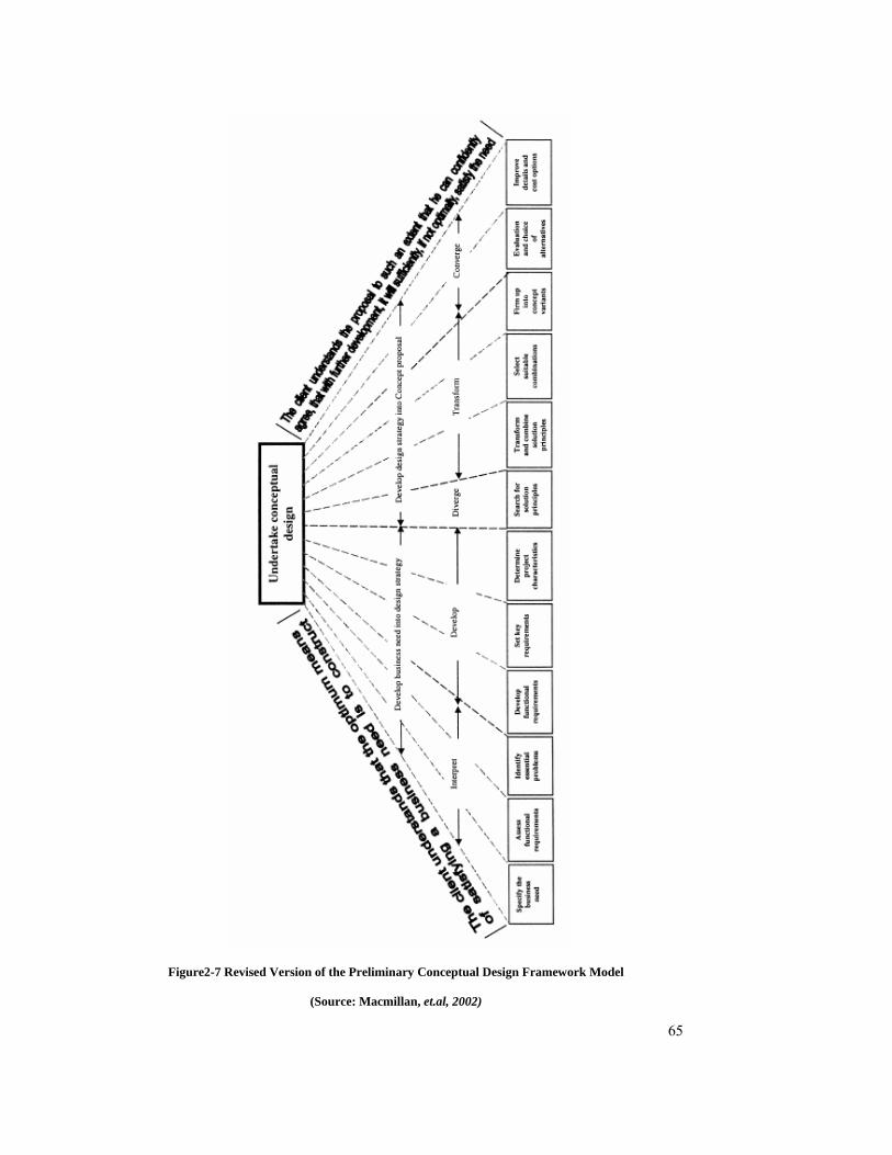
65
Figure2-7 Revised Version of the Preliminary Conceptual Design Framework Model
(Source: Macmillan, et.al, 2002)
66
2.5 SUMMARY
The early sections of this chapter identified the three phases of the building design process,
adopted from the RAIA Advisory Notes (RAIA, 2000) and RIBA Plan of Work (1999), as the
main focus for this research. These phase are: ‘schematic design stage’, ‘design development
stage’ and ‘documentation stage’. Additionally, for each design stage, a definition, purpose,
task to be done and people involved, as well as the relationships of designer with other
parties, were presented.
The second section reviewed the literature directly relevant to ICT and its implications during
the building design process. The findings were presented as a series of issues or “strands”,
which covered design communication, design information management, ICT, and the impact
and challenge of ICT developments for the building design process.
The process mapping methodology was explained and described, beginning with a brief
definition of process and process mapping, and concluding with the IDEF0 mapping
methodology as the focus of this research. Four process models of building design were
reviewed. These were: Generic Design and Construction Process Protocol (GDCPP), RIBA
Plan of Work, Analytical Design Planning Technique (ADePT), and Conceptual Design
Framework Model.
The next chapter will focus on the presentation of a model of the design process using IDEF0
functional modelling technique, and definitions of the research variables.

67
3 IDEF0 MODEL DEVELOPMENT
3.1 INTRODUCTION
“Processes are about changes of state. A process model is thus a description of a development
or a course of events. The process model contains the verbs that we think are characteristic of
the process. But giving verbs visual representations is not as easy and intuitively achieved as
is the case for nouns…The modelling method is, in many cases, a filter between what is
desired to express and what is possible to express.”
(Linde, 2001)
This chapter will discuss the different types of model, the development of the building design
process model, how the process can be mapped, and how the IDEF0 process mapping
software is adapted. The model presented in this chapter is an improvement and expansion of
a high level GDCPP Process Protocol Map developed by the University of Salford in
conjunction with the industrial partners to the GDCPP and Process Protocol Level II Project
(GDCPP, 1996). The original model was designed to support and encourage integration and
proper co-ordination between the various participants or stakeholders of a construction project
(Aouad et al., 1998b).
The Advisory notes published by The Royal Australia Institute of Architects (RAIA),
‘AN10.01.100-Guide Note’ (RAIA, 2000) and ‘AN10.01.101-Practice note’ (RAIA, 1993) as
well as The RIBA Outline Plan of Work (1998) were also adopted as a guide for developing
the lower level activities during the building design process.
3.2 MODEL CLASSIFICATION
According to NAAIDT (1995), “… a model is a representation of reality constructed to
explore particular aspects or properties. It is usually a simplification of reality but in the case
of a full-size prototype, even though virtually all aspects are modelled they can still only
represent reality since the object did not exist before this stage! It is also likely that a second
version of any of these first prototypes would be modified as a result of the evaluation, or field
testing, or the model and any production version would probably use alternative materials
and processes.”

68
Models can be classified into many categories based on different schemes. Hazelrigg (1996)
pointed out that there are predictive models and descriptive models. A predictive model is a
model that predicts or forecasts a future trend of a system or behaviour. SearchCRM.com
(http://searchcrm.techtarget.com) defines predictive modelling as “… a process used in
predictive analytics to create a statistical model or future behaviour…it is made up of a
number of predictors, variable factors that are likely to influence future behaviours or
results”. On the other hand, a descriptive model describes a process and how it will behave
(Rangel, 1999). One fundamental difference that must be understood between predictive
models and descriptive models is that "… descriptive models can be and often are precisely
correct; predictive models are rarely precisely correct" (Hazilrigg, 1996).
A second scheme of categorizing models is supported by Rangel (1999), NAAIDT (1995),
and Raftery (1998). They consider that there are three types of model: iconic, analogue and
symbolic. Raftery (1998) brought out a further type, the conceptual model. They are described
as follows:
• Iconic models – are scaled transformations of the actual physical system. A good
example is a scaled architectural model of a building where only the identical
shape, colour and layout are presented in the model. This may be used principally
to communicate design ideas between designers, engineers and to clients. For
example, sketches, 3D prototypes, MS paint, animation, photograph may be used to
represent reality.
• Analogue models – “… explore particular features of an idea by stripping away
detail and focusing, via a suitable analogous representation, on just a few key
elements” (NAAIDT, 1995). An example of an analogue model in building
economics is the cash flow curve where the project elapsed time is represented by a
distance along a horizontal line, and the cumulative expenditure of the project is
represented by a distance along a vertical line (Raftery, 1998).
• Symbolic models – “… are mathematical representations of the phenomenon under
scrutiny” (Raftery, 1998). Symbolic models are an abstraction of reality that is very
useful at analysing performance and predicting events. Common examples include
mathematical models to represents: population growth and heat flow.
• Conceptual models – Raftery (1998) described these as “… conceptual models
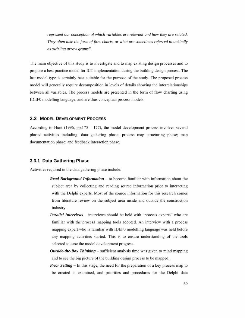
69
represent our conception of which variables are relevant and how they are related.
They often take the form of flow charts, or what are sometimes referred to unkindly
as swirling arrow grams”.
The main objective of this study is to investigate and to map existing design processes and to
propose a best practice model for ICT implementation during the building design process. The
last model type is certainly best suitable for the purpose of the study. The proposed process
model will generally require decomposition in levels of details showing the interrelationships
between all variables. The process models are presented in the form of flow charting using
IDEF0 modelling language, and are thus conceptual process models.
3.3 MODEL DEVELOPMENT PROCESS
According to Hunt (1996, pp.175 – 177), the model development process involves several
phased activities including: data gathering phase; process map structuring phase; map
documentation phase; and feedback interaction phase.
3.3.1 Data Gathering Phase
Activities required in the data gathering phase include:
Read Background Information – to become familiar with information about the
subject area by collecting and reading source information prior to interacting
with the Delphi experts. Most of the source information for this research comes
from literature review on the subject area inside and outside the construction
industry.
Parallel Interviews – interviews should be held with “process experts” who are
familiar with the process mapping tools adopted. An interview with a process
mapping expert who is familiar with IDEF0 modelling language was held before
any mapping activities started. This is to ensure understanding of the tools
selected to ease the model development progress.
Outside-the-Box Thinking – sufficient analysis time was given to mind mapping
and to see the big picture of the building design process to be mapped.
Prior Setting – In this stage, the need for the preparation of a key process map to
be created is examined, and priorities and procedures for the Delphi data
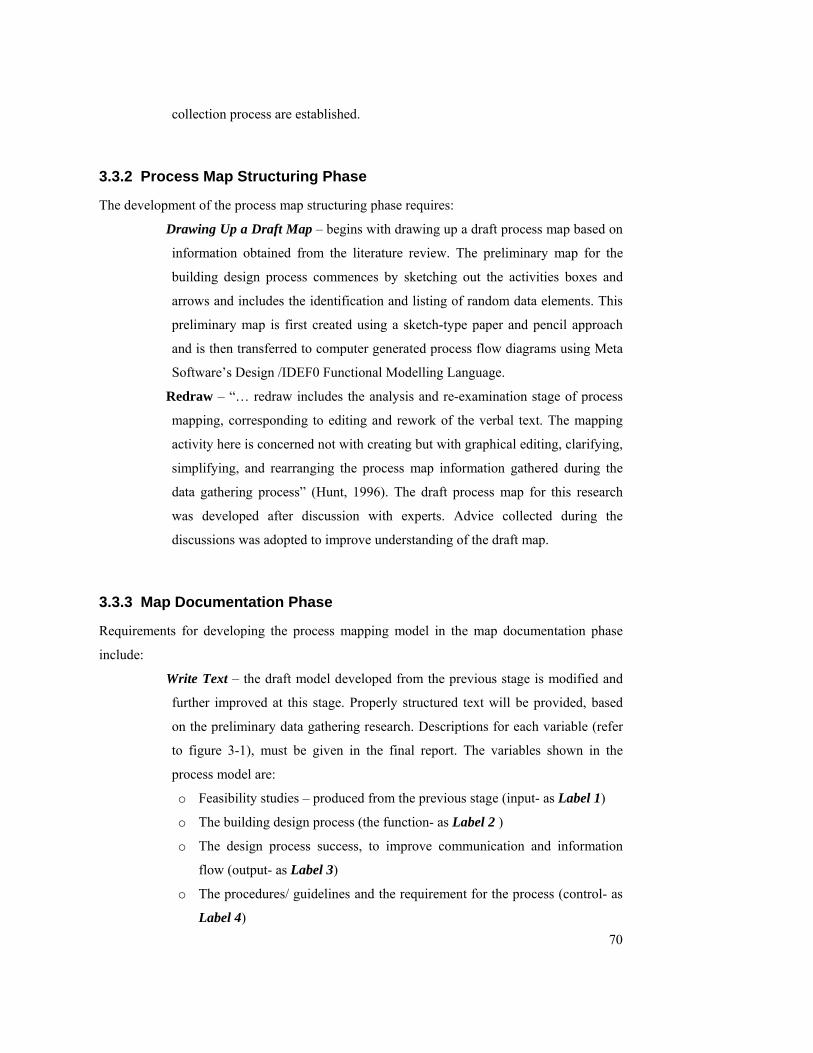
70
collection process are established.
3.3.2 Process Map Structuring Phase
The development of the process map structuring phase requires:
Drawing Up a Draft Map – begins with drawing up a draft process map based on
information obtained from the literature review. The preliminary map for the
building design process commences by sketching out the activities boxes and
arrows and includes the identification and listing of random data elements. This
preliminary map is first created using a sketch-type paper and pencil approach
and is then transferred to computer generated process flow diagrams using Meta
Software’s Design /IDEF0 Functional Modelling Language.
Redraw – “… redraw includes the analysis and re-examination stage of process
mapping, corresponding to editing and rework of the verbal text. The mapping
activity here is concerned not with creating but with graphical editing, clarifying,
simplifying, and rearranging the process map information gathered during the
data gathering process” (Hunt, 1996). The draft process map for this research
was developed after discussion with experts. Advice collected during the
discussions was adopted to improve understanding of the draft map.
3.3.3 Map Documentation Phase
Requirements for developing the process mapping model in the map documentation phase
include:
Write Text – the draft model developed from the previous stage is modified and
further improved at this stage. Properly structured text will be provided, based
on the preliminary data gathering research. Descriptions for each variable (refer
to figure 3-1), must be given in the final report. The variables shown in the
process model are:
o Feasibility studies – produced from the previous stage (input- as Label 1)
o The building design process (the function- as Label 2 )
o The design process success, to improve communication and information
flow (output- as Label 3)
o The procedures/ guidelines and the requirement for the process (control- as
Label 4)
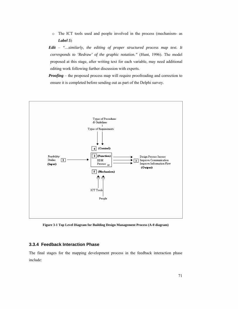
71
o The ICT tools used and people involved in the process (mechanism- as
Label 5)
Edit – “…similarly, the editing of proper structured process map text. It
corresponds to ‘Redraw’ of the graphic notation.” (Hunt, 1996). The model
proposed at this stage, after writing text for each variable, may need additional
editing work following further discussion with experts.
Proofing – the proposed process map will require proofreading and correction to
ensure it is completed before sending out as part of the Delphi survey.
Figure 3-1 Top Level Diagram for Building Design Management Process (A-0 diagram)
3.3.4 Feedback Interaction Phase
The final stages for the mapping development process in the feedback interaction phase
include:

72
Read It – the draft preliminary process map will be sent out for review and
comment among the Delphi experts.
Reaction – this refers to the researcher’s reaction to the experts’ comments
returned during the Delphi rounds. Changes and modifications to the preliminary
process map may be required.
Group Meetings – “… this is all the time spent in group meetings reviewing
progress or brainstorming the next steps in developing the process map.” (Hunt,
1996). After each round of the Delphi process, feedback from Delphi experts
will be analysed to plan the further development of the process map. This
process is repeated until a consensus is achieved in Delphi rounds.
3.4 THE PROPOSED MODEL
The top level diagram of the proposed model is presented in Figure 3-1. As mentioned earlier,
IDEF0 modelling language, a process modelling technique based on a well established
Structured Analysis and Design Technique (SADT) is adopted.
3.4.1 Assumptions to the model
In developing the model, certain assumptions are made:
The activity schedule based on a ‘fully designed commercial building project’ also
refers to the traditional ‘design-bid-construct project’ approach to building
procurement, and may vary for alternative procurement methods.
Advisory notes published by The Royal Australia Institute of Architects (RAIA),
‘AN10.01.100-Guide Note’ (RAIA, 2000) and ‘AN10.01.101-Practice note’ (RAIA,
1993) were adopted as the guide for developing the lower level activities during the
building design process.
The RIBA Outline Plan of Work (1998) was adopted as a reference for developing the
lower level activities during the building design process.
‘ICT tools’ and ‘people’ which act as mechanisms are not mapped in this process
model.
Figure 3-1 describes the interrelationship between variables represented using IDEF0
modelling language. The next section describes each of the research variables in a more

73
detailed way.
3.4.2 Model Interpretation
The detailed process model for the building design process is presented in Appendix-A. The
following describes the interpretation of the process model:
The process model is presented in hierarchical (top down) format;
The model should be read from left to right;
Interpretation of the model should normally go from ‘output’ from one activity to
‘input’ of another activity, however, the ‘output’ of one activity can sometimes act as
‘control’ to another activity in the process map.
Figure 2-3 represents the context diagram of the process map. The activities numbers
represent each unique building design activity and should be interpreted as: A0 as the
top level, A4 as the second level, A45 as the third level, and A452 as the lower level in
the process map (see chapter 2.4.3).
3.5 DEFINITION OF RESEARCH VARIABLES
Figure 3-1 presents the top level context diagram which sets the model scope and boundary
for the research. This section defines the model’s variables and their relationship to each
other. While the process map will be mapped using IDEF0 language, each activity is assigned
an identification code (e.g. A1, A11, and A111…), as it gets into greater and greater levels of
detail through decomposition.
3.5.1 Feasibility Studies Stage (as Input)
At the Feasibilities Studies Stage, a study of user requirements, site conditions, planning,
design, and cost parameters is carried out to provide the client with an appraisal and
recommendation in order that the client may determine the form in which the project is to
proceed, ensuring that it is feasible, functionally, technically and financially (RIBA, 1980).
The feasibility study stage (for a commercial investment project) also explores the financial
feasibility (financial performance) of the project, on a return-to-investment basis for the client
over the investment period, using projections of the estimated rental incomes and operating

74
costs. This financial modelling process informs the subsequent design process.
The following design information and decisions are obtained at the end of this stage and are
used as an input for the next stage which is the Outline Design Stage.
“Additional information on the client’s requirements to that provided at the
inception stage (stage before feasibility);
Detailed information on the site;
Information from third parties who may be involved with the proposed building;
Predictive information on costs”
(Thompson, 1999)
3.5.2 Building Design Process (as Function)
The model focuses on the pre-tender stages of the building design process. In the Architect
Agreement [Long Form], Scope of Services, RAIA Advisory Note (AN10.01.100) (RAIA,
2000) the three main stages of the design process refer to:
Schematic Design
Design Development
Documentation
Each of these design stages is broken down into different sub-stages with a series of activities
for each sub-stage. Accomplishment of these activities may require the involvement of more
than one member of the design team and sometimes produces more than one product. As a
result, various tools are introduced as aids to help team members perform their roles in each
activity. Figure 3-2 shows the three main design stages that are the focus of this research..
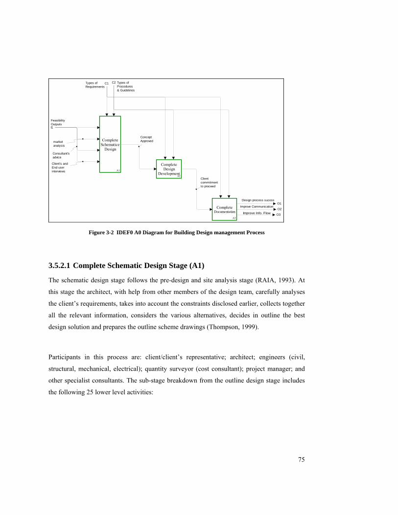
75
Complete Schematice
Design
A1
Complete Design
DevelopmentA2
Complete Documentation
A3
I1
FeasibilityOutputs
O2Improve Communication
Concept Approved
Client commitmentto proceed
C1Types of Requirements
C2 Types of Procedures & Guidelines
O1Design process sucess
O3Improve Info. Flow
market analysis
Consultant's advice
Client's and End user interviews
Figure 3-2 IDEF0 A0 Diagram for Building Design management Process
3.5.2.1 Complete Schematic Design Stage (A1)
The schematic design stage follows the pre-design and site analysis stage (RAIA, 1993). At
this stage the architect, with help from other members of the design team, carefully analyses
the client’s requirements, takes into account the constraints disclosed earlier, collects together
all the relevant information, considers the various alternatives, decides in outline the best
design solution and prepares the outline scheme drawings (Thompson, 1999).
Participants in this process are: client/client’s representative; architect; engineers (civil,
structural, mechanical, electrical); quantity surveyor (cost consultant); project manager; and
other specialist consultants. The sub-stage breakdown from the outline design stage includes
the following 25 lower level activities:

76
A11 – Develop and Define Design Requirements
This stage involves the following activities:
Liaise with Authorities (A111) – This activity involves consultation with relevant
local, regional, state and federal authorities to confirm all planning regulations. These
include: car parking requirements; height restrictions, density requirements, and
zoning requirements.
Site Analysis (A112) – site context analysis involves the preparation of a master plan
for overall development and phasing to show its best utilisation.
Conduct Outline Feasibility Design (A113) – this stage requires the involvement of
various members of the design team:
o Architect design services consist of preparing conceptual site and building
plans; preliminary sections and elevations; development of approximate
dimensions, areas and volumes.
o Initial involvement of various engineers for theirs professional
recommendations including, earthworks design, structural design, mechanical
design, hydraulic service design, electrical design, civil design, and landscape
design.
Assessment of Consultants’ recommendations (A114) – to gather, analyse and assess
the recommendations from consultants.
Conduct environmental analysis (A115) – to consider the environmental strengths
and weaknesses of the proposed development, and scan the environment for
opportunities on the selected site;
Seek client’s initial feedback (A116) – presentation to the Client to review
recommendations from previous stages for feedback.
A12- Estimate Resale Value
This stage is only applicable to private commercial projects and involves the following
activities:
Identify potential resale target/buyer (A121) – to identify potential buyers and to find
out the target group;
Assessment of resale value (A122) – to assess the resale value of the building (final
product), and may involve market analysis;
77
A13- Conduct Value Management Process
“Value management has been defined as a proactive, creative, problem solving service that
involves the use of a structured, facilitated, multi-disciplinary team approach to make explicit
the client’s value system using function analysis to expose the relationship between time, cost
and quality” (Kelly et al., 2004, pp. 77). According to Kelly et al. (2004), conducting a value
management workshop during outline design stage involves the following activities:
Review concept brief (A131) – to review concept brief obtained from previous stages
and to confirm the client’s objectives for the project. This review may cover: the initial
plans, elevations, sections, specification and cost plan of the proposed facility. It is
important to fully understand the concept brief, particularly the functional space
requirements and adjacency prior to the allocation of costs for each element of the
project.
Allocate costs (A132) – this stage involves the allocation of costs from the cost plan to
functions and spaces.
Highlight mismatches and risks (A133) – to identify and to highlight any mismatches
between cost allocation to functions and spaces. To run risk assessment for each
design option.
Evaluation and development of alternative solutions (A134) – evaluation of design
alternative and brainstorming for better solutions.
Presentations (A135) – presentations of preferred solution to the client or client’s
representative.
A14- Preparation of Outline Proposal
Prepare Outline proposal stage involves the following activities:
Ensure outline plan fulfils project brief (A141) – to ensure that the outline design
drawings encompass the requirements of the client brief.
Prepare design proposal (A142) – produce sketch drawings based on the information
obtained from various stakeholders including engineers, cost consultant, authorities
and other consultants.
Review authorities’ requirements (A143) – to review authorities’ requirements to
ensure that the outline schematic design meets all regulatory requirements.

78
Liaise with cost planning consultant (A144) – liaise with cost planning consultant to
prepare preliminary costing for the project, for comparison with target budgets.
Assess client’s initial feedback (A145) – Assess client’s initial feedback from stage
A116.
Initial Planning Permit Application Preparation (A146) – prepare initial scheme
design drawings, based on authorities’ comments, consultants’ recommendations and
client’s feedback.
A15- Prepare Preliminary Estimate
The following activities are involved:
Development of Probable Cost and Program (OPC) (A151) – liaison with cost
consultant to develop: probable construction cost range for the project.
Engineering cost studies/ liaise with engineers (A152) – undertake cost studies to
determine appropriate engineering solutions.
Search for principal solutions (A153) – assess and decide upon appropriate
design/cost solutions for the principal elements of the project.
Select suitable design/cost solution combination (A154) – assemble and choose the
most appropriate combinations of design/cost solutions.
Evaluation of alternatives (A155) – prepare costings to an appropriate level of detail,
and compare with budget targets.
Improve details and cost options (A156) – improve the details and cost options within
the alternative design solutions considered; update costing and budget comparisons;
report to client for decision-making.
3.5.2.2 Complete Design Development Stage (A2)
At this stage the design team should have a clear idea of the brief from the previous stage in
order to prepare a sufficiently detailed scheme design to show the spatial arrangement of the
various parts of the proposed building, as well as its appearance and an indication of the
materials to be used (Thompson, 1999). Team members have to work together and co-
ordinate their design outcomes.

79
Gray and Hughes (2001) emphasise that the completion of the design development process is
a crucial client decision point in a project as well as a key point in the management of the
process. They further point out that the client and the designer must agree on the complete
scope of the work.
More participants are involved in this stage of the design process. In addition to the design
team constituted for the earlier stages, statutory and other authorities will be involved,
together with other specialists such as landscape architects, interior designers, acoustic,
illumination, communication and security consultants. The sub-stage breakdown of the
Design Development Stage includes the following 15 lower level activities.
A21- Prepare Sketch Design Documentation
This stage involves the following activities:
Develop expansion of architecture design drawings (A211) – the development and
expansion of architectural schematic design documents, revised in accordance with
client’s instructions and as necessitated by any revision to cost estimates, including:
plans at each level, elevations, sections and other details or schedules sufficient to
fully explain the design (RAIA, 1993).
Prepare preliminary engineering design (A212) – consists of the continued
development of the various engineering designs as done in the outline feasibility
design stage A113.
Coordinate/liaise with all consultants (A213) – coordinate and integrate the design
work with all consultants.
Make required design changes (A214) – make required changes based on consultants’
recommendations.
Presentation of the schematic design (A215) – presentation of the schematic design to
all relevant stakeholders, such as: client, building owner, staff committee, user groups,
boards of directors, financiers, and owner’s consultants for comment (RAIA, 1993).
Design Visualisation – Model Construction (A216) – model construction (if
necessary); physical and/or virtual models of the proposed building, showing the
interrelationship of the spatial layouts, in 2D and 3D formats, are very useful for many
clients; they are also an effective way of depicting constructional methods.
80
A22- Run Design Evaluation Session
This stage involves the following activities:
Integrate preliminary consultants’ advice in design (A221) – all design team
members work together to make final decisions regarding design aspects, materials,
finishes, services, and various other matters.
Review authorities/council requirements (A222) – review all relevant planning and
authorities’ requirements eg. area calculations and car parking (RAIA, 2000).
Gather feedback from all authorities and consultants (A223) – feedback from all
authorities and consultant is consolidated into necessary design change proposals.
Finalised design documents (A224) – finalise and make required design changes
based on authorities’/consultants’ feedback.
Apply for planning permit (A225) – lodgement of documents by the architect on
behalf of the client to the relevant authorities for planning approval (RAIA, 1993).
A23- Prepare Sketch Design Cost Plan
Prepare Sketch Design Cost Plan Stage involves the following activities:
Estimating building cost (A231) – cost consultant prepares more detailed cost plan for
the project, based upon development of outline design, for comparison with target cost
budgets.
Prepare alternative estimates (A232) – for different construction methods, materials,
engineering systems to ensure that best design solutions are obtained within the
established budget.
Prepare program budget (A233) – show how the total cost is allocated among the
various parts of the project.
Prepare time schedule & organization plan (A234) – prepare outline time schedule
and organization plan to give the client an indication as to when building work will
commence on site and how long it will take to complete, together with a hierarchical
diagram of stakeholders based upon contractual/ communication/ authority structures.

81
3.5.2.3 Complete Documentation Stage (A3)
The complete documentation stage for the proposed building will commence upon
confirmation of approval of the planning permit. The design brief should not be modified after
this point in the design process as any changes may require reapplication of the planning
permit and result in inevitable delay in the commencement of building work on site. The
main objectives of this stage are: to obtain the necessary building permit; to obtain
rationalization and integration of sub-systems; to consider Occupational Health and Safety
requirements for the design (RAIA, 2005); and to provide scoping information to appoint
specialist trade contractors (Gray and Hughes, 2001).
“The National Occupational Health and Safety Commission (NOHSC), in association with
state bodies and other relevant stakeholders, has developed a draft national framework for
OHS improvement, including the concept of ‘safe design’, which encourages the adoption of
systematic approaches by government and industry” (RAIA, 2005). Again, as stated in the
“Occupational Health and Safety: safe design guide” (RAIA, 2005), “… safe design
encompasses all aspects of building design to ensure that a building can be safety built, used,
maintained, and demolished by those who construct and use it.”
During this stage, the building design is developed in a more finished form, including more
detailed drawings and specifications and incorporating the specialist contributions of the
various consultants (Thompson, 1999). Full design of every part of the building must be
produced at the end of this stage.
Depending upon the procurement system used for the project, the building contractor may
become part of the design team at this point. The sub-stage breakdown for the Detail Design
Stage includes the following 14 lower level activities.
A31- Conduct Detail Design Management
The Conduct Detail Design Management stage involves the following activities:
Prepare detailed architectural drawings (A311) – develop the scheme design
drawings in a more finished form, including more detailed drawings and specifications
82
and incorporating the specialist contributions of the various consultants. The
documents include:
o Working drawings for tendering and construction.
o Specifications comprising detailed written descriptions of the project materials
and workmanship standards required.
Develop detail engineering design (A312) – develop engineering documentation,
setting forth in detail the various engineering construction requirements of the project
for tendering and construction purposes, consisting of the preparation of final
engineering calculations; drawings; specifications and schedules.
Coordinate/liaise with all consultants (A313) – coordinate and integrate sub-
consultant design with the architectural drawings and specifications (RAIA, 2000).
Presentation to authority/council (A314) – final presentation to local
authority/council before lodgement to ensure design complies with all building
regulations.
Preparations of documents for building permit application (A315) – prepare
documentation including dimensioned plans, sections and elevations to adequately
describe the design for the purpose of obtaining approval to construct (RAIA, 2000).
A32- Conduct Cost Checking
This stage involves the following activities:
Analysis & evaluate design alternatives (A321) – interaction between all project
professionals and facility manager (if appointed) to ensure that the building provides
its users with basic elements that maintain the necessary comfort which allows them to
carry out their jobs.
Investigate design cost efficiency (A322) – ensure cost efficiency of the proposed
building design, consider and identify which elements of the building require the least
maintenance, and incur the fewest breakdowns and repairs and also those with the
most maintenance and repair requirements.
Identify and analyse life cycle cost (A323) – assess the life cycle cost of the building
(short-term; medium-term; and long-term).
Review optimization of energy performance (A324) – review energy performance for
the proposed design, to consider which elements within the building are the most
energy inefficient.

83
Conduct design cost check (A325) – cost consultant to review the cost plan after all
stages and to carry out cost studies and cost checks as the design reaches finalisation.
A33- Audit Completion of Detail Plan
Audit Completion of Detail Plan involves the following activities:
Lodgement for building permit (A331) – submit application to the relevant authority
for building permit approval.
Rationalise & integrate sub-systems designs (A332) – rationalize and integrate all
design sub-systems to make sure there are no conflicts.
Consider Occupational Health and Safety- Safe Design (A333) – ensure that the
proposed design can be safely built, used, maintained, and demolished by those who
construct and use it (RAIA, 2005).
Conduct risk management (A334) – assess and balance the contingencies of risk with
their specific contractual, financial, operational and organizational requirements by
transferring through the combination of insurance, risk financing, and contract
indemnification provisions.
3.5.3 Design process success (as Output)
Design process success is achieved when all requirements specified are met - time and within
budget - with no remaining conflicts between project team members; and client’s satisfaction
is achieved.
3.5.4 Improve communication (as Output)
One of the main benefits proposed for ICT tools in the building design process is that they
enable more natural forms of communication through ICT application (BT, 1995). For
example, videoconferencing can replace a face to face meeting, where it can take place at any
time with less effort. In this research study, communication is said to be improved when the
any of following are achieved:
Time required to respond to queries is reduced;
Cost savings can be achieved on travelling, overheads, communication;
Decision making can be done faster;
84
Communication quality is improved.
3.5.5 Improve quality of Information Flow (as Output)
A key to successful sharing of industry information is the ability to structure and arrange
information so that it can be accessed easily (BT, 1995, pp.22). The quality of information
flow among project participants is determined from the following:
“Improve documentation quality;
Decrease design errors and requests for information;
Save time and save cost;
Reduce response time to answer queries”
(Weippert et al., 2003)
3.5.6 Types of Procedures and Guidelines (as Control)
The procedures and guidelines to be taken into account during the building design process
are:
Cost and time guide – usually set by the client at the very beginning of the inception
or feasibility stage and used as a guideline for later decision making.
Legal & statutory procedures – according to RIBA (1980, pp.407-408), as soon as
possible after being commissioned for a project, the designer should confirm with
his/her client and the client’s legal adviser a range of matters which may affect
development of the project; to find out which authorities are concerned with which
functions, the nature and form of applications which are required, and to whom they
should be addressed.
Value management checklists – produced during the value engineering process and
used for exploration of alternative solutions.
Building cost guide – published and updated frequently; used during the design
process as a guideline for estimating the cost of each component.
Cost planning – prepared by appointed consultant. As the cost of any project is
significant, particularly to the client, cost estimation and cost planning are expected at
frequent and regular stages of the design process.
Cost allocation guide – similar to the cost guide, this may be prepared by the cost
consultant to show the approximate cost allocation to each element or component.

85
Design specification – produced by each designer stating the detail of the design to
simplify the cost estimating process; it may also be used as a guideline by the cost
consultant while preparing tender bills of quantities.
Engineering design guide – engineering design begins towards the end of the outline
design process. Used by specialist engineers as a reference while preparing
engineering drawings.
Summary report – a summary report is produced after the detail scheme design stage
and used as a guideline in later stages of the design process as it provides detailed
design information on what has been achieved at the earlier stage.
Occupational Health & Safety – Safe Design Guide (RAIA, 2005) – to be used as a
guideline/procedure while preparing design to ensure safe design of “workplaces”.
3.5.7 Types of Requirements (as Control)
During the building design process, many requirements have to be considered. The types of
requirement that are included in the research model are categorized as: client’s requirements;
business requirements; market requirements, user requirements; site requirements; statutory
requirements and authority and planning requirements. All project team members (including
designer, specialist contractor, project manager, etc.) must ensure that the final product meets
all these requirements.
3.5.8 ICT Tools (as Mechanism)
Various ICT tools are used by project team members during the building design process to
provide a more effective and efficient output. In this study, ICT tools are categorised into:
ICT infrastructure; ICT for information management; and ICT for communication. Details for
each of these categories were explained in Chapter 2.
3.5.9 People (as Mechanism)
As mentioned in Chapter 2, the building design process involves multi-disciplinary
professionals working together to achieve a common purpose. The individual people will not
be mapped in the IDEF0 building design process mapping model, but they will be briefly
discussed here due to their interrelationship with each other and their particular needs for ICT

86
tools. According to the RAIA Advisory Note (RAIA, 1994) and RIBA hand book (1980, pp
54-67), the allied professionals involved during the building design process and their
functions comprise:
The architect – based on his/her level of training and according to qualification and
experience, may carry out:
- land and building site survey;
- technical studies in feasibility;
- preparation design drawings and illustrations;
- model making of simple kind;
- production drawings, specification and schedules;
- special technical investigations;
- liaison with specialists and consultants’ staff;
- programmed checking of resources, costs, information;
- administrative support, e.g. statutory controls, contract administration, specialist
quotations; and
- assist site inspection.
The quantity surveyor/cost consultant – is trained and qualified to advise designers
on matters relating to cost and contracts in building, civil engineering, and mechanical
and electrical engineering projects. The normal service of a cost consultant includes:
- provision of cost advice;
- cost checking of the detail design and production drawings against the agreed
cost plan; and
- provision on advice on tendering procedures and contractual arrangements.
- preparation of tender bills of quantities where required.
The structural engineer – advises on:
- soil and climatic conditions, wind loads and temperature limits;
- natural drainage and traffic considerations;
- the stability of the building at as low a cost as possible;
- the form of structure which will fulfil the many functions required (including the
ground loads and stresses which will result from the design); and
- expansion and contraction treatment for the structure.
The services engineer – is concerned with:
- the provisions for control of the internal environment by means of heating,
ventilating, air-conditioning and lighting installations, and;
87
- the provision of utilities, such as electrical supplies, lifts, compressed air;
- the inclusion of hydraulic services and drainage.
The landscape architect – is concerned with:
- the open space around the building;
The local authorities/council/ building surveyor – represents local authorities as an
officer of central or local government or the building survey (note: this function has
been privatised under many jurisdictions. Private building surveyors certify the
compliance of the project with planning law and building regulations) may be
concerned with providing information on:
- transport and communications, retailing, employment, economic growth or
decline, social and demographic facilities, resource management, pollution,
ecology or recreation and leisure;
- control over land use, preservation orders for trees and buildings,
advertisements, overhead lines and underground pipes, natural resources and
land compensation.
The acoustic consultant – these services are concerned with:
- precise acoustical measurement of all environmental noise leading to initial
acoustical technical schemes and feasibility studies;
- predicting acceptability levels resulting from environmental noise-climate
measurements for determination of acoustic design parameters in structures,
architectural, building acoustics and engineering acoustics.
Other designers who may be involved during the building design process include:
- interior designer;
- illumination specialists;
- security specialist;
- property agencies;
- financial specialists.
3.6 SUMMARY
In this chapter, a model of the building design process was developed for a large commercial
building project. Conceptual models were considered as the most suitable type of model for
the research.
88
The model development process is described. This involves several phased activities
including: data gathering phase; process map structuring phase; map documentation phase;
and feedback interaction phase.
The final section of this chapter focused on the proposed IDEF0 model for the building design
process. Research variables were defined and assumptions were made to the model. A total of
54 activities were derived from the three main design stages: schematic design stage; design
development stage; and documentation stage. Other research variables identified include:
feasibility studies stage (as input); building design process (as function); design process
success (as output); improve communication (as output); improve quality of information flow
(as output); types of procedure and guideline (as control); types of requirements (as control);
ICT tools (as mechanism); and people (as mechanism).
The next chapter focuses on the research methodology and design, looking at the design and
administration of the DELPHI survey and data analysis procedures.

89
4 RESEARCH METHODOLOGY & DESIGN
4.1 INTRODUCTION
A staged approach has been adopted for the purpose of this research. Stage one was the
literature review. Related literature was reviewed so as to give deep knowledge on the
research topic. The literature was sourced mainly from conference and journal papers, books,
academic theses and dissertations and Internet resources.
Understanding derived from the literature review assisted in clarifying relevant issues and in
model development. Delphi technique was adopted to test and verify the proposed model.
Five “strands” for the research were identified and discussed in the literature review (Chapter
2). The issues mainly focus on: the existing information management and communication
during the building design process; to what extent design professionals adopt ICT in their
daily routine; the impact of technology; the barriers to the implementation of technology;
existing communication problems faced by design team member during the building design
process; and the techniques and tools used during the building design process.
Process model development comprised the second step for the research process. IDEF0
process mapping was chosen to map the building design process for traditional contract
procurement project (design-bid-construct) for a large scale commercial investment building
project. For this research, the building design process is confined to the pre-construction
stages as stated in Architect Agreement [Long Form], Scope of Services, RAIA Advisory
Note (RAIA, 2000) as: schematic design stage, design development stage and the
documentation stage. People are not mapped into the conceptual IDEF0 process map,
however, they are mapped in the ‘ICT implementation maps’ at a later stage of the research.
In stage three of the research, the process model is validated and tested by experts through
Delphi survey.
Four rounds of Delphi surveys were conducted between November 2004 and April 2005. The
data collected from all Delphi rounds are presented and analysed in Chapter 5.

90
Data collected from four rounds Delphi survey were adapted in proposing an “ICT
Implementation Map during the Building Design Process” (current and in five years time) in
stage five of the study (presented in Chapter 6). The proposed ICT Implementation Map was
be tested and further improved through interviews with three experts during November 2005.
The modified copies of ‘ICT implementation maps’ and the analysis of result from interview
are presented in the discussion in Chapter 7.
Conclusions and recommendation for future research are presented in the final chapter
(Chapter 8) of this thesis.
This chapter justifies the research methodology selected, and describes the technique used to
gather the primary data necessary for the development of the ‘ICT implementation maps for
the building design processes’.
4.2 RESEARCH DESIGN JUSTIFICATION
Choosing an appropriate research approach is essential to research success. Selection of an
appropriate research approach may be based on the natural perspective of the research and the
research questions to be answered. One of the main components of this study is the
development and testing of ICT implementation maps for the building design process, where
participants are encouraged to offer comment on all the issues under review and to propose
new ideas. Interaction between the participants and the researcher may be necessary during
the data collection process. As a result of the expense and time commitments necessary to
bring together all participants to explore these issues and the fact that exploration of these
issues do not lend themselves to the use of statistical, analytical techniques, Cabaniss (2001)
suggests that the Delphi method is the most appropriate means of collecting data for this type
of research.
Kennedy (2002, pp.112) argues that: “… one of the key advantages of Delphi methodology
lies in its use of qualitative technique to draw on collective expert judgement in a format that
allows for a subsequent quantitative analysis of these data… the methodology is systematic
and uniform and can be used to collect data from individuals who are widely separated
geographically.” While one of the key issues for this study aims to explore the usage level of
91
ICT during building design process, some quantitative data are expected. This further
enhances the decision to adopt Delphi technique for data collection as best suiting the purpose
of this study.
4.3 DESIGN AND ADMINISTRATION OF THE DELPHI SURVEY
“Delphi may be characterised as a method for structuring a group communication process so
that the process is effective in allowing a group of individuals, as a whole, to deal with a
complex problem.”
(Linstone and Turoff, 1975)
“Delphi is an attempt to elicit expert opinion in a systematic manner for useful results. It
usually involves iterative questionnaires administered to individual experts in a manner
protecting the anonymity of their responses. Feedback of the results accompanies each
iteration of the questionnaire, which continues until convergence of opinion, or a point of
diminishing returns is reached. The end product is the consensus of experts, including their
commentary, on each of the questionnaire items, usually organised as a written report by the
Delphi investigator.”
(Sackman, 1975)
Wedley (1980) points out that the RAND Corporation formulated the Delphi process in the
early 1950’s to enable geographically dispersed warfare experts to predict changes in military
technology. He further notes that their new concept was classified and kept a military secret
until the 1950’s.
‘Delphi’ was named after the site of the Greek oracle “where necromancers foretold the
future using hallucinogenic vapours and animal entrails” (Linstone and Turoff, 1975). They
state that the early uses of modern Delphi techniques were to carry out studies for the U.S. Air
Force to examine the potential effectiveness of automatic attack. The study involved a series
of questionnaires with controlled feedback to determine the opinion of a group of experts
about the U.S. industrial systems most likely to be offensively targeted by Soviet strategic
planers. At that time, the alternative would have been an extensive and costly data-collection
process, including programming and executing computer models that could not be handled by
available computers (Linstone and Turoff, 1975).
92
In 1975, two important books on the Delphi-method were published, one by Delbecq, Van de
Ven and Gustafson and the other by Lindstone and Turoff (cited by Costa, 2000). These
books primarily addressed theoretical and methodological issues regarding the technique. At
the same time, Sackman (1975) published a book called “Delphi Critique” to highlight some
of the negative aspects of the method.
Over the past 50 years a variety of Delphi techniques has been developed. In addition to
consensus building, Delphi techniques were developed for such uses as decision making,
needs assessment, identifying objectives, future forecasting and policy making (Ferris,
1998).Today, the Delphi technique is widely used by corporations, universities, government
agencies, and non-profit organizations for planning, technical and strategic evaluations as well
as forecasting in many areas (Ziglio, 1996).
The characteristics of Delphi compiled by Sackman (1975) are as follows:
“The format is typically, but not always, a paper and pencil questionnaire; it
may be administered by mail, in a personal interview, or at an interactive, online
computer console. The basic data-presentation and data-collection technique is
the structured, formal questionnaire in each case.
The questionnaire consists of a series of items using similar or different scales,
quantitative or qualitative, concerned with study objectives.
The director, participants, or both may generate the questionnaire items.
The questionnaire is accompanied by some set of instructions, guidelines, and
ground rules.
The questionnaire is administered to the participants for two or more rounds;
participants respond to scaled objective items; they may or may not respond to
open-ended verbal requests.
Each iteration is accompanied by some form of statistical feedback, which
usually involves a measure of central tendency, some measure of dispersion, or
perhaps the entire frequency distribution of responses for each item.
Each iteration may or may not be accompanied by selected verbal feedback
determined by the director.
Individual responses to items are kept anonymous for all iterations. However,
the director may list participants by name and affiliation as part of the study.
93
Outliers (upper and lower quartile responses) may be asked by the director to
provide written justification for their responses.
Iteration with the above types of feedback is continued until convergence of
opinion, or ‘consensus’, reaches some point of diminishing returns, as
determined by the director.
Participants do not meet or discuss issues face to face, and they may be
geographically remote from one another.”
The following sections provide a brief discussion on the Delphi process and the reasons
behind the adoption of Delphi technique.
4.3.1 The Delphi Process
Delphi is a systematic polling of opinions of a panel of experts knowledgeable on a given
topic through iterative administration of questionnaires - referred to as ‘rounds’ (Dalkey et al.,
1972). The experts are selected based on the areas of expertise required. They are presumably
people who have clear, systematised ideas about their special area of knowledge, and who can
reply in consistent and organised fashion. The experts are asked a series of questions about
the likelihood of certain events occurring. In most cases, the first questionnaire poses the
problem in broad terms and invites answers and comments. Responses to the first
questionnaire are then summarized and used to construct the second questionnaire, which
presents the results of the first and gives participants an opportunity to refine their responses,
clarify issues, identify areas of agreement or disagreement, and develop priorities.
Hostrop describes how Helmer, one of the developers of Delphi, envisioned the method (cited
by Costa, 2000, p.53-54):
“Participants (who usually remain anonymous) are asked to state their opinion
on a specific topic in the form of brief written responses to prepared
questionnaires, such as recommended activities or predictions for the future.
Participants are then asked to evaluate their responses against some criterion,
such as importance, and chance of success.
Next the statements made by the participants are received by the investigator.
94
Each participant then receives the refined list and a summary of responses to the
items and, if in the minority, is asked to revise his (or her) opinion or to indicate
reason(s) for remaining in the minority.
The statements made by the participants are again received by the investigator
who further clarifies, refines, and summarizes to the responses.
Each participant then receives the further refined topical list, which includes
both an updated summary of responses and a summary of minority opinions.
Each participant is also given a final chance to revise his (her) opinions.
Finally, this investigator receives the last round of questionnaires, which he
(she) then summarizes in a final report. The successive, individual and
independent process of re-questioning each of the experts, via the investigator, is
designed to eliminate misinterpretation of the question and the feedback, and to
bring to light knowledge available to one or a few members of the group, but not
all of them.”
Figure 4-1 presents a schematic illustration of the Delphi process.
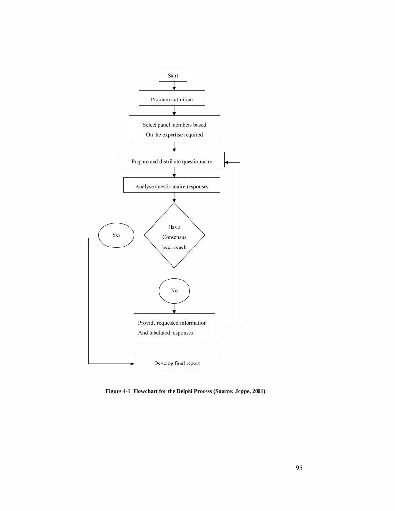
95
Figure 4-1 Flowchart for the Delphi Process (Source: Joppe, 2001)
Start
Problem definition
Select panel members based
On the expertise required
Prepare and distribute questionnaire
Analyse questionnaire responses
Has a
Consensus
been reach
Yes
No
Provide requested information
And tabulated responses
Develop final report

96
4.3.2 Evaluation of Delphi
As with all other research methods, the Delphi approach attracts support and criticism. One of
the major benefits of Delphi is the anonymity of participants. Hess and King (2002) state that
anonymity is often adopted to promote frank discussion, improve group response, and reduce
inhibitions among panellists. Some of the advantages (Williamson, 2002) are as follows:
“Delphi elicits responses from experts who bring knowledge, authority and insight
to the issues involved.
The systematic bringing together of expert views in several rounds to reach
consensus provides a stronger basis for decision than do individual judgments.
Experts can be gathered from all over the world and are not limited to a
geographic region.
The process also provides a cooperative learning exercise for the experts involved.
It allows respondents to modify their answers without the pressure of face-to-face
interaction. Thus the effect of strong personalities and people of higher status is
avoided.
It allows for the exploration and review of the assumptions, information or
opinions leading to different assessments.
Controlled feedback and anonymity help panellists to revise their views without
publicly admitting that they have done so. They are thus encouraged to take up a
more personal viewpoint rather than a cautious institutional position.
By giving respondents the chance to consider the answer and reasons of other
respondents and to modify their own answers, a consensus of opinion may emerge.
The degree of divergence of opinion, if any, and the reasons for it, can be gauged.
Experience has shown that in Delphi applications there is an increasing
convergence in the opinions of respondents from iteration to iteration. Where
accuracy of response can be checked, it seems to increase with iteration.
The process is relatively inexpensive to organize and administer.”
(Williamson, 2002)
Other advantages are such as:
“It is one of the few forecasting methods that have a fair to good prediction
accuracy over different time horizons – short-term, medium, and long range”
(Costa, 2000).
97
“Embraces the philosophy that the whole is greater than the sum of its part, which
will promote teamwork and group decision-making” (Costa, 2000).
“Motivates independent thought and gradual formation of group decision, which is
appropriate for open-ended problems” (Costa, 2000).
“Ability to explore, coolly and objectively, issues that required judgment” (Gordon,
1994).
“The technique eliminates open discussions and committee activity and thus
reduces the influence of psychological factors such as specious persuasion,
unwillingness to abandon publicly expressed opinions and the bandwagon effect of
majority opinion” (Sharma et al., 2003)
Among the disadvantages of Delphi method, the large amount of time required to conduct
several rounds for data collection is one of the issues that concerns researchers most. The
most extensive critique on Delphi approach is made by Sackman (1975) who criticizes the
method as being unscientific. His complaints against the Delphi method are in terms of the
concept of ‘expert’ as follows:
“The concept of expert is virtually meaningless in experiments dealing with
complex social phenomena.
Sole or primary reliance on expert opinion in the social sciences has long been
discredited and now has no serious advocates.
Anonymous panels chosen in unspecified ways increase the likelihood of
contaminated, elitist “expert” samples.
There exists an uncontrolled and unknown expert halo effect in Delphi
contributing to expert oversell.
Collective expert opinion directly reinforces unaccountability for Delphi results
for all concerned: the director, panellists, and users.
Experts and non-experts consistently give indistinguishable responses in
forecasting or evaluating social phenomena impacting on common values and
attitudes.
There is no explicit matching of skills required by Delphi questions against
objectively measurable skills of the panellists.”
(Sackman, 1975)

98
To deal with the criticisms on ‘experts’, the selection criteria for the panel experts were set
after discussion with the research supervisors and building professionals to ensure that well
experienced and qualified panel experts were recruited. However, as Philips (1990) (cited by
Kennedy, 2002, pp.111) comments: “… what is crucial to the objective of any inquiry –
whether is quantitative or qualitative – is the critical spirit in which it has been carried out”.
4.3.3 Objective of Delphi for this study
The primary objective of this Delphi study is to test and verify a proposed building design
process mapping model using IDEF0 functional modelling language. The proposed model is
intended to map all activities involved during the building design process, taking into account
the requirements, procedures and guidelines that affect the process as well as the outcomes of
the process, together with the aid of ICT tools.
The model is based on the preconstruction stages of the building design process set out in the
RAIA Advisory Notes (AN10.01.100) and RIBA Plan of Work (1998). It provides a clear
picture of how one activity is related to another during the building design process.
The second purpose of the Delphi study is to identify and rank-order the desirable ICT tools
used for building design management, and to explore the positive impacts and barriers of ICT
implementation for the building design process.
In terms of technology forecasting, Levary and Han (1995) state that the objective of the
Delphi method is to combine expert opinions concerning the expected development time into
a single position. According to Linstone and Turoff (1975, p.4) the following are situations
where the Delphi technique is best applied:
“The problem does not lend itself to precise analytical methods, but benefits can
be derived from subjective judgments on a collective basis.
The individuals needed to contribute to the examination of a broad or complex
problem have no history of adequate communication and may represent diverse
backgrounds with respect to experience or expertise.

99
More individuals are needed than can effectively interact in a face-to-face
exchange.
Time and cost make frequent group meetings infeasible.
Disagreements among individuals are so severe or politically unpalatable that
the communication process must be referred and/or anonymity assured.
The heterogeneity of the participants must be preserved to assure validity of the
results, i.e., avoidance of domination by quantity or by strength of personality
(bandwagon effect).”
Ziglio (1996) points out that Delphi technique allows a group of geographically dispersed
experts to approach a problem or issue in a systematic fashion. This has advantages over
traditional face-to-face discussion while many problems can arise when group member meet
face to face. Experts’ opinions will often be affected by factors such as dominant personality,
the tendency to want group approval, specious persuasion, unwillingness to abandon publicly
expressed opinions and the bandwagon effect of majority opinion (Sharma et al., 2003).
Moreover, the creation of the proposed model is a dynamic process which usually requires the
participation of more than one person. Throughout the research process, the initial
diagrams/models are required to be distributed to Delphi experts for review and comment.
The diagrams/models will change to reflect correction and comments from the experts
throughout the process. More detail is also expected to be added to the model.
4.3.4 Internet-based DELPHI Survey
A modification of the classic Delphi survey was adopted in this research as the survey
questionnaires were initially administered through the worldwide web. Adapting the web-
based survey instrument for the Delphi survey allows participants from separated
geographical area to undertake the survey at any convenient time. The online feedback
features incorporated in this web-based methodology can be used to illustrate complex data in
spreadsheet format for easy analysis.

100
Data collection as well as data analysis for the web-based Round 1 Delphi survey was
difficult, and proved too cumbersome and complicated for the Round 2 survey. One of the
major weaknesses of the web-based survey was that it limited the format of the questionnaire
presented. Also, the web-based survey had to be completed in one sitting. Since the following
rounds of the survey required a different format, difficult to present in web-based format, a
fresh approach to online data collection was needed. Thus, the remaining rounds of Delphi
data collection were changed from Web-based to Internet-based format, and questionnaires
were designed using a spreadsheet and sent via e-mail attachments.
4.3.5 Delphi Panel Selection Criteria
The selection of the expert panel is a crucial stage of Delphi study. There are no fixed rules to
define the precise number of experts required for a Delphi panel, or to set the criteria for the
knowledge or experience required from them. The selection process itself is not specified, and
thus all these issues will be heavily influenced by the nature and scope of the study.
Dictionary.COM (www.dictionary.com) defines an expert as: “a person with a high degree of
skill in or knowledge of a certain subject”. This general definition of expert is used while
selecting Delphi panels for this research. The “subject” referred to here is the building design
process. Experts in this process were identified in a number of ways: through literature
searches for people who have published work on the topic; through professional associations
such as the Royal Australian Institute of Architects (RAIA) and the Australian Institute of
Quantity Surveyors (AIQS); through referrals made by supervisors; through other institutions
and universities; and via Internet search. Each person selected for the Delphi panel was
required to meet the following criteria:
They are involved in the pre-construction stage of building design for a project.
They have work experience in the construction industry for large scale
office/commercial building projects.
They have educational qualifications at the minimum of bachelor degree level from
a recognized university/ institution; or
If they do not fully meet the above mentioned criteria, they must be well-known
international/national researchers who have some extensive involvement in the
research topic.
101
4.3.6 Recruitment Procedure
Once a list of potential panellists had been formulated, each of them was first contacted via
email during August, 2004. Invitation letters were sent to them with a request for their
participation in the study. The invitation letter (refer to Appendix-B) covered the following
information.
Brief introduction of the researcher
Purpose of the inquiry
Aim and objectives of this study
The planned round and expected time to complete each round question
Assurance of anonymity
Researcher and supervisor contact details
Consent form to sign and return stating that they are willing to participate. (This is
a research ethics requirement of RMIT University).
Ten suitable individuals eventually agreed to participate. On 6th October 2004, an email notice
to begin Round 1 of the Delphi survey was sent to participants thanking them for their
willingness to participate and their contribution to the research. A planned schedule for all
four survey rounds was attached for their reference.
4.3.7 Description of the Delphi panel
The ten Delphi panel members were each assigned a code from D01 to D10. These codes are
mainly used for analysis purposes. Brief background information for each of the participants
is as follows:
D01 is a research scientist for Commonwealth Scientific and Industrial Research Organization
(CSIRO) in the Division of Manufacturing and Infrastructure Technology. Some of his
publications on the related research topics include: ‘collaborative framework for building
design’; ‘supporting collaborative building design: a multi-agent approach’; computer
modelling of building for compliance checking’; and ‘knowledge-based communication
process in building design’.

102
D02 also works for the CSIRO Division of Manufacturing and Infrastructure Technology. He
is a leading participant in the International Alliance for Interoperability (IAI-AC) and a
member of the road mapping management team for Collaborative Working in Construction
(CWIC). Topics of two of his publications include: ‘the role of software in harmonizing
building standards’; and ‘supporting collaborative building design: a multi-agent approach’.
.
D03 has 25 years in the construction industrial dealing with medium to large scale projects.
He is currently working as a project manager for a Consulting Engineering firm. His work
involves providing a full range of engineering design and project management services, across
all sectors - office, retail, industrial and residential development.
D04 is a civil and structural engineer and project manager working for a Consulting
Engineering firm. His work involves providing total structural engineering design services
and project management for commercial and retail developments such as shopping centres,
community facilities, office and industrial developments and urban infrastructure. He is also
involved in the CWIC Road mapping management team.
D05 has been a practicing architect for 23 years and has experience on a wide range of
projects for private, commercial and government clients in Australia and the United Kingdom.
His project involvement has included the preparation of project briefs, feasibility studies,
master planning, design, documentation and contract administration. He has a significant role
in practice development and administration and is currently a director of a large architectural
consultancy.
D06 is Professor of Urban Studies and Public Policy, Director of the Australian Housing and
Urban Research Institute Research Centre, and Senior Research Associate at lab.3000, RMIT
University, Melbourne. He was Foundation Executive Director of the Australian Housing and
Urban Research Institute from 1993 to 1998. He has served on a number of Federal and State
Government advisory organizations, including the National Advisory Committee on Housing
and Urban Development. His current research project seeks to ‘map’ the emerging
intersections of the design and information technology sectors – to identify and better
understand the forces driving the innovation and growth of ‘digital design’ clusters in the
regional economy.

103
D07 is a recognised trainer for delivering training on concept modelling and simulations,
Workflow Analyser toolset and IDEF (integrated definition for processes) methodology.
Working as a product manager for a software applications company, she is recognised as a
specialist on Business Process Re-engineering and regularly invited as a keynote speaker for
industry leading seminar organisations. She has experience with a multi disciplinary
consulting engineering organisation as business manager for 7 years. With professional
membership of the Australian Institute of Management and Australian Institute of Project
Management, she is currently working as a senior project manager for ASIC Project Office
(APO).
D08 is currently working for a large retail organisation as National Store Development
Specialty Planner. He graduated with a double degree in Bachelor of Architecture and
Bachelor of Property and Construction from the University of Melbourne. He is a qualified
architect with more than six years experience.
D09 is an associate of a company that provides a full range of professional consulting
quantity surveying services. He holds a Bachelor of Applied Science in Construction
Management degree from RMIT University, and is an associate member of the Australian
Institute of Quantity Surveys (AIQS). His involvement in the pre-construction stage of
building projects includes the provision of professional services for: preliminary estimates;
feasibility studies; cost planning reports; assessing cost and value management/ value
engineering.
D10 is currently a director for a major Australian quantity surveying and property
consultancy. Some of the services he provides during the pre-construction stage of building
design include: preparation of preliminary elemental estimates based on preliminary design;
preparation of detail estimates and cost planning advice; estimating of building services;
participation and leadership in the value management process; comparative cost studies and
advice on cost effective design solutions; advice on materials selection and general
buildability advice.

104
4.3.8 The Delphi Rounds
Round 1
It was planned to survey participants four times, using a modified Internet-based Delphi
technique at Round 1. All of the research questions are to be answered through out the rounds.
The Round 1 questionnaire (see appendix C) mainly focuses on the extent of ICT use during
the pre-construction stages of building design process. Section A of the survey questionnaire
was designed to collect demographic information from participants. In section B, five-point
Likert-like scale questions were used to determine the extent of current and predicted future
use of ICT tools used in performing the lower level activities during the building design
process. The five-point rating scale was calibrated as follows:
(5) Essential – you believe these tools are necessary to allow project participants
to perform work that was not possible before; and they will continue to be
necessary in the future.
(4) Helpful – you believe these tools significantly decrease effort and make the
design process more efficient and of better quality; and that they will continue to do
so in the future.
(3) Fairly useful – you believe these tools are useful in performing jobs; and will
continue to assist in the future.
(2) Not used – you are not currently using these tools, and you have no intention of
using them in the future;
(1) Un-necessary – you have no interest in these tools and they will not be needed
in the future.
Section C gave participants the opportunity to include any additional activities in the list of
lower level building design process activities during the building design process for large
scale commenrcial investment building projects.
Round 2
Delphi Round 2 (see appendix D) began with a summary of the results of the additional lower
activities suggested in Round 1 Section C. All of these activities were categorised and
participants were asked to rate them using the same procedure and scales used for Round 1
Section B. For Round 2, in Section B an attempt was made to find out what kinds of ICT tools
105
building professional actually use in performing each of those activities. There are three ICT
categories: ICT Infrastructure; ICT for Communication; and ICT for Information
Management. Participants were asked to rated how frequently each tool was used for each
building design activity using the following Likert scale:
4 = Daily
3 = Weekly
2 = Occasionally
1 = Never
0 = Not applicable
They were asked to first assess the current use, then the predicted future use for each tool, and
to add further ICT tools to the list provided. This concluded the Delphi Round 2 survey.
Round 3
Delphi Round 3 (see appendix E) aimed to answer the following questions:
What are the current barriers to the implementation of ICT tools?
What are the impacts of ICT implementation by building design professional
during design process?
What value is added by the use of ICT tools for building design Management?
Round 3 began with asking Delphi experts to reconsider their rating of the original 40
building design process activities of Round 1 plus the 14 activities added in Round 2. The
experts were given the descriptive statistics ratings from the previous rounds. In addition, they
were asked to select as many as apply from the following set of alternatives relating to the
value added by using ICT tools in building design activities:
C = Cost efficiency = able to produce more with lower cost.
T = Time efficiency = able to produce more in shorter time period.
Q = Quality = able to perform the task in better quality than it previously was and
with less effort.
O = Opportunity = able to perform task that may not have been previously done.
106
The Delphi experts were then asked to identify and rate “barriers” for ICT implementation
based on the following scales:
T = lack of training for soft/ hardware implementation
C = Cultural barriers such as: threat of ICT; project based nature of construction
project; adversarial culture between project professionals, etc.
A = lack of availability of some soft/ hardware
L = Legal issues such as: security
S = lack of top management support
I = lack of investment in soft/hardware
The Round 3 Delphi experts were invited to make additional comments.
Round 4
Round 4 (see appendix F) was the final round of Delphi survey for this research. In this
round, the researcher was seeking to gain consensus on the need for ICT use during all of the
design stages. The Round 4 questionnaires were called back once after receiving comment
from Delphi panel members who experienced difficulty answering some of the questions.
Revised questionnaires were sent out two weeks later.
The revised Round 4 (see appendix G) survey questionnaire comprised three sections: A, B
and C. In Sections A & B, some design activities were highlighted in GREEN colour in
various design stages. These activates were highlighted because experts’ responses to these
activities from the Round 3 Survey varied from the “Common View” of the majority of the
collected data.
Panellists were asked to re-consider carefully their previous responses on these highlighted
activities and to choose either: - ‘Agree with the Mode’ or ‘Disagree with the Mode’ and
provide reasons in the “Your Comment” column.
Section C of Round four again sought additional comments to the research. Five questions
were posted for collection of comments, derived from comments received through the earlier
Delphi rounds. The five questions were:

107
The design and evaluation activities are highly dependent on staff expertise and
experience of individual practices. Whilst ICT has proved beneficial for
communication and information management, it will not replace the expertise and
experience of a design team. Do you agree with the above statements?
The variety and type of ICT infrastructure available on the marketplace is not a
major concern to the industry, because the construction industry is capable of
adjusting its operation processes to suit the available ICT in the marketplace. The
major concern for the industry is whether or not quality improvement could be
achieved by adopting new ICT software. Do you agree with the above statements?
Other ICT tools that should be included are: Visualisation tools (4D CAD, VR,
GIS); Management tools (document management, construction planning, cost
planning, digital photography); and Communication tools (Voice over IP, mobile
communications such as XDAII). Would you agree or disagree that your office’s
productivity can be further enhanced if (any or all of) the above mentioned ICT
tools are used in your current practice?
As the evolution of ICT is so rapid, upgrading your existing software also involves
a major hardware improvement. Do you agree with the above statement?
Do you agree or disagree that the quality and productivity of the building design
process could be further enhanced in the future if an integrated communication
model could be formulated and efficiently implemented among the relevant project
stakeholders?
Completion of the four rounds of Delphi survey provided sufficient data to prepare an ICT
Implementation Map. Development of the proposed ICT map is discussed in Chapter Five.
4.4 DATA ANALYSIS PROCEDURES
The primary data analysis is presented in Chapter 5. “Descriptive statistics” are used as the
basic analytical approach. These provide a simple quantitative method of analysis, produce a
general overview of the results and give an idea of what is happening (Naoum, 1998). Note
that the response data is not sufficiently adequate (in quantity) to support the use of inferential
statistics. For the most part, the results are presented in tabulation format, bar chats,
histograms, or pie charts.
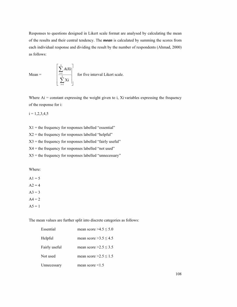
108
Responses to questions designed in Likert scale format are analysed by calculating the mean
of the results and their central tendency. The mean is calculated by summing the scores from
each individual response and dividing the result by the number of respondents (Ahmad, 2000)
as follows:
Mean =
⎥⎥⎥⎥
⎦
⎤
⎢⎢⎢⎢
⎣
⎡
∑
∑
=
=5
1
5
1
Xii
i
AiXi for five interval Likert scale.
Where Ai = constant expressing the weight given to i, Xi variables expressing the frequency
of the response for i:
i = 1,2,3,4,5
X1 = the frequency for responses labelled “essential”
X2 = the frequency for responses labelled “helpful”
X3 = the frequency for responses labelled “fairly useful”
X4 = the frequency for responses labelled “not used”
X5 = the frequency for responses labelled “unnecessary”
Where:
A1 = 5
A2 = 4
A3 = 3
A4 = 2
A5 = 1
The mean values are further split into discrete categories as follows:
Essential mean score >4.5 ≤ 5.0
Helpful mean score >3.5 ≤ 4.5
Fairly useful mean score >2.5 ≤ 3.5
Not used mean score >2.5 ≤ 1.5
Unnecessary mean score <1.5

109
Where calculating the ‘usage level’ of ICT tools for the building design process, the mean
values will be grouped in to the following categories.
Daily mean score >3.5 ≤ 4.0
Weekly mean score >2.5 ≤ 3.5
Occasionally mean score >1.5 ≤ 2.5
Never mean score >0.5 ≤ 1.5
Not applicable mean score <0.5
The standard deviation is a statistic that describes how tightly the data are clustered around
the mean. When the data are tightly bunched together and the bell-shaped frequency
distribution curve is leptokurtic, the standard deviation is small. When the data are spread
apart and the frequency distribution curve is mesokurtic, the standard deviation is quite large
(RobertNiles.com).
Standard deviation = ( )
2
22
nxxn∑ ∑−
Where,
X = one value in the set of data;
n = the number of values in the data

110
4.5 SUMMARY
This chapter has described the selection and justification of Delphi survey as the primary data
collection methodology for the purpose of this study. Topics reviewed include: the Delphi
process; evaluation of Delphi; objective of Delphi for this study; Internet based Delphi
survey; Delphi panel selection criteria; recruitment procedure; description of the Delphi panel;
and the Delphi rounds.
The proposed data analysis procedures are described. “Descriptive statistics” were used as the
basic analytical approach. Responses to questions designed in Likert scale format were
analysed by calculating the mean of the results and their central tendency.
The next chapter will focus on the analysis of results collected from the four rounds of Delphi
survey.

111
5 DELPHI SURVEY: ANALYSIS AND RESULTS
5.1 INTRODUCTION
This study aims to better understand how Information and Communication Technology (ICT)
is being implemented during the building design process and its future usage in five years
time. A Delphi panel of 10 experts chosen from the building industry was invited to assist in
answering the following research questions:
How do design professionals perform their work with the assistance of ICT?
To what extent do building design professionals use ICT?
What are the current barriers to the implementation of ICT tools?
What are the impacts of ICT implementation by building design professionals
during design process?
What value is added by the use of ICT tools for building design management?
How can process mapping be used to describe and document the ICT
implementation methodology during the building design process?
Can a best practice model be mapped for ICT use during the design process?
What are the future trends of ICT implementation during building design process?
The data from the four rounds of Delphi survey are presented and analysed on a round by
round basis in this chapter.
5.2 DELPHI ROUND 1
Following on the scrutiny and advice of staff from the School of Property, Construction and
Project Management, RMIT University, the Round 1 questionnaire (refer to Appendix-C) was
modified and distributed to the Delphi panel.
The Delphi Round 1 questionnaire survey began in the second week of October 2004, (11th
October, 2004 – 17th October, 2004). Participants were given one week to complete the web-
based questionnaire. A covering ‘Instruction Letter’ was first sent out via email to provide
participants with information on:
112
A brief introduction on the IDEF0 modelling language;
Instructions for answering the web-based questionnaire;
An assigned personal code for each participant;
The web-link to the Round 1 questionnaire;
A reminder about the submission date for Round 1 questionnaire.
Follow up phone calls were made to ensure all participants had received the email message
and that they were aware of the submission date for the Round 1 survey. Further follow up
telephone calls were made to panel members who had not responded by the due date. Round 1
of the Delphi survey took two weeks to complete. Response data were entered into
spreadsheet format for descriptive analysis.
The Delphi round 1 survey comprised three sections which sought both quantitative and
qualitative data. Section A collects demographic information. Section B looks at the extent of
ICT tools used during the building design process; while section C allows participants to add
in any activities which they believe have been omitted in section B. The results for all three
sections of Round 1 are presented below.
Response: Round 1 Section A
This section collected demographics information about the participants. The collected data is
presented in Table 5-1.
A wide variation existed in participants’ experience in the construction industry including:
architect, engineer, quantity surveyor, academic, researcher, client’s representative and IDEF0
expert, ranging from 5 to 34 years, with 1 expert having 5 years of experience, 2 having
between 6 and 10 years of experience, 4 experts having more than 20 years of experience, and
3 having more than 30 years of experience in the construction industry. Six of the ten Delphi
panel members had participated in research, published, or led workshops related to their fields
of practice. On the basis of the data, none of the panel members could be disqualified through
lack of experience.
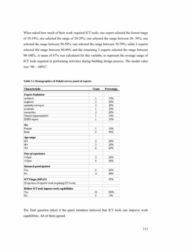
113
When asked how much of their work required ICT tools, one expert selected the lowest range
of 10-19%; one selected the range of 20-29%; one selected the range between 30- 39%; one
selected the range between 50-59%; one selected the range between 70-79%; while 2 experts
selected the range between 80-89% and the remaining 3 experts selected the range between
90-100%. A mean of 67% was calculated for this variable, to represent the average usage of
ICT tools required in performing activities during building design process. The modal value
was “90 – 100%”.
Table 5-1 Demographics of Delphi survey panel of experts
The final question asked if the panel members believed that ICT tools can improve work
capabilities. All of them agreed.

114
Response: Round 1 Section B
Section B of the Round 1 Delphi survey looked at the level of ICT currently used during the
building design process, and sought participants’ forecasts for ICT use five years ahead. This
provided baseline references from which to measure shifts in the responses for subsequent
rounds. Analysis of results for this section is presented together with the responses received in
the final Delphi round (see Table 5-10 and Table 5-12).
Section B contained forty Likert-scale questions. Delphi panel members were asked to select
a five-point Likert-scale interval to represent their opinion of the extent of usage (current and
future) of ICT tools for performing each of the 40 lower level activities listed for the building
design process. The five intervals for the Likert scale were:
(5) Essential – you believe this tool allows project participants to perform work
that was not possible before;
(4) Helpful – you believe this tool significantly decreases effort and makes things
much more efficient and of better quality;
(3) Fairly useful – you believe this tool is useful in performing the job;
(2) Not used – you are not currently using this tool, but it could be used and you
have interest on using it in future;
(1) Un-necessary – you have no interest in this tool and it is not needed to be used
in the future.
Response: Round 1 Section C
The Delphi panel participants were asked to suggest additional activities which should be
included in the building design process map. The responses were summarised, assigned
activity codes, and are shown in Table 5-2.

115
Table 5-2 Summary Result for Round 1 Section C: additional process activities suggested by panellists
Activity No. Description
A112 Site analysis
A116 Seek client’s initial feedback
A121 Identify potential resale target/buyer
A131 Review concept brief
A133 Highlight mismatches and risks
A141 Ensure outline plan fulfils project brief
A143 Review authorities’ requirements
A145 Assess client’s initial feedback
A151 Development of Opinion of Probable Cost and Program (OPC)
A152 Engineering cost studies/ liaise with engineers
A213 Coordinate/liaise with all consultants
A223 Gather feedback from all authorities and consultants
A311 Prepare detailed architectural drawings
A323 Identify and analyse life cycle cost
Fourteen additional activities were suggested by the Delphi experts during the first round
survey. These activities were incorporated into the Round 2 questionnaire survey.
Comment was received from panel member D05, who stated:
“Generally speaking, most design and evaluation activities are reliant on expertise and
experience. Whilst gathering of reference material and communication can occur using IT
systems and can be very useful, however, they will not replace the design team’s ability and
knowledge.”
Although ICT tools are widely used during the building design process, and many
professionals rely on these tools when dealing with everyday tasks, decision making is still
based on individual team members’ professional knowledge, experience and expertise. ICT
tools are used to inform and confirm or reject professional judgement.
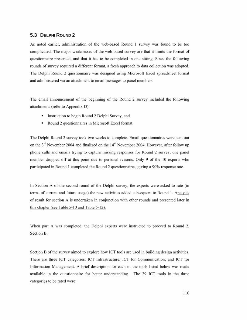
116
5.3 DELPHI ROUND 2
As noted earlier, administration of the web-based Round 1 survey was found to be too
complicated. The major weaknesses of the web-based survey are that it limits the format of
questionnaire presented, and that it has to be completed in one sitting. Since the following
rounds of survey required a different format, a fresh approach to data collection was adopted.
The Delphi Round 2 questionnaire was designed using Microsoft Excel spreadsheet format
and administered via an attachment to email messages to panel members.
The email announcement of the beginning of the Round 2 survey included the following
attachments (refer to Appendix-D):
Instruction to begin Round 2 Delphi Survey, and
Round 2 questionnaires in Microsoft Excel format.
The Delphi Round 2 survey took two weeks to complete. Email questionnaires were sent out
on the 3rd November 2004 and finalized on the 14th November 2004. However, after follow up
phone calls and emails trying to capture missing responses for Round 2 survey, one panel
member dropped off at this point due to personal reasons. Only 9 of the 10 experts who
participated in Round 1 completed the Round 2 questionnaires, giving a 90% response rate.
In Section A of the second round of the Delphi survey, the experts were asked to rate (in
terms of current and future usage) the new activities added subsequent to Round 1. Analysis
of result for section A is undertaken in conjunction with other rounds and presented later in
this chapter (see Table 5-10 and Table 5-12).
When part A was completed, the Delphi experts were instructed to proceed to Round 2,
Section B.
Section B of the survey aimed to explore how ICT tools are used in building design activities.
There are three ICT categories: ICT Infrastructure; ICT for Communication; and ICT for
Information Management. A brief description for each of the tools listed below was made
available in the questionnaire for better understanding. The 29 ICT tools in the three
categories to be rated were:

117
ICT Infrastructure
Internet;
Intranet;
Extranet;
Window;
Personal Area Network (PAN);
Bluetooth;
Information Exchange Standard (IES);
Authentication;
Digital Signature;
Cryptography;
ICT for Communication
Email;
Chat;
Videoconferencing;
Groupware Solution;
Workflow Solution;
Personal Digital Assistant (PDA);
Personal Area Environment (PDE);
Visualization;
Virtual Reality (VR);
ICT for Information Management
Word processor;
Spreadsheet;
Database;
Computer Aided Design (CAD);
3D Modelling;
Hardcopy data;
Multimedia;
Artificial Intelligence (AI);
Electronic Data Interchange (EDI); and
Digital Pen.

118
Each of these tools was to be rated once for each building design activity using the following
scale:
4 = Daily
3 = Weekly
2 = Occasionally
1 = Never
0 = Not Applicable
All experts were asked to first give their ‘overall rating’ (level of usage of each tool to the
building design activities) for each of these tools for the activities listed. Then, they were
asked to rate the individual tools to each activity accordingly.
Finally in Round 2, Section C of the questionnaire allowed Delphi experts to add in ICT tools
not already covered in the list. Comments were also invited.
Response: Round 2 Section B
The response ratings for the twenty nine ICT tools and building design activities are
summarized and presented in Table 5-3 and Table 5-4. The mean rating response value for
each of these tools is first calculated. Then the ICT tools that the Delphi experts rated as being
used during building design process were rank-ordered according to the mean rating values, in
descending order from 4.00 to 0.78. This process was repeated for the experts’ opinion about
future use of the ICT tools.
The highest current usage level of ICT tools was found to be ‘email’ under the “ICT for
Communication” category. The mean rating value for ‘email’ was 4.00; followed by word
processor and spreadsheet, indicating almost daily use of these tools for all Delphi experts
during the building design process. Of the total 29 tools used, 10 were rated 2.5 or higher,
indicating frequent use (at least once every few days). Twelve tools scored mean value ratings
below 1.5, indicating that the Delphi experts have never or only occasionally used those tools
during the building design process.
119
Table 5-3 Current Usage level of ICT Tools Table 5-4 Future Usage level of ICT Tools
5 -3 Current Use 5-4 Future Use
C1 Mean - C3 ICT Tools ICT Tools Mean -F4 F2
1 4.00 Email Email 4.00 1
2 3.89 Word processor Word processor 3.89 2
3 3.56 Spreadsheet Spreadsheet 3.56 3
4 3.44 Hardcopy data Internet 3.56 3
5 3.22 Window Intranet 3.33 5
6 3.11 Internet Window 3.33 5
7 2.89 Database Database 3.22 7
8 2.67 CAD Hardcopy data 3.22 7
8 2.67 Intranet PDA 3.11 9
10 2.56 PDA IES 3.11 9
11 2.44 IES CAD 2.89 11
12 1.89 Extranet Bluetooth 2.67 12
12 2.22 Authentication Authentication 2.56 13
14 1.78 Multimedia Videoconferencing 2.56 13
15 1.67 Videoconferencing PDE 2.56 13
16 1.56 3D modelling 3D modelling 2.56 13
16 1.56 EDI Multimedia 2.56 13
18 1.44 Bluetooth Extranet 2.44 18
18 1.44 Groupware solution. EDI 2.44 18
20 1.33 PAN Digital Signature 2.33 20
20 1.33 Digital Signature Chat 2.33 20
22 1.22 Workflow solution. PAN 2.22 22
22 1.22 PDE Groupware solution. 2.22 22
22 1.22 Visualisation Cryptography 2.11 24
25 1.11 Chat Visualisation 2.11 24
25 1.11 VR VR 2.00 26
27 1.00 Cryptography Workflow solution. 1.89 27
27 1.00 Digital Pen Digital Pen 1.78 28
29 0.78 AI AI 1.67 29
2
rank-order of Mean of experts’ rating 4
Mean values for future use rating
1 rank-order of Mean of experts’ ratings
3 Mean values for current use rating

120
According to Table 5-4, email, word processor and spreadsheet were still ranked highest when
panel experts were asked to predict future usage of ICT tools (for the next five years). On the
other hand, their predictions for the use of the Internet increased from a mean value of 3.11
(current) to 3.56 (future), signifying future almost daily use of such tools. All of the 29 tools
were predicted to be adopted to accomplish building design activities in the future.
Usage Level of ICT tools
0.000.50
1.001.50
2.002.50
3.003.50
4.004.50
Inte
rnet
Intra
net
Extra
net
Win
dow
PAN
Blue
toot
h
IES
Aut
hent
icat
ioin
Dig
ital S
igna
ture
Cryp
togr
aphy
Emai
l
Chat
Vid
eoco
nfer
enci
ng
Gro
upw
are
solv
.
Wor
kflo
w so
lv.
PDA
PDE
Visu
alisa
tion
VR
Wor
dpro
cess
or
Spre
adsh
eet
Dat
abas
e
CAD
3D m
odel
ling
Har
dcop
y da
ta
Mul
timed
ia AI
EDI
Dig
ital P
en
ICT tools
Mea
n Va
lue
Current Mean Future Mean
Figure5-1 Current and Future Usage Level of ICT tools during Building Design Process
Noticeable changes in the mean values of ratings from current to future usage occurred for the
following tools (refer to Figure 5-1):
PAN – mean value increased from 1.33 to 2.22, indicating occasional or even
weekly use of the tool in the future, compared to current occasional use / never
used.
Bluetooth – mean value increased from 1.44 to 2.67, indicating occasional to
weekly usage of the tool in the future compared to current occasional use / never
used.
Digital Signature – mean value increased from 1.33 to 2.33, indicating an
occasional or even weekly use of the tool from current occasional use / never used.
Cryptography – mean value increased from 1.0 to 2.11, indicating occasional use
of the tool in the future, compared to current never used.
Chat - mean value increased from 1.11 to 2.33, indicating occasional or even
weekly use of the tool in the future, compared to current occasional use / never
used.
Videoconferencing - mean value increased from 1.67 to 2.56, indicating occasional

121
to weekly use of the tool in the future, compared to current occasional use / never
used.
PDE - mean value increase from 1.22 to 2.56, indicating occasional to weekly use
of the tool use in the future, compared to current occasional use / never used.
Response: Round 2 Section C
In Section C of the Round 2 questionnaire, specific examples were sought from the Delphi
experts on the three categories of ICT (current and future use) to accomplish each of the
activities during the building design process.
The examples provided by the Delphi experts were primarily concerned with the use of ICT
tools for communication and information management. Mobile communication tools such as
the new generation cellular telephony, e.g., “… experts are now using XDA II by O2 which
allows digital photos to be taken on site, and facilitate assessment and valuations for progress
claims, insurance replacement valuation, tax and depreciation schedules, etc.” Other
examples of the use of new generation telephony include communication by cellular
telephone via Bluetooth technology for sending emails and browsing information on line.
Visualization tools that enhance communication with clients were also mentioned, and
included tools such as 4D CAD and Geographical Information Systems: “… these tools have
been used to present concept design idea to clients beyond those in CAD documentation and
emails.”
Examples of Information Management tools included: document management systems,
construction planning or management tools (MS Project, etc.), 4D CAD applications, and cost
planning tools: “… use of technology allows better information management during the
building design process, real time information retrieval, and better budgeting.”
Another ICT tool suggested by the Delphi expert included Voice over Internet Protocol
(VoIP): “VoIP which will probably be applicable to infrastructure and communication, being
the convergence of data and voice on local networks.”
This concluded the second Delphi round.

122
5.4 DELPHI ROUND 3
The email notice announcing the beginning of Delphi Round 3 was sent out on the 22nd
November 2004. The message included “Instructions for Round 3” in Word document format
and the “Round 3 Survey Questions” in Excel format. Copies can be found in Appendix-E.
The Delphi experts were recommended to print out the instructions for easy reference while
making their responses to the Round 3. Section A of the Round 3 survey questionnaire was
designed in three blocks, looking at ‘current’ issues for ICT application during the building
design process. Block 1 of Section A covered 54 activities during the building design process
(made up from the original 40 activities of Round 1 plus the 14 activities added by the Delphi
experts). The Round 2 ICT tool rating score values were provided for each activity and the
Delphi panel members were asked to review and reconsider their original ratings for current
and future usage. Again, results for this section are analysed with the final responses in Round
4 and presented in section 5.5 (Experts’ perception of ICT implementation during the
Building Design Process, see Table 5-10 and Table 5-12).
Block 2 of Section A looked at the experts’ perceptions about how ICT tools could help them
accomplish each activity during the building design process (current and future). Value added
issues were indicated to allow the experts to choose from the following scale intervals.
C = Cost efficiency (able to produce more with lower cost).
T = Time efficiency (able to produce more in shorter time period).
Q = Quality (able to perform the task in better quality than it previously was and
with less effort).
O = Opportunity (able to perform task that may not have been previously done).
Block 3 of Section A aimed to explore the barriers for ICT implementation during building
design activities (currently and five years hence). The Delphi experts were required to
indicate from the following scale:
T = Lack of Training for soft/ hardware implementation.
C = Cultural barriers such as: threat of ICT; project based nature of construction
project; and adversarial culture between project professionals.
A = Lack of Availability of some soft/ hardware.

123
L = Legal issues such as security.
S = Lack of top management Support.
I = Lack of Investment in soft/hardware.
Comments and suggestions from Delphi experts were invited in the final section of the
questionnaire. An extension of time was given to allow the panel experts another week to
cope with their tight schedules. Of the nine experts who responded to the Delphi Round 2, all
completed the Round 3 questionnaire.
Response: Round 3 – Value Added nature of ICT Implementation
The most frequently selected value added issues for current use of ICT tools by the majority
of experts were time and quality, followed by cost and opportunity (refer to Tables 5-5 and 5-
6). The highest percentage was 78% for all of those issues listed (activities highlighted in
“yellow”). ‘Cost efficiency’ was popular with panel members for activity A141-Ensure
outline plan fulfils project brief, while ‘time efficiency’ was selected by 78% of the experts
for activity A135-Presentations. ’Quality’ was highly cited by panel members for five
activities: A131-Review concept brief; A132–Allocate costs; A212-Prepare preliminary
engineering design; A311-Prepare detailed architectural drawings; and A312-Develop
detail engineering design. Finally, the highest chosen rate for ‘opportunity’ was found for
activities A115-Conduct environmental analysis and A324-Review optimization of energy
performance.
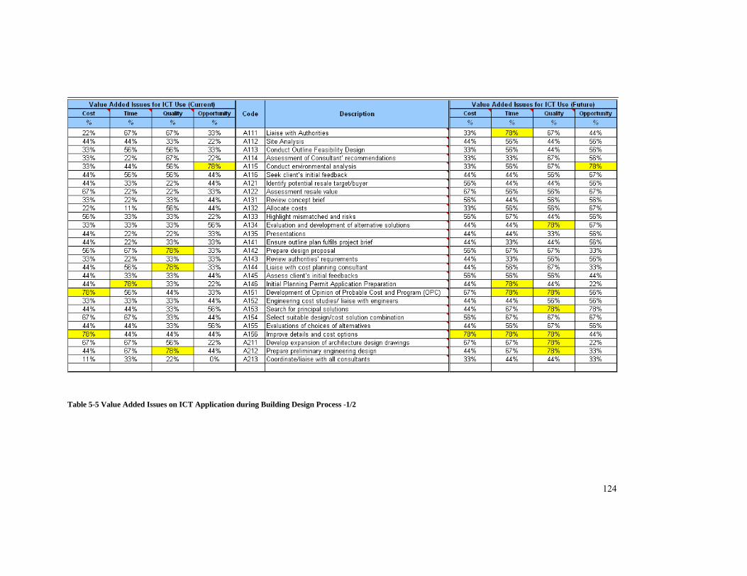
124
Table 5-5 Value Added Issues on ICT Application during Building Design Process -1/2
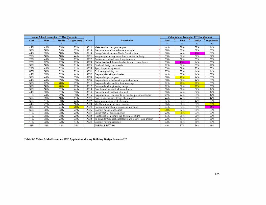
125
Table 5-6 Value Added Issues on ICT Application during Building Design Process -2/2
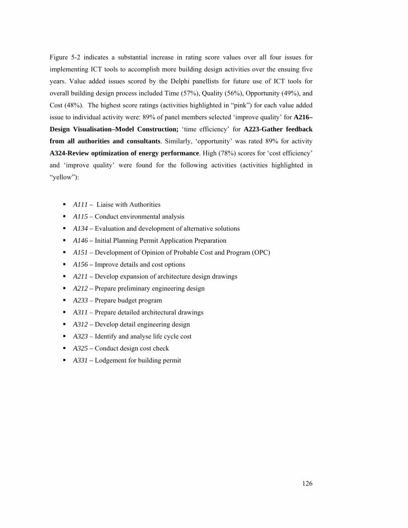
126
Figure 5-2 indicates a substantial increase in rating score values over all four issues for
implementing ICT tools to accomplish more building design activities over the ensuing five
years. Value added issues scored by the Delphi panellists for future use of ICT tools for
overall building design process included Time (57%), Quality (56%), Opportunity (49%), and
Cost (48%). The highest score ratings (activities highlighted in “pink”) for each value added
issue to individual activity were: 89% of panel members selected ‘improve quality’ for A216–
Design Visualisation–Model Construction; ‘time efficiency’ for A223-Gather feedback
from all authorities and consultants. Similarly, ‘opportunity’ was rated 89% for activity
A324-Review optimization of energy performance. High (78%) scores for ‘cost efficiency’
and ‘improve quality’ were found for the following activities (activities highlighted in
“yellow”):
A111 – Liaise with Authorities
A115 – Conduct environmental analysis
A134 – Evaluation and development of alternative solutions
A146 – Initial Planning Permit Application Preparation
A151 – Development of Opinion of Probable Cost and Program (OPC)
A156 – Improve details and cost options
A211 – Develop expansion of architecture design drawings
A212 – Prepare preliminary engineering design
A233 – Prepare budget program
A311 – Prepare detailed architectural drawings
A312 – Develop detail engineering design
A323 – Identify and analyse life cycle cost
A325 – Conduct design cost check
A331 – Lodgement for building permit

127
0%
10%
20%
30%
40%
50%
60%
Percentage
Cost Time Quality Opportunity
Value Added Issues
Overall Rating for Value Added Issues on ICT Implementation During Building Design Process
Current ratingFuture rating
Figure 5-2 Comparison of Current and Future rating for ICT Implementation
Response: Round 3 – Barriers for ICT Implementation
One further issue was explored in the Delphi Round 3 survey. This related to barriers to ICT
implementation during the building design process. Analyses of results are shown in Table 5-
7 and Table 5-8.
The two highest scoring current barriers for ICT Implementation were: ‘lack of availability of
some soft/hardware’ (33% of the Delphi experts) followed by ‘lack of training for
soft/hardware implementation’ (30%). ‘Cultural barriers’ such as: threat of ICT, project
based nature of construction project, adversarial culture between project professionals and
‘lack of investment in soft/hardware’ attracted lower scores (21%). Fewer than 10% of the
participating experts believed that ‘legal’ and ‘support’ issues acted as barriers for ICT
implementation.

128
Table 5-7 Barriers for ICT Implementation during Building Design Process ½
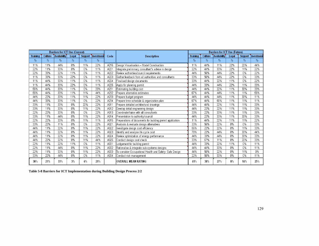
129
Table 5-8 Barriers for ICT Implementation during Building Design Process 2/2

130
In their forecasts for the next five years, the Delphi experts believed that the main barriers for
ICT implementation might refer to ‘training’ and 41% of the experts voted ‘lack of training
for soft/hardware implementation as the main barrier for future ICT implementation.
Following this were: ‘cultural issues’ (38%); and ‘lack of availability’ (27%); ‘lack of
investment’ (25%). Minor increases showed in the voting for ‘legal issue’ (from 3% to 8%)
and ‘lack of top management support’ (from 8% to 15%).
Comparison between the current and future panel opinion ratings for barriers to ICT
implementation revealed the results shown in Figure 5-3. Increases were found for all issues
except ‘lack of availability’. The Delphi experts believe that the availability of soft/hardware
will increase dramatically over the next five years. Importantly however, the Delphi experts
consider that barriers such as lack of training, cultural and legal factors, management support
and investment constraints will continue to impact the adoption of ICT tools in the
foreseeable future. These are issues which the construction industry, including the professions
associated with it, need to address as a matter of urgency if the benefits of ICT
implementation are to be fully realised.
0%
5%
10%
15%
20%
25%
30%
35%
40%
45%
Percentage
Training Culture Availability Legal Support InvestmentImplementation Barriers
Barriers for ICT Implementation
CurrentFuture
Figure 5-3 Comparison of rating on current barriers for ICT implementation and in year 2009.
131
5.5 DELPHI ROUND 4
The email notice to begin Round Four was first sent out on the 18th March 2005. Complaints
were received from respondents regarding their difficulties in understanding and completing
the Round 4 Section A and Section B questions. The, Round Four surveys were then recalled
for review and improved to ensure easier comprehension and answering.
The main problem with the first Round 4 survey was due to the shading of the tabled
summary of Round 3 responses in Section A and Section B (refer to Appendix-F). The Delphi
experts found that the time required in understanding the shading and making decisions was
excessive.
The revised Round 4 survey was pilot tested with staff in the School of Property, Construction
and Project Management at RMIT University before re-distribution. Modifications were made
to Sections A and B, where activities which varied from the common view (mode) were
highlighted in GREEN colour and flagged with a request for reconsideration. Either “Agree
with the Mode” or “Disagree with the Mode” options were given to respondents. Comments
were invited when respondents disagreed with the modal view. Minor changes were also
made to the “Comment made in 3 Rounds by experts” section, and all five questions were
rephrased for better understanding.
The revised- Round Four Delphi surveys were sent out on the 8th April 2005 and requested
responses by 17th April 2005. The message included a “Comment made in 3 Rounds by
experts” file in word document format and the “Revised Round 4 Survey Questions” in Excel
format. Copies are located in Appendix-G.
The Round 4 survey begins with comment on five statements summarised from panel
members in the previous Delphi rounds. Every attempt was made to preserve the original
wording used by the respondents, without sacrificing clarity or brevity. The five statements
made by panel members were:

132
The design and evaluation activities are highly dependent on staff expertise and
experience of individual practices. Whilst ICT has proved beneficial for
communication and information management, it will not replace the expertise and
experience of a design team. Do you agree with the above statements?
The variety and type of ICT infrastructure available in the marketplace is not a
major concern to the industry, because the construction industry is capable of
adjusting its operational processes to suit the available ICT in the marketplace. The
major concern for the industry is whether or not quality improvement could be
achieved by adopting new ICT software. Do you agree with the above statements?
Other ICT tools that should be included are: Visualisation tools (4D CAD, VR,
GIS); Management tools (document management, construction planning, cost
planning, digital photography); and Communication tools (Voice over IP, mobile
communications such as XDAII). Would you agree or disagree that your office’s
productivity can be further enhanced if (any or all of) the above mentioned ICT
tools are used in your current practice?
As the evolution of ICT is so rapid, upgrading your existing software also involves
a major hardware improvement. Do you agree with the above statement?
Do you agree or disagree that the quality and productivity of the building design
process could be further enhanced in the future if an integrated communication
model could be formulated and efficiently implemented among the relevant project
stakeholders?
The Round 4 survey questionnaires aimed to finalise the experts’ ratings on the current usage
level and usage level in year 2009 of ICT tools for the fifty four building design activities
identified and confirmed in the previous rounds. To minimise and to avoid bias of experts’
decision, summaries of panellists’ ratings were presented together with modal values for each
activity. Panel members were invited to compare their own ratings with these statistics (for
both current and future usage).

133
Response: Round 4 – Responses to Five Comments from Delphi Experts
Statement 1- “The design and evaluation activities are highly dependent on staff expertise and
experience of individual practices. Whilst ICT has proved beneficial for communication and
information management, it will not replace the expertise and experience of a design team. Do
you agree with the above statements?”
All Delphi panel members agreed with this statement, and believe that ICT tools facilitate
design practice. Each ICT tool is an increasingly basic and necessary tool for developing
design information, exchange, and testing new concepts. It is also useful for prototyping and
scenario construction and interrogation. However, the extent to which any of these tools can
benefit an organization is highly dependent on the operators’ expertise.
One panellist stated: “Many [ICT] tools have been invented in offices, or by spending
enormous financial resources to secure the best possible intelligence in the market. While
architecture or building design is an intellectually intensive industry, best design can only be
produced by the individual staff member’s past project experience and his/her design talent.
ICT is only a tool that assists our office to improve productivity in general. It can never
replace the importance of each individual designer.”
However, another panellist comments: “… given that all factors are equal, this statement can
be true ... When you have two teams with same design/evaluation skills, one using traditional
design tools, and one using interoperable software that supports quick, automatic/semi-
automatic communications between disciplines, the superiority of the latter is self-
explanatory.”
Statement 2: “The variety and type of ICT infrastructure available on the marketplace is not a
major concern to the industry, because the construction industry is capable of adjusting its
operational processes to suit the available ICT in the marketplace. The major concern for the
industry is whether or not quality improvement could be achieved by adopting new ICT
software. Do you agree with the above statements?”

134
An issue brought out by a panel member was ‘cost’ of implementation, “… availability is
dependant on cost. There are many systems available for consideration, but costs restrict
their use, hence, evolving and adapting to what is available is the norm.” Another panellist
voiced the same concern where cost is the main concern of his company in adapting new
systems and new infrastructure. Costs involved are all types from the capital investment cost
to maintenance costs and training costs.
It was suggested that: “… there is a useful interface role for advanced business service
organizations advising industry as to the appropriate ICT tools to use and training employees
in their application.” By adopting this approach, industry may be keener to adopt changes and
this may also reduce company investment cost.
‘Force’ was another issue pointed out by Delphi members, where they do not believe that the
construction industry is aware of the benefits of ICT and will only use ICT when forced to in
order to stay competitive in the industry. A panellist wrote: “We always need to be aware of
what is available in relation to our clients, consultants and our competitors. We need to
remain up to date and carefully evaluate the introduction of new or updated programs and
hardware. You do not always go with the first thing available.”
Indeed, one panel member brought out an example of the current practice in his organization.
He acknowledged: “…from our past experience of using ICT infrastructure, some of the
functions provided in the ICT application are not useful for our profession. In most cases, we
only utilize approximately 60% to 70% of the available function. Hence in our daily
operation, we have to adjust our working process to suit the ICT in our office. The incentive
for our office to decide whether to adopt a new ICT tool is its ability to improve our internal
productivity.”
Quality improvement could be achieved by adopting new ICT software to some extent, new
organization of people as well as productivity using innovative ICT software could add
benefit to the quality of work. Conversely, knowing about the restrictions and the difficulty of
accessing this development could be helpful.

135
Statement 3- ‘Other ICT tools that should be included are: Visualisation tools (4D CAD, VR,
GIS); Management tools (document management, construction planning, cost planning,
digital photography); and Communication tools (Voice over IP, mobile communications such
as XDAII). Would you agree or disagree that your office’s productivity can be further
enhanced if (any or all of) the above mentioned ICT tools are used in your current practice?”
Again, ‘cost’ and ‘time’ were the two main issues in adopting these tools. First of all,
software/hardware acquisition and training can be costly in the short term. The experts said,
“The extra time, human resource and staff training facilities required to use the new tools can
be costly. In the early stage, the productivity would decrease because the staff is not familiar
with the new tool. It generally takes our office several months to familiarize with a new ICT
tool. But it has been proved to be beneficial for the office productivity in the long-term.”
Legal issues constituted another concern to a panel member. Hard copy data were produced
and kept in record as a back up for those soft data made during the project progress. A panel
expert commented: “Legally speaking, hard copies of all recorded conversations are
required, so there is still an element of double handling with verbal ICT tools.” He further
suggested a mix of those available systems is required to improve productivity. For example,
“cost planning software, CAD, and automated CAD measuring software are sold separately;
a successful combined solution is yet to be marketed.”
One of the Delphi expert believed that: “the use of advanced ICT tools must be a coordinated
effort that is based on workflow and standards that are commonly agreed upon with the
project. If not the case, getting ICT tools with no consideration of others may be an expensive
but not practicable option.”
Statement 4- “As the evolution of ICT is so rapid, upgrading your existing software also
involves a major hardware improvement. Do you agree with the above statement?”
There were opposing views on this statement. Some of the experts believe that better software
usually calls for increased hardware demands. Experts see the major cost factor and barrier is
training staff to adopt the upgraded software. Upgrading existing software also involves a
major hardware improvement. Hardware here involves not only ICT but also people. This has

136
prevented the take up of appropriate software. “They all cost money and people need to be
trained. The usefulness of all these add-ons depends very much on the people using them and
their own design skills. You must never lose sight of the project objectives and too often time
is lost on peripheral activities that do not necessarily help the outcome” (Comment from one
expert).
In contrast, another expert pointed out that, “Technology change comes secondary to the
organizational and process changes”. An example was given based on current practices in his
organization “… we only utilize 60 to 70% of the available function provided in the ICT
software. New functions provide in the upgrade version may not be relevant for our business.”
He further stated that “… upgrading of software always accompanies the need to upgrade our
existing hardware. This further increases our operating cost. However, with all the extra
expense, our productivity has not been upgraded because we do not use much of the new
function in the ICT tool.”
‘Compatibility’ is the major issue to force an upgrading in software and thus hardware. An
expert panel member pointed out that one of the main reasons to incur major upgrading was to
ensure compatible communication with others. “Upgrading existing software and hardware
does not enhance our productivity; however we have to do so to stay compatible with our
stakeholder. For example, if our consultants are all using AutoCAD 2006, we are forced to
upgrade our system to the same level; otherwise we would not be able to read the drawings
they produced.”
Statement 5- “Do you agree or disagree that the quality and productivity of the building
design process could be further enhanced in the future if an integrated communication model
could be formulated and efficiently implemented among the relevant project stakeholders?”
The experts questioned what ‘an integrated communication model’ would mean. Their
feedback was ‘yes’ if the model means systems allowing employees at different points in the
organization to work collaboratively on various aspects of a construction project. However, if
a poorly designed integrated model was adopted, it would result in double or even triple
handling of tasks due to the increased errors and inconsistencies.
137
Some comments seem to disagree with the statement. One panel member stated that: “…
project communication is low at all times and it used to be a lot better. Programs for projects
were generally longer and we had more time to communicate and coordinate… Nothing beats
meeting with the project team on a regular basis and speaking to one another. Too much time
is spent at computer screens sending emails to the person sitting next to you. It takes a
disciplined project leader to make a good project. ICT infrastructure can help but other
things need to be in place first.”
Others suggested that if more user friendly and easily-familiarized integrated communication
tools could be generated, it would definitely help to improve efficiency and to cut down staff
training cost and time.
Response: Round 4 – Experts’ perceptions of ICT implementation during the
Building Design Process
The four rounds of Delphi survey provided useful information about panel members’ decision
making processes in general as well as information about individual practices. Results from
each of the rounds provided baseline references for the research and produced shifts in
respondents’ opinions after feedback from each round was given. However, the primary focus
of this research is based on the final responses from Round 4.
In Round 4, Delphi panel members were asked to give their final ratings for the 54 building
design process activities, in terms of current and future usage levels of ICT tools.
After follow-up encouragement, eight completed responses were received. One respondent
dropped out at this stage due to a tight schedule of work. The quantitative response data from
the Round 4 questionnaire is shown in Table 5-9 for current ICT tool usage and in Table 5-11
for future usage. The mean, mode and standard deviation statistics were calculated for each
process activity. Comparisons of changes in the statistics between Rounds 3 and 4 are
presented in Table 5-10 and for Rounds 1 – 4 in Table 5-12

138
Response ratings for current ICT usage
Table 5-9 shows the expert panellists’ ratings of the usage level of ICT for the 54 building
design activities. These rating were based on 5 point Likert-scales where:
5 = Essential,
4 = Helpful,
3 = fairly useful,
2 = Not used, and
1 = Un-necessary.
The last row in Table 5-9 indicates the Average MEAN rating value for the level of
CURRENT use of ICT during building design process.
Seventeen activities exhibit mean ratings of > 3.5 (see Table 5-9, activities highlighted in
“yellow”), indicating that these ICT tools have decreased effort and made things much more
efficient and of better quality. Ten activities display mean ratings of ≤2.5 (see Table 5-9,
activities highlighted in “grey”), indicating that these ICT tools are not currently used by
panel members, although they could be used and the experts have interest on using them in
future.
During Round 4 of the Delphi survey, some panel members changed their ratings for some of
the activities (Table 5-10). The highest changes were the 29% increase in rating recorded for
activities: A233-Prepared budget program and A314-Presentation to authority/council.
This is followed by a 25% increase for activities: A113-Conduct Outline Feasibility Design
and A145-Assess client’s initial feedback. In contrast, a decrease of more than -10% in the
experts’ rating occurred in the following activities: -20% decrease for A121-Identify
potential resale target/buyer; -16% decrease for A141-Ensure outline plan fulfils project
brief; -15% decrease for A334-Assess foreseeable risk; -13% decrease for A143-Review
authorities’ requirements; and -11% decrease for A151-evelopment of Opinion of
Probable Cost and Program (OPC) and A213-Coordinate/liaise with all consultants. A
7% increase in overall MEAN rating occurred through the increase from 2.97 mean value in
Round 3 to the 3.19 mean rating in the final round.
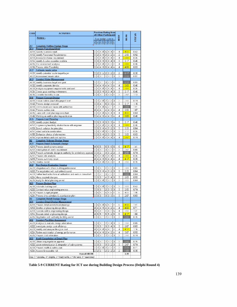
139
Table 5-9 CURRENT Rating for ICT use during Building Design Process (Delphi Round 4)
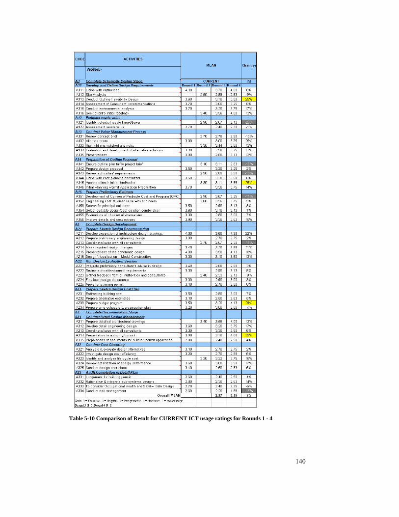
140
Table 5-10 Comparison of Result for CURRENT ICT usage ratings for Rounds 1 - 4
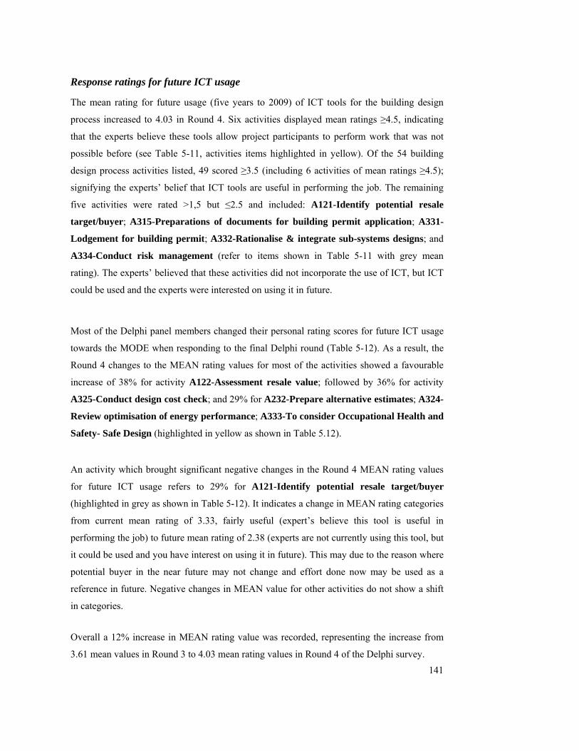
141
Response ratings for future ICT usage
The mean rating for future usage (five years to 2009) of ICT tools for the building design
process increased to 4.03 in Round 4. Six activities displayed mean ratings ≥4.5, indicating
that the experts believe these tools allow project participants to perform work that was not
possible before (see Table 5-11, activities items highlighted in yellow). Of the 54 building
design process activities listed, 49 scored ≥3.5 (including 6 activities of mean ratings ≥4.5);
signifying the experts’ belief that ICT tools are useful in performing the job. The remaining
five activities were rated >1,5 but ≤2.5 and included: A121-Identify potential resale
target/buyer; A315-Preparations of documents for building permit application; A331-
Lodgement for building permit; A332-Rationalise & integrate sub-systems designs; and
A334-Conduct risk management (refer to items shown in Table 5-11 with grey mean
rating). The experts’ believed that these activities did not incorporate the use of ICT, but ICT
could be used and the experts were interested on using it in future.
Most of the Delphi panel members changed their personal rating scores for future ICT usage
towards the MODE when responding to the final Delphi round (Table 5-12). As a result, the
Round 4 changes to the MEAN rating values for most of the activities showed a favourable
increase of 38% for activity A122-Assessment resale value; followed by 36% for activity
A325-Conduct design cost check; and 29% for A232-Prepare alternative estimates; A324-
Review optimisation of energy performance; A333-To consider Occupational Health and
Safety- Safe Design (highlighted in yellow as shown in Table 5.12).
An activity which brought significant negative changes in the Round 4 MEAN rating values
for future ICT usage refers to 29% for A121-Identify potential resale target/buyer
(highlighted in grey as shown in Table 5-12). It indicates a change in MEAN rating categories
from current mean rating of 3.33, fairly useful (expert’s believe this tool is useful in
performing the job) to future mean rating of 2.38 (experts are not currently using this tool, but
it could be used and you have interest on using it in future). This may due to the reason where
potential buyer in the near future may not change and effort done now may be used as a
reference in future. Negative changes in MEAN value for other activities do not show a shift
in categories.
Overall a 12% increase in MEAN rating value was recorded, representing the increase from
3.61 mean values in Round 3 to 4.03 mean rating values in Round 4 of the Delphi survey.

142
Table 5-11 FUTURE Rating for ICT use during Building Design Process
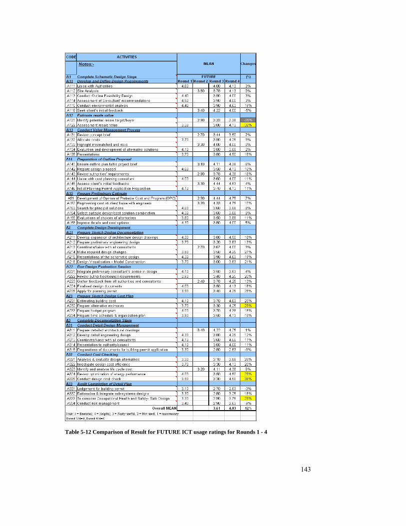
143
Table 5-12 Comparison of Result for FUTURE ICT usage ratings for Rounds 1 - 4

144
5.6 SUMMARY
The data from the four rounds of Delphi survey have been presented and analysed on a round
by round basis in this chapter.
The analysed data will be mapped onto the proposed ‘ICT implementation maps’ of the
building design process and presented in Chapter 6.

145
6 DEVELOPMENT OF THE PROPOSED ICT IMPLEMENTATION MAP
6.1 INTRODUCTION
This chapter describes the development of the ‘ICT implementation map’ and the related
issues.
The data collected from the four rounds of Delphi survey were mapped onto the proposed
‘ICT implementation map’ of the building design process, to represent the Delphi panel
members’ views about current and future trends (in 5 years) of ICT usage. In addition to
indicating the ICT usage level for each of the building design processes (confirmed through
the Delphi survey), the ICT implementation map also focuses on the issues discussed as part
of the Delphi survey. These issues are:
Design communication
Design information management
Information and communication technologies
Impact of ICT
Challenges
6.2 EXTRACTING BUILDING DESIGN ACTIVITIES & THEIR RELATIONSHIPS FROM
IDEF0 MAP
The ‘ICT implementation map’ incorporates the 54 building design activities as discussed in
section 3.5.2. These activities confirmed through the Delphi survey, are extracted from the
IDEF0 map (section 3.4 and 3.5) developed earlier. The building design process activities
include:
A111 – Liaise with Authorities
A112 – Site Analysis
A113 – Conduct Outline Feasibility Design
A114 – Assessment of Consultant’ recommendations
A115 – Conduct environmental analysis

146
A116 – Seek client’s initial feedback
A121 – Identify potential resale target/buyer
A122 – Assessment of resale value
A131 – Review concept brief
A132 – Allocate costs
A133 – Highlight mismatched and risks
A134 – Evaluation and development of alternative solutions
A135 – Presentations
A141 – Ensure outline plan fulfils project brief
A142 – Prepare design proposal
A143 – Review authorities’ requirements
A144 – Liaise with cost planning consultant
A145 – Assess client’s initial feedbacks
A146 – Initial Planning Permit Application Preparation
A151 – Development of Opinion of Probable Cost and Program (OPC)
A152 – Engineering cost studies/ liaise with engineers
A153 – Search for principal solutions
A154 – Select suitable design/cost solution combination
A155 – Evaluations of choices of alternatives
A156 – Improve details and cost options
A211 – Develop expansion of architecture design drawings
A212 – Prepare preliminary engineering design
A213 – Coordinate/liaise with all consultants
A214 – Make required design changes
A215 – Presentations of the schematic design
A216 – Design Visualisation – Model Construction
A221 – Integrate preliminary consultant’s advise in design
A222 – Review authorities/council requirements
A223 – Gather feedback from all authorities and consultants
A224 – Finalised design documents
A225 – Apply for planning permit
A231 – Estimating building cost
A232 – Prepare alternative estimates
A233 – Prepare budget program
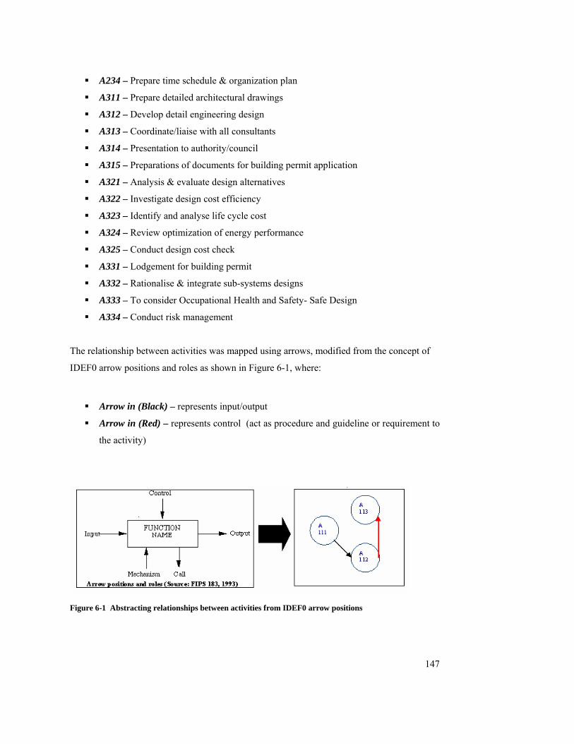
147
A234 – Prepare time schedule & organization plan
A311 – Prepare detailed architectural drawings
A312 – Develop detail engineering design
A313 – Coordinate/liaise with all consultants
A314 – Presentation to authority/council
A315 – Preparations of documents for building permit application
A321 – Analysis & evaluate design alternatives
A322 – Investigate design cost efficiency
A323 – Identify and analyse life cycle cost
A324 – Review optimization of energy performance
A325 – Conduct design cost check
A331 – Lodgement for building permit
A332 – Rationalise & integrate sub-systems designs
A333 – To consider Occupational Health and Safety- Safe Design
A334 – Conduct risk management
The relationship between activities was mapped using arrows, modified from the concept of
IDEF0 arrow positions and roles as shown in Figure 6-1, where:
Arrow in (Black) – represents input/output
Arrow in (Red) – represents control (act as procedure and guideline or requirement to
the activity)
Figure 6-1 Abstracting relationships between activities from IDEF0 arrow positions
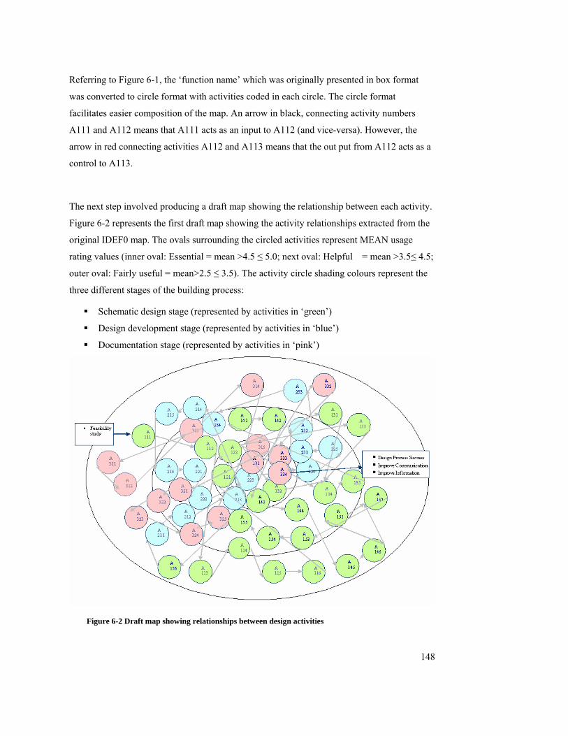
148
Referring to Figure 6-1, the ‘function name’ which was originally presented in box format
was converted to circle format with activities coded in each circle. The circle format
facilitates easier composition of the map. An arrow in black, connecting activity numbers
A111 and A112 means that A111 acts as an input to A112 (and vice-versa). However, the
arrow in red connecting activities A112 and A113 means that the out put from A112 acts as a
control to A113.
The next step involved producing a draft map showing the relationship between each activity.
Figure 6-2 represents the first draft map showing the activity relationships extracted from the
original IDEF0 map. The ovals surrounding the circled activities represent MEAN usage
rating values (inner oval: Essential = mean >4.5 ≤ 5.0; next oval: Helpful = mean >3.5≤ 4.5;
outer oval: Fairly useful = mean>2.5 ≤ 3.5). The activity circle shading colours represent the
three different stages of the building process:
Schematic design stage (represented by activities in ‘green’)
Design development stage (represented by activities in ‘blue’)
Documentation stage (represented by activities in ‘pink’)
Figure 6-2 Draft map showing relationships between design activities

149
6.3 IDENTIFY RATING FOR EACH ACTIVITY
The rating for each activity refers to the current usage level of ICT tools during building
design process and the usage level forecast for the future in 5 years time (as perceived by the
Delphi survey participants). The statistics were developed after four rounds of Delphi survey
and calculated as mean values. The mean values were then assigned into discrete categories as
follows:
Essential mean score >4.5
Helpful mean score >3.5 ≤ 4.5
Fairly useful mean score >2.5 ≤ 3.5
Not used mean score >2.5 ≤ 1.5
Unnecessary mean score <1.5
Analyses for ‘current’ usage level of ICT tools, from four rounds of Delphi survey shows that:
No activity was rated under the ICT tool usage category ‘essential’;
33% of the activities were rated under the ICT tool usage category ‘helpful’ including:
A111 – Liaise with Authorities
A113 – Conduct Outline Feasibility Design
A115 – Conduct environmental analysis
A116 – Seek client’s initial feedback
A131 – Review concept brief
A133 – Highlight mismatched and risks
A145 – Assess client’s initial feedbacks
A146 – Initial Planning Permit Application Preparation
A152 – Engineering cost studies/ liaise with engineers
A156 – Improve details and cost options
A211 – Develop expansion of architecture design drawings
A214 – Make required design changes
A215 – Presentations of the schematic design
A233 – Prepare budget program
A311 – Prepare detailed architectural drawings

150
A312 – Develop detail engineering design
A314 – Presentation to authority/council
A323 – Identify and analyse life cycle cost
48% of the activities were rated under the ICT tool usage category ‘fairly useful’
including:
A112 – Site Analysis
A114 – Assessment of Consultant’ recommendations
A134 – Evaluation and development of alternative solutions
A135 – Presentations
A141 – Ensure outline plan fulfils project brief
A142 – Prepare design proposal
A144 – Liaise with cost planning consultant
A151 – Development of Opinion of Probable Cost and Program (OPC)
A153 – Search for principal solutions
A154 – Select suitable design/cost solution combination
A155 – Evaluations of choices of alternatives
A212 – Prepare preliminary engineering design
A216 – Design Visualisation – Model Construction
A221 – Integrate preliminary consultant’s advise in design
A222 – Review authorities/council requirements
A224 – Finalised design documents
A225 – Apply for planning permit
A231 – Estimating building cost
A232 – Prepare alternative estimates
A234 – Prepare time schedule & organization plan
A313 – Coordinate/liaise with all consultants
A321 – Analysis & evaluate design alternatives
A322 – Investigate design cost efficiency
A324 – Review optimization of energy performance
A325 – Conduct design cost check
A332 – Rationalise & integrate sub-systems designs
19% of the activities were rated under the ICT tool usage category ‘not used’
including:
A121 – Identify potential resale target/buyer
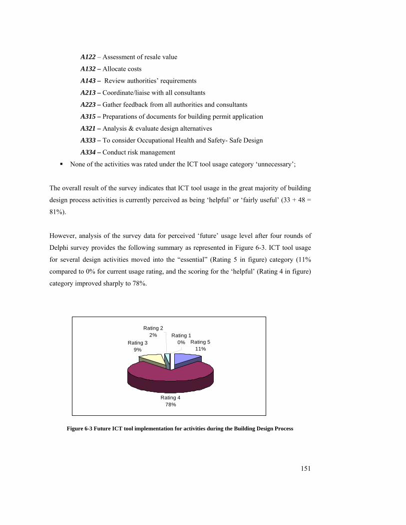
151
A122 – Assessment of resale value
A132 – Allocate costs
A143 – Review authorities’ requirements
A213 – Coordinate/liaise with all consultants
A223 – Gather feedback from all authorities and consultants
A315 – Preparations of documents for building permit application
A321 – Analysis & evaluate design alternatives
A333 – To consider Occupational Health and Safety- Safe Design
A334 – Conduct risk management
None of the activities was rated under the ICT tool usage category ‘unnecessary’;
The overall result of the survey indicates that ICT tool usage in the great majority of building
design process activities is currently perceived as being ‘helpful’ or ‘fairly useful’ (33 + 48 =
81%).
However, analysis of the survey data for perceived ‘future’ usage level after four rounds of
Delphi survey provides the following summary as represented in Figure 6-3. ICT tool usage
for several design activities moved into the “essential” (Rating 5 in figure) category (11%
compared to 0% for current usage rating, and the scoring for the ‘helpful’ (Rating 4 in figure)
category improved sharply to 78%.
Rating 511%
Rating 478%
Rating 39%
Rating 10%
Rating 22%
Figure 6-3 Future ICT tool implementation for activities during the Building Design Process
152
11% of the activities were rated under the ICT tool usage category ‘essential’
including:
A115 – Conduct environmental analysis
A145 – Assess client’s initial feedbacks
A151 – Development of Opinion of Probable Cost and Program (OPC)
A152 – Engineering cost studies/ liaise with engineers
A215 – Presentations of the schematic design
A231 – Estimating building cost
33.33% of the activities were rated under the ICT tool usage category ‘helpful’
including:
A111 – Liaise with Authorities
A112 – Site Analysis
A113 – Conduct Outline Feasibility Design
A114 – Assessment of Consultant’ recommendations
A116 – Seek client’s initial feedback
A122 – Assessment of resale value
A132 – Allocate costs
A133 – Highlight mismatched and risks
A134 – Evaluation and development of alternative solutions
A135 – Presentations
A141 – Ensure outline plan fulfils project brief
A142 – Prepare design proposal
A143 – Review authorities’ requirements
A144 – Liaise with cost planning consultant
A146 – Initial Planning Permit Application Preparation
A153 – Search for principal solutions
A154 – Select suitable design/cost solution combination
A155 – Evaluations of choices of alternatives
A156 – Improve details and cost options
A211 – Develop expansion of architecture design drawings
A212 – Prepare preliminary engineering design
A213 – Coordinate/liaise with all consultants
A214 – Make required design changes
153
A216 – Design Visualisation – Model Construction
A221 – Integrate preliminary consultant’s advise in design
A222 – Review authorities/council requirements
A223 – Gather feedback from all authorities and consultants
A224 – Finalised design documents
A225 – Apply for planning permit
A232 – Prepare alternative estimates
A233 – Prepare budget program
A234 – Prepare time schedule & organization plan
A311 – Prepare detailed architectural drawings
A312 – Develop detail engineering design
A313 – Coordinate/liaise with all consultants
A314 – Presentation to authority/council
A321 – Analysis & evaluate design alternatives
A322 – Investigate design cost efficiency
A323 – Identify and analyse life cycle cost
A324 – Review optimization of energy performance
A325 – Conduct design cost check
A333 – To consider Occupational Health and Safety- Safe Design
9% of the activities were rated under the ICT tool usage category ‘fairly useful’
including:
A131 – Review concept brief
A315 – Preparations of documents for building permit application
A331 – Lodgement for building permit
A332 – Rationalise & integrate sub-systems designs
A334 – Conduct risk management
2% of the activities were rated under the ICT tool usage category ‘not used’ including:
A121 – Identify potential resale target/buyer
None of the activities was rated under the ICT tool usage category ‘unnecessary’.

154
0.00
1.00
2.00
3.00
4.00
5.00A1
11A1
12A1
13A1
14A1
15A1
16A1
21A1
22A1
31A1
32A1
33A1
34A1
35A1
41A1
42A1
43A1
44A1
45A1
46A1
51A1
52A1
53A1
54A1
55A1
56A2
11A2
12A2
13A2
14A2
15A2
16A2
21A2
22A2
23A2
24A2
25A2
31A2
32A2
33A2
34A3
11A3
12A3
13A3
14A3
15A3
21A3
22A3
23A3
24A3
25A3
31A3
32A3
33A3
34
Building Design Activities
Ratin
g
Current Future
Figure 6-4 Current vs. Future rating on ICT implementation during building design process
155
According to Figure 6-4, the experts’ perceptions of future ICT usage in five years time have
increased for all building design activities. This reflects the experts’ belief that ICT tools will
be used more intensively to complete all building tasks in the future, and this may due to
some of the issues discuss below
6.4 IDENTIFY ISSUES FOR IMPLEMENTATION
Issues for implementation were discussed earlier in Chapter 2 section 2.3. Five strands were
first identified from literature review and presented as a series of issues and were further
tested with the panel experts during the Delphi rounds. These issues include:
Design communication – can be distinguished in to three aspects as pointed out by
den Otter and Prins (2002):
o “Face to face/meetings and on distance communication: containing both
verbal and non-verbal communication. Verbal communication refers to
information transferred through short verbal message; whereas non-verbal
communication uses documents or other media.
o Formal and informal communication: communication organized in a
structured way is formal communication. On the other hand, informal
communication refers to information exchange in ways where formal rules and
hierarchies are eliminated.
o Types of information exchange: information exchange can be presented in
different formats. For example, verbal and non-verbal; graphical and non-
graphical; digital and non-digital, etc.”
(den Otter and Prins, 2002)
Design information management – where data can be presented in more than one
format such as:
o Sketches
o Schemes
o Image (visual images and symbols)
o Voice (audio transaction )
o Drawings
o Words

156
Information Communication Technologies (ICT) – classified into three categories:
o ICT infrastructure – covers all hardware and software;
o ICT for communication – to achieve mutual understanding between parties;
o ICT for information management – to organize massive quantity of data.
The impact of technology – both tangible and intangible factors, including:
o Cost efficiency - Duyshart et al. (2003) point to seven major areas of cost that
could be directly affected through the use of information technology
initiatives. These include cost reduction in: plan printing; paper supplies;
photocopier/fax hire; postage/couriers/taxis; photography; interstate travel; and
telephone/mobile.
o Time efficiency – Belmiro et al. (2000) state that a number of benefits arise in
terms of time saving: faster activity times, speeding up of communication
flows; quicker decision making; eliminating travel time; sharing data bases
(global environment); and eliminating intermediates from the communication
process.
o Quality – refers to the ability to perform the task to a higher standard than it
previously was and with less effort. The quality of information exchanged has
improved due to the decrease in data duplication and the time expended in re-
entering received data. The result is more up-to-date information that is often
directly linked into decision-making as well as reporting.
o Opportunity – refers to the ability to perform tasks that may not have been
previously done (or were not capable of being done under existing data
environments). For example: ICT use increases cooperation and enhances
collaborative working because it reduces task uncertainty between two
professionals through the effects on information exchange intensity and
channel formalization. As Stern and Kaufman (cited in, Nakayama, 1999)
argue, “the greater the amount of information exchange, the greater the
possibility for mutual understanding of each other’s goals, which can lead to
increase cooperation.”
The challenges –literature findings (Peansupap and Walker, 2005; Whyte et al., 2002;
Hannus et al., 2003; Kalian et al., 2001; Egbu et al., 2001; Anumba et al., 2002)
suggested that, the barriers to ICT implementation in the workplace fall into four main
157
categories (refer to Chapter 2.3.5). These are:
o Cultural barriers
o Technical barriers
o Management barriers
o Organisational barriers
All the issues discussed above will be mapped in the proposed ICT implementation map
together with 54 building design activities and their rating for current use and future trends in
five years time. The next section focuses on the mapping development process for the
‘current’ and ‘future’ maps.
6.5 DEVELOPING THE ICT IMPLEMENTATION MAP
This section describes the steps required in developing the proposed ICT implementation
map. All the issues discussed earlier in this chapter are brought together in the proposed ICT
implementation map. The steps carried out include:
Activities were grouped according to their mean survey ratings.
Relationships between activities were drawn out using arrow formats (representing
in black for ‘input/out’ and in red for ‘control’).
Issues affecting the level of implementation were identified and mapped.
These processes were first done for the proposed ‘current’ ICT tool implementation map and
then repeated for the ‘future’ ICT tool implementation map.
Figures 6-5 and 6-6 represent the summary findings from the four rounds of Delphi survey.
The 54 activities during building design process are grouped into three stages as:
Schematic design stage (represented by activities in ‘green’)
Design development stage (represented by activities in ‘yellow’)
Documentation stage (represented by activities in ‘pink’)

158
Figure 6-5 Map of Current ICT Implementation during the Building Design Process

159
Figure 6-6 Map of Future ICT Implementation during the Building Design Process

160
All 54 activities were then grouped according to their mean survey ratings where the highest
ratings are grouped in the inner circle and the lowest ratings in the outer circle. The
relationship between activities was linked by arrows in ‘grey’ (represented input/output) or in
‘red’ (representing control).
The five main issues identified were also mapped out in the ICT implementation map
referring to:
Design communication
Design information management
Information communication technologies (ICT)
The impact of technology
The challenges
6.6 SUMMARY
This chapter has presented the development process for the ICT implementation maps. These
maps represent the findings from the four rounds of Delphi surveys. A total of 54 building
design activities were mapped out according to the experts’ perception of the usage level of
ICT tools for each activity for current and future usage over the next 5 years. The ICT
implementation maps will be fine-turned through interviews with experts.
The following chapter presents the main findings from the interviews and shows how the
maps are modified. The implementation of the modified maps will also be discussed
161
7 VALIDATION OF THE BUILDING DESIGN PROCESS MAPS
7.1 INTRODUCTION
The ICT implementation maps (for current ICT usage in the building design process and
predicting future usage over the next 5 years) represent data collected from the Delphi
surveys. This chapter reports the outcomes from a focus group established to test the
robustness of the IDEF0 maps and their underlying concepts.
Interviews were conduct during November 2005. The focus group comprised three experts
selected on the basis of their background and experience. Two experts were selected from the
Delphi panel to participate in the interviews: (1) IDEF0 expert ‘D07’ (2) building designer
‘D08’. A development manager (‘D11’) was new to the research and selected based on his
experience and current involvement in the construction industry.
D11 is currently working as a development manager for a medium-large property
development organization. He graduated with a double degree in Bachelor of Architecture and
Bachelor of Property and Construction from the University of Melbourne, and has more than
5 years experience in design, planning and project delivery of residential and commercial
projects.
7.2 THE INTERVIEWS
This section covers: how interviews were arranged, where interviews were conducted, how
the interviews were conducted, and the analysis process.
7.2.1 Interview Format
A series of semi-formal interviews was conducted with the three experts. The principle reason
for conducting these interviews was to test and to improve the proposed ICT implementation
maps. Participants were contacted by email stating the purpose of the interviews.

162
The interview questions were formatted on a semi-structured basis. The questionnaires
contained six open-ended questions, and took thirty to forty-five minutes for each participant
to complete.
The face-to-face conversation interviews all occurred in each participant’s place of business.
The interview processes were digitally recorded and the data collected were later transcribed
verbatim for analysis. The quantitative data from transcripts were then analysed for similarity
of phrases item by item and are presented in the next section.
7.2.2 Interview Responses
The interview questions and responses are as follows:
1. Do you think the proposed “ICT Implementation Map” is self-explanatory? If not, how
could it be improved?
‘Complicated’ is one of the most important issues raised by the interviewees. They found that
too much information is provided on the maps and may lead to misinterpretation. The IDEF0
expert (D07) responded to this question in depth as she has experience dealing with models
and mapping:
“The map is too complicated for readers as too much information is provided; you need an
explanation for each activities box.
Using hatching to differentiate the ratings seems difficult to read and I recommend shaded
colour instead.
The relationships between activities represented by the arrows are too complicated and the
reader can hardly follow them. I suggest taking out a level of detail as the relationships are
already shown in the IDEF0 map.
I suggest the ‘polyline’ used to group design activities should be shown in one single solid
colour (eg. grey/black), as it will stand out and be clear to the reader.
The formatting of the five issues on the maps does not properly represent them. Some
modification is needed to make them relate to all activities.”
Other comments also related to the complexity of the maps, suggesting where a level of detail
should be omitted from the map for better understanding.
163
2. In your opinion, what are the strengths and weaknesses of using the proposed map as a
guide to implement new ICT tools to a project?
One of the strengths is that a model can be so powerful in sending message to reader. IDEF0
expert (D07) stated that: “A diagram can be powerful in tracking a journey as it shows what
has been done and what has changed in just one view”.
Information presented and mapped out in the model represented information collected from
the four round Delphi survey. Readers can easily and quickly recapitulate the outcomes of the
survey research by looking at the two maps.
Building designer (D08) noted that the ‘current’ and ‘future’ maps provide a comparison base
for present status and future trends for ICT implementation. Comparing the ‘current’ and
‘future’ maps shows a substantial potential increase in the usage level of ICT tools in the
future, with a hint of heavy dependency on technology for conducting future building design
work.
On the other hand, development manager (D11) suggested that: “The proposed maps were
complete in showing how ICT is being used during the building design process, and the issues
indicated will definitely help the decision making processes involved when adopting new
technology”.
The weakness of the models is primarily due to their complexity. Too much information is
compressed into the two maps, resulting in complication and increasing the potential for
misinterpretation. Modifications to the formatting of the maps were necessary.
3. How do you think the proposed “ICT Implementation Map” could help design
professionals in decision making for adopting new ICT tools in the building design
process?
Relating the ICT implementation maps to decision making process brought out several
positive responses. These are summarised as follows:
Focusing on the ‘future’ map, it was clearly shown that there is a need to adopt new
technologies, based on research with different people.
164
The maps show what people want, as a manager or decision maker, it is important to
provide people with the tools, techniques and encouragement, making them more time
rich and efficient.
The proposed maps may act as strong guideline for decision making process. It can be
used as a tool to assess the financial requirement for adopting new ICT tools (e.g.
training cost), potential benefits, possible obstacles, resources required, when
considering adopting a new ICT tool into a practice.
The proposed map shows where ICT resources are currently concentrated, where they
might be needed in 5 years, and what issues will be encountered in aiming towards
those targets. These maps act like triggers to strategic thinking about ICT
implementation for building design professionals.
4. In the Delphi survey, some activities were rated 5, (essential use of ICT tools); meaning
that experts believe that “ICT tools are necessary to allow project participants to perform
work that was not possible before; and these tools will continue to be necessary in the
future”. How do you think ICT tools could be used, or used more intensively, in these
activities?
A115 – Conduct environmental analysis. This activity involves work done to consider the
environmental strengths and weaknesses of the proposed development, and scan the
environment for opportunities on the selected site. This was clearly a design activity area
where the implementation of ICT tools has not yet been fully thought through.
Interviewees believe that this activity has a big influence on risk management where ICT will
help to make environmental or site analyses more accurate, with less time and effort. This
should help to reduce the probability of occurrence of the risk of design failure. ICT tools also
provide a more effective communication medium for various stakeholders.
A145 – Assess client’s initial feedback. This activity involves work done to assess client’s
initial feedback from stage A116.
The IDEF0 expert (D07) gave an example for this activity: “Technology helps an
organization to stay competitive. Most design professionals are time poor. The help of
technologies enables them to work more efficiency and effectively, therefore maintaining
competitiveness.”
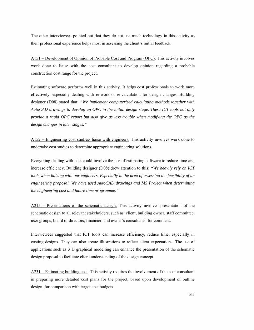
165
The other interviewees pointed out that they do not use much technology in this activity as
their professional experience helps most in assessing the client’s initial feedback.
A151 – Development of Opinion of Probable Cost and Program (OPC). This activity involves
work done to liaise with the cost consultant to develop opinion regarding a probable
construction cost range for the project.
Estimating software performs well in this activity. It helps cost professionals to work more
effectively, especially dealing with re-work or re-calculation for design changes. Building
designer (D08) stated that: “We implement computerised calculating methods together with
AutoCAD drawings to develop an OPC in the initial design stage. These ICT tools not only
provide a rapid OPC report but also give us less trouble when modifying the OPC as the
design changes in later stages.”
A152 – Engineering cost studies/ liaise with engineers. This activity involves work done to
undertake cost studies to determine appropriate engineering solutions.
Everything dealing with cost could involve the use of estimating software to reduce time and
increase efficiency. Building designer (D08) drew attention to this: “We heavily rely on ICT
tools when liaising with our engineers. Especially in the area of assessing the feasibility of an
engineering proposal. We have used AutoCAD drawings and MS Project when determining
the engineering cost and future time programme.”
A215 – Presentations of the schematic design. This activity involves presentation of the
schematic design to all relevant stakeholders, such as: client, building owner, staff committee,
user groups, board of directors, financier, and owner’s consultants, for comment.
Interviewees suggested that ICT tools can increase efficiency, reduce time, especially in
costing designs. They can also create illustrations to reflect client expectations. The use of
applications such as 3 D graphical modelling can enhance the presentation of the schematic
design proposal to facilitate client understanding of the design concept.
A231 – Estimating building cost. This activity requires the involvement of the cost consultant
in preparing more detailed cost plans for the project, based upon development of outline
design, for comparison with target cost budgets.

166
Interviewees suggested that activities related to cost estimating involve many estimating
software applications. Integrating the CAD drawings produced by architects and engineers to
estimating software, in order to calculate the building cost, will improve efficiency and
accuracy.
5. Six out of fifty four activities (11%) from the Delphi survey were rated 3 or lower
(representing a forecast of ‘fairly useful’ or ‘not used’ for ICT tools over the next five
years). How do you think the use of ICT tools could be improved over this period for
these activities?
A131 – Review concept brief. This activity involves work done to review the concept brief
derived from previous stages and to confirm the client’s objectives for the project. These
include outcomes such as: the initial plans, elevations, sections, specification and cost plans of
the proposed facility. It is important to fully understand the concept brief, particularly the
functional space requirements.
Interviewees thought that, since the project had not progressed far at this stage, there was little
rationale for increased ICT usage. However, design risk should reduce with the help of
technology. For example, a more accurate calculation can be provided with technology, to
avoid errors at later stages.
A315 – Preparation of documents for building permit application. This activity involves
preparation of documentation including dimensioned plans, sections and elevations to
adequately describe the design for the purpose of obtaining approval to construct.
Interviewees believe that ICT tools can certainly improve the time required for preparing the
documentation required for permit applications. These tools include 3D CAD drawing, colour
scheme sketch and digitalised shadow diagram program applications, all of which would all
improve the productivity in this stage.
A331 – Lodgement for building permit. This activity refers to the application submitted to the
relevant authority for building approval.

167
Interviewees noted that authorities such as local councils were heavily paper based, and most
application need to be done in paper hard copy. This can be improved by promoting ‘online
application’, where drawings and application form are submitted electronically. This will not
only simplify the process but will avoid or reduce the cost for paper archival storage in the
long term if all documents were stored electronically.
A332 – Rationalise & integrate sub-systems designs. This activity involves work done to
rationalize and integrate all design sub-systems to make sure there are no conflicts.
Interviewees agree that the adoption of ICT tools to this activity will definitely improve
efficiency and reduce the risk of design co-ordination errors. Building designer (D08)
commented: “An integrated computerised graphical programme that allows the architect
and client to efficiently visualise the proposed sub-systems could certainly be beneficial in
this stage.”
A334 – Conduct risk management. This activity involves work done to assess and balance the
contingencies of risk with their specific contractual, financial, operational and organizational
requirements by transferring through the combination of insurance, risk financing, and
contract indemnification provisions.
Technology can certainly help risk management to be done more accurately, with less time
and effort. For example, the use of computerised planning and scheduling applications such as
MS Project can help in managing the risk of project time over-run.
A121 – Identify potential resale target/buyer. This activity involves work done to identify
potential buyers and to find out the target group.
This activity was rated 2 in the Delphi survey data analysis, which means that ICT tools are
not being used here. Respondents believe that the lower rating may be due to ‘past
experience’. However, analysis of design elements can have huge impact on re-sale values.
For example, ICT tools can help in calculating long-term benefits. Also, a computerised
database of historical resale values could assist identifying potential resale targets.
6. Please speculate on any other ICT developments, which might occur over the next 5 years,
that you think could affect the building design process.

168
Taking into account the trends of increasing “computer literacy”, increasing backgrounds of
higher education in the population, and increasing interest in the use of ICT in the
construction industry, respondents believe that the building design process will become
increasingly computerised in the future. ICT is getting cheaper and more popular, and
building professionals are becoming more adept with it and dependent on it to handle
everyday tasks. They will have to adopt and adapt these technologies to stay competitive, and
to save time and money in the long term.
The use of 3G mobile devices will expand in the future to cater for everyday tasks, to provide
better communication between various stakeholders, and to improve productivity.
7.3 THE MODIFIED MAPS
Figure 7-1 represents the modified map for current ICT implementation during building
design process. Figure 7-2 represents the modified map for future ICT implementation over
the next five years.
Changes made to the original maps were as follows:
Clustering of activities has been transformed to grey polyline, with activities grouped
in single free-form clusters of related activities (For example: activities A111, A112,
A113, A114, A115 staying in a cluster represented the children activities off parent
activity A11).
Arrow representations of ‘Input/output’ and ‘control’ are removed.
Levels of ICT usage are represented by colour shading, where the darker shade in the
inner circle represents the highest rating (5) and shading for decreasing usage
becoming progressively lighter towards the outer circles.
The issues of ICT implementation are re-drawn as an enveloping set of constraints
surrounding the whole building design process.
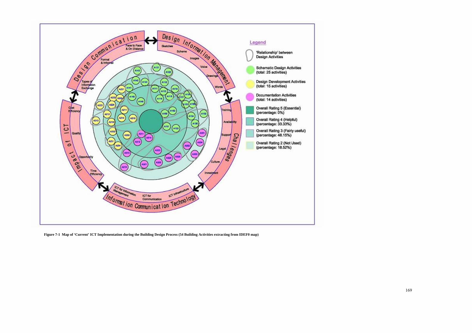
169
Figure 7-1 Map of ‘Current’ ICT Implementation during the Building Design Process (54 Building Activities extracting from IDEF0 map)

170
Figure 7-2 Map of ‘Future’ ICT Implementation during the Building Design Process (54 Building Activities extracting from IDEF0 map)

171
7.4 SUMMARY
This chapter summarises the findings from interviews with three experts. The purpose was to
test the robustness of the proposed ICT implementation maps. Six questions were posed to
focus on the development of the maps. The interview responses showed that the initial maps
were too complicated and time consuming to understand. These responses guided a series of
formatting modifications to the maps.
The following chapter reviews the main findings of the research into ICT and the building
design process, and presents these as a series of conclusions and recommendations.

172
8 CONCLUSIONS AND RECOMMENDATIONS
8.1 INTRODUCTION
This chapter concludes the study of the implementation of information and communication
technologies (ICT) during the building design process. The main findings of the research are
presented, and recommendations are made in terms of changes to current practice and
directions for research. The extent, to which the aims and objectives have been achieved, is
examined.
8.2 SUMMARY OF MAIN FINDINGS
The building design process is a complex process. It requires multi-disciplinary professionals
working together throughout the multi-processes of a building project.
This dissertation has presented the development and validation of ICT implementation maps
focusing on the usage level, the impacts, barriers and other issues of ICT implementation
during the building design process for current practice, and to predict future trends over the
following five year (year 2005 - 2009). The building design process has been mapped out
using IDEF0 process modelling language. This process model was validated and tested by
experts through Delphi survey. Delphi methodology was used in order to move the panel of
experts independently toward acceptable consensus on the issues of implementation. The
fifty-four building design activities were developed from three main stages of the building
design process (Schematic Design; Design Development; and Documentation) to the
following eleven sub-stages:
Complete Schematic Design Stage (A1)
A11 – Develop and Define Design Requirements
A12 - Estimate Resale Value
A13 - Conduct Value Management Process
A14 - Preparation of Outline Proposal
A15 - Prepare Preliminary Estimate
Complete Design Development Stage (A2)
A21 - Prepare Sketch Design Documentation
A22 - Run Design Evaluation Session
173
A23 - Prepare Sketch Design Cost Plan
Complete Documentation Stage (A3)
A31 - Conduct Detail Design Management
A32 - Conduct Cost Checking
A33 - Audit Completion of Detail Plan
A contribution of this study is the development of the ICT implementation maps from current
and future perspectives. The findings of the Delphi experts in four rounds of survey have been
used as input for the development of the ICT implementation maps.
The ICT implementation maps not only provide evidence of the likelihood of increasing use
of ICT tools over the next five years, but also provide a baseline for design professionals or
decision makers in considering the adoption of new technologies to facilitate the process. The
maps show what design professionals believe they will want, and may be used as a tool to
assess the associated issues such as the financial impacts of adopting new ICT tools (e.g.
training costs), potential benefits, possible obstacles to implementation, and resources
required, when considering adopting new ICT tools for design practice.
The outcome from the Delphi survey provided additional evidence that the main barrier to
ICT implementation is ‘cost’. Experts pointed out that: “Availability is dependant on cost.
There are many systems available for consideration, but costs restrict their use, hence,
evolving and adapting to what is available is the norm.” The costs involved include the
capital investment plus the costs of financing, maintenance and training. On the other hand, an
opportunity cost reduction might occur through the promotion of ‘online’ application
processes for planning and building permits from local authorities.
Another finding of this study is related to ‘legal issues’. Hard copy data are produced and kept
as a back up records for the soft data generated by ICT during the project progress. A panel
expert commented: “Legally speaking, hard copies of all recorded conversations are
required, so there is still an element of double handling with verbal ICT tools.” Legal and
cultural change may be required for the industry to move from this reliance on hardcopy
records, and stay competitive in the long term, as discussed in next section.

174
A particular issue emerged during the four round Delphi survey. When asked to comment if
ICT implementation could improve quality and productivity in the building design process,
one expert believed that: “… nothing beats meeting with the project team on a regular basis
and speaking to one another. Too much time is spent at computer screens sending emails to
the person sitting next to you.” This appears to be consistent with Egbu et al. (2001) who
found that many ICT users believe that ‘too much’ computer-mediated communication can
lead to feelings of alienation and frustration. The use of e-mail is frequently cited as being
both indispensable and troublesome. Although it speeds up communication and reduces much
of the need for paper, it can cause ‘interactional difficulties’. This finding is supported by
Rozell and Gardner (2000). It has been suggested that e-mail and other computer mediated
systems, such as video/tele-conferencing, can make people lazy and less likely to partake in
face-to-face communication.
Finally, it is important to note that the proposed “ICT implementation maps” encompass and
represent outcomes from data generated during this research. However, such maps need to be
routinely and systematically updated to ensure that state-of-the-art information is captured and
provided to the construction industry.
8.3 RECOMMENDATIONS FOR PRACTICE
The advocacy of ICT as a means to improve the building design process is accepted by most
of the Delphi survey panel of experts. However, in many respects, the use of technology and
the many developments it can bring are still looked upon with fear and trepidation. People
instinctively resist changes that will have a marked effect on their daily lives. Ways of
enhancing a better understanding of technology and reducing misconceptions are needed to
educate building design professionals to the way that the technology can be adopted. A
number of individual recommendations for the construction industry can be identified from
this research:
Education of building design professionals. Building design professionals need to be
made aware of the wider context of Information and Communication Technology
(ICT) in addition to the traditional applications. An understanding of the broader
context of technology used in the industry will help to facilitate the process.
Education of the construction industry. In general, there is a need to increase
awareness of how ICT can be used to assist a better communication path between team

175
members during the building design process.
Demonstration of IT systems. One of the best ways to convince people of the way that
new technologies can be used is to demonstrate their use. The professional institutions,
suppliers, government, and universities need to establish seminars and workshops, to
demonstrate the appropriate uses of ICT systems.
Promoting continuous improvement. Continuous improvement involves all building
design participants. To facilitate continuous improvement, project stakeholders need to
attain, maintain, monitor and exchange information about the performance of all
participants from the architect to manager as well as site workers in each project, to
learn from experience and to ensure that outcomes meet project requirements.
Recommendation of appropriate technologies. Ongoing independent reviews of ICT
tools implementation during the building design process should be on the agenda of
many professional institutes. Findings from these reviews need to be passed on to the
members of the institutes and to the construction industry in general, to assist in the
selection of appropriate technologies. Communication media such as journals, video-
recordings, and interactive software can be used.
8.4 RECOMMENDATIONS FOR FUTURE RESEARCH
Throughout this thesis, a number of areas were identified for further research. The following
list summarises possible areas for further research.
An in-depth study on security issues in the use of ICT tools for information transfer
and storage during the building design process.
Further study on the problems and barriers of ICT implementation during building
design process focusing on the issues other than management, such as technical issues
and financial issues.
A study of the changes to and development of ICT to help practitioners in different
ways.
Develop process maps, using IDEF0 language, for the building design process for
other procurement method such as design and build.
This research has focused focus on the pre-construction stages of the building design
process. Other stages such as construction stages and post-construction stages should
be taken into consideration. It is recommended to develop process maps, using IDEF0
language, for phases other than pre-construction stage.
176
8.5 ACHIEVEMENT OF RESEARCH OBJECTIVES
The aim of this research was to better understand how Information and Communication
Technology (ICT) is implemented during the building design process. To meet this aim, the
following research objectives were formulated. Six research questions were developed to
address the objectives.
Objective 1 – to examine the manner in which ICT is used by the building design professions
during the building design process (with a focus on large-scale office/commercial projects in
Australia). Research questions two, three and four were developed to accomplish objective 1.
(Research question one was attempted in objective 2)
Research Question Two – What aspects of the work done by design professionals are
influenced by ICT?
Fifty four building design activities were mapped, using IDEF0 process maps. Analysis of
Delphi survey responses for current ICT usage ratings showed that seventeen activities exhibit
mean ratings of > 3.5 indicating that these ICT tools decrease effort and increase efficiency
and output quality. Ten activities display mean ratings of ≤2.5, indicating that ICT tools are
not currently used in undertaking them, although they could be used and experts have an
interest in using them in future.
The Delphi survey responses for ‘future rating’ (five years to 2009) of ICT tools usage for the
building design process showed that six activities displayed mean ratings ≥4.5, indicating that
the experts believe in the capacity of these tools to allow project participants to perform work
that was not possible before. Of the 54 building design process activities listed, 49 scored
≥3.5 (including 6 activities of mean ratings ≥4.5 and the remaining 5 activities achieved rating
<3.5); signifying the experts’ belief that ICT tools are (or could be) useful in performing the
job.
Comparison between the overall mean survey response data values for ‘current’ and ‘future’
ICT usage shows that the mean rating for ‘future usage’ (five years to 2009) of ICT tools for
the building design process was 4.03, compared to 3.19 for ‘current usage’. This indicates
evidence of substantial confidence of the experts in the increasing use of ICT across a range
of building design process activities in the future. This has implications for technology
177
development; technology investment decisions; technology maintenance and upgrading;
staffing; and staff education, training and re-training. These issues were brought out by the
Delphi experts during the Round 4 survey and presented in section 5.5.
Research Question Three – How much do building design professionals use ICT tools?
This question was addressed during Round 2 of the Delphi survey. Findings from the survey
found that the highest current usage level of ICT tools was for email under the ICT for
Communication category. The mean rating value for email was 4.00; followed by word
processing and spreadsheet applications, indicating almost daily use of these tools for all
Delphi experts during the building design process. Of the total 29 tools used, 10 were rated
2.5 or higher, indicating frequent use (at least once every few days). Twelve tools scored
mean value ratings below 1.5, indicating that the Delphi experts had never used those tools
during the building design process. These were:
Bluetooth
Groupware solution
PAN (Personal Area Network)
Digital Signature
Workflow solution
PDE (Personal Digital Environment)
Visualisation
Chat
VR (Virtual Reality)
Cryptography
Digital pen
AI (Artificial Intelligence)
Email, word processing and spreadsheets were still ranked highest when the Delphi survey
panel experts were asked to predict future usage levels for the ICT tools (for the next five
years). However, their predictions for the use of the Internet increased from a mean value of
3.11 (current) to 3.56 (future), signifying future daily use of the Internet. All of the 29 tools
were predicted to be adopted or adapted to accomplish building design activities in the future.

178
Research Question Four - What are the impacts of ICT implementation by building design
professionals during the design process?
The literature review showed that positive (“value adding”) impacts of ICT implementation
by building design professionals during the design process relate to:
Cost efficiency (able to produce more with lower cost).
Time efficiency (able to produce more in shorter time period).
Quality (able to perform the task to higher standard and with less effort).
Opportunity (able to perform tasks that may not have been previously done).
The most frequently selected value added benefits for ‘current’ usage of ICT tools, according
to the majority of experts in the Delphi survey were time and quality, followed by cost and
opportunity.
Analysis of the ‘future usage’ Delphi survey ratings indicates a substantial increase in rating
score values over all four issues.
Negative impacts of ICT implementation could be viewed as ‘barriers to implementation’.
The literature shows that these are:
Lack of training for soft/ hardware implementation.
Cultural barriers such as: threat of ICT; project based nature of construction project;
and adversarial culture between project professionals.
Lack of availability of some soft / hardware.
Legal issues such as security.
Lack of top management support.
Lack of investment in soft / hardware.
The Delphi survey experts believed that ‘lack of availability of some soft/hardware’ and ‘lack
of training for soft/hardware implementation’ are the two main current barriers to ICT usage
in the building design process. However, ‘training’ is forecast to be the main barrier for future
ICT usage and ‘lack of training for soft/hardware implementation’ as the main barrier for ICT
implementation in the future. The Delphi experts believe that the availability of soft/hardware
will increase dramatically over the next five years.
179
Objective 2 – to investigate and map existing design processes using the IDEF0 (Integrated
DEFinition) functional modelling technique. Objective 2 of this study was met by answering
the following question.
Research Question One - How can process mapping being used to describe and document the
building design process?
The main objective of this study is to investigate and to map existing design process and to
propose a model for ICT implementation during the building design process. The conceptual
model type is best suited for this purpose as it represents the variables that are relevant and
shows how they are related. The proposed process model will generally require
decomposition in levels of detail, showing the interrelationship between all variables. IDEF0
modelling language, a process modelling technique based on a well established Structured
Analysis and Design Technique (SADT) was adopted to map the building design process in
this study. The process map was developed to investigate the interrelationships among the
following:
Feasibility studies – produced from the previous stage (as input)
The building design process (as function)
The design process success, to improve communication and information flow (as
output)
The procedures/ guidelines and the requirement to the process (as control)
The ICT tools used and people involved in the process (as mechanism)
Fifty four activities were decomposed from three pre-construction stages stated in Architect
Agreement [Long Form], Scope of Services, RAIA Advisory Note (RAIA, 2000) which
referred to: schematic design stage, design development stage as well as the documentation
stage. These activities were mapped in four levels of an IDEF0 process model for building
design process (refer to Appendix-A).
Objective 3 - to propose a best practice model for ICT implementation during the building
design process that improves information exchange and levels of communication between
participants. The following questions address the above objective.

180
Research Question Five - Can a best practice model be mapped for ICT use during the design
process?
Best practice models for ‘ICT implementation during building design processes (for current
usage and representing forecast future usage trends in five years time) were developed as the
end result of this study (refer to figure 7-1 and 7-2). The maps were derived from the data
collected from the four rounds of Delphi survey. ICT usage levels for each of the building
design processes (identified through the Delphi survey) were shown in these maps. These
maps also depicted the issues discussed as part of the Delphi survey. These issues are:
Design communication
Design information management
Information and communication technologies
Impact of ICT
Challenges
These maps were modified and improved through focus interviews with three building design
experts. Interviewees confirmed that the proposed maps were complete in showing how ICT
is being used during the building design process, and that the issues indicated would help the
strategic decision making process for professional designers when adopting new technology.
Research Question Six - What is the future trend (over five years) of ICT implementation
during the building design process?
The future trend (over five years) of ICT implementation during the building design process
again was shown in the ‘future’ map (Figure 7-2). Respondents believe that the usage of ICT
tools will increase dramatically for most of the building design activities over the next 5
years. Some of the reasons driving this predicted increase in usage level of ICT include: the
increasing cheapness of these technologies; the increased availability of technologies; the
greater capacity of new technologies; the need to integrate and co-ordinate activities with
fellow designers on a project team; and the need to maintain commercial competitiveness.
The aims and objectives of the research are considered to have been achieved.

181
REFERENCES
ABA (1996), Digital Signature Guidelines Tutorial, American Bar Association Section of Science and Technology Information Security Committee. ACADS. (1993), Data Exchange: An Australian Perspective, Association of Computer Aided Design. Ahmad, R.K. (2000), Developing a proactive safety performance measurement tool (SPMT) for construction site, Loughborough University thesis, UK. AIT (1995), Business Process Improvement (Re-engineering): Handbook of Standards and Guidelines, Office of Information Technology: Integrated product Team for Information Technology Services, Version 1.0, Office of Information Technology (AIT), US. Web link: http://www.faa.gov/ait/bpi/handbook/index.htm Anumba,C.J. and Evbuomwan,N.F.O. (1997), Concurrent engineering in design-build projects, Construction Management and Economics,Vol.15, P. 271-281. Anumba,C.J. Baron,G. and Evbuomwan,N.F.O. (1997a), Communication issues in concurrent life-cycle design and construction, BT Technol, Vol.15, No.1, Jan. Anumba,C.J., Baron,G. and Duke,A. (1997b), Information and Communication Technologies to Facilitate Concurrent Engineering in Construction, BT Technol J, Vol.15, No.3, July. Alshawi,M., Underwood,J. (1999), Application of Information Technology in Management or Construction, RICS, UK. Anumba,C.J. and Newnham,L.(2000), Computer-based Collaborative Building Design - Conceptual Model, The International Journal of Construction Information Technology, Vol.8, No.1, p.1-14. Anumba,C.J, Bouchlaghem,N.M. and Whyte (2000), J. Perspectives on an Integration Construction Project Model, International Journal of Cooperative Information Systems, Vol.9, No.3, pp.283-313. Anumba,C.J., Baugh,C. and Khalfan,M.A. (2002), Organisational structures to support concurrent engineering in construction, Industrial Management and Data Systems, Vol.102, No.5, pp.260-270.
182
Aouad, G., Hinks, J., Sheath, D., Cooper, R., Kagioglou, M., and Sexton, M., (1998a), An IT Map for a Generic Design and Construction Process Protocol” Journal of Construction Procurement, Vol.4 No.1, pp 132-151, Nov. Aouad,G., Cooper,R., Kagioglou,M., Hinks,J., and Sexton,M., (1998b), A synchronised process/IT model to support the co-maturation of processes and IT in the construction sector, CIB W78, June, Sweden. Web: http://pp2.dct.salford.ac.uk/publications.htm Austin,S., Balwin,A., Li,B. & Waskett,P., (1999a), Analytical design planning technique for programming the building design process, Proceedings of the Institution of Civil Engineers, Structures and Building, 134, pp. 111 – 118. Austin,S., Balwin,A., Li,B. & Waskett,P., (1999b), Analytical design planning technique: a model of the detailed building design process, Design Studies, N20, pp 279 – 296. Austin,S., Baldwin,A., and Steele,J., (2002), Improving building design through integrated planning and control, Engineering Construction and Architectural Management, V.9 I3, pp. 249 – 258. AS/NZS (1994), Australian/New Zealand Standard: Value management, Standard Australia and Standards New Zealand, Homebush, NSW Barlow, J. and Lowenberg, P. (1999) Bringing construction industry partnering to the regulated sector- The case of the United Kingdom, A report for Windborne International. Brighton, UK.
Belmiro, T. R., Gardiner, P. D., Simmons, J. E. L., Santos, F. C. A., and Rentes, A. F., (2000) Corporate Communications within a BPR Context, Business Process Management Journal, Vol. 6, No. 4, pp. 286-303.
Bennett,B., Cobbold,T. and Philip,M. (2003), ICT use and firm performance in Australia - Evidence from firm interviews, Economic Analysis Industry Policy Division, Australia, September. Bergmann,M.K., Pilskog,G.M. and Hintze, A. (2002), Chap. 3: ICT Infrastructure, Nordic Information Society Statistic. Web: http://www.norden.org/pub/uddannelse/forskning_hojereudd/sk/Julkaisu_final.pdf Best, R and de Valence,G. (1999), Building in Value: Pre-design issues, Holder Headline Group, British.

183
Bone,C. and Law, M. (1997), Value Management- a quick guide: For chief executives and management teams in small and medium sized enterprises, The department of Trade and Industry, UK. Web:http://www.dti.gov.uk/mbp/bpgt/m9bd13001/m9bd130011.html Bouchlaghem, D., Kummance, A.G. and Anumba, C.J. (2004), Integrating product and process information in the construction sector”, Industrial management and data systems, Vol. 104, No.3, Pp. 218-233. BS EN 12973 (2000), British Standard: Value Management, British Standards Institute. BT (1995), Construct I.T.: bridging the gap: an information technology strategy for the United Kingdom construction industry, HMSO, London. Cabaniss, K. (2001), Counselling and Computer Technology in the New Millennium – An Internet Delphi Study, PhD Dissertation, Virginia Polytechnic Institute and State University, USA. Cartlidge, D.P. (1973), Cost Planning and Building Economics, Hutchinson Educational, London, UK. Copeland, K.W. and Hwang, C.J. (1997), Electronic Data Interchange: Concepts and Effects, Internet Society's seventh annual conference (INET'97), June, Kuala Lumpur, Malaysia, Web: http://www.isoc.org/inet97/siteindex.html Cornick, T. (1996), Computer Integrated Building Design, E & FN Spon, London, UK. Costa, C.A., (2000), Future of Sport Management Research: A Delphi Study, PhD Dissertation, The Ohio State University, USA. Creswell, J.W. (2003), Research Design: Qualitative, Quantitative, and Mixed Methods Approaches, 2nd Edition,Sage Publications, London. UK. Dalkey, N. C., (1967) The Delphi Method: An experimental study of group opinion. Report No. RM-5888-PR. Santa Monica, California: The RAND Corporation, June. Dalkey, N. C., with Rourke, D. L., Lewis, R., and Snyder, D., (1972), Studies in the Quality of Life—Delphi and decision-making, Lexington, Massachusetts: Lexington Books. Davison,A., Drake,K., Roberts,W. and Slater,M. (1992), Distributed Window Systems:

184
APractical Guide to XII and Open Windows, Addison-Wesley Publishers Ltd, Great Britain. den Otter, AD.F. and Prins, M. (2002), Architectural design management within the digital design team, Engineering Construction and Architectural Management, Vol. 9, Issue 3, P.162-, June. De Lapp, J., Ford, D.N., Bryant, J.A. and Horlen, J. (2004), Impacts of CAD on design realization, Engineering Construction and Architectural Management, Vol. 11, Issue 4 Domik, G. (2000), Computer Generated Visualization, ACM SIGGRAPH Curriculum for Visualization: On-Line Document, University of Paderborn, Department of Computer Science, Web: http://www.uni-paderborn.de/cs/vis/download/curriculum.pdf Douglas,B.(1992), Data Exchange Standards, Technical Computing, no.71, p.12-14. Duyshart,B., Walker,D., Mohamed,S. and Hampson,K. (2003), An example of developing a business model for information and communication technologies (ICT) adoption on construction projects – the National Museum of Australia project, Engineering, Construction and Architectural Management, Vol 10, Issues3, P.179 – 192. Egan, J. (1998), Rethinking Construction, the Report of the Construction Task Force to the Deputy Prime Minister, John Prescott, on the Scope for Improving the Quality and Efficiency of UK Construction, Department of the Environment, Transport and the Regions, London. Ellis,C and Wainer, J. (1999), Multiagent System: A modern approach to distributed artificial intelligence: ”Chapter. 10-Groupware and computer supported cooperative work”, MIT Press, Cambridge, Massachusetts, London, England. Emmitt,S. and Gorse,C.A., (2003), Construction Communication, Blackwell Publishing Ltd, UK. Egbu, C., Gaskell, C. and Howes, J. (2001), The Impact of culture, motivational factors and organisational structure on the utilisation and exploitation of IT for team working, 10th International Symposium: Construction Innovation and Global Competitiveness, W65/W55, September 9th- 13th, 2002, Cincinnati, Ohio, USA. Faniran, O., Love, P., Treloar, G. and Anumba,C. (2001), Methodological issues in design-construction integration, Logistic Information Management, V14 N5/6, Pp.421 – 426.

185
Ferris, J.K. (1998), Leadership audit of university-based performance art centres – A Delphi Approach, dissertation submitted to University of Maryland at College Park. FIPS 183, (1993), Announcing the Standard for Integration Definition for Function Modelling (IDEF0), U.S. Department Standards and Technology, Federal Information Processing Standards Publication, Report Number FIPS PUB 183). Web: http://www.itl.nist.gov/fipspubs/idef02.doc Fromm, M, (2004), GridSuite2 Manual, University Stuttgart, Denmark, Web: http://www.uni-stuttgart.de/pae/gridsuite/index.php?realm=demo&lang=en GDCPP, (1996), IT Map, University of Salford. Web: http://pp2.dct.salford.ac.uk/processmap.htm Gordon, T.J., (1994), Futures Research Methodology: The Delphi Method, AC/UNU Millennium Project. Goldstein,C. and Heard,R. (1990), Computer Graphics: Principles and Practice, 2nd Ed, Addison-Wesley, Reading. Gorman,M.S. and Stubbs,S.T. (2004), Introduction to Operating Systems, Thomson Course Technology, USA. GSI. (1999), Using Public-key Digital Signatures in Paperless Information Systems, Gradkell Systems Inc. Whitepaper, GSA ADP Conference, May. Gray,C. and Hughes,W. (2001), Building Design Management, Butterworth Heinemann, Oxford. Grout,J, (1998), Using Process Mapping to Identify Patient Safety Hazards in Micro-Systems, Quality and Safety in Healthcare. Web: http://www.campbell.berry.edu/faculty/jgrout/idef0/index.htm Gunaydin,H.M. (1999), Impact of IT on Project Management Functions, PhD. Thesis, Graduate College of the Illinois Institute of Technology. Hannus,M. (1995), Islands of Automation in Construction, Web: http://www.vtt.fi/rte/projects/cic/ratas/islands.html

186
Hannus, M., Blasco, M., Bourneau, M., Bohms, M., Copper, G., Garas, F., Hassan, T., Kazi, A.S., Leinonen, J., Rezgui, Y., Soubra, S., and Zarli, A. (2003), Construction ICT Roadmap, ROADCON, Hassan, T.M. (1996), Simulating Information Flow to Assist Building Design Management, PhD. thesis, Loughborough University, UK Hasselbring,W and Weigand,H. (2001), Languages for Electronic Business Communication: State of the Art, Journal of the Industrial Management & Data Systems, Vol.101, No.5, P.217-227. Hazelrigh, G.A., (1996), Systems Engineering: an Approach to Information-Based Design, Prentice-Hall, Inc., Upper Saddle River, NJ, pp. 63-75,205-210 Hess, G.R., and King, T.J. (2002), Planning open spaces for wildlife: Selecting focal species using Delphi survey approach, Landscape and Urban Planning, Vol 58 Issues 1, P.25-40, Jan. Holcombe,J. and Holcomber,C. (2003), Survey of Operating Systems, McGraw-Hill Companies, California, USA. Howard,L. and Lewis,H. (2003), The development of database system to optimise manufacturing processes during design, Journal of Material Processing Technology, V134, P.374-382. Huijbregts, H.J.J. (2002), Information and Communications Technology for Real Estate Investment Management, PhD. Thesis, Harvard Design School, Cambridge, US. Hunt, V.D. (1996), Process Mapping: How to Reengineer Your Business Processes, Jonh Wiley & Sons Inc, Canada. Initial Graphics Exchange (IGES), National Institute of Standards and Technology. Web: http://www.nist.gov/sc4/national/usa/iges/iges.htm IT Briefly. (1998), Internet Payment Mechanisms, Norman Waterhouse TechLaw Briefly: Information Technology Briefly, Sept, Issue 2. Web: http://www.normans.com.au/ ITU. (2003), Assessment of Telecommunication and ICT Infrastructure in Africa, International Telecommunication Union Telecommunication Development Bureau: Symposium on African ICT Roadmap to achieve Nepad Objectives, Arusha, Tanzania, 1-3 April. Web: http://www.itu.int/ITU-D/afr/events/arusha-ITU-NEPAD/Documents/doc7(elotu-english).pdf
187
Joppe, M. (2001), The Delphi Method (course note), Ryerson University, Toronto, Canada, Web: http://www.google.com/u/ryersonu?q=delphi&domains=ryerson.ca&sitesearch=ryerson.ca John, C.V. (1997), Visualization and Optimization, Kluwer Academic Publishers, USA. Kalian, A., Watson, A., Agbasi, E., Anumba, C., and Gibb, A. (2001), Computer-integrated manufacture of cladding system (CIMclad): ICT usage-current and future, Leeds University, UK. Kagioglou, M., Aouad, G., Cooper, R., and Hinks, J. (1998), The Process Protocol: Process and IT Modelling for the UK Construction Industry, Second European Conference on Product and Process Modelling in the Building Industry, October, Watford, BRE. Web: http://pp2.dct.salford.ac.uk/publications.htm Kelly, J., Male, S. and Graham,D. (2004), Value Management of Construction Projects, Blackwell Publishing, Australia. Kennedy, K.A., (2002), The Academy in 2005 – 2015: A Web-based Delphi Study, PhD Thesis, The University of British Columbia, Canada. Kirk,S.J. and Dell’Isola,A.J. (1995), Life Cycle Costing for Design Professional, McGraw-Hill, New York. Lafon, M.B. (1999), Computer Supported Co-operative Work, Jonh Wiley & Sons Ltd. England. Lankford,W.M. and Johnson,J.E (2000), EDI via the Internet, Information Management & Computer Security, Vol.8, No.1, P.27-30. Laudon,KC. and Laudon,J.P. (1998), Management Information Systems: New Approaches to Organization & Technology, Prentice-Hall International, USA. Laudon,KC. and Laudon,J.P. (2002), Management Information System: Managing the Digital Firm. Prentice-Hall International, USA. Levary, R.R. and Han, D. (1995). Choosing a technological forecasting method. Industrial Management, pp. 14-18.
188
Li, Y. and Wang, S.Q. (2003), A Framework for Evaluating IT Benefits in Construction Companies, The 20th CIBW78 conference on IT in Construction, Waiheke Island, Auckland, New Zealand, April. Lide, D.L. (2001), A Century of Excellence in Measurements, Standards, and Technology - A Chronicle of Selected NBS/NIST Publications, 1901 - 2000, Editor; NIST Special Publication 958, January 2001, Web: National Technical Information Service (NTIS), #PB2000-107702. Linde, R.B. (2001), Making Process Models Usable, Royal Institute of Technology, KTH, Department of Industrial Economics and Management Construction Management and Economics, Stockholm, Sweden. Linstone, H. A., and Turoff, M. (ed.), (1975), The Delphi Method: Techniques and applications, Reading, Massachusetts: Addison Wesley Publishing Co, Canada. LXE Inc, (2003), Bluetooth Whitepaper: Bluetooth Basics, LXE Inc, Web: http://www.lxe.com/pdf/White%20Paper%20-%20Bluetooth%20Basics.pdf Macmillan, S. (2000), Summary Report of the CRISP Design Task Group Workshop, Davis Langdon Consultancy, London, Web: http://www.crisp-uk.org.uk/REPORTS/9918SumR.htm Macmillan, S., Steele, J., Kirby, P., Spence, R., and Austin, S. (2002) Mapping the design process during the conceptual phase of building project , Engineering Construction and Architectural Management, Vol. 9 Issue 3. Mayer, R.J., Painter, N.K., and deWitte, P.S., (1992), IDEF Family of Methods for Concurrent Engineering and Business Re-engineering Applications, Knowledge Based Systems, Inc, TX. McCarthy, T., (1990), AutoCAD express, London: Springer-Verlag. McLeod,R. and Schell,G. (2004), Management Information Systems, 9th edition, Pearson Prentice Hall, New Jersey. Meland, Oystein., (2000), The Design Management Function in Construction Projects, PhD thesis, Norwegian University of Science and Technology, Norway. Microsoft.com, Microsoft homepage, Web: http://www.microsoft.com/ Mitchell, W.J. (1995), City of Bits: Space, place and the Infobahn, MIT Press, Cambridge.
189
MobileComputing.com, Digital Pen, Web: http://searchmobilecomputing.techtarget.com/sDefinition/0,,sid40_gci902015,00.html Mona, L.T., Mark, A.C., David, G.C., and Scott, M.C. (2001), Using Cluster Analysis for Deriving Menu Structures for Automotive Mobile Multimedia Applications, SAE 2001 World Congress, Detroit, Michigan, March 5-8. Moreau, K.A. and Back, W.E. (2000), Improving the design process with information management, Automation in Construction, Vol.10, P.127-140. Munns,A.K. and Bjeirmi,B.F. (1996) The Role of Project Management in Achieving Project Success. International Journal of Project Management. Vol.14, Issue 2, P.81-87 NAAIDT.com, (1995), Web: http://www.naaidt.org.uk Nakayama, M. (1999), Information Technology Impact on Interorganizational Relationships in Marketing Channels: Management of Cooperation, Conflict, and Information Sharing, PhD. Thesis, University of California, Los Angeles. Naoum,S.g. (1998), Dissertation Research and Writing for Construction Students, Butterworth Heinemann, Oxford. NM. (1998), Internet Payment Mechanisms, Information Technology Briefly, Norman Waterhouse, Issue.2, Sept. Peansupap, V. and Walker, D. (2005), Factors affecting ICT diffusion: a case study of three large Australia construction contractors, Engineering, Construction and Architectural Management, Vol.12 No.1, p.21-37. Peri, C.A. (2003), Impact of media on spatial communication: From paper to collaborative virtual environments, Ph.D., University of California, Berkeley. Philips, R. (2000), the architect’s plan of work: for the procurement of feasibility studies, a fully design building project, employer’s requirement or contractor’s proposal, London, RIBA. Pike,M.A. (1995), Using the Internet, 2nd Ed., Que, Indianapolis. Poon, J., Potts, K. and Cooper, P. (2000), Practitioners’ opinions on a new construction
190
process model, RICS Research Paper, University of Wolverhampton. Power, D. J (2003)., A Brief History of Spreadsheets, DSSResources.COM, version 3.5, Web: http://dssresources.com/history/sshistory.html Prasad,R. and Ruggieri,M. (2003), Technology Trends in Wireless Communication, Artech House Publishers, USA. Process Mapping Homepage, (1999),Web: http://www.processmapping.com/Help/history.htm Raftery,J. (1998), From Ptolemy to Heisenberg: quantitative models and reality, Construction Management and Economics, Issue:16, pp. 295 – 302. RAIA, (1993), Practice Note: Scope of the Architect’s Services (AN10.01.101), The Rayal Australia Institute of Architects, Australia. RAIA, (2000), Guide Note: User Guide (AN10.01.100), The Rayal Australia Institute of Architects, Australia. RAIA, (2005), Occupational Health and Safety: safe design (AN13.01.103), The Rayal Australia Institute of Architects, Australia. Rangel,F., (1999), A Survey of Methods in Modelling and Simulation, Arizona State University, Arizona. Rezgui, Y., Body, S., Bouchlaghem, D., Hassanen, M., Cooper, G., Barrett, P. and Austin,S. (2001), A Proposed IT-Based Approach for Managing the Construction Brief Effectively, Proceedings of the CIB - W78 Conference (South Africa). RIBA (Royal Institute of British Architect), (1980), Handbook of Architectural Practice and Management, 4th Edition, RIBA Publication Ltd, London. RIBA (Royal Institute of British Architect), (1991), Architect’s Handbook of Practice Management, RIBA, London. Web: http://www.ribanw.demon.co.uk/outline.htm RIBA (Royal Institute of British Architect), (1995), Architect’s Job Book, RIBA Publication Ltd, London. RIBA (Royal Institute of British Architect), (1999), The RIBA Plan of Work Stages 1999, Web: http://www.ribafind.org/plan.asp

191
Robert Niles.com, Web: http://www.robertniles.com/stats/stdev.shtml Roorda,S. (1999), An introduction to Digital Signatures, Rochester Institute of Technology, Department of Computer Science, Web: http://www.cs.rit.edu/~sjr1521/paper.pdf Rozell, E. and Gardner, W. L. (2000), Cognitive, motivation and affective processes associated with computer-related performance, Computers in Human Behaviour, Vol. 16, p. 199-222 Sackman, H., (1975), Delphi Critique, Lexington, MA, Lexington Books. Schal, T. (1996), Workflow Management for Process Organisations, Vol. 1096 of Lecture Notes in ComputerScience. Springer Verlag, Berlin, Germany, Web: http://citeseer.ist.psu.edu/context/1068888/0 SearchSecurity.com, Web: http://searchsecurity.com Sharma, D.P., Chandramohanan, N.R.and Balasubramanian, R. (2003), Analytical search of problems and prospects of power sector through Delphi Study: case study of Kerala State, India, Energy Policy, Vol. 31 Issue 12, p.1245-1255, September. Shaw, R. (2003), Wireless Networking Made Easy: Everything You Need to Know to Build Your Own PANs, LANs, and WANs, AMACOM, USA. Shen, Q., Li, H. and Deng, Z. (2001), “Intelligent multimedia for expertise-intensive training in construction”, Logistic Information Management, Vol.14, No.5/6, pp.386 – 392. Simpson, J.A and Weiner, E.S.C. (1989) The Oxford English Dictionary, Second edition. Oxford: Clarendon Press (20 volumes) Skutsch, M. and Hall, D. (1973), Delphi: Potential uses in educational planning, (ERIC Document Reproduction Service No. ED 084 559)
StatSoft, Inc. (2004), Electronic Statistics Textbook. Tulsa, OK: Statsoft. Web: http://www.statsoft.com/textbook/stathome.html. Steele, J., Macmillan, S., Austin, S., Kirby, P., and Spence, R. (2000) ‘An internet-based system to support interdisciplinary and inter-organisational collaborative conceptual design’. Procs of CIBSE National Conference, CIBSE2000, Dublin, September..
192
Stewart, R.A. and Mohamed, S. (2003), Evaluating the value IT adds to the process of project information management in construction, Journal of Automation in Construction, Vol.12, Issues 4, p.407-417. Su, D. and Chan, X. (2003), Network support for integrated design”, Integrated manufacturing system, Vol.14, No.6, p. 537-546.
Sun,M. and Howard,R. (2004), Understanding I.T. in Construction, Spon Press-Taylor & Francis Group, London. Tam, C.M. (1999), Use of Internet to Enhance Construction Communication: Total Information Transfer System. International Journal of Project Management, V17 (2), P.107-111 Thompson, A. (1999), Architectural Design Procedures, Second Edition, Arnold, a member of the Hodder Headline Group, London, Great Britain. Thorpe,T., Baldwin,A. Carter,C., Leevers,D. and Madigan,D. (1995), Multimedia Communication in Construction, Civil Engineering Panel, Paper 10630, p.12-16, March. Tull,C. (2002), Introduction to PDA, Anywhere YouGo.com, Web: http://archive.devx.com/wireless/articles/PDA/PDAIntro.asp Turban,E., Rauner,R.K., and Potter,R.E. (2005), Introduction to Information Technology, 3rd Edition, John Wiley & Sons Inc. USA. Wailgum,T. (1998), What are Extranet, CIO Enterprise Magazine, March 15. Web: http://www.cio.com/archive/enterprise/031598_toc.html Wayner,P. (1994), EDI Moves the Data, BYTE, Vol.19, No.10, P121. Wedley, W.C. (1980), Making Delphi Decisions – A new participative approach, Deakin University, Occasional Papers. Weippert, A., Kajewski, S.L., and Tilley, P.A. (2003), The implementation of online information and communication (ICT) on remote construction projects, Logistic Information Management, V16, N5, p. 327-340.

193
WfMC (1996), Workflow Management Coalition Terminology Glossary, Technical Report WFMC-TC-1011, Workflow Management Coalition. Web: http://www.wfmc.org/standards/docs/TC-1011_term_glossary_v3.pdf Whatis?com., Web: http://whatis.techtarget.com/ Whyte, J., Bouchlaghem, D. and Thorpe, T. (2002), ICT implementation in the construction organization, Engineering Construction and Architectural Management, Vol.9, I5-6, p.371 – 377. Williamson,K. (2002), Research methods for students, academics and professionals, Second Edition, Centre for Information Studies, Charles Sturt University, NSW. Wi-FiPlanet.com, Web: http://wi-fiplanet.webopedia.com WMC (1999), The Workflow Management Coalition Specification: Workflow Management Coalition Terminology & Glossary, Workflow Management Coalition, Web: http://www.wfmc.org/standards/docs/TC-1011_term_glossary_v3.pdf Zaneldin, E. (2000), An information model for improving design coordination for building project, PhD Thesis, University of Waterloo, Canada. Ziglio, E. (1996), The Delphi Method and it contribution to decision-making, In Adler,M. & Ziglio,E. (Eds), Gazing into the oracle: the Delphi method and its application to social policy and public health, (p.3-333), Bristol, PA, Jessica Kingsley Publisher, UK. Zimmerman,T.G. (1996), Personal Area Networks: Near-field interbody communication, IBM Systems Journal, Vol.35, N3 & 4, Web: http://researchweb.watson.ibm.com/journal/sj/353/sectione/zimmerman.pdf

194
APPENDIX-A
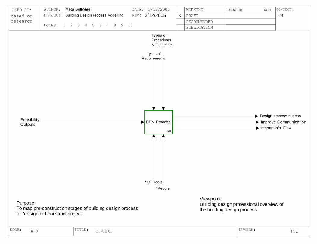
USED AT: CONTEXT:
NODE: TITLE: NUMBER:
AUTHOR:PROJECT:
NOTES: 1 2 3 4 5 6 7 8 9 10
DATE:REV:
WORKINGDRAFTRECOMMENDEDPUBLICATION
READER DATE
P.
Meta Software Building Design Process Modelling 3/12/2005 Top
1
xbased on research
3/12/2005
CONTEXTA-0
BDM Process
A0
FeasibilityOutputs Improve Communication
*ICT Tools*People
Types of Requirements
Types of Procedures & Guidelines
Design process sucess
Improve Info. Flow
Purpose:To map pre-construction stages of building design process for 'design-bid-construct project'.
Viewpoint:Building design professional overview ofthe building design process.

USED AT: CONTEXT:
NODE: TITLE: NUMBER:
AUTHOR:PROJECT:
NOTES: 1 2 3 4 5 6 7 8 9 10
DATE:REV:
WORKINGDRAFTRECOMMENDEDPUBLICATION
READER DATE
P.
Meta Software 3/12/2005
A-0
2
x3/12/2005
BDM ProcessA0
Complete Schematice
Design
A1
Complete Design
DevelopmentA2
Complete Documentation
A3
I1
FeasibilityOutputs
O2Improve Communication
Concept Approved
Client commitmentto proceed
C1Types of Requirements
C2 Types of Procedures & Guidelines
O1Design process sucess
O3Improve Info. Flow
market analysis
Consultant's advice
Client's and End user interviews

USED AT: CONTEXT:
NODE: TITLE: NUMBER:
AUTHOR:PROJECT:
NOTES: 1 2 3 4 5 6 7 8 9 10
DATE:REV:
WORKINGDRAFTRECOMMENDEDPUBLICATION
READER DATE
P.
Meta Software 3/12/2005
A0A0A0
3
x3/12/2005
Complete Schematice DesignA1
I1
FeasibilityOutputs
O1
Concept Approved
Develop&Define Design Requirements
A11
Conduct Value Mgmt
ProcessA13
Preparation of Outline Proposal
A14
Prepare Preliminary
EstimateA15
Client agree to proceed
Feedback-to proceed
Re-addressfunc brief
C1Types of Requirements
C2 Types of Procedures & Guidelines
Outline plancompleted
Concept declined
Estimate Resale Value
A12
Resale valueobtained
I2market analysis
Positive feedback
to proceed
I3Consultant's advice
I4Client's and End user interviews
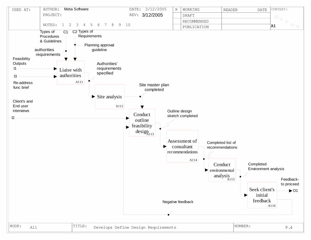
USED AT: CONTEXT:
NODE: TITLE: NUMBER:
AUTHOR:PROJECT:
NOTES: 1 2 3 4 5 6 7 8 9 10
DATE:REV:
WORKINGDRAFTRECOMMENDEDPUBLICATION
READER DATE
P.
Meta Software 3/12/2005
A1A1A1A1A1
4
x3/12/2005
Develop& Define Design RequirementsA11
Liaise with authorities
A111
Conduct outline
feasibility design
A113
Assessment of consultant
recommendations
A114Conduct
environmental analysis
A115
C1 Types of Requirements
I1
FeasibilityOutputs
I3
Re-addressfunc brief
authorities requirements
C2Types of Procedures & Guidelines
Planning approvalguideline
Authorities' requirements specified
Outline design sketch completed
Completed list ofrecommendations
Negative feedback
Site analysis
A112
Seek client's initial
feedbackA116
Site master plancompleted
CompletedEnvironment analysis
O1
Feedback-to proceed
I2
Client's and End user interviews
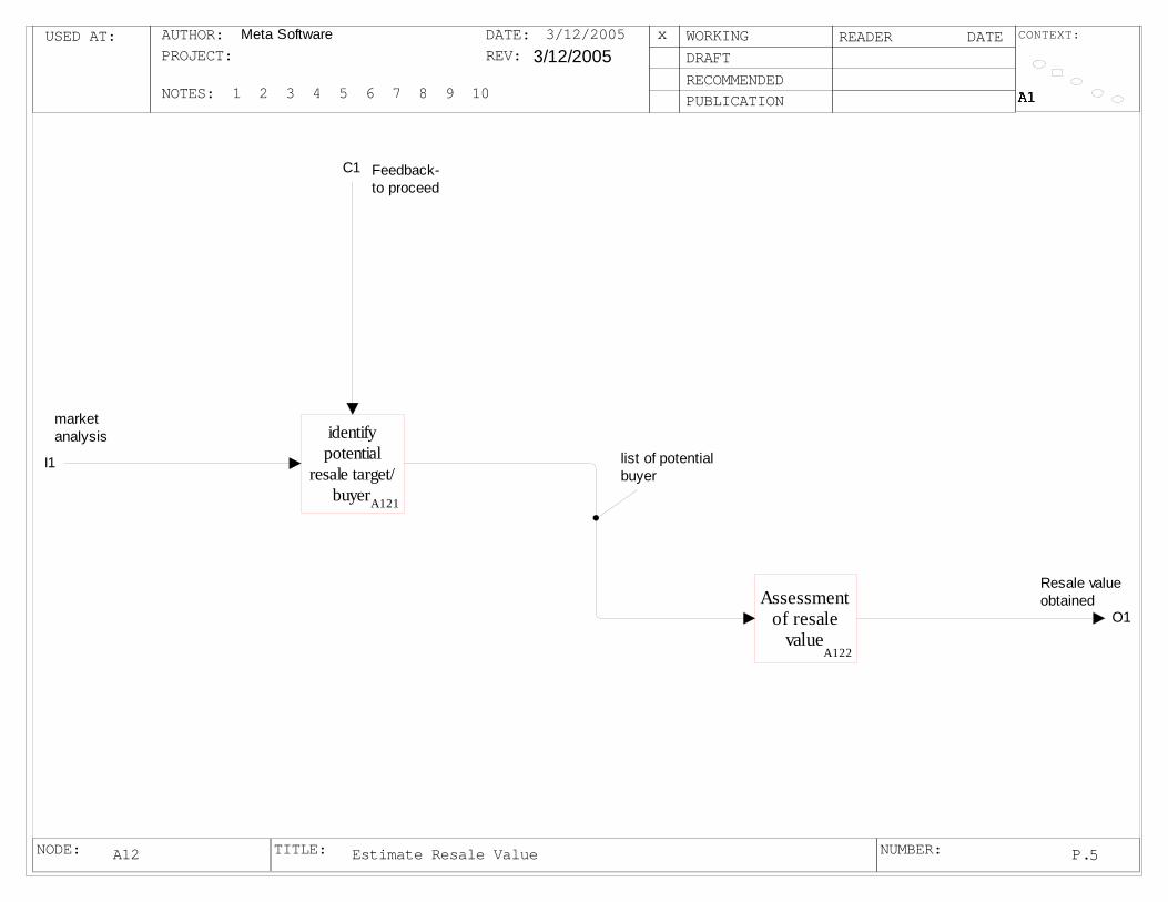
USED AT: CONTEXT:
NODE: TITLE: NUMBER:
AUTHOR:PROJECT:
NOTES: 1 2 3 4 5 6 7 8 9 10
DATE:REV:
WORKINGDRAFTRECOMMENDEDPUBLICATION
READER DATE
P.
Meta Software 3/12/2005
A1A1A1A1A1
5
x3/12/2005
Estimate Resale ValueA12
identify potential
resale target/buyerA121
Assessment of resale
valueA122
C1 Feedback-to proceed
list of potentialbuyer
I1
market analysis
O1
Resale valueobtained
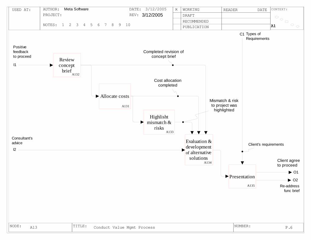
USED AT: CONTEXT:
NODE: TITLE: NUMBER:
AUTHOR:PROJECT:
NOTES: 1 2 3 4 5 6 7 8 9 10
DATE:REV:
WORKINGDRAFTRECOMMENDEDPUBLICATION
READER DATE
P.
Meta Software 3/12/2005
A1A1A1A1A1
6
x3/12/2005
Conduct Value Mgmt ProcessA13
O2Re-address
func brief
Review concept
briefA132
Evaluation & development of alternative
solutionsA134
Completed revision of concept brief
Allocate costs
A131
Highlisht mismatch &
risksA133
Cost allocationcompleted
Mismatch & riskto project was
highlighted
O1
Client agree to proceed
Presentation
A135
C1 Types of Requirements
Client's requirements
I1
Positive feedbackto proceed
I2
Consultant's advice

USED AT: CONTEXT:
NODE: TITLE: NUMBER:
AUTHOR:PROJECT:
NOTES: 1 2 3 4 5 6 7 8 9 10
DATE:REV:
WORKINGDRAFTRECOMMENDEDPUBLICATION
READER DATE
P.
Meta Software 3/12/2005
A1A1A1A1A1
7
x3/12/2005
Preparation of Outline ProposalA14
O1
Outline plancompleted
C2 Types of Requirements
C3Types of Procedures & Guidelines
Prepare Design
ProposalA142
Liaise with cost
planning consultant
A144
Initial planning permit
application preparationA146
Local Legislation
Statutory Req.
Authority & Planning requirements specified
Design proposal complete
outline plan complete
Review authorities
requirementsA143
Assess client's initial
feedbackA145
Ensure outline plan fulfils
project briefA141
C1Client agree to proceed
I1
Feedback-to proceed
Client's agreeto proceedClient's comment
to modified

USED AT: CONTEXT:
NODE: TITLE: NUMBER:
AUTHOR:PROJECT:
NOTES: 1 2 3 4 5 6 7 8 9 10
DATE:REV:
WORKINGDRAFTRECOMMENDEDPUBLICATION
READER DATE
P.
Meta Software 3/12/2005
A1A1A1A1A1
8
x3/12/2005
Prepare Preliminary EstimateA15
I1
Outline plancompleted
O1
Concept Approved
C1 Types of Procedures & Guidelines
Search solution for principles
A153 Select suitable
design/cost solution
combinationA154
Evaluatie choice of
alternativesA155
improve details &
cost optionsA156
Cost guide
best solution found
best combinationachieved
best alternatives selected
Eng. feasibility
stidies/ liaise with
engineersA152 preliminary
eng. design
Development of OPC
A151
probable cost range for projectobtained
O2Concept declined
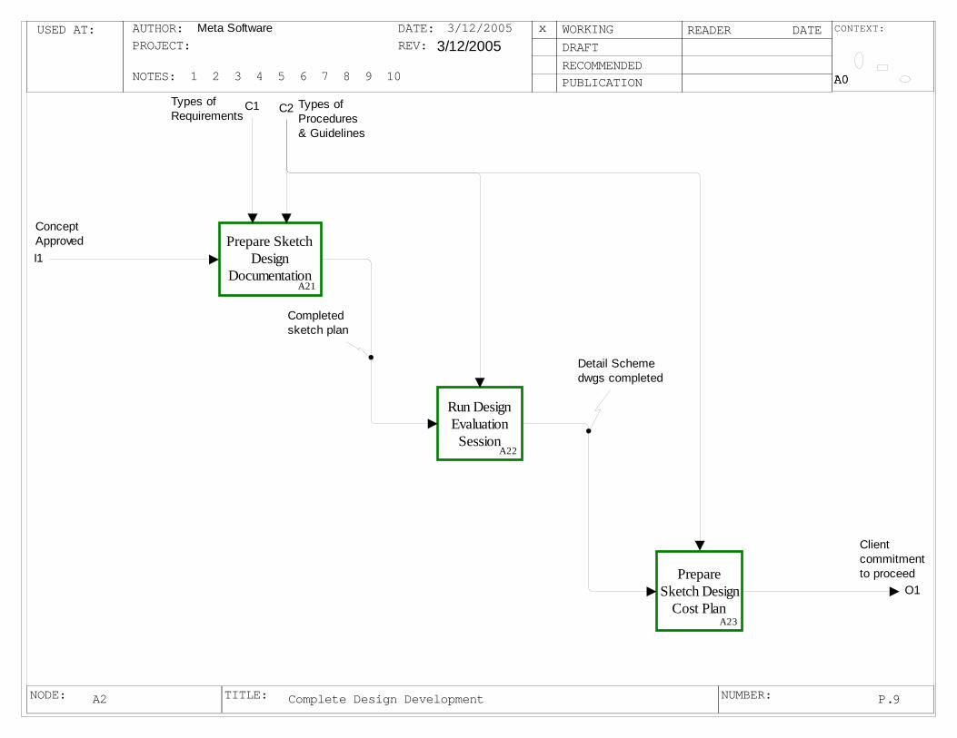
USED AT: CONTEXT:
NODE: TITLE: NUMBER:
AUTHOR:PROJECT:
NOTES: 1 2 3 4 5 6 7 8 9 10
DATE:REV:
WORKINGDRAFTRECOMMENDEDPUBLICATION
READER DATE
P.
Meta Software 3/12/2005
A0A0A0
9
x3/12/2005
Complete Design DevelopmentA2
I1
Concept Approved
O1
Client commitmentto proceed
C1Types of Requirements C2 Types of
Procedures & Guidelines
Prepare Sketch Design
DocumentationA21
Run Design Evaluation
SessionA22
Prepare Sketch Design
Cost PlanA23
Completed sketch plan
Detail Scheme dwgs completed
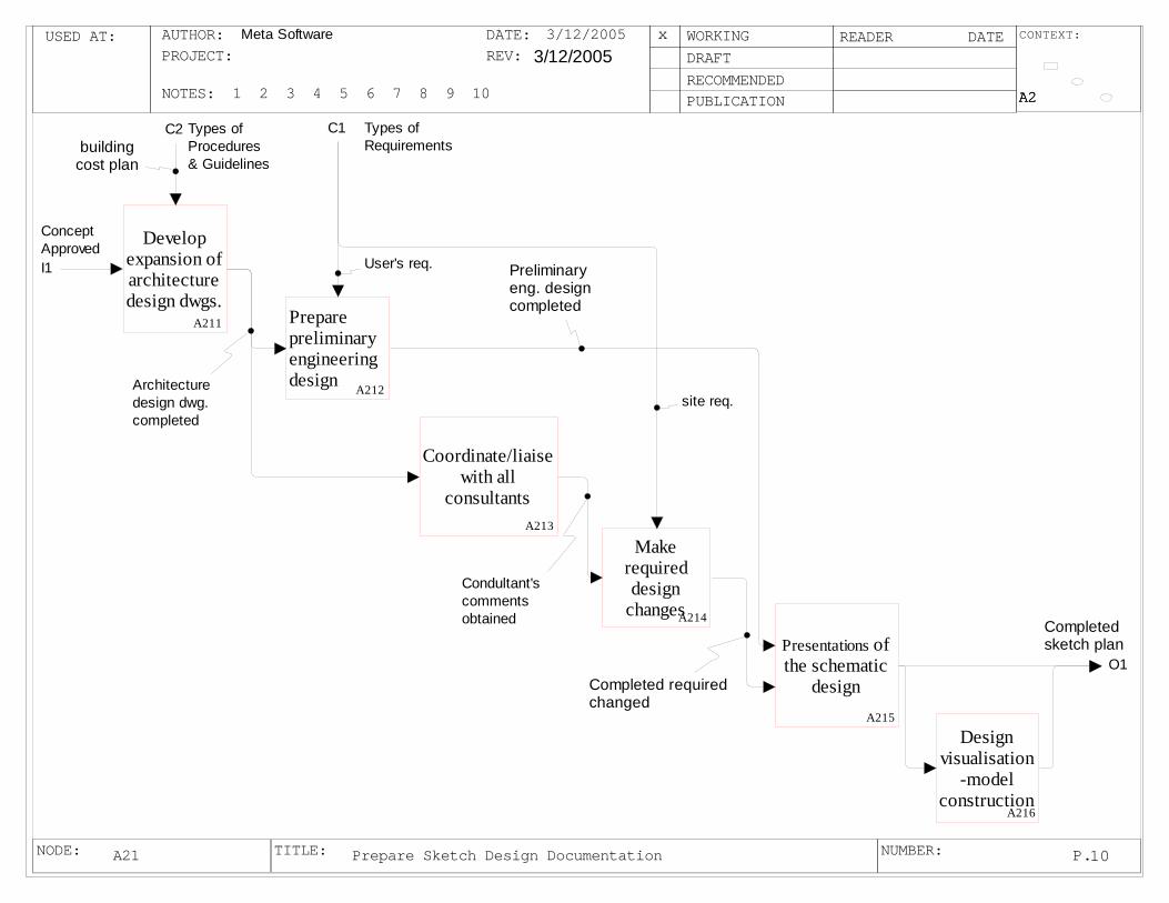
USED AT: CONTEXT:
NODE: TITLE: NUMBER:
AUTHOR:PROJECT:
NOTES: 1 2 3 4 5 6 7 8 9 10
DATE:REV:
WORKINGDRAFTRECOMMENDEDPUBLICATION
READER DATE
P.
Meta Software 3/12/2005
A2A2A2
10
x3/12/2005
Prepare Sketch Design DocumentationA21
I1
Concept Approved
C1 Types of Requirements
C2 Types of Procedures & Guidelines
O1
Completed sketch plan
Develop expansion of architecture design dwgs.
A211 Prepare preliminary engineering design A212
Make required design
changesA214
Presentations of the schematic
design A215
Design visualisation
-model construction
A216
building cost plan
User's req.
site req.
Completed requiredchanged
Preliminaryeng. designcompleted
Coordinate/liaise with all
consultantsA213
Architecture design dwg.completed
Condultant's comments obtained

USED AT: CONTEXT:
NODE: TITLE: NUMBER:
AUTHOR:PROJECT:
NOTES: 1 2 3 4 5 6 7 8 9 10
DATE:REV:
WORKINGDRAFTRECOMMENDEDPUBLICATION
READER DATE
P.
Meta Software 3/12/2005
A2A2A2
11
x3/12/2005
Run Design Evaluation SessionA22
I1
Completed sketch plan
C1Types of Procedures & Guidelines
O1
Detail Scheme dwgs completed
Integrate preliminary consultant's advice in design A221
Review authority/ council
requirementsA222
Apply for planning permit
A225
Design guideline
Legal and Statutorystatutory ptocedure
consensusachieved
Finalised design
documentationA224
changes complete
Gather feedbacksfrom all
authority and consultantsA223
Completed revision
Completed finalisation
Sumarised feedbacks
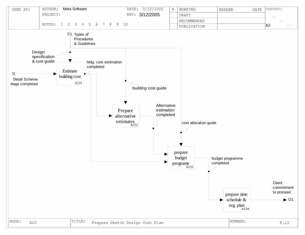
USED AT: CONTEXT:
NODE: TITLE: NUMBER:
AUTHOR:PROJECT:
NOTES: 1 2 3 4 5 6 7 8 9 10
DATE:REV:
WORKINGDRAFTRECOMMENDEDPUBLICATION
READER DATE
P.
Meta Software 3/12/2005
A2A2A2
12
x3/12/2005
Prepare Sketch Design Cost PlanA23
I1Detail Scheme
dwgs completed
C1 Types of Procedures & Guidelines
O1
Client commitmentto proceed
Estimate building cost
A231
Prepare alternative estimates
A232
prepare budget
programeA233
prepare time schedule & org. plan
A234
Design specification & cost guide
building cost guide
cost allocation guide
bldg. cost estimationcompleted
Alternative estimationcompleted
budget programmecompleted

USED AT: CONTEXT:
NODE: TITLE: NUMBER:
AUTHOR:PROJECT:
NOTES: 1 2 3 4 5 6 7 8 9 10
DATE:REV:
WORKINGDRAFTRECOMMENDEDPUBLICATION
READER DATE
P.
Meta Software 3/12/2005
A0A0A0
13
x3/12/2005
Complete DocumentationA3
I1
Client commitmentto proceed
O2Improve Communication
C1Types of Requirements
C2 Types of Procedures & Guidelines
Conduct detail design
managementA31
conduct cost
checkingA32
audit completion of
detail planA33
Documentationfor lodgementcompleted
Completed cost checking
O1Design process sucess
O3Improve Info. Flow
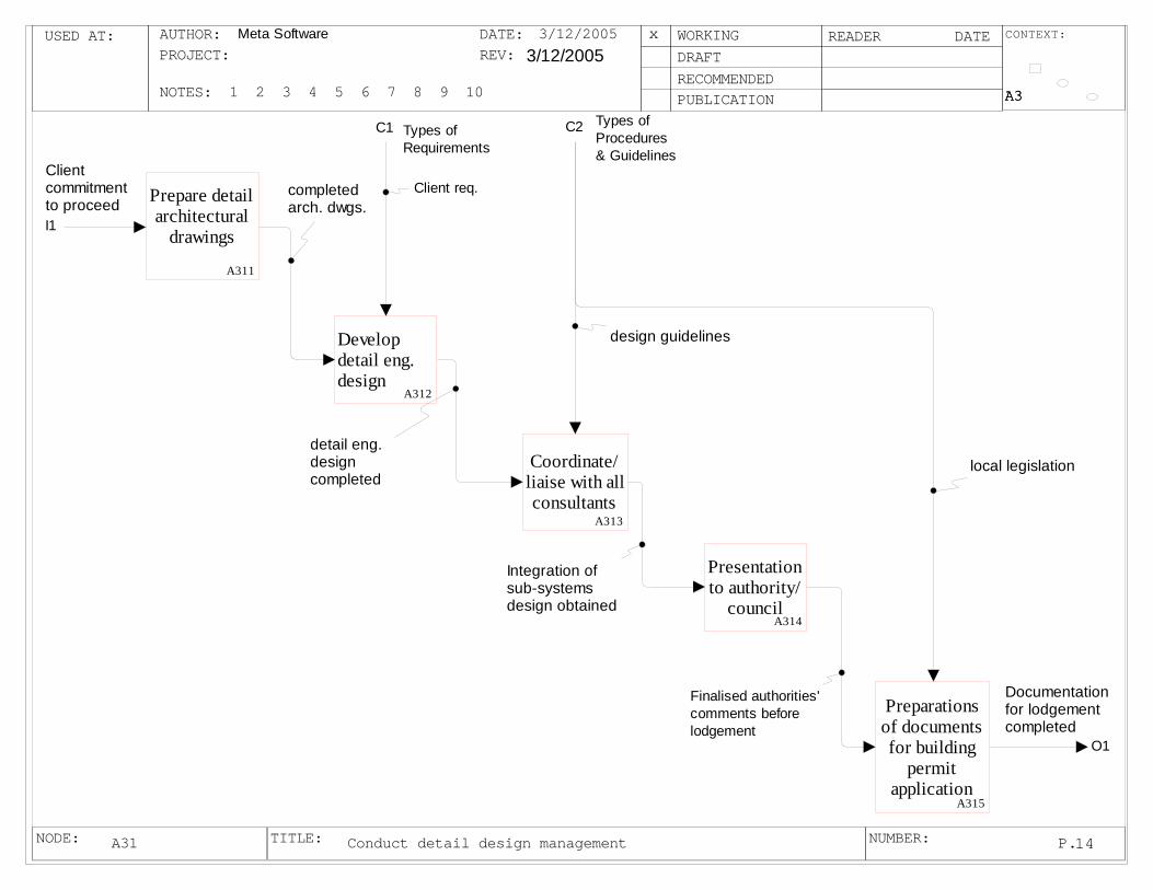
USED AT: CONTEXT:
NODE: TITLE: NUMBER:
AUTHOR:PROJECT:
NOTES: 1 2 3 4 5 6 7 8 9 10
DATE:REV:
WORKINGDRAFTRECOMMENDEDPUBLICATION
READER DATE
P.
Meta Software 3/12/2005
A3A3A3
14
x3/12/2005
Conduct detail design managementA31
I1
Client commitmentto proceed
C1 Types of Requirements
C2 Types of Procedures & Guidelines
O1
Documentationfor lodgementcompleted
Develop detail eng. design
A312
Coordinate/ liaise with allconsultants
A313
Presentation to authority/
councilA314
Preparations of documents for building
permit application
A315
Client req.
local legislation
design guidelines
Integration ofsub-systemsdesign obtained
detail eng. design completed
Prepare detail architectural
drawings
A311
completed arch. dwgs.
Finalised authorities'comments beforelodgement
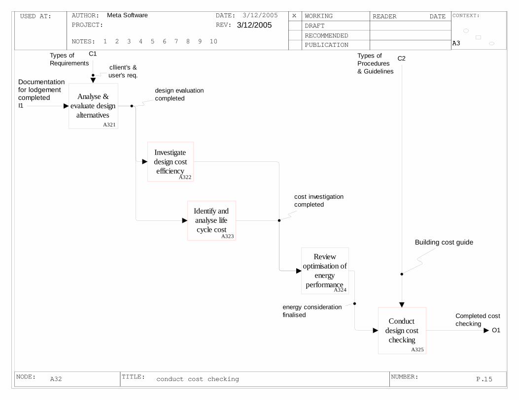
USED AT: CONTEXT:
NODE: TITLE: NUMBER:
AUTHOR:PROJECT:
NOTES: 1 2 3 4 5 6 7 8 9 10
DATE:REV:
WORKINGDRAFTRECOMMENDEDPUBLICATION
READER DATE
P.
Meta Software 3/12/2005
A3A3A3
15
x3/12/2005
conduct cost checkingA32
I1
Documentationfor lodgementcompleted
C1Types of Requirements
C2Types of Procedures & Guidelines
O1
Completed cost checking
Analyse & evaluate design
alternativesA321
Investigate design cost efficiency
A322
Review optimisation of
energy performance
A324
Conduct design cost checking
A325
cllient's & user's req.
Building cost guide
design evaluation completed
cost investigationcompleted
energy considerationfinalised
Identify and analyse life cycle cost
A323

USED AT: CONTEXT:
NODE: TITLE: NUMBER:
AUTHOR:PROJECT:
NOTES: 1 2 3 4 5 6 7 8 9 10
DATE:REV:
WORKINGDRAFTRECOMMENDEDPUBLICATION
READER DATE
P.
Meta Software 3/12/2005
A3A3A3
16
x3/12/2005
audit completion of detail planA33
I2
Completed cost checking
C1 Types of Procedures & Guidelines
O2Improve Communication
Lodgement for building
permitA331
Rationalisation & integration of
sub-systems desgin
A332
To consider Occupational
health & safety- Safe
designA333
Conduct risk management
A334
I1
Documentationfor lodgementcompleted
building permitapproved
Safe designobtained
sub-system integration completed
O1Design process sucess
O3Improve Info. Flow
Advisory Note(AN13.01.103)
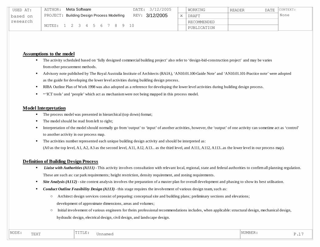
USED AT: CONTEXT:
NODE: TITLE: NUMBER:
AUTHOR:PROJECT:
NOTES: 1 2 3 4 5 6 7 8 9 10
DATE:REV:
WORKINGDRAFTRECOMMENDEDPUBLICATION
READER DATE
P.
Meta Software Building Design Process Modelling 3/12/2005 None
17
xbased on research
3/12/2005
UnnamedTEXT
Assumptions to the modelThe activity scheduled based on ‘fully designed commercial building project’ also refer to ‘design-bid-construction project' and may be varies
from other procurement methods.
Advisory note published by The Royal Australia Institute of Architects (RAIA), ‘AN10.01.100-Guide Note’ and ‘AN10.01.101-Practice note’ were adopted
as the guide for developing the lower level activities during building design process.
RIBA Outline Plan of Work 1998 was also adopted as a reference for developing the lower level activities during building design process.
**‘ICT tools’ and ‘people’ which act as mechanism were not being mapped in this process model.
Model InterpretationThe process model was presented in hierarchical (top down) format;
The model should be read from left to right;
Interpretation of the model should normally go from ‘output’ to ‘input’ of another activities, however, the ‘output’ of one activity can sometime act as ‘control’
to another activity in our process map.
The activities number represented each unique building design activity and should be interpreted as:
(A0 as the top level, A1, A2, A3 as the second level, A11, A12, A13... as the third level, and A111, A112, A113...as the lower level in our process map).
Definition of Building Design Process Liaise with Authorities (A111) - This activity involves consultation with relevant local, regional, state and federal authorities to confirm all planning regulation.
These are such as: car park requirements; height restriction, density requirement, and zoning requirements.
Site Analysis (A112) - site context analysis involves the preparation of a master plan for overall development and phasing to show its best utilisation.
Conduct Outline Feasibility Design (A113) - this stage requires the involvement of various design team, such as:
o Architect design services consist of preparing: conceptual site and building plans; preliminary sections and elevations;
development of approximate dimensions, areas and volumes;o Initial involvement of various engineers for theirs professional recommendations includes, when applicable: structural design, mechanical design,
hydraulic design, electrical design, civil design, and landscape design.

USED AT: CONTEXT:
NODE: TITLE: NUMBER:
AUTHOR:PROJECT:
NOTES: 1 2 3 4 5 6 7 8 9 10
DATE:REV:
WORKINGDRAFTRECOMMENDEDPUBLICATION
READER DATE
P.
Meta Software 3/12/2005 None
18
x3/12/2005
UnnamedTEXT
Definition to Building Design Process (continue)Assessment of Consultant’ recommendations (A114) - to gather, analyse and run assessment of recommendations from all trade consultants.
Conduct environmental analysis (A115) - to consider the environmental strengths and weaknesses of the proposed development, and scan the environment
for opportunities on the selected site;
Seek client’s initial feedback (A116) - presentation of the Clients to review recommendations from previous stages for feedback.
Identify potential resale target/buyer (A121) - to identify potential buyer and to find out the target group;
Assessment of resale value (A122) - to assess resale value of the building (final product), may involve market analysis;
Review concept brief (A131) - to review concept brief obtained from previous stages and to confirm client’s objectives for the project. These are such as:
the initial plans, elevations, sections, specification and cost plan of the proposed facility. It is important to fully understand the concept brief, particularly
the functional space requirements and adjacency prior to the allocation of cost for each trade.
Allocate costs (A132) - this stage involves the allocation of costs from the cost plan to functions and spaces.
Highlight mismatched and risks (A133) - to identify and to highlight any mismatched between cost allocation to functions and spaces. To run risk
assessment for each design option.
Evaluation and development of alternative solutions (A134) - evaluation of design alternative and brainstorming for better solutions.
Presentations (A135) - presentations of preferred solution to clients or client’s representative.
Ensure outline plan fulfils project brief (A141) - to ensure that the outline design drawings encompass the requirements of the brief prepared earlier.
Prepare design proposal (A142) - producing a sketch drawings based on the information obtained from various stakeholders includes engineers, cost consultant,
authorities and consultants.
Review authorities’ requirements (A143) - to review authorities’ requirement to ensure that the outline schematic design meets all regulatory’ requirements.
Liaise with cost planning consultant (A144) - liaise with cost planning consultant to prepare preliminary costing for the project, for comparison with target budgets.
Assess client’s initial feedbacks (A145) - Assess client’s initial feedbacks from stage A116.
Initial Planning Permit Application Preparation (A146) - prepare initial scheme design drawings, based on authorities’ comments, consultants’ recommendations
and client’s feedback.

USED AT: CONTEXT:
NODE: TITLE: NUMBER:
AUTHOR:PROJECT:
NOTES: 1 2 3 4 5 6 7 8 9 10
DATE:REV:
WORKINGDRAFTRECOMMENDEDPUBLICATION
READER DATE
P.
Meta Software 3/12/2005 None
19
x3/12/2005
UnnamedTEXT
Definition of Building Design Process (continue)Development of Opinion of Probable Cost and Program (OPC) (A151) - liaison with cost consultant to develop opinion regarding: probable construction cost range
for the project.
Engineering cost studies/ liaise with engineers (A152) - undertake cost studies to determine appropriate engineering solutions.
Search for principal solutions (A153) - Assess and decide upon appropriate design/cost solutions to principal elements of the project.
Select suitable design/cost solution combination (A154) - Assemble and choose the most appropriate combinations of design/cost solutions.
Evaluations of choices of alternatives (A155) - prepare costing to appropriate level of detail, and compare with budget targets.
Improve details and cost options (A156) - to improve the details and cost options within the alternative design solutions considered; update costing and budget
comparisons; report to client for decision-making.
Develop expansion of architecture design drawings (A211) - the development and expansion of architectural schematic design documents, revised in accordance
with client’s instructions and as necessitated by any revision to estimate cost, including: plans at each level, elevations, sections and other details or schedules
sufficient to fully explain the design (AN10.01.101.4.02).
Prepare preliminary engineering design (A212) - it consist of the continued development of the various engineering design as done in outline feasibility
design stage A113.
Coordinate/liaise with all consultants (A213) - coordinate and integrate the design work with all consultants.
Make required design changes (A214) - make required changes based on consultants’ recommendations.
Presentations of the schematic design (A215) - presentation of the schematic design to all relevant stakeholders, such as: client, building owner, staff committee,
user groups, boards of directors, financier, owner’s consultants for comment (A10.01.101.4.11)
Design Visualisation - Model Construction (A216) - model construction (if necessary); physical and/or virtual models of the proposed building, showing the
interrelationship of the spatial layouts, in 2D and 3D formats, are very useful for many clients; they are also an effective way of depicting constructional methods;
Integrate preliminary consultant’s advise in design (A221) - all design team members have to work together to make final decisions regarding design aspects,
materials, finishes, services, and various other matters.
Review authorities/council requirements (A222) - review all relevant planning and authorities’ requirements, are calculations and car parking (A10.01.100-clauseB8).
Gather feedback from all authorities and consultants (A223) - feedback from all authorities and consultant is consolidated into necessary design change proposals.
Finalised design documents (A224) - to finalised and make required design changes base on authority’s’/consultants’ feedback.

USED AT: CONTEXT:
NODE: TITLE: NUMBER:
AUTHOR:PROJECT:
NOTES: 1 2 3 4 5 6 7 8 9 10
DATE:REV:
WORKINGDRAFTRECOMMENDEDPUBLICATION
READER DATE
P.
Meta Software 3/12/2005 None
20
x3/12/2005
UnnamedTEXT
Definition of Building Design Process (continue)Apply for planning permit (A225) - lodgement of documents by the architect on behalf of the client to the relevant authorities for planning approval (AN10.01.101.4.12).
Estimating building cost (A231) - cost consultant prepares more detailed cost plan for the project, based upon development of outline design, for comparison with target
cost budgets.
Prepare alternative estimates (A232) - for difference construction methods, materials, engineering systems to ensure that best design solutions are obtained within
the established budget.
Prepare budget program (A233) - show how the total cost is allocated among the various part of the project.
Prepare time schedule & organization plan (A234) - prepare outline time schedule and organization plan to give the client an indication as to when building work
will commence on site and how long it will take to complete.
Prepare detailed architectural drawings (A311) - to precede on the basis of the scheme design drawings and to develop in a more finished form, including more
detailed drawings and specifications and incorporating the specialist contributions of the various consultants. The documents include as stated in AN10.01.101.5.02 are: o Working drawings for tendering and construction
o Specification comprising detailed written descriptions of the content of the project materials and workmanship.
Develop detail engineering design (A312) - develop engineering documentation, setting forth in detail the various engineering construction requirements of the
project for tendering and construction purposes, consisting of the preparation of: final engineering calculations; drawings; specifications and schedules.
Coordinate/liaise with all consultants (A313) - coordinate and integrate sub consultant design with the architectural drawings and specifications (A10.01.100).
Presentation to authority/council (A314) - final presentation to local authority/council before lodgement to ensure all design complies with building regulations.
Preparations of documents for building permit application (A315) -prepare documentation including dimensioned plans, sections and elevations to adequately
describe the design for the purpose of obtaining approval to construct (A10.01.100).
Analysis & evaluate design alternatives (A321) - interaction between all project professionals and facility manager (if appointed) to ensure that the building
provides its users with basic elements that maintain the necessary comfort which allows them to carry out their jobs;
Investigate design cost efficiency (A322) - to ensure cost efficiency of the proposed building design, to consider and identify which elements of the building require
the least maintenance, and incur the fewest breakdowns and repairs. Also, those with the most maintenance and repair requirements.

USED AT: CONTEXT:
NODE: TITLE: NUMBER:
AUTHOR:PROJECT:
NOTES: 1 2 3 4 5 6 7 8 9 10
DATE:REV:
WORKINGDRAFTRECOMMENDEDPUBLICATION
READER DATE
P.
Meta Software 3/12/2005 None
21
x3/12/2005
UnnamedTEXT
Definition of Building Design Process (continue)Identify and analyse life cycle cost (A323) - assess the life cycle cost of the building; in short-term; medium-term; and long-term.
Review optimization of energy performance (A324) - review energy performance for proposed design, to consider which elements within the building are the most
energy in-efficient;
Conduct design cost check (A325) - cost consultant to review the cost plan after all stages and to carry out cost studies and cost checks as the design team finally
shape their details. Lodgement for building permit (A331) - submit application to the relevant authority for building approval
Rationalise & integrate sub-systems designs (A332) - rationalize and integrate all design sub-systems to make sure they have no conflicts.
To consider Occupational Health and Safety- Safe Design (A333) - to ensure that the proposed design can be safely built, used, maintained, and demolished by
those who construct and use it (AN13.01.103).
Conduct risk management (A334) - to assess and balance the contingencies of risk with their specific contractual, financial, operational and organizational
requirements by transferring through the combination of insurance, risk financing, and contract indemnification provisions.

216
APPENDIX-B
Invitation Letter
12th Oct, 2004
Casta YL Choong,
RMIT University,
GPO Box 2476V
Melbourne VIC 3001
Australia
Dear Sir/ Madam,
Re: Development of a best practice model for the building design process on large-
scale commercial projects: A Delphi Study.
My name is Casta YL Choong. I am undertaking a PhD research programme with School of
Property, Construction and Project Management at RMIT University. The tittle of my
research is “A best practice model for the building design process on large-scale commercial
project – a Delphi survey”. I am writing to invite your participation in a Delphi study on the
issue of Information and Communication technology (ICT) during the building design
process. This study will form the basis of my PhD research supervised by Associate Professor
Peter Stewart and Mr. Geoff Outhred from School of Property, Construction and Project
Management at RMIT University.
The aim and objectives of this study are:-
To better understand how Information and Communication Technology (ICT) is
currently being implemented during building design process on large scale office
building projects.
School of Property, Construction and Project Management
217
To investigate and to propose a best practice model for ICT use during the building
design process using IDEF0 modelling language.
To test and improve the best practice model using a Delphi panel.
To revise the best practice model based on the likely developments in ICT over 5
years. This revised model will also be tested using a Delphi panel.
The best practice models developed as part of this research will enable organisations to adapt
their current approach towards a best practice model and then to plan improvements to
account for ICT innovations in the coming 5 years.
A panel of 9 experts will be surveyed using Delphi approach. You have been selected and
invited to participate in this study based on your understanding of the research area. Your
experiences, insights, and opinions concerning the issues being explored will provide a
valuable contribution to the best practice model being developed as part of this research. The
data collected as part of the Delphi process will seek to identify areas of consensus and
disagreement among the panellists and this will help refine the best practice model.
In this first stage we expect there to be five survey rounds. The study is scheduled to be
completed in two to three months time. The amount of time necessary for completion of each
round will vary with each panellist, but should range from approximately half to one hour for
each round. The summary result of each stage will be analysed and made available to you for
your reconsideration in the next stage. A final report will be presented to you at the
conclusion of this research.
All participants will retain anonymity, as the Delphi rounds will be conducted by mail and
each participant will be assigned a unique code which will only be known by the researcher
and supervisor. Participation in this research is voluntary and anyone may refuse to answer
any question at any time during the research and any unprocessed data may also be
withdrawn.
We hope you are willing to participate in this research study and your acceptance will be
confirmed once you complete the enclosed ‘Consent Form’. The completed consent form
should be mailed/fax to me at the address supplied below.
Thank you for your consideration and please do not hesitate to contact me or my supervisor
218
on (Tel: 613- 9925 3453 or email: [email protected]) should you required further
information.
Regards,
Casta YL Choong,
PhD Candidate,
School of Property, Construction and Project Management, Building 8, Level 8, Room 74 (8.8.74) RMIT University
Swanston Street
Melbourne
Email: [email protected]
Tel: (613) 9925 9659
Fax: (613) 9925 1939
Mobile: 0413 091 122

219
CONSENT FORM
RMIT HUMAN RESEARCH ETHICS COMMITTEE Prescribed Consent Form for Persons Participating In Research Projects Involving Interviews,
Questionnaires, Focus Groups or Disclosure of Personal Information
PORTFOLIO OF Design and Social Context
SCHOOL/CENTRE OF Property, Construction and Project Management
Name of participant:
Project Title: A Best Practice Model for Building Design Process on large-scale Commercial
Projects – A Delphi Study
Name(s) of investigators: (1) CASTA YILI CHOONG
(2) Phone: 0413 091 122
1. I have received a statement explaining the interview/questionnaire involved in this project.
2. I consent to participate in the above project, the particulars of which - including details of the interviews or
questionnaires - have been explained to me.
3. I authorise the investigator or his or her assistant to interview me or administer a questionnaire.
4. I give my permission to be audio taped Yes No
5. I give my permission for my name or identity to be used Yes No
6. I acknowledge that:
(a) Having read the Plain Language Statement, I agree to the general purpose, methods and demands of the
study.
(b) I have been informed that I am free to withdraw from the project at any time and to withdraw any
unprocessed data previously supplied.
(c) The project is for the purpose of research and/or teaching. It may not be of direct benefit to me.
(d) The privacy of the information I provide will be safeguarded. However should information of a private
nature need to be disclosed for moral, clinical or legal reasons, I will be given an opportunity to negotiate
the terms of this disclosure.
(e) The security of the research data is assured during and after completion of the study. The data collected
during the study may be published, and a report of the project outcomes will be provided
to_____________(researcher to specify). Any information which may be used to identify me will not be
used unless I have given my permission (see point 5).
Participant’s Consent
Name: Date: (Participant)
Name: Date: (Witness to signature)
Where participant is under 18 years of age:
I consent to the participation of ____________________________________ in the above project.
Signature: (1) (2) Date: (Signatures of parents or guardians)

220
Name: Date: (Witness to signature)
Participants should be given a photocopy of this consent form after it has been signed.
Any complaints about your participation in this project may be directed to the Secretary, RMIT Human Research Ethics
Committee, University Secretariat, RMIT, GPO Box 2476V, Melbourne, 3001. The telephone number is (03) 9925
1745.
Details of the complaints procedure are available from : www.rmit.edu.au/council/hrec

221
APPENDIX-C DELPHI ROUND ONE SURVEY PACK
Email Notice to begin Round One
Dear [Participant],
Thank you for agreeing to participate and share your knowledge, expertise with us in the
Delphi study to develop a best practice model for the building design process on large-scale
commercial project. Since contacting everyone, it has become obvious that there are a number
of issues to be included, and it is possible that the number of rounds may increase as a
consequence. I hope this will not cause you any difficulty, and I still plan to complete all
rounds well before Christmas. I have planned for a maximum of 5 rounds and there are
scheduled as follows:
October 12 – 17: First round response to questionnaires
October 26 – 31: Second round response to questionnaires
November 9 – 14: Third round response to questionnaires
November 23 – 28: Forth round response to questionnaires
December 7 – 12: Final round response to questionnaires
I have to admit that the schedule is compressed but we are hoping it will reduce the time you
have to commit to the Delphi rounds. A notice to begin Round 1 survey will be sending out
soon comprises instruction to answer Round 1 questions, a web link for the online
questionnaire, and an assign code for each of you. Once again thank you for your
participation.
Regards,
Casta
222
Instruction to Begin Delphi Study Round 1
(October 12 – 17, 2004)
Dear [Participant],
Thank you for agreeing to participate and share your knowledge, expertise with us in the
Delphi study to develop a best practice model for the building design process on large-scale
commercial project. Since contacting everyone, it has become obvious that there are a number
of issues to be included, and it is possible that the number of rounds may increase as a
consequence. I hope this will not cause you any difficulty, and I still plan to complete all
rounds well before Christmas. I have planned for a maximum of 5 rounds and there are
scheduled as follows:
October 12 – 17: First round response to questionnaires
October 18 – 25: I will review and analyse the responses
October 26 – 31: Second round response to questionnaires
November 1 – 8: I will review and analyse the responses
November 9 – 14: Third round response to questionnaires
November 15 – 22: I will review and analyse the responses
November 23 – 28: Forth round response to questionnaires
November 29 – December 6: I will review and analyse the responses
December 7 – 12: Final round response to questionnaires
December 13 – 19: I will review and analyse the responses
I have to admit that the schedule is compressed but we are hoping it will reduce the time you
have to commit to the Delphi rounds. The following section will provide a brief description
on how to interpret the research model.
Please Note: I should make you aware of the research topic, to enable you to answer question
more comprehensively. I have therefore described below the IDEF0 model. This is for your
interest and information only, and you do not need to be fully aware of this research technique
in order to answer the questions. So please do not be daunted by the research system.

223
How to interpret the research model (which use the IDEF0 modelling language)
The graphical language of IDEF0 contains two basic constructs: boxes representing activities
and arrow segments representing ICOM entities (see figure.1). ICOMs refer to: Inputs
(information or physical things), Control (rules or policies that guide how the activities are
performed), Output (information or physical things), and Mechanisms (resources used to
perform the activities).
Figure 1 Arrow positions and roles
IDEF0 models are developed through a process of top down structured decomposition. The
fundamental building block of an IDEF0 model is the activity, which may be decomposed
into subactivities, sub-subactivities, and so on. Activities are decomposed into subactivities
(children), which in turn, are decomposed into sub-subactivities (grandchildren), and so on.
Activity numbers show the decomposition. Activity A12 is the child of activity A1. Activity
A452 is a child of A45 and so on. A list of activities and children is called an “activity tree”
(see figure 2).
Figure 2 IDEF0 Parent to Child diagram Numbering (Activity tree)

224
For the purpose of this research project we will be focusing on the pre- construction stage of
building design process which encompasses the ‘outline design’ through to ‘detail design’
stage.
Figure 3 shows the top-level IDEF0 context diagram developed to represent the scope of this
process. You will find a bracket on the ‘people’ arrow which represents no further
decomposition for this entity. In this study, the context diagram was decomposed into three
main sub-functions, namely: ‘complete outline design’; ‘complete scheme design’; and
‘complete detail design’. Figure 4 is an IDEF0 diagram which encodes the ‘building design
process’. Figure 5 shows a further level of decomposition at the level of the ‘complete outline
design’ sub-function. In total, four levels of functional decomposition were prepared for this
study for your review and comment. The model will be modified based on the comments from
yourself and the other Delphi panel members.
BDM Process
A0
FeasibilityStudies Improve Communication
ICT Tools
People
Types of Requirements
Types of Procedures & Guidelines
Notes:
*Only ICT Tools will be focus for the purpose of this research.
*ICT Infrastructure covers:Internet, Intranet, Extranet, Information Exchange Standard,Authentication, Digital Signature,and Cryptography.
Design process sucess
Improve Information Flow
Figure 3 Top Level Diagram for Building Design Management Process (A-0 diagram)

225
Complete Ouline Design
A1
Complete Scheme Design
A2
Complete Detail Design
A3
I1
FeasibilityStudies
O2 Improve Communication
M1
ICT Tools
Concept Approved
Client commitmentto proceed
C1
Types of Requirements
C2
Types of Procedures & Guidelines
O1 Design process sucess
O3 Improve Information Flow
Figure 4 IDEF0 A0 Diagram for Building Design management Process
I1
FeasibilityStudies
O1
Concept Approved
M1
ICT Tools
Prepare Functional
BriefA11
Conduct Value Mgmt
ProcessA12
Prepare Concept Design
A13
Prepare Cost
PlanningA14
complete Valueprocess
Func Briefcompleted
Re-addressfunc brief
C1Types of Requirements
C2Types of Procedures & Guidelines
Outline plancompleted
ICT Infrastructure
ICt for Communication
ICT for Info. Mgt.
ICT Infrastructure
ICt for Communication
ICT for Info. Mgt.ICT Infrastructure
ICt for CommunicationICT for Info. Mgt.
ICT Infrastructure
ICt for CommunicationICT for Info. Mgt.
Func Briefcompleted
concept declined
Figure 5 IDEF0 A1 Diagram for Complete Outline Design
226
ROUND 1 of the Delphi questionnaires has three sections: (Note: Please print out this section and read in conjunction with the Internet Survey)
Section A:
We will begin by collecting some demographic information from you and the other
participants.
Section B:
This section will ask you to assess the extent to which you believe ICT tools are being used
during each of the lower level activities. You will be asked to rate the current usage of these
ICT tools and then the usage level you forecast in 5 years time.
We are not expecting you to be an expert user of each of these tools, as we are just seeking
your expert opinion on how these tools have and will be adopted by the building design
industry for the specific activities listed.
A five-point Likert-like rating scale will be used to determine the extent of use for each tool to
each activity. The categories are:
• (5) Essential – if you believe these tools allow project participants to perform their
work they can never done before;
• (4) Helpful – if you believe these tools have significantly decrease effort and make
things much more efficient and better quality;
• (3) Fairly useful – if you believe these tools are useful in performing job;
• (2) Not used – if you are not currently using these tools and interesting on using it in
future;
• (1) Un-necessary – if you have no interest in these tools and not desire to use it in the
future.
Section C:
In section C, each panellist is given an opportunity to include any lower level activities as
well as the list of lowest level activities during building design process that you feel we have
left out. For example, if you believe we have left out a lowest activities in lower-activity “A14
– Prepare Cost Planning” please add in with a code as” A145 – activity name (if the lowest
level activities happen after A144). Or if the activities happen earlier straight after activities
code A141, please put your suggested activity code as: A142 and we will move the original

227
activity to later stage with new code.
We would also like you to add in any sub-activity that you believe we have missed out in the
space provide towards the end of Section C.
The web questionnaire is now available for Round 1 and your response is requested by
October 17, 2004. You may access the Round 1 questionnaires at:
http://survey.tce.rmit.edu.au
We have assigned you a user ID for this study and it is: ___________
Please register yourself with your email address and chosen password before proceed to the
Delphi survey Round 1 survey.
Please do not hesitate to contact the researcher at [email protected] or mobile:
0413091122, should you require further information. Once again, thank you for your time and
your contribution to this research.
Regards,
Casta YL Choong
PhD Candidate,
School of Property, Construction and Project Management, Building 8, Level 8, Room 74 (8.8.74) RMIT University
Swanston Street
Melbourne
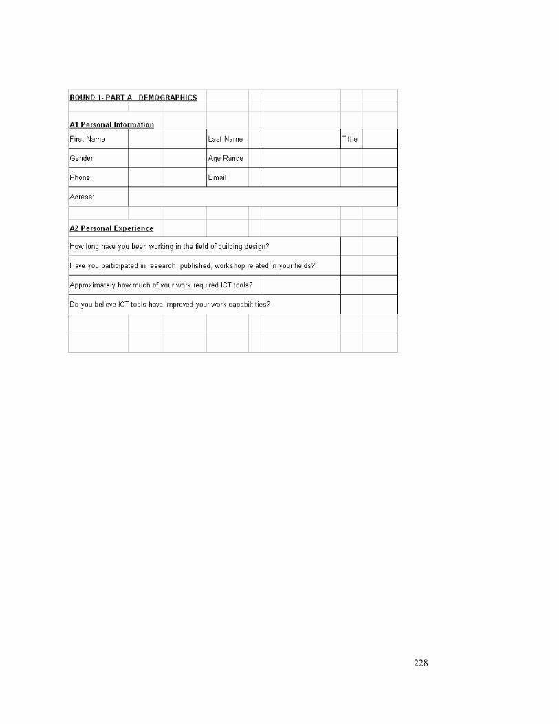
228
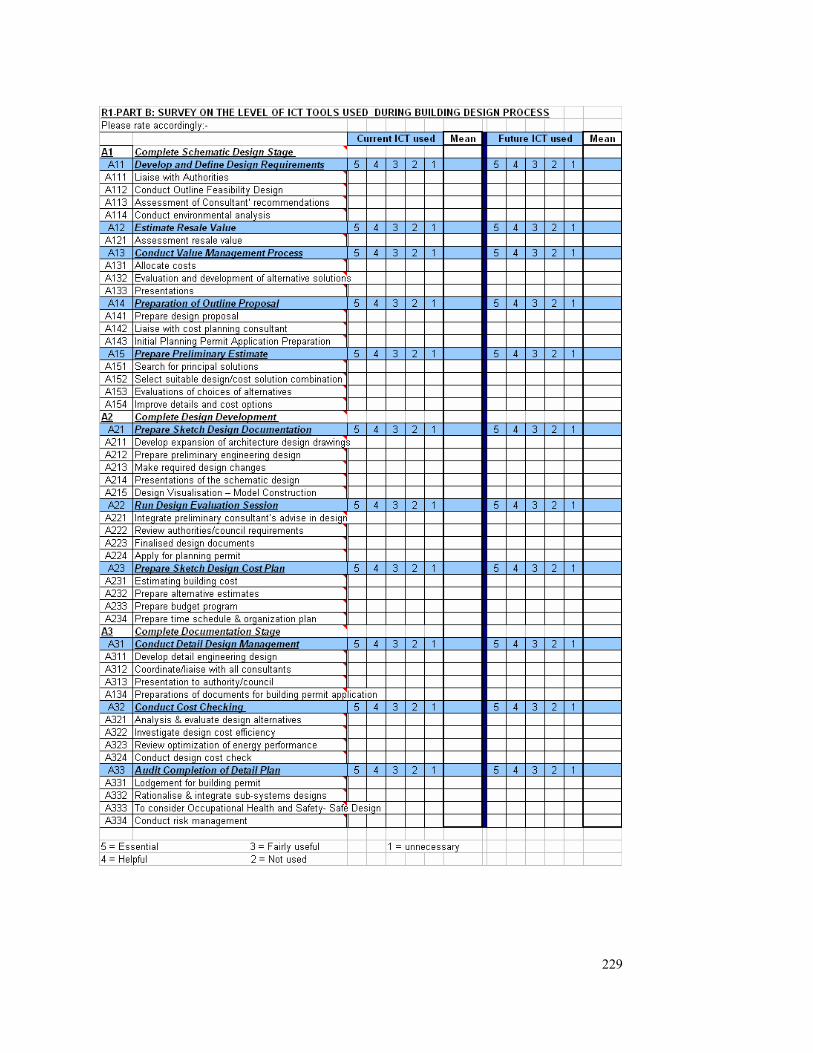
229
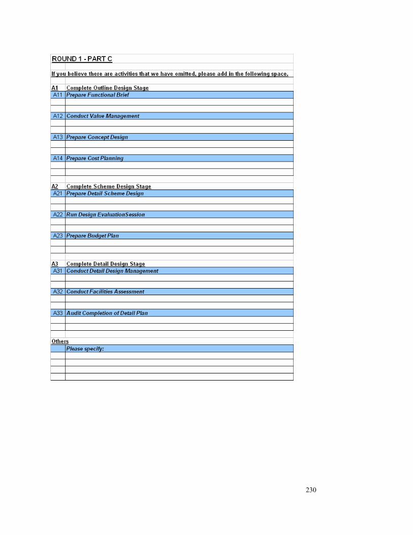
230

231
APPENDIX-D DELPHI ROUND TWO SURVEY PACK
Email Notice to begin Round Two
Dear Delphi panel member,
Please confirm receipt of this message.
Thank you very much for your responses to round 1 survey. After many days of reviewing
your feedback and refining the questions for Round 2, we are now ready to commence the
next round.
You will find two documents attached to this email, firstly the “Instructions for Round 2” in
word document format and the “Round 2 Survey Questions” in Excel format. Comments and
suggestions from the first round survey have encouraged me to changes the Round 2
questionnaire from web-based to Excel format.
Brief descriptions of all activities and all ICT tools have been included with the Round 2
Questions to ensure you understand the context for each question.
Obviously the Round 2 survey is later than originally scheduled and so we hope that you will
be able to respond to this round fairly quickly so that we can still finish by Christmas.
We hope you can submit responses via email attachment for Round 2 survey by 7th November
2004 (Sun), but if that is not possible could you email or call me to let me know the date you
expect to return the survey.
Once again, thank you for your contribution to the research. I would like to say that your
knowledge and patience has greatly helped the progress of this research.
Regards,
Casta

232
Instruction to begin Round 2 Delphi Survey (Note: Please print out this section and read in conjunction with the attached survey question in excel format)
Dear Delphi Panel members,
Once again we would like to remind all participants that we are not expecting you to be an
expert user of each of these tools, we are just seeking your expert opinion on how these tools
have and will be adopted by the building industry. The following section provides a brief
description of the Round 2 questionnaire.
Section A
This section is a summary of those additional lower level activities that you have suggested in
Round 1 Section 3. All of these activities have been categorised and you are required to rate
them using the same procedure and scale used for Round 1. The five point Likert-like rating
scale used in the last Round was as follows:-
• (5) Essential – if you believe these tools allow project participants to perform work
that was not possible before;
• (4) Helpful – if you believe these tools have significantly decrease effort and made
things much more efficient and of better quality;
• (3) Fairly useful – if you believe these tools are useful in performing job;
• (2) Not used – if you are not currently using these tools, they could be used and you
have interest on using it in future;
• (1) Un-necessary – if you have no interest in these tools and they are not needed to be
used in the future.
Section B
In section B, we would like to know what kinds of ICT tools you are using and the level of
usage for each of those activities. There are three ICT categories: ICT Infrastructure; ICT for
Communication; and ICT for Information Management.
We would like you to first give an overall rating (level of usage of each tool to the building
design process) for each of these tools to those activities listed. Then, you are asked to rate the
individual tools to each activities accordingly.

233
You may leave the boxes blank if you believe they have the same rating to the “overall rating”
you have rated earlier, or if you believe they have differ rating, please rate accordingly.
Section C
In Section C, you are welcome to add in tools that you believe we have left out in the section.
Please fill in the activities number which you believe the tools are applied to.
Finally, we would appreciate some comments on how we could improve the process for the
next Round.
Please submit responses for Round 2 survey by 7th November 2004 (Sunday) via email
attachment , and please do not hesitate to contact me at [email protected] or on
my mobile: 0413091122, should you require further information. Once again, thank you for
your time and your contribution to this research.
Regards,
Casta YL Choong
PhD Candidate,
School of Property, Construction and Project Management, Building 8, Level 8, Room 74 (8.8.74) RMIT University
Swanston Street
Melbourne
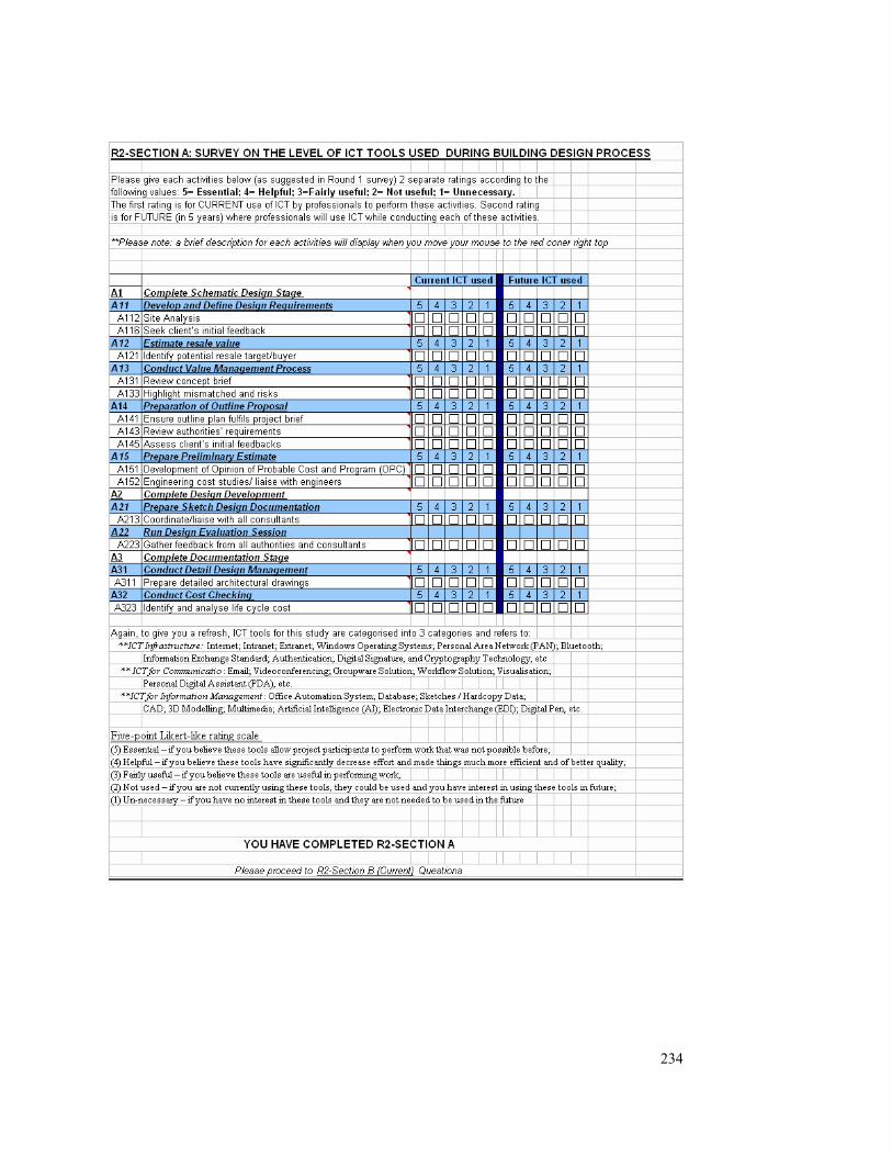
234
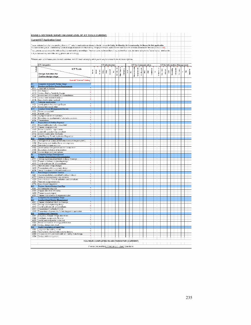
235

236

237

238
APPENDIX-E DELPHI ROUND THREE SURVEY PACK
Email Notice to begin Round Three
Dear Delphi panel member,
Thank you very much for your responses to round 2 survey. This is the third round. Once
again, we have spent days reviewing your feedback and comments before refining the round
three survey.
We have found the results from round1 and round 2 interesting and so we will probably need
to spend some time in analysis after this round. We will email you the preliminary outcomes
after the analysis is completed.
You will find two documents attached to this email, firstly the “Instructions for Round 3” in
word document format and the “Round 3 Survey Questions” in Excel format. Please read all
directions carefully before answering the questions. We suggest that you print out the
“Instructions” for ease of reference throughout this round of questions.
Each of your responses to the survey is significant to this research and we hope you can
submit responses via email attachment for Round 3 survey by 28th November 2004 (Sun), but
if that is not possible could you email or call me to let me know the date you expect to return
the survey.
Once again, thank you for your contribution to the research. I would like to say that your
knowledge and patience has greatly helped the progress of this research.
Regards,
Casta

239
Instruction to begin Round 3 Delphi Survey (Note: Please print out this section and read in conjunction with the attached survey question in excel format)
Dear Delphi Panel members,
Thank you for your responses to Round 2. Here we commence the third round of this survey.
Round 3 will be used to provide you with an opportunity to reconsider your rating for
“current” and “future” use of ICT tools for the full range of activities in building design
process. If there are any activities which you have omitted during the previous stage, could
you please rate them accordingly.
R3-Section A (Current) and B (Future)
Following each activities code and description will be your previous rating for each activity
(refer column C). Please review your original rating and leave it blank if you do not need to
change this, enter a new rating if your need to change it.
The five point Likert-like rating scale used in the pass rounds was as follows:-
• (5) Essential – if you believe these tools allow project participants to perform work
that was not possible before;
• (4) Helpful – if you believe these tools have significantly decrease effort and made
things much more efficient and of better quality;
• (3) Fairly useful – if you believe these tools are useful in performing job;
• (2) Not used – if you are not currently using these tools, they could be used and you
have interest on using it in future;
• (1) Un-necessary – if you have no interest in these tools and they are not needed to be
used in the future.
In BLOCK 2, we are seeking your view on the value added by using of ICT tools in each
activity. Choose as many as you wish based on the following scale:
C = Cost efficiency means able to produce more with lower cost
240
T = Time efficiency means able to produce more in shorter time period
Q = Quality means able to perform the task in better quality than it previously was and with
less effort
O = Opportunity means able to perform task that may not have been previously done
Finally, we ask you to identify “barriers” for ICT implementation. Choose as many as you
wish with the following scale:
T = lack of training for soft/ hardware implementation
C = Culture barriers such as: threat of ICT; project based nature of construction project;
adversarial culture between project professionals, etc.
A = lack of availability of some soft/ hardware
L = Legal issues such as: security
S = lack of top management support
I = lack of investment in soft/hardware
R3 – Section C
Please feel free to comment or suggest any other “value added” issues or “barriers” that you
believe we have left out in the previous section.
Please submit responses for Round 3 survey by 28th November 2004 (Sunday) via email
attachment , and please do not hesitate to contact me at [email protected] or on
my mobile: 0413091122, should you require further information. Once again, thank you for
your time and your contribution to this research.
Regards,
CASTA

241

242

243

244
APPENDIX-F DELPHI ROUND FOUR SURVEY PACK
Email Notice to begin Round Four
Thank you for all of the time and effort you have already invested in this research, and I am
pleased to say that this should be the final round. This is also the most important round as we
are now seeking to gain consensus on the need for ICT during all of the design stages. We
have modified Round 4 survey based on some of the experts’ comment to ensure a better
understanding on this survey. You will find on the attached summaries all of your answers
against those of the other experts.
You will find two attachments in this email:-
Attachment 1: Comment made in Round 3 by the Experts
In this section, kindly please express you comments for the five statement made by panel
members in the previous rounds.
Attachment 2: Round 4 Questionnaire
Round 4 Questionnaire comprise three sections: Section A, B & C
You should only answer and focus on those highlighted activities in Green for Section A
& B
Rating in ‘green’ refers to MODE (also known as common view); while your rating will
highlighted in ‘orange’. You can either agree or disagree with the MODE.
You are required to comment on why you cannot agree with the common response.
Section C required your comment for this round survey.
I would appreciate you completing this round by 17th April, and if you need any further
assistance then please contact me by email at [email protected] /
[email protected]. Once I have analysed all of the responses, I will send you a copy of
the process map which highlights the activities where ICT will assist the design stages of
construction projects, as well as a summary of the findings.
Thank you again for all of your assistance on this research project, it would not have been
possible without your help.
Regards,
Casta

245
Comments made in Round 3 by the Experts
1. The design and evaluation activities rely on having staff with expertise and
experience. Whilst ICT has proven beneficial for communication and information
management, it will not replace the expertise and experience of a design team.
What is your comment?
2. There is no need to be concerned about ICT infrastructure, as the construction
industry will use whatever is available in the marketplace.
What is your comment?
3. Other ICT tools that should be included are: Visualisation tools (4D CAD, VR,
GIS); Management tools (document management, construction planning, cost
planning, digital photography); Communication tools (Voice over IP, mobile
communications such as XDAII), etc.
What is your comment?

246
4. There is a need for improved hardware (graphic cards, monitors) for display of 3D
and 4D CAD drawings.
What is your comment?
5. The current levels of interaction between design team members at each of the design
stages are lower than they will be in the future. When an integrated model is used
then all members of the design team will interact more actively. This should then
improve the productivity and quality of the design work being undertaken by the
design team.
What is your comment?

247
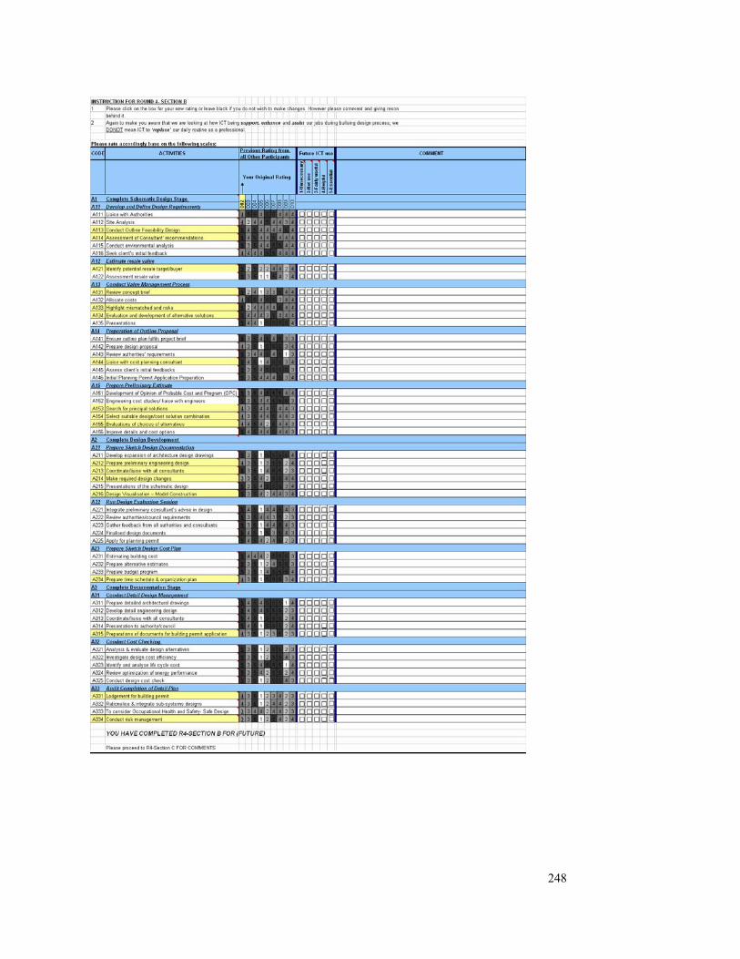
248

249

250
APPENDIX-G REVISED ROUND FOUR SURVEY PACK
NOTICE TO CALL BACK DELPHI ROUND FOUR SURVEY
Dear Delphi Panellist,
Further to the Round 4 Delphi Survey that has been sent out on 18/03/05, few participants
have commented to me that they have some difficulties understanding the questionnaire.
Particularly on the SECTION A & B.
Hence I have decided to recall Round 4 Delphi survey. You are kindly requested to ignore the
survey that has already sent out to you. Meanwhile please note that an amended Round 4
Survey will be prepared and forwarded to you shortly.
Please accept my sincere apology for any inconveniences.
You valuable feedback is critical for this research, and you participation is highly appreciated.
Regards,
casta

251
REVISED- DELPHI ROUND FOUR
Email Notice to begin REVISED Round Four
Dear Delphi Experts,
Thank you for all of the time and effort you have already invested in this research, and I am pleased to
say that this should be the final round. This is also the most important round as we are now seeking to
gain consensus on the need for ICT during all of the design stages.
You will find on the attached summaries all of your answers against those of the other experts.
Please note that this is the amended Round 4 Delphi Survey which would supersede the previous
survey sent to you dated 18th March 2005.
You will find two attachments in this email:-
Attachment 1: Comment made in Round 3 by the Experts
- In this section, we need your comments for the five
statement made by panel members in the previous rounds.
Attachment 2: Round 4 Questionnaire
- Round 4 Questionnaire comprise three sections: Section A, B & C
- In Section A & B, you would find that there are activities that have been highlighted in GREEN colour
in various design stages. These activates are highlighted because your response to these activities
from Round 3 Survey is varied to the "Common View" of the majority of the collected data. In other
words, your comments on these activities are different to most of the other surveyors from our finding.
- In Section A & B, we need your attention and response ONLY on these highlighted activities.
- You would note that in the highlighted activities, the common views from other surveyors are marked
in GREEN. Your response from Round 3 survey is marked in ORANGE which is different to the
Common View.
- You are kindly requested to re-consider carefully your previous responses on these highlighted
activities. If you believe the Common View does represent your opinion then please tick the column
"Agree with the Mode". However, if you still believe that your previous response reflects the true
situation of your practice then please select "Disagree with the Mode" and provide your reason in
"Your Comment" column.
- In Section C, we need your general comments regarding to Round 4 Survey. If there is anything you

252
believe that would be beneficial for this research please specify in this section.
I would appreciate you completing this round by 17th April, and if you need any further assistance then
please contact me by email at [email protected] (preferably) / [email protected] .
Once I have analysed all of the responses, I will send you a copy of the process map which highlights
the activities where ICT will assist the design stages of construction projects, as well as a summary of
the findings.
Thank you again for all of your assistance on this research project, it would not have been possible
without your help.
Regards,
Casta

253
Comments made in Round 3 by the Experts-REVISED
1. The design and evaluation activities are highly depend on the staff’s expertise and
experience of individual practice. Whilst ICT has proven beneficial for
communication and information management, it will not replace the expertise and
experience of a design team. Do you agree with the above statements?
What is your comment?
2. The variety and type of ICT infrastructure available on the marketplace is not a major
concern to the industry. Because the construction industry is capable to adjust its
operation process to suit the available ICT in the marketplace. The major concern for
the industry is whether quality improvement could be achieved by adopting new ICT
software.
What is your comment?
3. ‘Other ICT tools that should be included are: Visualisation tools (4D CAD, VR, GIS);
Management tools (document management, construction planning, cost planning,
digital photography); Communication tools (Voice over IP, mobile communications
such as XDAII), etc.’
Would you agree or disagree that your office’s productivity can be further enhanced if
the above mention ICT tools are used in your current practice.
What is your comment?

254
4. As the evolution of existing softwares is so quickly, often upgrade your existing
software also involves a major hardware improvement. Do you think it is necessary?
What is your comment?
5. Do you agree or disagree that the quality and productivity of various design process
could be further enhanced in the future if an’ integrated communication model’ can
be formed and efficiently implemented among various stakeholders.
What is your comment?
THANK YOU FOR YOUR COMMENTS ON THE ABOVE STATEMENTS,
KINDLY PLEASE PROCEES TO ROUND-4 QUESTIONNAIRE!!!
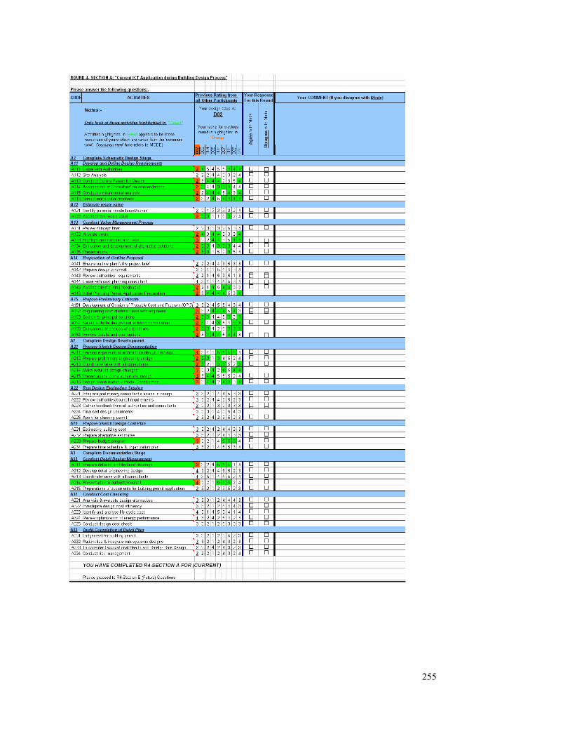
255

256
257