a mathematical and numerical model for the analysis of hybrid
TRANSCRIPT

A Mathematical and Numerical Model for the Analysis of Hybrid Rocket Motors
Marius STOIA-DJESKA*,1,a, Florin MINGIREANU2,b
*Corresponding author *,1 “POLITEHNICA” University of Bucharest, Faculty of Aerospace Engineering,
Gh. Polizu Street 1-7, 011061, Bucharest, Romania [email protected]
2 Romanian Space Agency Str. Mendeleev, 21-25, Sector 1, 010362, Bucharest, Romania
Abstract: The hybrid rocket motors (HRM) use a two-phase propellant system. This offers some remarkable advantages but also arises some difficulties like the neutralization of their instabilities. The non-acoustic combustion instabilities are high-amplitude pressure oscillations that have too low frequencies to be associated with acoustics. Acoustic type combustion instabilities are self-excited oscillations generated by the interaction between acoustic waves and combustion. The goal of the present work is to develop a simplified model of the coupling of the hybrid combustion process with the complete unsteady flow, starting from the combustion port and ending with the nozzle. This model must be useful for transient and stability analysis and also for scaling of HRMs. The numerical results obtained with our model show a good agreement with published experimental and numerical results. The computational and stability analysis models developed in this work are simple, computationally efficient and offer the advantage of taking into account a large number of functional and constructive parameters that are used by the engineers.
Key Words: hybrid combustion process, hybrid rocket motors, non-linear hyperbolic system
NOMENCLATURE 2AA r = cross section area of the combustion port
rA = cylindrical combustion port radius cp = constant pressure heat coefficient Re = local Reynolds number, u x
p = propellant density
= gas mixture density u = gas mixture axial velocity E = total internal energy per unit mass Δt, Δt* = time step, dual time step Tf = propellant flame temperature r = burning rate CF = friction coefficient R = gas mixture constant T = gas mixture temperature a Associate Professor, Department of Aerospace Sciences “Elie Carafoli”, Polizu 1-7, 011061 bSenior Researcher, Propulsion Department, Str. Mendeleev; Nr.21-25
INCAS BULLETIN, Volume 3, Issue 4/ 2011, pp. 113 – 125 ISSN 2066 – 8201
DOI: 10.13111/2066-8201.2011.3.4.11

Marius STOIA-DJESKA, Florin MINGIREANU 114
Tp = propellant temperature kp = thermal conductivity of the propellant h = convective heat transfer coefficient n = time index during time integration e = cell index Ωe = cell length γ = the ratio of specific heats of a gas
I. INTRODUCTION
HYBRID rocket motors (HRM) are alternative propulsion systems for future aerospace vehicles. The HRMs use a two-phase propellant system. There are two main types of hybrid motors suitable for use in aerospace propulsion systems: the “classic” and the “gas-generator” type HRMs. In the classic HRM the liquid oxidizer is injected into an inert solid fuel grain port. In the gas-generator type hybrid motor a solid propellant is used as the source of a fuel gas in the gas-generator and then this gas is injected into the main combustion chamber together with the oxidizer to complete the chemical reaction. This study deals with the classic type HRM only.
Hybrids have the advantage of using half the plumbing when compared with a liquid rocket motor since pipes are needed only for the oxidizer installation. At the same time the safety in operation of a hybrid is higher than that of a solid rocket motor since a hybrid can be shut down by controlling the oxidizer inflow [4]. It can be said that a hybrid rocket motor has the simplicity of a solid rocket motor while having the performance of a liquid rocket motor. However, because a hybrid has a solid fuel and a liquid oxidizer, one of the main research problems of hybrids is the combustion efficiency.
Due to the nature of interaction between the oxidizer and the solid fuel, the combustion in a hybrid rocket motor is highly dependent on the degree of interaction between the oxidizer and the surface of the solid fuel [4].
The use of an oxidizer and a solid fuel offers some remarkable advantages [7] but also arises some difficulties like the neutralization of their instabilities [8]. The non-acoustic combustion instabilities are high-amplitude pressure oscillations that have frequencies too low to be associated with acoustics. Their mechanism resides in the pressure sensitivity of the combustion process, the coupling between the motor and the oxidizer feed system, the vortex shedding in the aft mixing chamber, and so on [11]. Acoustic type combustion instabilities are self-excited oscillations generated by the interaction between acoustic waves and combustion. Unsteady heat release generates acoustic waves that propagate within the combustor. If they reflect from the solid boundaries they arrive back at the combustion zone, where they cause more unsteady heat release and thus this feedback can result in large self-excited oscillations. Much of the research in the field of hybrid propulsion is directed toward a clear understanding of the combustion instability phenomenon. The turbulence complicates any analysis because of its interaction with the mean and acoustic flow fields and further with the burning propellant surface and flame region. Each propellant combination has its unique regression rate formula due to the differences in the thermo physical and thermo chemical properties of the components of the propellant and thus such a model includes some key operational parameters that are known and used by engineers in the design process. Hence, a study of the mutual coupling between the flow and propellant combustion dynamics is essential [9].
INCAS BULLETIN, Volume 3, Issue 4/ 2011
115 A Mathematical and Numerical Model for the Analysis of Hybrid Rocket Motors
In the present work we develop a simplified model of the coupling of the hybrid combustion process with the complete unsteady flow, starting from the injector assembly and ending with the nozzle. This is done by coupling to a simplified inviscid flow model the fuel regression rate law and the local equation for the heat transfer in the propellant. The physical model and its mathematical description are presented in section II. The numerical scheme is described in section III. Test results and their discussion follows in section IV. The conclusions are formulated in section V.
II. GOVERNING EQUATIONS
The accurate simulation of the HRM burning depends on the understanding, modeling and coupling of the particular physical processes that take place. The objective of this chapter is to build up a physical model based on a rational approach and to formulate the corresponding mathematical model.
A. The Physical Model
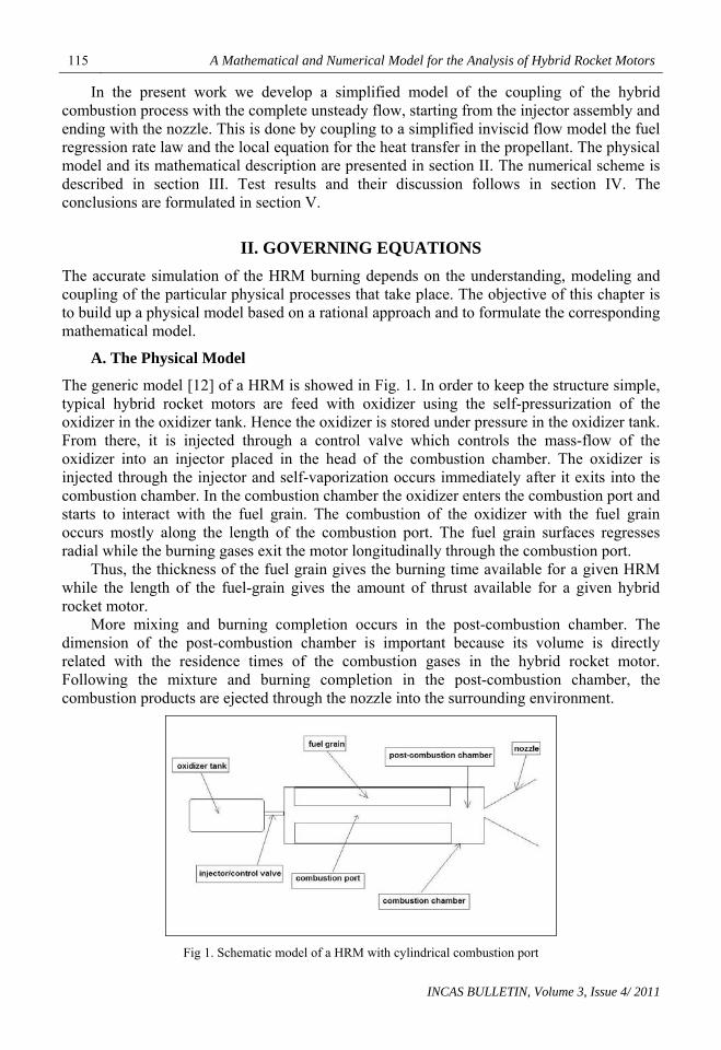
The generic model [12] of a HRM is showed in Fig. 1. In order to keep the structure simple, typical hybrid rocket motors are feed with oxidizer using the self-pressurization of the oxidizer in the oxidizer tank. Hence the oxidizer is stored under pressure in the oxidizer tank. From there, it is injected through a control valve which controls the mass-flow of the oxidizer into an injector placed in the head of the combustion chamber. The oxidizer is injected through the injector and self-vaporization occurs immediately after it exits into the combustion chamber. In the combustion chamber the oxidizer enters the combustion port and starts to interact with the fuel grain. The combustion of the oxidizer with the fuel grain occurs mostly along the length of the combustion port. The fuel grain surfaces regresses radial while the burning gases exit the motor longitudinally through the combustion port.
Thus, the thickness of the fuel grain gives the burning time available for a given HRM while the length of the fuel-grain gives the amount of thrust available for a given hybrid rocket motor.
More mixing and burning completion occurs in the post-combustion chamber. The dimension of the post-combustion chamber is important because its volume is directly related with the residence times of the combustion gases in the hybrid rocket motor. Following the mixture and burning completion in the post-combustion chamber, the combustion products are ejected through the nozzle into the surrounding environment.
Fig 1. Schematic model of a HRM with cylindrical combustion port
INCAS BULLETIN, Volume 3, Issue 4/ 2011

Marius STOIA-DJESKA, Florin MINGIREANU 116
One of the main problems of HRM is the relatively inefficient combustion process within the combustion chamber. Exhausting non-interacted oxidizer reduces the overall performance of the hybrid and this, obviously, is not desired. This is the reason why most of the hybrids are longer than the equivalent solid rocket motor. In this way one tries to keep the oxidizer within the combustion chamber as long as possible in order to give maximum chance for the combustion process to occur.
Based on the functional mechanism of the HRM described previously, we adopt a number of assumptions related to the modeling of the physical phenomena. First, the flow through the HRM combustion port is unsteady, compressible and in an averaged sense, essentially one-dimensional.
Fig. 2. Burning front evolution
The burning surface of the propellant supplies continuously the gases flowing through the channel with combustion products. We assume that there is permanent mixing of the pre-existing gases with the burned gases, so that at each cross-section the kinematic and thermodynamic flow parameters are homogeneous. These flow parameters are supposed to vary continuously and smoothly along the channel. We assume that the mass, momentum and total energy conservation laws can be applied to describe the flow. Second, the viscosity is neglected and its dissipative effects can be eventually taken into account through source terms introduced in momentum and energy equations.
Third, the heat exchange is dominated by the convection. In a cross-section the combustion products originating from the burning area have a temperature completely determined by the thermo chemistry of the combustion. The mixing of the flowing gases with the combustion products is assumed to be instantaneous and thus in the flow equations only the mixture density and temperature are used. The instantaneous pressure is also constant on the cross section. Regarding the velocity, the assumption about the one-dimensionality of the flow leads to the use of only the axial velocity explicitly in the model.
The geometry of the computational domain adopted in this work consists in the combustion port, the post-combustion chamber and the nozzle. Their geometry is given at the beginning of the computations. The left boundary is between the pre-combustion chamber and the combustion port and here are imposed the entrance boundary conditions. The outlet boundary coincides with the nozzle exit. In order to separate the interior from outside a fictitious membrane is positioned at the outlet boundary.
In the present work the ignition phase is not taken into account. The transient computations start when the ignition phase is completed and the oxidizer is discharged through the injector into the combustion chamber. At the end of the ignition and beginning of the feeding with oxidizer the initial density, pressure and temperature conditions in the combustion chamber, combustion port and post-combustion chamber are uniform. They correspond to the thermodynamic state able to start the burning of the mixture. The injection
INCAS BULLETIN, Volume 3, Issue 4/ 2011
117 A Mathematical and Numerical Model for the Analysis of Hybrid Rocket Motors
valve opens progressively up to the main stage level and the pressure rises suddenly. At the initial moment the membrane from the nozzle throat is broken and the flow through the HRM begins. During the transient and due to the fuel grain consumption the geometry of the combustion port changes with time, see Fig.2.
The post-combustion chamber and nozzle cross-section maintain their initial geometry. The sudden changes in the cross-section area along the channel are smoothed through the interpolation included in the numerical solution. Their role in vortices production is not taken into account in our model.
B. Governing Equations and Boundary Conditions
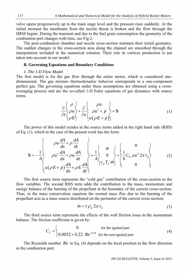
1. The 1-D Flow Model The first model is for the gas flow through the entire motor, which is considered one-dimensional. The gas mixture thermodynamic behavior corresponds to a one-component perfect gas. The governing equations under these assumptions are obtained using a cross-averaging process and are the so-called 1-D Euler equations of gas dynamics with source terms.
2
u
u u pt x
E u E p
S (1)
The power of this model resides in the source terms added in the right hand side (RHS) of Eq. (1), which in the case of the present work has the form:
2 2
0
1 1 10
80
F A
p f
dA dAu
dx dt mdA dA
u u C uA dx dt A
c T mdA dA
u E p Edx dt
2 r
S
(2)
The first source term represents the “cold gas” contribution of the cross-section to the flow variables. The second RHS term adds the contribution to the mass, momentum and energy balance of the burning of the propellant at the boundary of the current cross-section. Thus, in the mass conservation equation the normal mass flux due to the burning of the propellant acts as a mass source distributed on the perimeter of the current cross-section:
2p Am r r (3)
The third source term represents the effects of the wall friction loses in the momentum balance. The friction coefficient is given by:
0.24
for the ignited part
for the non-ignited part
0
0.0032 0.22fCRe
(4)
The Reynolds number Re in Eq. (4) depends on the local position in the flow direction in the combustion port.
INCAS BULLETIN, Volume 3, Issue 4/ 2011

Marius STOIA-DJESKA, Florin MINGIREANU 118
In the current calculations the effect of the third RHS in Eq. (1) source term is neglected. The Eq. (1) is a non-linear hyperbolic system of partial differential equations and is closed by the algebraic state equation for a perfect gas:
2
( 1)2
up RT E
(5)
and
1
1ve c T RT
(6)
One of the main features of this flow model is the full coupling of the pressure field with those related to the flow motion [14]. This allows the calculation of the propagation of acoustic and other low intensity pressure waves through the flow domain and their interaction with the other physicochemical processes.
The mass source term given by Eq. (3) shows that the gas mixture density is directly updated by Eq. (1), to include the combustion effects on the composition of the mixture.
In the present model the gas constant R is not updated following the changes in the mass fractions of the mixture. In a simpler conservative form the system given by Eq. (1) can be written as:
t x
F UU
S U (7)
where the vector of conservative variables and the flux vector are:
2,
u
u u
E u E
p
p
U F U
(8)
The boundary conditions for Eq. (1) are as follows. In the pre-combustion chamber the oxidizer mass flux and density are imposed. At the outlet of the nozzle the unsteady outdoor (atmospheric) pressure is prescribed.
2. The rate regression model The second model is for the propellant burning rate. It is known that for solid rocket motors the quasi steady burning rate is dependent on static pressure following the formula
nr ap (9)
where the constants and have to be determined experimentally. For a HRM a similar relationship has to include the effect of the mass flux of the propellant:
a n
2 ,ln m
A
ur aG p r G
A
(10)
where the parameters , , and l are fuel dependent coefficients determined by experimental burn tests for various pairs oxidizer/fuel.
a n m
INCAS BULLETIN, Volume 3, Issue 4/ 2011

119 A Mathematical and Numerical Model for the Analysis of Hybrid Rocket Motors
Typical values of these coefficients are provided in section IV. The propellant burning rate is also the regression rate for the interface between the fluid and the grain fuel. Thus, it determines both the feeding of the flow with combustion products, Eq. (3), and the modification of the combustion port geometry:
,,Ad r t x
r t xdt
(11)
3. The Heat Conduction Model The last model is for the heat transfer in the fuel grain. Before the ignition of the propellant, the grain surface is heated mainly by convection.
The heat transfer in the longitudinal direction is negligible while the conduction governed heat transfer in the transverse direction (normal to the grain surface) is predominant.
The ignition of the propellant surface at a point begins when at that point the grain attains a critical ignition temperature.
After the ignition, the local surface temperature is the propellant flame temperature Tf. The transient heat conduction in the propellant is governed by:
2
2
p p
p p
T k T
t c
p
z (12)
In Eq. (12) the z coordinate measures the distance from the grain surface towards inside. The unknown of the heat transfer problem is the time-dependent propellant
temperature . , 0pT t z If there is no flame, then the convective heat flux provided by the flow is one of the
boundary conditions:
0
, 0pp p
z
Tk h T T t z
z
(13)
The second boundary condition is the imposed temperature at the opposite boundary. If the fuel grain burns then the surface temperature is:
, 0p fT t z T (14)
and the second boundary condition is the imposed temperature at the opposite boundary. For the heat transfer problem the initial condition is given by the uniform initial
distributed temperature at the end of the ignition. The heat transfer by conduction is not a fast process.
Therefore, the heat penetration rate zone into the fuel grain becomes substantially thinner as burning rate increases.
The flame spreading along the fuel grain surface depends on heating and ignition, and this determines the behavior of the HRM during the transient.
The above three models are coupled through the source terms in Eq. (1) and by the inner boundary condition of the heat transfer problem, Eqs. (13, 14).
INCAS BULLETIN, Volume 3, Issue 4/ 2011

Marius STOIA-DJESKA, Florin MINGIREANU 120
III. COMPUTATIONAL METHOD
The solution procedure is based on the standard cell-centered finite volume scheme of Godunov type [13], coupled with an implicit second-order discretisation in time. At each real time level the solution is obtained by an explicit marching in pseudo-time with a four-stage Runge-Kutta scheme. The main aspects of the solution procedure are presented in the following sections.
The flow domain is divided into cells and the resulting ordinary differential equations which must be solved for the e cell are obtaining by integrating Eq. (7) over the cell length
0,
1,2,..,
e ee
d
dte N
UR U
(15)
where is the cell length, the vector of the conservative variables is e
e
e
e
t u U t
E
dx
U (16)
and the residual eR U results from Eq. (1) and Eq. (7):
1 1
2 2
e ee e
e R F F S (17)
The numerical fluxes at cells faces are evaluated using Roe’s flux-difference scheme, for both the compressible and incompressible equations. The Roe’s solver replaces the exact Riemann solver required in the Godunov method to determine the flow variables at the interface between two finite volumes.
The advantage of the Roe solver is its robustness and easy to implementation. Formally, the normal numerical flux is given by [17]:
1 e e+1 e e+1e+2
e e+1 e e+1
1F U ,U = F U + F U +2
+ A U ,U U - U (18)
The third term in the right hand side of Eq. (18) represents the numerical dissipation that assures the numerical stability of the scheme.
The second order spatial accuracy is obtained by linearly expanding the cell-centered values to each cell face. In this approach the gradients of the conservative variables are computed by a data-independent least-squares method.
To maintain the monotonic character of the scheme we use slope limiters applied to gradients in the regions where steep gradients and/or shocks are present. The limiters are of minmod type [14].
Due to the presence of the very strong source terms in the governing equations and in order to avoid the use of very small type steps, an implicit algorithm is used for time advancement. A second-order backward differentiation of the time derivative leads to the algebraic system [18]:
INCAS BULLETIN, Volume 3, Issue 4/ 2011

121 A Mathematical and Numerical Model for the Analysis of Hybrid Rocket Motors
1 1
13 4
2
1,2,..,
n n n
e e e e e e net
e N
U U UR U 0
(19)
Following Jameson’s idea, a derivative with respect to a fictitious time, is added to Eq. (19) to obtain the following initial value problem:
*t
* **
*
0,
1,2,..,
0
ee
n
e e e
dt
d t
e N
t
WR W
W U
(20)
with and
1not
n
e e
U W
1
* 2 .53
2
n n
e e
t t
U UR W W R W
(21)
A convenient low-storage and second-order accurate explicit multi-stage Runge-Kutta scheme [16] is used to solve Eq. (20). However, for small physical time steps, the explicit Runge-Kutta scheme can lead to an unstable behavior. This is somehow counter-
intuitive but can be explained through the presence of the term in the residual
(21), which is treated explicitly in the Runge-Kutta scheme.
t
13 2 t
W
This leads to a limitation of the dual time step from stability reasons [18]. In a one-dimensional case, it is easy to prove that the upper limit of the time step can be taken following the rules:
* 1
32
ee e
e
tV c
t
(22)
The implicit treatment of the above mentioned term considerably improves the behavior of the dual-time Runge-Kutta scheme and this is the way in which the algorithm is implemented in the code.
The temperature of the propellant in the vicinity of the cell e is obtained by solving
Eq. (12) using the same implicit algorithm.
IV. RESULTS AND DISCUSSION
The numerical simulation of the 1-D compressible flows coupled with the thermal conduction equation inside the solid propellant and the fuel regression rate law allows the calculation of the kinematic and thermodynamic variables throughout the flow field and fuel grain. The burning chamber pressure, temperature and density as functions of time are typical examples.
INCAS BULLETIN, Volume 3, Issue 4/ 2011

Marius STOIA-DJESKA, Florin MINGIREANU 122
Further, used as virtual test facility, the code offers also global performances of the HRM like the thrust versus time and the total impulse.
Fig. 3 Numerical thrust curves for the RATTWORKS K-240 HMR
In order to validate our code we have chosen the well documented test case of the K-240 (M2) HRM commercialized by RATTWORKS. This motor uses polypropylene and self-pressurized N2O oxidizer. The manufacturer provides the dimensions, configuration and functional parameters and also the thrust curve and specific impulse obtained on a horizontal static test stand.
The computational grid used in the numerical simulation uses 1000 equally spaced cells and a time step of order 0.005sec.t
For each time step the internal dual time solver required 15-20 iterations to reach convergence. However, there were approximate 14% of situations in which after 20 internal iterations the internal iterations did not converge and thus the solution process has been restarted with a half time step. The calculated thrust diagram for the above HRM is presented in Fig. 3.
The agreement of the calculated and experimentally determined thrust force during the burning time is well. The values of the numerical specific impulse and total impulse are compared with the experimental ones, as is shown in Table 1.
Table 1. Experimental vs. Numerical results for the HRM specific and total impulse
Impulse Experimental Simulation Specific impulse (s) 145.4 149 Total impulse (Ns) 1374 1404
The conclusion of this comparison is that the new computational model is reliable and therefore it can be used for numerical simulations performed for determining the behavior of HRMs or for determining the occurrence of the physical instabilities of HRMs.
Using as a trigger the fluctuation of the outlet pressure, a pressure-linked instability can be induced in the combustion port. Numerically, the instability detector compares the values of the pressure in the center of the post-combustion chamber during the time evolution and an oscillation occurs if:
1 1 1 2 10 and 0n n n n n n n np p p p p p p p (23)
INCAS BULLETIN, Volume 3, Issue 4/ 2011

123 A Mathematical and Numerical Model for the Analysis of Hybrid Rocket Motors
In Fig. 4 we present such an unstable behavior obtained using the same base-case as in the previous calculations. The fluctuating outlet pressure has a frequency of 2000 Hz and amplitude of 0.01 bars.
By increasing the values of the coefficients n, m, l in Eq. (10) the pressure in the center of the post-combustion chamber became unstable from the beginning of the calculations and a low-frequency oscillations occurred.
Fig. 4 Predicted unsteady pressure-time in unstable combustion
The initial frequency was about 51.2 Hz and increased up to 54 HZ. However, more important is the increase of the average pressure per oscillation cycle and this was almost exponentially.
This type of instability appears to be non-linear and thus cannot be predicted by linear analysis.
V. CONCLUSION
In the present work we have developed a simplified model of the coupling of the hybrid combustion process with the complete unsteady flow, starting from the injector assembly and ending with the nozzle. This is done by coupling the fuel regression rate law and the local equation for the heat transfer in the propellant to the one-dimensional Euler equations of gas-dynamics with source terms.
Even they appear to be simple, these non-homogeneous equations include the most geometrical and physicochemical effects, modeled by source-like terms. The flow equations, the thermal conduction equation inside the solid propellant and the fuel regression rate law are solved in a coupled manner. The platform for the flow field simulations is a high order cell-centred finite volume method combined with an implicit time evolution based on a dual-time approach.
The numerical results obtained with this model show a good agreement with published experimental and numerical results. The numerical analysis for the combustion instabilities in the hybrid motor is done in the time domain by examining the behavior of a pressure wave propagating in the combustion chamber. The computational and stability analysis models developed in this work are simple, computationally efficient and offer the advantage of taking into account a large number of functional and constructive parameters that are used by the engineers.
INCAS BULLETIN, Volume 3, Issue 4/ 2011
Marius STOIA-DJESKA, Florin MINGIREANU 124
APPENDIX
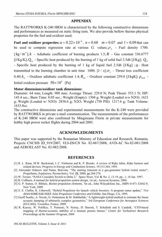
The RATTWORKS K-240 HRM is characterized by the following constructive dimensions and performances as measured on static firing tests. We also provide bellow thermo physical properties for the fuel and oxidizer used.
Fuel and oxidizer properties: , 41022.0 a 68.0n 07.0m
f
and that can be used to compute regression rate at various values;
09.0lG - Fuel density 1700.
[ ]; - Adiabatic coefficient of burning products 1.5;3/ mkg k R - Gas constant 336.6777
[J/Kg/K]; - Specific heat produced by the burning of 1 kg of solid fuel 2.5d6 [J/Kg];
- Specific heat produced by the burning of 1 kg of liquid fuel 2.5d6 [J/Kg] ; - Heat
transmitted to the burning chamber in unit time 1000. [J / s];
csQ clQq
c - Thrust loss coefficient
0.40; - Oxidizer adiabatic coefficient 1.4; - Oxidizer constant 259.8 [J/kgK]; -
Initial oxidizer pressure 50 [Pa]
ok oxR510
0oxp
Motor dimensions/oxidizer tank dimensions: Diameter: 64 mm; Length: 908 mm; Average Thrust: 229.0 N; Peak Thrust: 553.1 N; ISP: 145.4 sec.; Burn Time: 8.05 sec.; Weight (Empty): 1304 g; Weight (Loaded w/o N2O): 1621 g; Weight (Loaded w/ N2O): 2838.6 g; N2O; Weight (750 PSI): 1217.6 g; Tank Volume: 1633.8cc. The constructive dimensions and experimental measurements for the K-240 were provided by RATTWORKS in private e-mail communication. The measurements of the performances of K-240 HRM were also confirmed by Mingireanu Florin in private measurements for hobby high power rocket flights during 2004 and 2005.
ACKNOWLEDGMENTS
This paper was supported by the Romanian Ministry of Education and Research, Romania, Projects CNCSIS ID_919/2007, VLS-DS/CN No. 82-067/2008, AVD-AC No.82-081/2008 and AEROELAST No. 82-082/2008.
REFERENCES
[1] R. L. Raun, M.W. Beckstead, J. C. Finlinson and K. P. Brooks. A review of Rijke tubes, Rijke burners and related devices. Progress in Energy and Combustion Science, 19:313.364, 1993.
[2] Alexander Osherov and Natan, Benviste, “The starting transient in a gas-generator hybrid rocket motor”, Propellants, Explosives, Pyrotechnics, Vol. 25, 2000, pp.260-270.
[3] W. Terster, “NASA Considers Switch to Delta 2,” Space News, Vol. 8, No. 2, 13-19, pp., 1, 18 Jan. 1997. [4] B. Collburn, A manual for hybrid propulsion system design, 1st ed., Aerocon Systems, 2006. [5] G. P. Sutton, O. Biblarz, Rocket propulsion elements, 7nt ed., John Wiley&Sons Inc., ISBN 0-471-32642-9,
New York, 2009. [6] S. E. Claflin, R. J.Harwell, “Hybrid Propulsion for launch vehicle boosters: A program status update,” 31st
AIAA/ASME/SAE/ASEE Joint Propulsion Conference and Exhibit, San Diego, CA, 1995, [7] Geoff Searby, A. Nicole, G. Ordonneau & M. Habiballah, “A lightweight hybrid method to estimate the linear
acoustic damping of arbitrarily complex geometries,” 3rd European Conference for Aerospace Sciences (EUCASS), Versailles, France, 2009.
[8] R. Kaessy, W. Polifkey, T. Poinsotz, N. Noiray, D. Duroxk, T. Schullerk and S. Candelk, “CFD-based mapping of thermo-acoustic stability of a laminar premix burner,” Center for Turbulence Research Proceedings of the Summer Program, 2008
INCAS BULLETIN, Volume 3, Issue 4/ 2011

125 A Mathematical and Numerical Model for the Analysis of Hybrid Rocket Motors
INCAS BULLETIN, Volume 3, Issue 4/ 2011
[9] Florin Mingireanu, Hybrid rocket motor internal ballistic model and oxidizer doping. Applications.”, Proceedings of 4th International Conference RAST 2009, ISBN: 978-1-4244-3626-2, June 2009.
[10] T. V. Chelaru, Florin Mingireanu, “Hybrid rocket engine, theoretical model and experiment”, Acta Astronautica (to be published).
[11] Rocker Marvin, “Simulation of non-acoustic combustion instability in a hybrid rocket motor”, NASA technical report, Marshall Space Center, 1990.
[12] M. Chiaverini and Kenneth K. Kuo (ed.), Fundamentals of Hybrid Rocket Combustion and Propulsion, Progress in Astronautics and Aeronautics, American Institute of Aeronautics and Astronautics, Inc., Reston, Virginia, 2007.
[13] S. K. Godunov, (ed.), Numerical Solution of Multi-Dimensional problems in Gas Dynamics, Nauka Press, Moscow, 1976.
[14] E. F. Toro, Riemann Solvers and Numerical methods for Fluid Dynamics, Springer-Verlag, Berlin, Heidelberg, 2007.
[15] Ch. Hirsch, Numerical Computation of Internal and External Flow, John Wiley and Sons, new-York, 1990. [16] A. Jameson, W. Schmidt and E. Turkel, Numerical Solution of the Euler Equations by Finite Volume
Methods using Runge-Kutta Stepping Schemes, AIAA Technical Report 81-1259, 1981. [17] P. L. Roe, Approximate Riemann Solvers, Parameter Vectors, and Difference Schemes, J.Comput. Phys., 43,
pp. 357-372, 1984. [18] A. Gaitonde, A Dual-Time method for Two-Dimensional Unsteady Incompressible Flow Calculations,
Int.J.Numer.Meth.Engng., 41, pp.1153-1166, 1998.