a method for verification of computer-aided design model...
TRANSCRIPT
Journal of Engineering DesignVol. 16, No. 3, June 2005, 337–352
A method for verification of computer-aideddesign model errors
J. YANG*†, S. HAN† and S. PARK‡
†Korea Advanced Institute of Science & Technology, Korea‡Chungnam National University, Korea
Computer-aided design (CAD) models have errors that originate from data loss during the data con-version process or the technical weakness of the neutral format. Error recovery requires an increasein lead-time and additional expenses for product development. The serious problem is that errors in aCAD model are not found until after downstream development processes. In this paper, we proposea method to identify CAD model errors that are contained in a neutral format. Considering differenttopological and geometrical characteristics in the exchange of product model data (STEP) and initialgraphics exchange specification (IGES) formats, our method includes a verification process to checka CAD model error step by step without wasting resources. To test the idea, we have implemented averification system that checks topological and geometrical errors of 19 items in the STEP format and12 items in the IGES format.
Keywords: Data exchange; Geometry; IGES; Model error; STEP; Topology; Verification
1. Introduction
During a product development cycle, various computer-aided design (CAD) systems are used.They can be classified into a vertical relationship and a horizontal relationship according tothe data stream among them. Hyundai Motors uses Pro/Designer and ALIAS for style design,CATIA for designing engineering parts and assemblies, and Pro/Engineer for designing powertrains. In a horizontal relationship, the design data should be shared among upperstream appli-cations of CATIA, Pro/Engineer, and ALIAS during the collaborative design stage amongvarious disciplines inside the company. In a vertical relationship, model data from an upper-stream application is converted into downstream applications such as finite element analysis,rapid prototyping and numerical control manufacturing.
CAD model data are being exchanged between systems, using a neutral format such as thestandard for the exchange of product model data (STEP) or initial graphics exchange specifi-cation (IGES). However, both the data loss during the conversion process and the structuralweakness of the neutral format cause errors in the CAD models (Yang et al. 2004b). Becausea designer cannot easily find CAD model errors like small gaps, designers waste 20–50% oftheir time repairing or recreating CAD models (Tassey 1999).
*Corresponding author. Email: [email protected]
Journal of Engineering DesignISSN 0954-4828 print/ISSN 1466-1837 online © 2005 Taylor & Francis Group Ltd
http://www.tandf.co.uk/journalsDOI: 10.1080/09544820500126565
338 J. Yang et al.
We can trace a CAD model error from the designer side. If a designer generates a modelbased on the wrong method without observing the rules required by the CAD system, bugsor flaws are contained in the CAD model. The error propagates or diffuses into downstreamCAD systems during data exchanges. Those errors are frequently found in the final stage suchas mould manufacturing or finite element analysis (Yang et al. 2004a). To solve this problem,designers occasionally depend on their intuition.
There has been research on the verification of CAD models in restricted areas. Hoffmanand Robert (1998) approached the model errors in the direction of geometric dimensioningand tolerancing, and Gu et al. (2001) studied various errors that exist in a CAD model andtheir theoretical fundamentals. Deshpande et al. (2000) used a method called the ‘comple-mentary model object tree’ to find and fix errors. Barequet et al. (1996), Steinbrenner et al.(2001) and Volpin et al. (1998) approximated the exact shape as a polyhedron form to findgaps and overlaps between polygons. Some previous studies were undertaken as a branch ofcomputational fluid dynamics, computational structural analysis, and mesh generation, wherethe CAD model errors are examined for specific purposes such as gaps or overlaps.
In this paper, we classify the CAD model errors from the viewpoint of topology andgeometry, and we propose a procedural method to find errors. The procedural method avoidsduplicating the evaluation process and executes a systematic error verification based on thequantitative input of the designer. The CAD model formats that we have used are STEPAP214,which is for automotive mechanical design processes, and IGES v5.3. Using the implementedCAD model error verification system, we can verify 19 errors in the STEP format and 12errors in the IGES format. We have tested this system on automotive parts with the courtesyof Hyundai Motors.
2. Procedural approach of error verification
2.1 Error classification
The error items to be verified are based on the Japan Automobile Manufacturers’AssociationProduct Data Quality Verification Model Data Specifications, version 2.0 (Japan AutomobileManufacturers’ Association 2002). Among the 45 error items of the Japan AutomobileManufacturers’ Association Product Data Quality Verification Model Data Specifications,the 19 error items that the Hyundai Motors’ designers put as high priority are handled.
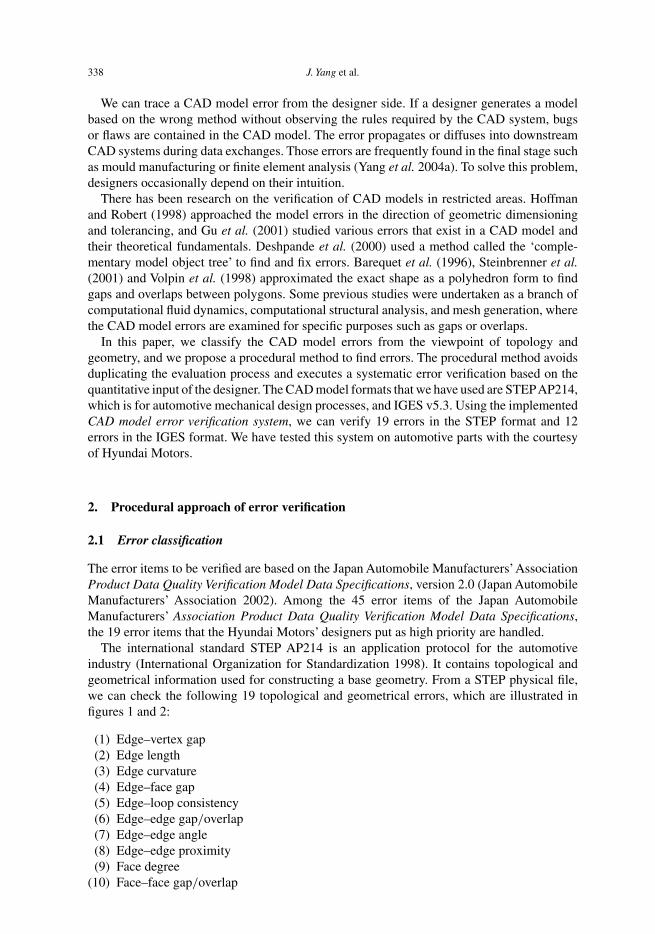
The international standard STEP AP214 is an application protocol for the automotiveindustry (International Organization for Standardization 1998). It contains topological andgeometrical information used for constructing a base geometry. From a STEP physical file,we can check the following 19 topological and geometrical errors, which are illustrated infigures 1 and 2:
(1) Edge–vertex gap(2) Edge length(3) Edge curvature(4) Edge–face gap(5) Edge–loop consistency(6) Edge–edge gap/overlap(7) Edge–edge angle(8) Edge–edge proximity(9) Face degree
(10) Face–face gap/overlap

Verification of CAD model errors 339
Figure 1. Representation of error items (1)–(5) and (7). Nomenclature: vi , the ith vertex; ei , the ith edge.
(11) Face–face angle(12) Face–face consistency(13) Edge–use–count(14) Void–face/surface(15) Curve length(16) Curve curvature(17) Surface degree(18) Surface–surface gap/overlap(19) Surface–surface angle

340 J. Yang et al.
Figure 2. Representation of error items (8)–(10), (14) and (19).
The first 14 items check the solid data and surface data with topological information, and thelatter five items check the surface without topological information.
Most IGES models contain only geometrical information (National Institute of Standardsand Technology 1990). To handle CAD models without a topology, we can extract topologicaldata such as vertices, edges, and loops from the geometrical data; for example, edges fromthe surface boundary curves (IGES entity types 102, 126, 141, and 142) and the faces from
Verification of CAD model errors 341
the surface data (types 143, 144, and 510). As a result, we can identify the following 12 erroritems contained in the IGES format:
(1) Edge (curve) length(2) Edge (curve) curvature(3) Edge–edge gap(4) Edge–edge angle(5) Edge–face gap(6) Edge–edge proximity(7) Edge–loop consistency(8) Surface–surface consistency(9) Surface degree
(10) Surface–surface gap(11) Surface–surface angle(12) Void–surface
2.2 Approaches for STEP models
STEP Tools Ltd’s ST-Developer version 8.0 is used to read and manage STEP models withtopological structures (http://www.steptools.com/products/stdev/index.html). Browsingand searching all the data stored in the internal data structure is possible usingST-Developer application programming interfaces (APIs) and our own evaluationfunctions. The verification result is managed as an independent data structure. Wehave used OpenCASCADE version 3.0 modules in which low-level functions are avail-able for mathematical analysis and the verification modules that are implementedfor geometric analysis (http://www.opencascade.com/). The mapping module allowscommunication of the internal data structure with the ST-Developer and OpenCASCADE.We have used the following seven shape_representation forms of STEP when creating a part:
1. advanced_brep_shape_representation2. manifold_surface_shape_representation3. geometrically_bounded_surface_shape_representation4. faceted_brep_shape_representation5. geometrically_bounded_wireframe_shape_representation6. hybrid_3d_shape_representation7. csg_shape_representation
Only advanced_brep_shape_representation, manifold_surface_shape_representation, andgeometrically_bounded_surface_shape_representation are allocated for the full errorverification process. The others ended with a warning sign. In particular, the shapefaceted_brep_shape_representation only sends the message ‘faceted_solid is used’ to thedesigner, which means a faceted solid is used in this STEP model, and the message is writtenat the end of the report file.
As shown in figure 3, (1) advanced_brep_shape_representation is used for normalsolid data, and (2) manifold_surface_shape_representation has a topological set of facesthat consist of a shell unit. As both cases consist of a number of faces with a list ofedges, we can find topological errors based on these entities. However, since geometri-cally_bounded_surface_shape_representation consists of a number of surfaces without atopological relationship, we can find those errors after creating boundary curves from each

342 J. Yang et al.
Figure 3. The procedural verification process of the STEP model.
surface. The bigger the STEP data file becomes, the more time and memory is spent onsearching the internal data and confirming its connectivity. Consequently, to improve the ver-ification performance, we have grouped the verification processes and their functions basedon similarity and organized their processing procedurally, as shown in figure 3.
2.3 Approaches for IGES models
An IGES model consists of geometrical data, not topological data – that is, IGES consists ofpoint entities, line entities, curve entities, surface entities, and solid entities. To implementverification algorithms for geometrical entities without topology, we extract topological datasuch as vertices, edges, and loops from the boundary curves (IGES entity types 102, 126,141, and 142) for a surface that has a geometrical datum. Similarly, faces are extracted froma surface (types 143, 144, and 510) with boundary curves. For the surface that does not haveboundary curves (types 108, 114, 118, 120, 122, 128, and 140), we find out boundary curvesusing U-parameters and V-parameters.
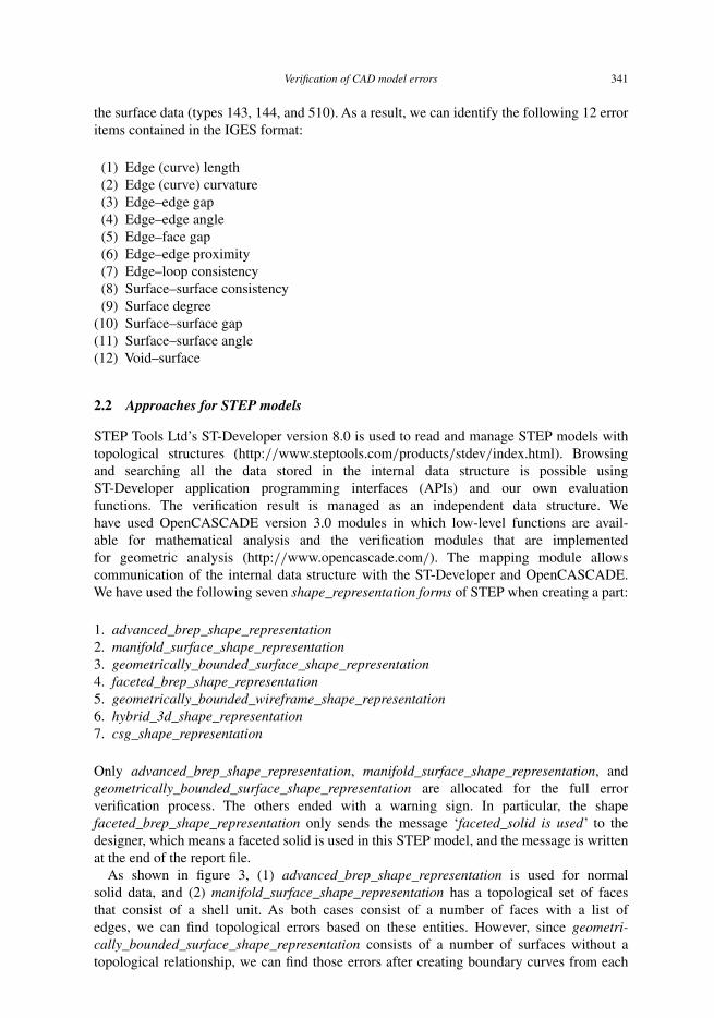
There are two verification workflows; Process I for the boundary curve data and Process IIfor the surface data. The whole process finishes in three steps. In the first step, the evaluationprocesses of edge (curve), loop, and surface are executed in sequence. The verification processof the candidate sewing edge is achieved in the second step. In the final step, based on thepreceding two processes, the verification of between surfaces is executed. To improve theperformance of the verification process and to avoid redundancy in the verification modules,we divided the two processes based on the verification targets and the three layers accordingto the verification tasks, as illustrated in figure 4. In addition, independent modules allowindividual verifications. The verification system for IGES models consists of 13 modulesincluding the verification of the candidate sewing edge.
Verification of CAD model errors 343
Figure 4. The procedural verification process of the IGES model.
2.4 Categorization of verification items
The categorization of verification items are presented in table 1.
3. Implementation
3.1 System architecture
As shown in figure 5, a configuration file that includes verification conditions and criteria,as well as a model file such as STEP or IGES, are loaded into the verification system. TheSTEP file is translated into the internal data structure through the ST-Developer. The verifi-cation operation for topology and geometry is performed by means of the low-level APIs ofOpenCASCADE such as mathematical computations in addition to the solver functions thatwe have developed. The postprocessor of this system adds special entities to the geometricentities or shapes where the errors occurred. The added entity is a colour, a descriptive text,or a symbol. The purpose of adding the entity is to help designers to locate the errors. Thesystem produces two types of verification results: one type for ordinary users and one forsystem administrators.
3.2 Input and output files
3.2.1 Input configuration file. The configuration file is divided into three areas: the quan-titative criterion area for each verification item; the area for the error indication; and the areafor reporting options. The file can be customized according to the design guides prescribedby a user company.

344 J. Yang et al.
Tabl
e1.
Cat
egor
izat
ion
ofve
rific
atio
nite
ms.
Cat
egor
yV
erifi
catio
nite
mD
escr
iptio
n
Edg
eer
rors
Lar
gega
pbe
twee
nve
rtex
and
edge
C0
disc
ontin
uity
.Aft
erm
easu
ring
adi
stan
cebe
twee
nth
ree-
dim
ensi
onal
(3D
)po
ints
linke
dto
ave
rtex
and
apo
intt
hati
spr
ojec
ted
ona
curv
efr
omth
atve
rtex
poin
t,ch
eck
ifits
dist
ance
islo
nger
than
the
user
’sin
put
valu
eSm
alll
engt
hof
aned
geor
acu
rve
Tin
yse
gmen
t.C
onsi
der
zero
leng
thif
the
leng
thof
ase
ctio
ncu
rve
dete
rmin
edby
each
vert
exis
smal
ler
than
the
give
nva
lue
orif
the
coor
dina
teva
lues
oftw
ove
rtic
eson
aned
gear
eal
mos
tequ
alH
igh
curv
atur
eof
aned
geor
acu
rve
Cur
led
segm
ent.
Aft
erob
tain
ing
two
para
met
ers
from
acu
rve,
divi
deth
emin
to20
piec
esan
dm
easu
reth
ecu
rvat
ure
atth
epo
into
fits
curv
eco
rres
pond
ing
toea
chpa
ram
eter
Loo
per
rors
Hig
hde
gree
offa
ces
orsu
rfac
esC
heck
ifth
eex
cess
ive
high
degr
eein
the
U/V
para
met
ers
ofa
B-s
plin
esu
rfac
eis
used
Lar
gega
pbe
twee
nan
edge
and
afa
ceT
hebo
unda
ryof
the
surf
ace
isge
nera
ted
by3D
curv
esin
3Dsp
ace
orby
two-
dim
ensi
onal
(2D
)cu
rves
ina
2Dpl
ane.
For
a2D
curv
e,no
gap
exis
tsbe
twee
nth
efa
cean
dth
eed
gebe
caus
eth
atcu
rve
ison
the
U/V
-par
amet
erpl
ane.
How
ever
,in
mos
tcas
esth
ega
pis
caus
edby
3Dcu
rves
whi
lem
appi
ngfr
omth
e2D
para
met
ric
dom
ain
toth
e3D
spac
edo
mai
n–
this
phen
omen
onis
due
toth
eC
AD
syst
em’s
tole
ranc
eE
dge/
loop
cons
iste
ncy
Insp
ectt
heco
nnec
tivity
ofev
ery
loop
,whi
chin
turn
cons
ists
ofa
listo
fed
ges,
acco
rdin
gto
thei
rdi
rect
iona
lm
eani
ng.T
hedi
rect
ion
ofea
ched
ge,i
nca
seof
aST
EP
file,
isde
term
ined
byth
etw
ove
rtic
esed
gest
art
and
edge
end.
Inad
ditio
n,or
ient
eded
geis
used
for
givi
nga
dire
ctio
nalm
eani
ngto
edge
sin
alo
opL
arge
gap
orov
erla
pbe
twee
ned
ges
Che
ckth
ele
ngth
ofth
ega
pbe
twee
ntw
one
ighb
ouri
nged
ges
bym
easu
ring
the
dist
ance
betw
een
ever
ypr
ojec
tion
poin
tof
the
vert
exth
atsh
ared
two
conn
ecte
ded
ges
Shar
pan
gle
betw
een
edge
sM
easu
reth
ean
gle
betw
een
two
tang
entv
ecto
rsfr
omth
ele
fted
gean
dth
eri
ghte
dge
onth
eba
sis
ofa
vert
exw
here
the
two
edge
sm
eet.
The
veri
ficat
ion
proc
ess
isus
edno
tonl
yfo
rth
ene
ighb
ouri
ngst
ate
betw
een
two
edge
s,bu
tals
ofo
run
real
anom
alou
ssh
apes
Edg
epr
oxim
ityPr
oduc
ing
dist
orte
dfa
ces
such
asa
long
,thi
nsh
ape
ispo
ssib
ledu
eto
ade
sign
erfa
ulto
ra
diff
eren
cein
the
tole
ranc
eof
CA
Dsy
stem
s.M
ostp
roxi
mity
erro
rsha
ppen
whe
nan
edge
has
zero
leng
th.C
heck
ifa
righ
ted
gean
da
left
edge
mee
tata
zero
gap
Face
erro
rsE
dge–
use–
coun
tB
asic
info
rmat
ion
tofin
dth
eer
rors
conn
ecte
dw
ithfa
ces.
Whe
nth
ety
peof
shap
ein
STE
Pis
shel
lba
sed
surf
ace
mod
el,f
orex
ampl
e,th
eed
ge-u
seco
unto
fm
any
edge
sis
1be
caus
eal
thou
gha
shel
lha
sin
tern
alto
polo
gica
lin
form
atio
n,th
eST
EP
mod
elof
shel
lba
sed
surf
ace
mod
eldo
esno
tin
clud
eth
eco
nnec
tivity
betw
een
shel
ls.
So,
itis
hard
tofin
dth
eco
nnec
tivity
betw
een
two
face
sw
ithou
tth
eed
ge–u
se–c
ount
proc
ess
Lar
gega
pan
dov
erla
pbe
twee
nfa
ces
Che
ckif
the
gap
betw
een
the
two
face
ssh
arin
gth
eed
geis
mor
eth
anth
ein
putv
alue
Shar
pan
gle
betw
een
face
sT
hean
gle
prob
lem
occu
rsbe
twee
ntw
ofa
ces
intw
osi
tuat
ions
:whe
ntw
ofa
ces
mak
ea
shar
pan
gle,
and
whe
nth
ein
form
atio
nof
the
face
’sno
rmal
vect
oris
inco
rrec
tlysp
ecifi
ed.T
hefir
stsi
tuat
ion,
whi
chpr
oduc
esan
impr
actic
alsh
ape,
islik
ely
tom
ake
trou
ble
inth
eC
AM
proc
ess;
the
othe
ris
anin
corr
ectl
inka
gebe
twee
ntw
ofa
ces
due
toth
eC
AD
tran
slat
or’s
erro
ror
ade
sign
faul
t
(con
tinu
ed)

Verification of CAD model errors 345
Tabl
e1.
Con
tinue
d.
Cat
egor
yV
erifi
catio
nite
mD
escr
iptio
n
Inco
nsis
tenc
ybe
twee
nfa
ces
Ina
solid
mod
el,o
need
geis
used
twic
eby
two
face
s.A
lthou
ghth
eed
gesh
ould
have
been
used
for
the
oppo
site
dire
ctio
nsof
both
face
s,if
itsdi
rect
ions
are
nota
ltern
atel
yus
edin
each
face
the
norm
alve
ctor
coul
dno
tkee
pth
etw
ojo
ined
face
sco
nsis
tent
Con
nect
ivity
ofsu
rfac
esw
ithou
ttop
olog
yC
andi
date
sew
ing
edge
Alth
ough
ther
eis
noto
polo
gica
lin
form
atio
nbe
twee
ned
ges
who
seed
geus
eco
unt
was
1,w
ech
ecke
dth
ege
omet
rica
lco
nnec
tivity
usin
gm
axim
umdi
stan
ces
and
angl
esbe
twee
ntw
osu
rfac
es.F
ora
surf
ace,
we
crea
ted
boun
dary
curv
esbe
caus
eth
ere
was
node
finite
edge
todi
vide
itsbo
rder
.To
crea
teth
ebo
unda
rycu
rves
ofa
surf
ace
with
outt
opol
ogy,
we
appl
ied
U-p
aram
eter
san
dV
-par
amet
ers
inth
epa
ram
etri
cdo
mai
n.Fu
rthe
rmor
e,fo
rth
esu
rfac
esw
ithbo
unda
ries
such
asth
ege
omet
rica
lly
boun
ded
surf
ace
ofST
EP,
we
chec
ked
thei
rco
nnec
tivity
byha
ndlin
gth
eir
boun
dari
esw
ithed
ges
asto
polo
gica
lmea
ning
Voi
dfa
ceD
urin
gth
eco
nver
sion
from
aC
AD
syst
emto
STE
Por
IGE
S,so
me
face
soc
casi
onal
lydi
sapp
ear.
Ifth
atpr
oble
mha
ppen
s,a
CA
Dm
odel
nolo
nger
rem
ains
solid
buti
stu
rned
into
face
unit
data
orsu
rfac
eun
itda
ta.S
o,ch
eck
the
poss
ibili
tyof
avo
idfa
ceby
chec
king
whe
ther
thos
eed
ges
wer
elin
ked
toea
chot
her
and
goti
nto
alo
op

346 J. Yang et al.
Figure 5. Architecture of the CAD model verification system.
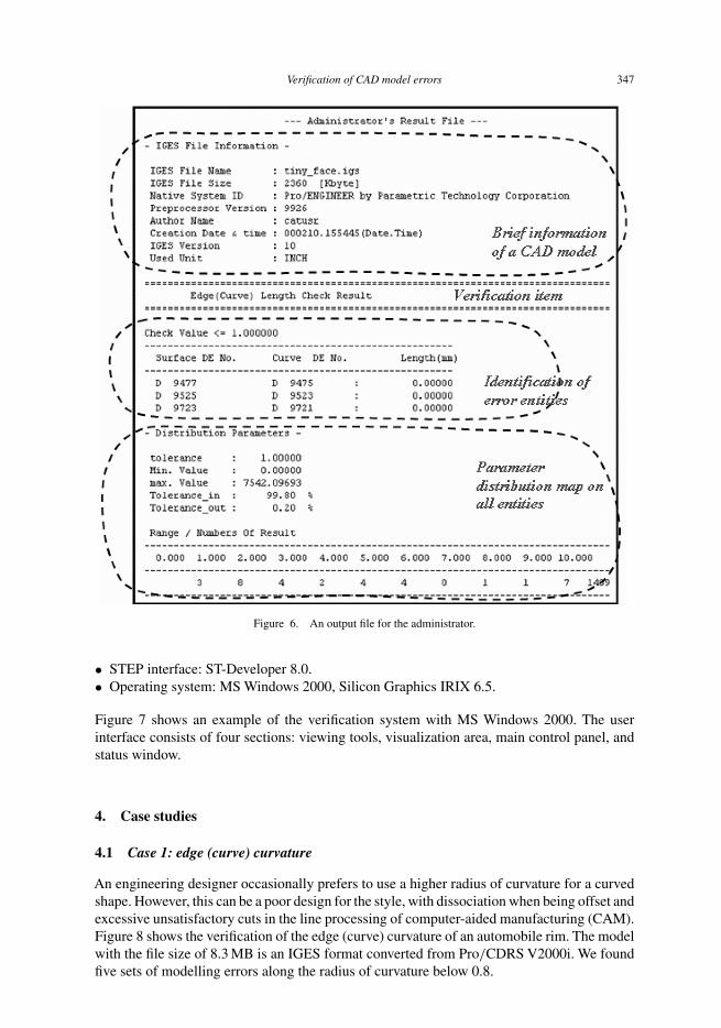
3.2.2 Output log file. After we have completed the error verification of 19 STEP itemsand 12 IGES items, the results are expressed as a log file and a modified physical STEP orIGES file to help designers making decisions. In ASCII form, as shown in figure 6, the log fileincludes a general description of the checked model, the verification results, and the identitiesof the erroneous entities.
Furthermore, to help handling erroneous entities, the system generates a modified STEP orIGES model with special signs and symbols such as colour or indicators as requested by theconfiguration file. For instance, in the IGES output log file, which is shown in figure 6, thefirst block includes a general description of the IGES model such as the file name, size, andversion. The second block shows criteria values that the designer inputted, and the location oferror entities, inclusive of their parents and values. In the last block, maximum and minimumvalues for the verification and a deviation ratio on error entities compared with criteria areincluded. In addition, we have used the reference table to learn, on the basis of criteria, thenumber of entities for verification in any range. As a result, we can determine from the tablewhether an entity is good or bad, or just issue a warning.
3.3 Implementation environment
The verification system has been implemented in two types: a batch processing program forUNIX machines, and an interactive application with a visualization module and a graphicaluser interface for Windows NT. Its implemented environment is as follows:
• Programming language: ANSI C/C++.• Graphics library and user interface: OpenGL, Microsoft Foundation Class.• Geometric modelling kernel: OpenCASCADE version 3.0.
Verification of CAD model errors 347
Figure 6. An output file for the administrator.
• STEP interface: ST-Developer 8.0.• Operating system: MS Windows 2000, Silicon Graphics IRIX 6.5.
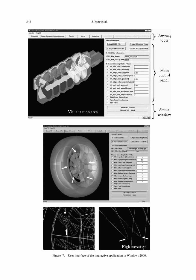
Figure 7 shows an example of the verification system with MS Windows 2000. The userinterface consists of four sections: viewing tools, visualization area, main control panel, andstatus window.
4. Case studies
4.1 Case 1: edge (curve) curvature
An engineering designer occasionally prefers to use a higher radius of curvature for a curvedshape. However, this can be a poor design for the style, with dissociation when being offset andexcessive unsatisfactory cuts in the line processing of computer-aided manufacturing (CAM).Figure 8 shows the verification of the edge (curve) curvature of an automobile rim. The modelwith the file size of 8.3 MB is an IGES format converted from Pro/CDRS V2000i. We foundfive sets of modelling errors along the radius of curvature below 0.8.
348 J. Yang et al.
Figure 7. User interface of the interactive application in Windows 2000.

Verification of CAD model errors 349
Figure 8. Verification result on the edge (curve) curvature.
350 J. Yang et al.
4.2 Case 2: void–face (surface)
A model shape with a tiny face (surface) cannot define cross-sections and cannot beprojected. No offset surface can be achieved. It creates unsatisfactory mesh quality incomputer-aided engineering. Moreover, an excessive amount of time is required for ana-lytical calculation. In CAM, it requires unsuccessful cutting location calculations and cannotbe manufactured.
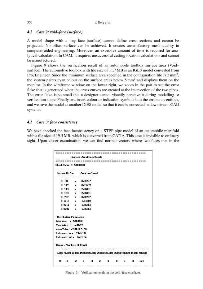
Figure 9 shows the verification result of an automobile toolbox surface area (Void–surface). The automotive toolbox with file size of 11.7 MB is an IGES model converted fromPro/Engineer. Since the minimum surface area specified in the configuration file is 5 mm2,the system paints cyan colour on the surface areas below 5 mm2 and displays them on themonitor. In the wireframe window on the lower right, we zoom in the part to see the errorflake that is generated when the cross curves are created at the intersection of the two pipes.The error flake is so small that a designer cannot visually perceive it during modelling orverification steps. Finally, we insert colour or indication symbols into the erroneous entities,and we save the model as another IGES model so that it can be corrected in downstream CADsystems.
4.3 Case 3: face consistency
We have checked the face inconsistency on a STEP pipe model of an automobile manifoldwith a file size of 19.5 MB, which is converted from CATIA. This case is invisible to ordinarysight. Upon closer examination, we can find normal vectors where two faces met in the
Figure 9. Verification result on the void–face (surface).

Verification of CAD model errors 351
Figure 10. Verification result on the face consistency.
opposite direction to one another. A directional mismatch may result from the offset operation.Moreover, it can abort a tool path-generation process in CAM.
Identifying the angular error between faces by an external visual inspection is difficult.Most angular errors are due to the incorrect normal vector of a face that indicates the oppositedirection to each other. If switching-on ‘back culling’ on the visualization option in the CADsystem, we noticed that a face with incorrect normal vectors disappears as shown in the bottomright of figure 10.
5. Conclusion
Although commercial CAD systems have recently shown stronger power and various func-tions, one problem that distresses designers is the CAD model errors. There are three scenariosfor the source of these errors: designers who use the wrong modelling practices but do notobey the rules required by the CAD system vendor; bugs or technological faults in the CADsystem itself; and incorrect translations that cause data loss and anomalies in the CAD modelwhile exchanging data between heterogeneous CAD systems.
This paper introduces a verification method for CAD model errors, especially the errorsthat occur while converting a commercial CAD model into a neutral model. Until now, most
352 J. Yang et al.
methods of coping with the problem have depended entirely on the CAD system developerand vendor, who know the internal data structure. Likewise, related studies on the errors ofthe neutral model that is frequently used in the field are inactive.
A brief summary of this paper is as follows:
• After considering their structural differences, we analysed the topological and geometricalerrors that can occur on a CAD model, especially neutral models such as STEP and IGES.
• We proposed a procedural method for verification of CAD model errors to save systemresources such as memory and central processor unit sharing. The method has an advantagefor huge CAD models.
• To check errors in IGES or STEP models that do not have topological information, weapplied a method that extracts topological entities form the geometry.
• Based on the analysis, we developed a verification system of CAD model errors; forWindows 2000 with visualization and a graphical user interface, and for UNIX with abatch-processing mode. Using this system, we have tested automotive part models.
Acknowledgement
The authors would like to acknowledge Hyundai Motors for their financial support of thisresearch.
References
Barequet, G., Shapiro, D. and Tal, A. History-driven reconstruction of polyhedral surfaces from parallel slices, inProceedings of the IEEE Visualization, 1996, pp. 149–156.
Deshpande, V., Fornasier, L., Gerteisen, E.A., Hilbrink, N., Mezentsev, A., Merazzi, S. and Wöhler, T. Virtual engi-neering of multi-disciplinary applications and the significance of seamless accessibility of geometry data. FutureGeneration Computer Systems, 2000, 16, 435–444.
Gu, H., Chase, T.R., Cheney, D.C., Bailey, T. and Johnson, D. Identifying, correcting, and avoiding errors in computer-aided design models which affect interoperability. J. Computing Info. Sci. Eng., 2001, 1, 156–166.
Hoffman, C.M. and Robert, J.A. CAD and the product master model. Computer-Aided Design, 1998, 30, 905–918.International Organization for Standardization. ISO 10303-214: 1998 – Industrial automation systems and integra-
tion – Product data representation and exchange, 1998. (The ISO catalogue is at http://www.iso.ch/cate/cat.html;search on 10303 for a listing of parts of the standard.)
Japan Automobile Manufacturers’ Association. Electronic Information Exchange Committee, JAMA/JAPIA PDQVerification Model – Data Specifications, JAMAEIC005, JAMA Inc., Japan, 2002.
National Institute of Standards and Technology, Initial Graphics Exchange Specification (IGES), version 5.0, NISTIR4412, Gaithersburg, Maryland, USA, 1990.
Steinbrenner, J.P., Wynman, N.J. and Chawner, J.R. Procedural CAD model edge tolerance negotiation for surfacemeshing. Eng. Computers, 2001, 17, 315–325.
Tassey, G. Interoperability Cost Analysis of the U.S. Automotive Supply Chain – Final Report (RTI Project Number7007-03), North Carolina, USA, 1999 (Research Triangle Institute).
Volpin, O., Sheffer, A., Bercovier, M. and Joskowicz, L. Mesh simplification with smooth surface reconstruction.Computer-Aided Design, 1998, 30, 875–882.
Yang, J., Goltz, M. and Han, S. Parameter-based engineering changes for a distributed engineering environment.Concurrent Eng.: Res. Applications, 2004a, 12(4), 275–286.
Yang, J., Han, S., Cho, J., Kim, B. and Lee, H. An XML-based macro data representation for a parametric CAD modelexchange. Computer-Aided Design Applications, 2004b, 1, 153–162.