a methodology to apply formal verification to uml-based
TRANSCRIPT

sid.inpe.br/mtc-m21b/2015/09.08.18.24-TDI
A METHODOLOGY TO APPLY FORMALVERIFICATION TO UML-BASED SOFTWARE
Luciana Brasil Rebelo dos Santos
Doctorate Thesis of the Gradu-ate Course in Applied Computing,guided by Drs. Valdivino Alexan-dre de Santiago Júnior, e Nan-damudi Lankalapalli Vijaykumar,approved in Octuber 02, 2015.
URL of the original document:<http://urlib.net/8JMKD3MGP3W34P/3K7T2BB>
INPESão José dos Campos
2015

PUBLISHED BY:
Instituto Nacional de Pesquisas Espaciais - INPEGabinete do Diretor (GB)Serviço de Informação e Documentação (SID)Caixa Postal 515 - CEP 12.245-970São José dos Campos - SP - BrasilTel.:(012) 3208-6923/6921Fax: (012) 3208-6919E-mail: [email protected]
COMMISSION OF BOARD OF PUBLISHING AND PRESERVATIONOF INPE INTELLECTUAL PRODUCTION (DE/DIR-544):Chairperson:Marciana Leite Ribeiro - Serviço de Informação e Documentação (SID)Members:Dr. Gerald Jean Francis Banon - Coordenação Observação da Terra (OBT)Dr. Amauri Silva Montes - Coordenação Engenharia e Tecnologia Espaciais (ETE)Dr. André de Castro Milone - Coordenação Ciências Espaciais e Atmosféricas(CEA)Dr. Joaquim José Barroso de Castro - Centro de Tecnologias Espaciais (CTE)Dr. Manoel Alonso Gan - Centro de Previsão de Tempo e Estudos Climáticos(CPT)Dra Maria do Carmo de Andrade Nono - Conselho de Pós-GraduaçãoDr. Plínio Carlos Alvalá - Centro de Ciência do Sistema Terrestre (CST)DIGITAL LIBRARY:Dr. Gerald Jean Francis Banon - Coordenação de Observação da Terra (OBT)Clayton Martins Pereira - Serviço de Informação e Documentação (SID)DOCUMENT REVIEW:Simone Angélica Del Ducca Barbedo - Serviço de Informação e Documentação(SID)Yolanda Ribeiro da Silva Souza - Serviço de Informação e Documentação (SID)ELECTRONIC EDITING:Marcelo de Castro Pazos - Serviço de Informação e Documentação (SID)André Luis Dias Fernandes - Serviço de Informação e Documentação (SID)

sid.inpe.br/mtc-m21b/2015/09.08.18.24-TDI
A METHODOLOGY TO APPLY FORMALVERIFICATION TO UML-BASED SOFTWARE
Luciana Brasil Rebelo dos Santos
Doctorate Thesis of the Gradu-ate Course in Applied Computing,guided by Drs. Valdivino Alexan-dre de Santiago Júnior, e Nan-damudi Lankalapalli Vijaykumar,approved in Octuber 02, 2015.
URL of the original document:<http://urlib.net/8JMKD3MGP3W34P/3K7T2BB>
INPESão José dos Campos
2015

Cataloging in Publication Data
Santos, Luciana Brasil Rebelo dos.Sa59m A Methodology to apply formal verification to UML-based
software / Luciana Brasil Rebelo dos Santos. – São José dos Cam-pos : INPE, 2015.
xxviii + 168 p. ; (sid.inpe.br/mtc-m21b/2015/09.08.18.24-TDI)
Thesis (Doctorate in Applied Computing) – Instituto Nacionalde Pesquisas Espaciais, São José dos Campos, 2015.
Guiding : Drs. Valdivino Alexandre de Santiago Júnior, e Nan-damudi Lankalapalli Vijaykumar.
1. UML. 2. Formal verification. 3. Model checking.4. SOLIMVA. 5. Formal methods. I.Title.
CDU 004.439
Esta obra foi licenciada sob uma Licença Creative Commons Atribuição-NãoComercial 3.0 NãoAdaptada.
This work is licensed under a Creative Commons Attribution-NonCommercial 3.0 Unported Li-cense.
ii


“Your time is limited, so don’t waste it living someone else’s life.Don’t be trapped by dogma - which is living with the results of otherpeople’s thinking. Don’t let the noise of others’ opinions drown outyour own inner voice. And most important, have the courage to
follow your heart and intuition. They somehow already know whatyou truly want to become. Everything else is secondary.”
Steve Jobs
v


To my beloved family: my son Pedro, my husband Oiram,and my parents Raymundo and Lucimar, who made me a
better person and are the real reasons for my happiness.
vii


ACKNOWLEDGEMENTS
It is so hard on just one page to be grateful for all who contributed to this job. It wasnot only five years. It was the effort of a lifetime. All my experiences and learningswere required and applied here. In advance, I apologize if I forgot to quote someone.
First, there could not be different. I want to thank my parents Raymundo andLucimar. They both really wanted to bring me into this world. Until today, they aremy examples of force, work, fight, and determination, because they were the firstto show me, with their own example, that if we work hard and steady, we achievesuccess. They inspire me in times of trouble! I also thank my brothers, Fátima, Nenê,Jackson, Jefferson, Dinha, and Lene, who always supported me, each one in theirown way. I can feel the pride and respect that you have for me. I love you all, thankyou! I would also like to remind my brother-in-law Edwaldo, that, in my earliestmemories, was the first of the family to encourage me to attend the best universitiesin the country. Only a person with the soul of a poet like him to have that viewbefore all.
I would like to thank my advisors: Dr. Valdivino and Dr. Vijaykumar. Each one, intheir own way, were essential to the progress of this work. Thank you so much foryour friendship, confidence, seriousness, and support whenever it was necessary. Youboth improved my qualities as a researcher and professor. I hope this partnershipwill continue in the course of our lives.
I would also like to thank all my Graduate colleagues, in particular: Michelle, Sherfis,Sabrina, Érica Souza, Érica Golvêa, Juliana Anochi, Juliana Balera, Diego, Marlon,and Alessandro. Thank you so much for all moments of relaxation and joy. Specialthanks to my first pupil, Eduardo, who was essential in the development of thiswork. I hope you decide to continue in Computing.
I want to thank Instituto Nacional de Pesquisas Espaciais (INPE) and CAPES, forthe financial support in this research.
And finally, thank you Oiram, my most precious friend, for being a great partnerand a perfect father for our son. I will never thank you enough for your patience anddedication. You supplied all the needs of our family while I dedicated to my PhD. Ido love you... and thank you Pedro, now you will have your mom back just for you.
ix


ABSTRACT
Software development organizations aim to add quality to the created products,especially those dealing with critical systems, which require high quality software.Formal Methods offer a large potential to provide more effective verification tech-niques. Besides, Formal Verification methods, such as Model Checking, are best ap-plied in early stages of system design, when costs are low and benefits can be high,increasing the quality of systems. Unified Modeling Language (UML) is widely usedfor modeling (object-oriented) software, and its use is increasing in the aerospaceindustry. Verification and Validation of complex software developed according toUML is not trivial due to complexity of the software itself, and the several differ-ent UML models/diagrams that can be used to model behavior and structure of thesoftware. This PhD thesis presents an extension of a methodology called SOLIMVA,initially developed to generate model-based system and acceptance test cases con-sidering Natural Language requirements artifacts (SOLIMVA 1.0), and to detectincompleteness in software specifications by means of Model Checking (SOLIMVA2.0). Such an extension generated SOLIMVA 3.0 which transforms up to three dif-ferent UML behavioral diagrams (sequence, behavioral state machine, and activity)into a single Transition System to support Model Checking of software developedin accordance with UML. In SOLIMVA 3.0, properties are formalized based on usecase models or requirements expressed in pure textual notation. The translationinto the Transition System is done for the NuSMV model checker, but there is apossibility in using other model checkers, such as SPIN. A tool, XML MetadataInterchange to Transition System (XMITS), was developed to automate some stepsof SOLIMVA 3.0 methodology. The approach was applied to two real case studies(embedded software) related to project under development at Instituto Nacional dePesquisas Espaciais (INPE). Defects were detected within the design of these soft-ware systems showing the feasibility of the methodology. The main contribution ofthis PhD thesis is the transformation of a non-formal language (UML) to a formallanguage (language of the NuSMV model checker) towards a greater adoption inpractice of Formal Methods in software development.
Keywords: UML. Formal Verification. Model Checking. SOLIMVA. Formal Methods.
xi


UMA METODOLOGIA PARA APLICAR VERIFICAÇÃO FORMALA SOFTWARE DESENVOLVIDO DE ACORDO COM UML
RESUMO
Organizações que desenvolvem software objetivam produzir produtos de softwarede qualidade, especialmente aquelas que lidam com sistemas críticos, que deman-dam software de alta qualidade. Métodos Formais oferecem grande potencial paraprover técnicas de verificação mais efetivas. Além disso, métodos de Verificação For-mal, como Model Checking, são aplicados de maneira mais eficiente nos estágiosiniciais do projeto de software, quando os custos ainda são baixos e os benefíciospodem ser altos, aumentando a qualidade dos sistemas de software. A Linguagem deModelagem Unificada (UML) é consideravelmente utilizada para modelar software(orientado a objetos), e seu uso tem crescido na indústria aeroespacial. Verificação eValidação de sistemas complexos desenvolvidos de acordo com UML não são tarefastriviais, devido à complexidade do software em si, e a diversos diagramas/modelosUML diferentes que podem ser usados para modelar o comportamento e a estruturado sistema. Esta tese de doutorado apresenta uma extensão de uma metodologiachamada SOLIMVA, desenvolvida inicialmente para gerar casos de teste de sistemae de aceitação baseados em modelos, considerando requisitos em Linguagem Natu-ral (SOLIMVA 1.0), e para detectar não completude em especificações de softwareutilizando Model Checking (SOLIMVA 2.0). Tal extensão gerou a SOLIMVA 3.0, aqual transforma até três diferentes diagramas comportamentais da UML (sequên-cia, atividades e máquina de estado) em um único Sistema de Transição de Estadospara possibilitar a aplicação de Model Checking em software desenvolvido de acordocom a UML. Na SOLIMVA 3.0, as propriedades são formalizadas baseando-se nosmodelos de casos de uso ou em requisitos expressos em notação textual pura. Atradução para o Sistema de Transição de Estados é feita para a ferramenta de Mo-del Checking NuSMV, mas existe a possibilidade de se utilizar outras ferramentas,como por exemplo, SPIN. Uma ferramenta, XML Metadata Interchange to Tran-sition System (XMITS), foi desenvolvida para automatizar algumas atividades dametodologia SOLIMVA 3.0. A abordagem foi aplicada em dois estudos de caso reais(software embarcado) relacionados a um projeto em desenvolvimento no InstitutoNacional de Pesquisas Espaciais (INPE). Foram encontrados defeitos nos projetosdesses sistemas de software, mostrando a viabilidade da metodologia. A principalcontribuição desta tese de doutorado é a transformação de uma linguagem não for-mal (UML) para uma linguagem formal (linguagem de entrada da ferramenta deModel Checking NuSMV), tendo como objetivo uma maior utilização, na prática, deMétodos Formais no processo de desenvolvimento de software.
Palavras-chave: UML. Verificação Formal. Model Checking. SOLIMVA. MétodosFormais.
xiii

LIST OF FIGURES
Page
2.1 Example of UML use case diagram and its description . . . . . . . . . . 122.2 Example of UML sequence diagram using combined fragment opt . . . . 132.3 Activity diagram for the use case Ordering . . . . . . . . . . . . . . . . . 142.4 State Machine for the use case Ordering . . . . . . . . . . . . . . . . . . 172.5 View of a system verification. Baier and Katoen (2008) . . . . . . . . . . 182.6 Schematic view of Model Checking. Baier and Katoen (2008) . . . . . . . 202.7 Visualization of semantics of some basic CTL formulae. Baier and Katoen
(2008) . . . . . . . . . . . . . . . . . . . . . . . . . . . . . . . . . . . . . 242.8 Version 1.0 of SOLIMVA methodology. SANTIAGO JÚNIOR (2011) . . 292.9 Version 2.0 of SOLIMVA methodology. SANTIAGO JÚNIOR (2011) . . 30
3.1 Version 3.0 of SOLIMVA methodology . . . . . . . . . . . . . . . . . . . 413.2 Extending SOLIMVA: contribution of this PhD thesis . . . . . . . . . . . 423.3 TS generated from the SD of Figure 2.2 . . . . . . . . . . . . . . . . . . 513.4 TS generated from the AD of Figure 2.3 . . . . . . . . . . . . . . . . . . 543.5 TS generated from the SMD of Figure 2.4 . . . . . . . . . . . . . . . . . 573.6 Possible situations to generate the unified TS and its respective gvs . . . 593.7 Details of the Rules Dictionary . . . . . . . . . . . . . . . . . . . . . . . 603.8 Combining TSs with no guards . . . . . . . . . . . . . . . . . . . . . . . 613.9 Combining TSs when one TS has guards and the other one does not . . . 623.10 Combining TSs with different guards . . . . . . . . . . . . . . . . . . . . 633.11 NuSMV code for the TS of Figure 3.3 . . . . . . . . . . . . . . . . . . . . 663.12 Context-Free Grammar to convert the output of the Converter or of the
TUTS into the NuSMV Model Checker Notation. . . . . . . . . . . . . . 673.13 ATM Use Case diagram . . . . . . . . . . . . . . . . . . . . . . . . . . . 683.14 Part of ATM Sequence Diagram and its respective TS . . . . . . . . . . . 693.15 Part of ATM Behavioral State Machine Diagram and its respective TS . 703.16 Part of ATM Activity Diagram and its respective TS . . . . . . . . . . . 713.17 Part of the final TS obtained from the three diagrams . . . . . . . . . . . 723.18 Part of the NuSMV code for the TS of Figure 3.17 . . . . . . . . . . . . 733.19 UML diagrams used for ATM example. Adapted from Debbabi et al. (2010) 743.20 Counterexample for property 2 . . . . . . . . . . . . . . . . . . . . . . . 75
4.1 Activities of SOLIMVA 3.0 automated by XMITS . . . . . . . . . . . . . 774.2 Flow diagram of XMITS . . . . . . . . . . . . . . . . . . . . . . . . . . . 784.3 XMITS software architecture . . . . . . . . . . . . . . . . . . . . . . . . 80
xv
4.4 XMITS detailed workflow . . . . . . . . . . . . . . . . . . . . . . . . . . 804.5 Flow diagram of Converter Module . . . . . . . . . . . . . . . . . . . . . 814.6 Package Diagram of Converter Module . . . . . . . . . . . . . . . . . . . 824.7 Package Diagram of TUTS Module . . . . . . . . . . . . . . . . . . . . . 834.8 The iteration over the diagrams in the TUTS module . . . . . . . . . . . 844.9 An example of a diagram and its respective tree . . . . . . . . . . . . . . 864.10 Output file for the diagram shown in Figure 4.9 . . . . . . . . . . . . . . 88
5.1 Physical architecture defined for QSEE project. Caption: ADC = Analog-to-Digital Converter; DAQ = Data Acquisition Board; RS-232 = Rec-ommended Standard 232; USB = Universal Serial Bus. SANTIAGOJÚNIOR (2011) . . . . . . . . . . . . . . . . . . . . . . . . . . . . . . . . 90
5.2 Scenario 1 represented in Statecharts and adapted to UML State Machine 925.3 Sequence Diagram for Scenario 1 . . . . . . . . . . . . . . . . . . . . . . 935.4 Activity Diagram for Scenario 1 . . . . . . . . . . . . . . . . . . . . . . . 945.5 State Machine Diagram for Scenario 1 . . . . . . . . . . . . . . . . . . . 955.6 Part of the unified TS obtained for Scenario 1 . . . . . . . . . . . . . . . 985.7 Sequence Diagram for Scenario 3 . . . . . . . . . . . . . . . . . . . . . . 995.8 State Machine Diagram for Scenario 3 . . . . . . . . . . . . . . . . . . . 1005.9 Part of the unified TS obtained for Scenario 3 . . . . . . . . . . . . . . . 1015.10 Sequence Diagram 1 for Scenario 8 . . . . . . . . . . . . . . . . . . . . . 1025.11 Sequence Diagram 2 for Scenario 8 . . . . . . . . . . . . . . . . . . . . . 1035.12 Sequence Diagram 3 for Scenario 8 . . . . . . . . . . . . . . . . . . . . . 1045.13 State Machine Diagram for Scenario 8 . . . . . . . . . . . . . . . . . . . 1055.14 Part of the unified TS obtained for Scenario 8 . . . . . . . . . . . . . . . 1085.15 Simplified physical architecture of the protoMIRAX balloon experiment.
XRC: X-ray camera; ACS: Attitude Control System; TEMPDXA: Tem-perature monitoring equipment; GPSDXA: GPS unit; OBDH: On-BoardData Handling Subsystem; PDCpM: Payload Data Handling Computer;DC-DC Conv: DC-DC Converter; PRESN: Pressure Sensor; PSS: PowerSupply Subsystem; FCTS: Flight Control and Telecommunications Sub-system. Braga et al. (2015) . . . . . . . . . . . . . . . . . . . . . . . . . . 110
5.16 Sequence Diagram for Scenario 6 . . . . . . . . . . . . . . . . . . . . . . 1125.17 The unified TS obtained for Scenario 6 . . . . . . . . . . . . . . . . . . . 1145.18 Sequence Diagram for Scenario 7 . . . . . . . . . . . . . . . . . . . . . . 1155.19 The unified TS obtained for Scenario 7 . . . . . . . . . . . . . . . . . . . 1165.20 Sequence Diagram for Scenario 8 . . . . . . . . . . . . . . . . . . . . . . 1175.21 Part of the unified TS obtained for Scenario 8 . . . . . . . . . . . . . . . 118
C.1 Screen of Modelio . . . . . . . . . . . . . . . . . . . . . . . . . . . . . . . 161
xvi

C.2 Adding the build path in Eclipse . . . . . . . . . . . . . . . . . . . . . . 161C.3 Preparing the class to run XMITS . . . . . . . . . . . . . . . . . . . . . 162C.4 Java class ready to run XMITS . . . . . . . . . . . . . . . . . . . . . . . 162C.5 Output as a Transition System displayed on the console . . . . . . . . . . 163C.6 Output as an input of NuSMV displayed on the console . . . . . . . . . . 164C.7 Output as an input file of NuSMV . . . . . . . . . . . . . . . . . . . . . 165C.8 Class Diagram of Reader Module . . . . . . . . . . . . . . . . . . . . . . 166C.9 Class Diagram of Bridge Module . . . . . . . . . . . . . . . . . . . . . . 167C.10 Class Diagram of Global Module . . . . . . . . . . . . . . . . . . . . . . 168
xvii


LIST OF TABLES
Page
2.1 Logical connectives, path quantifiers, and temporal modalities . . . . . . 222.2 Logical connectives, path quantifiers, and temporal modalities expressed
in NuSMV notation . . . . . . . . . . . . . . . . . . . . . . . . . . . . . . 272.3 Comparison between the most relevant research related to SOLIMVA 3.0 36
3.1 Translation from SD into TS . . . . . . . . . . . . . . . . . . . . . . . . . 483.2 Mapping elements of the SD into the generic categories . . . . . . . . . . 483.3 Translation from AD into TS . . . . . . . . . . . . . . . . . . . . . . . . 523.4 Mapping elements of the AD into the generic categories . . . . . . . . . . 523.5 Translation from SMD into TS . . . . . . . . . . . . . . . . . . . . . . . 553.6 Mapping elements of the SMD into the generic categories . . . . . . . . . 573.7 Translation from the unified TS into NuSMV . . . . . . . . . . . . . . . 65
5.1 Statistics about Scenario 1 of SWPDC . . . . . . . . . . . . . . . . . . . 985.2 Statistics about Scenario 3 of SWPDC . . . . . . . . . . . . . . . . . . . 1015.3 Commands and its representation on the TS . . . . . . . . . . . . . . . . 1065.4 Commands and its representation on the TS . . . . . . . . . . . . . . . . 1075.5 Statistics about Scenario 8 of SWPDC . . . . . . . . . . . . . . . . . . . 1075.6 Summary of the results of the eight scenarios analyzed for SWPDC . . . 1085.7 Commands and its representation on the TS . . . . . . . . . . . . . . . . 1135.8 Commands and its representation on the TS . . . . . . . . . . . . . . . . 1135.9 Statistics about Scenario 6 of SWPDCpM . . . . . . . . . . . . . . . . . 1135.10 Commands and its representation on the TS . . . . . . . . . . . . . . . . 1155.11 Statistics about Scenario 7 of SWPDCpM . . . . . . . . . . . . . . . . . 1155.12 Statistics about Scenario 8 of SWPDCpM . . . . . . . . . . . . . . . . . 1185.13 Summary of the results of the twelve scenarios analyzed for SWPDCpM 1195.14 Causes for encountered defects . . . . . . . . . . . . . . . . . . . . . . . . 120
A.1 Verified Properties of SWPDC case study . . . . . . . . . . . . . . . . . 137
B.1 Verified Properties of SWPDCpM case study . . . . . . . . . . . . . . . . 155
xix


LIST OF ABBREVIATIONS
SA – Software AssuranceNASA – National Aeronautics and Space AdministrationV&V – Verification and ValidationUML – Unified Modeling LanguageTS – Transition SystemSWPDC – Software for the Payload Data Handling ComputerSWPDCpM – Software for the Payload Data Handling Computer protoMIRAXIEEE – Institute of Electrical and Electronics EngineersXML – eXtensible Markup LanguageXMITS – XML Metadata Interchange to Transition SystemFSM – Finite State MachineXMI – XML Metadata InterchangeLTL – Linear Temporal LogicCTL – Computation Tree LogicNL – Natural LanguageGTSC – Geração Automática de Casos de Teste Baseada em StatechartsIUT – Implementation Under TestSD – Sequence DiagramAD – Activity DiagramSMD – State Machine DiagramINPE – Instituto Nacional de Pesquisas EspaciaisStd – StandardUC – Use Casealt – alternativesopt – optionpar – parallelgvs – guard value structuretxt – extension for text fileDC – Do not careATM – Automated Teller MachinePIN – Personal Identification NumberOMG – Object Management GroupBNF – Backus-Naur FormIDE – Integrated Development EnvironmentTUTS – The Unified Transition SystemSAX – Simple API for XMLQSEE – Qualidade do Software Embarcado em Aplicações EspaciaisCIFASIS – Centro Internacional Franco Argentino de Ciencias de la Información
– y de SistemasOBDH – On-Board Data Handling
xxi

PDC – Payload Data Handling ComputerEPP – Event Pre-ProcessorsSRS – Software Requirements SpecificationRPQ – Relatório de PesquisaPCD – Power Conditioning UnitPOST – Power-On Self TestSRAM – Static Random Access MemorySDRAM – Synchronous Dynamic Random Access MemoryCRX – Subsistema Câmera de Raios XACS – Attitude Control and Pointing SubsystemFCTS – Flight Control and Telecommunications SubsystemTM&TC – Telemetry and Command SubsystemPSS – Power Supply SubsystemGPS – Global Position SystemSGB – Board Management subsystemPC – Personal ComputerAMD – Advanced Micro DevicesRTEMS – Real-Time Executive for Multiprocessor SystemsCTL – ControlAP – Application ProcessESS – Estação de SoloHK – HousekeepingSCA – Subsistema de Controle de AtitudeTC – TelecommandTM – TelemetryVC – Verificação de Comando
xxii

LIST OF SYMBOLS
s – Segundosms – MilissegundosMHz – MegahertzMB – Megabyte
xxiii

CONTENTS
Page
1 INTRODUCTION . . . . . . . . . . . . . . . . . . . . . . . . . . . 11.1 Motivation . . . . . . . . . . . . . . . . . . . . . . . . . . . . . . . . . . . 21.2 Objective . . . . . . . . . . . . . . . . . . . . . . . . . . . . . . . . . . . 41.3 Proposal to Meet the Objective . . . . . . . . . . . . . . . . . . . . . . . 41.4 Contributions . . . . . . . . . . . . . . . . . . . . . . . . . . . . . . . . . 61.5 Document Organization . . . . . . . . . . . . . . . . . . . . . . . . . . . 7
2 THEORETICAL BASIS . . . . . . . . . . . . . . . . . . . . . . . . 92.1 Basic Concepts . . . . . . . . . . . . . . . . . . . . . . . . . . . . . . . . 92.2 Unified Modeling Language - UML . . . . . . . . . . . . . . . . . . . . . 102.2.1 Use Case . . . . . . . . . . . . . . . . . . . . . . . . . . . . . . . . . . 112.2.2 Sequence Diagram . . . . . . . . . . . . . . . . . . . . . . . . . . . . . 112.2.3 Activity Diagram . . . . . . . . . . . . . . . . . . . . . . . . . . . . . . 132.2.4 Behavioral State Machine Diagram . . . . . . . . . . . . . . . . . . . . 152.3 Formal Verification Methods . . . . . . . . . . . . . . . . . . . . . . . . . 172.3.1 Theorem Proving . . . . . . . . . . . . . . . . . . . . . . . . . . . . . . 182.3.2 Model Checking . . . . . . . . . . . . . . . . . . . . . . . . . . . . . . 192.3.2.1 Temporal Logic and Properties . . . . . . . . . . . . . . . . . . . . . 212.3.2.1.1 - Linear Temporal Logic (LTL) . . . . . . . . . . . . . . . . . . . . . 232.3.2.1.2 - Computation Tree Logic (CTL) . . . . . . . . . . . . . . . . . . . . 232.3.2.1.3 - Properties . . . . . . . . . . . . . . . . . . . . . . . . . . . . . . . 242.3.2.2 NuSMV . . . . . . . . . . . . . . . . . . . . . . . . . . . . . . . . . . 252.3.2.3 Strengths and Weaknesses . . . . . . . . . . . . . . . . . . . . . . . . 272.4 SOLIMVA 1.0 and 2.0 Methodologies . . . . . . . . . . . . . . . . . . . . 282.5 Formal Verification and UML . . . . . . . . . . . . . . . . . . . . . . . . 312.6 Final Remarks . . . . . . . . . . . . . . . . . . . . . . . . . . . . . . . . 37
3 APPROACH TO APPLY FORMAL VERIFICATION TO UML-BASED SOFTWARE . . . . . . . . . . . . . . . . . . . . . . . . . . 39
3.1 The SOLIMVA 3.0 Methodology . . . . . . . . . . . . . . . . . . . . . . 393.2 Transforming UML Behavioral Diagrams into Transition Systems (TS) . 463.2.1 Generation of Individual TSs . . . . . . . . . . . . . . . . . . . . . . . 463.2.1.1 Translating Sequence Diagrams . . . . . . . . . . . . . . . . . . . . . 46
xxv

3.2.1.2 Translating Activity Diagrams . . . . . . . . . . . . . . . . . . . . . 503.2.1.3 Translating State Machine Diagrams . . . . . . . . . . . . . . . . . . 543.2.2 The Unified Transition System . . . . . . . . . . . . . . . . . . . . . . 573.3 Generation of Model Checker Notation . . . . . . . . . . . . . . . . . . . 633.4 A Running Example . . . . . . . . . . . . . . . . . . . . . . . . . . . . . 683.5 Final Remarks . . . . . . . . . . . . . . . . . . . . . . . . . . . . . . . . 75
4 XMITS - XML Metadata Interchange to Transition System . . . 774.1 XMITS Architecture . . . . . . . . . . . . . . . . . . . . . . . . . . . . . 794.1.1 The Reader Module . . . . . . . . . . . . . . . . . . . . . . . . . . . . 794.1.2 The Converter Module . . . . . . . . . . . . . . . . . . . . . . . . . . . 814.1.3 The TUTS Module . . . . . . . . . . . . . . . . . . . . . . . . . . . . . 824.1.4 The Bridge Module . . . . . . . . . . . . . . . . . . . . . . . . . . . . . 854.1.5 The Global Module . . . . . . . . . . . . . . . . . . . . . . . . . . . . . 864.2 Final Remarks . . . . . . . . . . . . . . . . . . . . . . . . . . . . . . . . 87
5 APPLICATION OF SOLIMVA 3.0 TO SPACE SOFTWARE . . 895.1 SWPDC - Software for the Payload Data Handling Computer . . . . . . 895.1.1 Scenarios of SWPDC . . . . . . . . . . . . . . . . . . . . . . . . . . . . 915.1.1.1 Scenario 1: PDC Initiation Process . . . . . . . . . . . . . . . . . . . 935.1.1.2 Scenario 3: Changing software parameters in the Safety Operation
Mode . . . . . . . . . . . . . . . . . . . . . . . . . . . . . . . . . . . 975.1.1.3 Scenario 8: Housekeeping Data Transmission in the Nominal Opera-
tion Mode, Robustness (reception), Load new programs . . . . . . . 1015.1.2 Summary of the results for SWPDC case study . . . . . . . . . . . . . 1075.2 SWPDCpM - Software for the Payload Data Handling Computer - pro-
toMIRAX experiment . . . . . . . . . . . . . . . . . . . . . . . . . . . . 1095.2.1 Scenarios of SWPDCpM . . . . . . . . . . . . . . . . . . . . . . . . . . 1115.2.1.1 Scenario 6: Changing Computer Operation Mode . . . . . . . . . . . 1115.2.1.2 Scenario 7: Distribute Commands On and Off . . . . . . . . . . . . . 1145.2.1.3 Scenario 8: Control of Dump Memory Process . . . . . . . . . . . . . 1165.2.2 Summary of the results of SWPDCpM . . . . . . . . . . . . . . . . . . 1195.3 Final Remarks . . . . . . . . . . . . . . . . . . . . . . . . . . . . . . . . 119
6 CONCLUSIONS AND FINAL REMARKS . . . . . . . . . . . . 1216.1 Limitations . . . . . . . . . . . . . . . . . . . . . . . . . . . . . . . . . . 1246.2 Suggestions for Future Research . . . . . . . . . . . . . . . . . . . . . . . 124
xxvi

REFERENCES . . . . . . . . . . . . . . . . . . . . . . . . . . . . . . . 127
APPENDIX A - ADDITIONAL INFORMATION ABOUT SW-PDC CASE STUDY . . . . . . . . . . . . . . . . . . . . . . . . . . . . . 137A.1 Verified Properties . . . . . . . . . . . . . . . . . . . . . . . . . . . . . . 137A.2 Tansition System for Scenario 1 . . . . . . . . . . . . . . . . . . . . . . . 140A.3 NuSMV File for Scenario 1 . . . . . . . . . . . . . . . . . . . . . . . . . . 151
APPENDIX B - ADDITIONAL INFORMATION ABOUT SWPD-CpM CASE STUDY. . . . . . . . . . . . . . . . . . . . . . . . . . . . . 155B.1 Verified Properties . . . . . . . . . . . . . . . . . . . . . . . . . . . . . . 155B.2 Tansition System for Scenario 6 . . . . . . . . . . . . . . . . . . . . . . . 158B.3 NuSMV File for Scenario 6 . . . . . . . . . . . . . . . . . . . . . . . . . . 159
APPENDIX C - XMITS USABILITY ASPECTS . . . . . . . . . . . 161C.1 XMITS Class Diagrams . . . . . . . . . . . . . . . . . . . . . . . . . . . 164
xxvii


1 INTRODUCTION
Almost 30 years ago, Parnas and Clements (PARNAS; CLEMENTS, 1986) argued that“... the picture of the software designer deriving his design in a rational, error-freeway from a statement of requirements is quite unrealistic. No system has ever beendeveloped in that way, and probably none ever will.” After such a long time, profes-sionals still face the problem of producing high quality software systems. Yet, thisis not a privilege of the software industry; quality is a desirable property relatedto every single product, whatever is its scope. As a result, quality is an importantconcept in the context of Software Engineering. Godbole (GODBOLE, 2006) presentsseveral definitions of quality, to name a few, defect level, defect origins, product com-plexity, conformance to requirements, user satisfaction, and robustness. Regardlessof definition, developers agree that high-quality software is an important goal andachieving it requires huge effort from organizations involved in developing software.
Critical systems demand high reliable software, and it is essential to ensure thatthe software has the fewest number of defects when it is released for use. SoftwareAssurance (SA), according to the National Aeronautics and Space Administration(NASA) (NASA, 2009), includes several disciplines, to name a few: Software Quality(comprised of the functions of Software Quality Engineering, Software Quality Assur-ance and Software Quality Control); Software Safety; Software Reliability; SoftwareVerification and Validation; and Software Independent Verification and Validation.Hence, Verification and Validation (V&V) plays a key role of getting quality andhas been gaining importance in academia as well as in private sector.
V&V activities are usually divided into static and dynamic. The static ones do notrequire the execution or even the existence of a program or executable model to beperformed. The dynamic ones are based on the execution of a program or model(DELAMARO et al., 2007). V&V activities aim to ensure that:
a) the software is being correctly developed,
b) the software that is being developed is correct.
V&V encompasses a large range of activities and techniques, of which one canmention testing (MARTHUR, 2008)(DELAMARO et al., 2007), inspection (IEEE,1990)(GILB et al., 1993), and Formal Verification (BAIER; KATOEN, 2008) (CLARKE
et al., 1999), (SANTIAGO JÚNIOR, 2011). To determine whether there are any defectsin human thoughts, actions, and the products generated, the process of testing is
1

applied. The primary goal of testing is to determine if the thoughts, actions, andproducts are as desired, that is, they conform to the requirements (MARTHUR, 2008).Another technique is inspection. It is a technique that relies on visual examina-tion of developed products to detect defects, violation of development standards,and other problems (IEEE, 1990). Software requirements specifications, design doc-uments, source code, and UML diagrams are examples of deliverables which can beexamined within inspection. On the other hand, Formal Verification refers to math-ematical analysis of proving or disproving the correctness of a hardware or softwaresystem with respect to a certain specification or property (GANAI; GUPTA, 2007).
V&V activities are usually time-consuming, specially if critical/intricate systems areconsidered. Techniques are developed to facilitate and make the efforts easier withthese tasks.
1.1 Motivation
A recent paper (PETRE, 2013) reports interviews with 50 professional software en-gineers in 50 companies about the use of the Unified Modeling Language (UML)(OMG, 2015) in practice. Although considered as “de facto” standard by some au-thors, the majority of professionals interviewed simply do not use UML, and thosewho do use it tend to do selectively and often informally. Lack of context, overheadof understanding the notations, and issues of synchronization/consistency are someproblems mentioned by the practitioners.
On the other hand, a survey (UBM TECH, 2013) of the embedded systems marketworldwide presented in the same year (2013) of the study above shows that 19%of the professionals report on using UML for system level design. This survey wasundertaken with 2,098 professionals which amounts to 400 practitioners claimingtheir organizations adopt UML. This is an extensive survey including organizationsaround the world and addressing various aspects of the development of embeddedsystems, such as design environment, embedded design process, operating systems,microprocessors used, system level design (where UML is cited), among others. De-spite the criticisms presented in Petre (PETRE, 2013), this embedded market surveyshows that UML is indeed used in practice, even though its use might be specificto a particular part (e.g. design) of the project in many cases. Modeling systemsfor object oriented and/or embedded software development is an approach that hasbeen employed by researchers and practitioners, specially by means of the severalUML behavioral diagrams.
2

In UML, dynamic aspects of system behavior can be specified by interactions (i.e.sequence diagrams). UML behavioral state machine (variant of Harel’s Statecharts(HAREL, 1987)) and activity diagrams give a view of the system that is associatedwith instances of classes. These types of diagrams represent complementary views ofthe system, but, at the same time, hide redundant descriptions of the same aspects ofthe system. This gives the opportunity for V&V techniques to ensure the consistencyof these descriptions (KNAPP; MERZ, 2002). Nevertheless, V&V of complex softwaredeveloped according to UML is not trivial due to complexity of the software itself,and the several different UML models/diagrams that can be used to model behaviorand structure of the software.
A major challenge in software and systems development process is to advance defectdetection at early stages of their life-cycles. Formal Methods offer a large potential toobtain an early integration of verification in the design process, and to provide moreeffective verification techniques (BAIER; KATOEN, 2008). Besides, Formal Verificationmethods, Model Checking and Theorem Proving, are best applied in early stages ofsystem design, when costs are low and benefits can be high, increasing the qualityof systems.
Model Checking (BAIER; KATOEN, 2008),(CLARKE; EMERSON, 2008),(QUEILLE;
SIFAKIS, 1982) is a Formal Verification method which has been receiving much at-tention from academic community due to its mathematical foundations. However,Model Checking is not widely used in practice due to aspects such as high learningcurve and cost, and the lack of commercially supported tools. Therefore, the levelof automation for Formal Verification methods should be increased so that they canbe used as easily as using a compiler. In this line, approaches that translate indus-try non-formal standards such as UML to model checkers notation are a great steptowards a wide acceptance of Formal Methods in every day software development(SANTIAGO JÚNIOR, 2011). As stated by Schäfer, “...adoption of Formal Methodswill be easier when they can be applied within standard development process andwhen they are based on standard notation” (SCHÄFER et al., 2001).
Transition System, also called finite-state model, is a standard class of models torepresent hardware and software systems (BAIER; KATOEN, 2008). They are oftenused as models to describe the behavior of systems. Basically, they are directedgraphs where nodes represents states, and edges model transitions, i.e, state changes.Such a system evolves through its state space assuming different configurations,where a configuration can be understood as the set of states to which the system
3

abides at any particular moment (DEBBABI et al., 2010). Model Checking is a formalautomatic verification technique for finite state systems that checks temporal logicspecifications on a given model. In the context of verifying design models expressed asUML behavioral diagrams, several works explore the idea of Transition Systems, butusing single diagrams (MIKK et al., 1998),(LATELLA et al., 1999),(KONRAD; CHENG,2006),(LAM, 2007),(ESHUIS, 2006),(ANDERSON et al., 1996),(DUBROVIN; JUNTTILA,2008),(UCHITEL; KRAMER, 2001). However, Transition System concept has a generalnature and a broad range of behavioral diagrams, such as activity, sequence, andbehavioral state machine can be conveniently adapted to use this concept (DEBBABI
et al., 2010).
1.2 Objective
Considering all that has been exposed so far, the objective of this PhD thesisis to transform a non-formal language (UML) to a formal language (lan-guage of a model checker) in order to detect defects within the designof the software product. An effort to achieve this goal, where the mathematicalcomplexity of Model Checking is partially hidden from the professional and usingUML as the input notation for modeling, can generate a scientific/technological so-lution with great potential to be used for improving the quality of real and complexsoftware products.
1.3 Proposal to Meet the Objective
In order to achieve the goal set for this PhD thesis, a methodology 1 called SOLIMVA(SANTIAGO JÚNIOR, 2011) was extended and thus this work developed SOLIMVA3.0 (SANTOS et al., 2014a),(SANTOS et al., 2014b),(ERAS et al., 2015). The approachproposed in SOLIMVA 3.0 considers the properties generated from UML use casemodels or requirements expressed in pure textual notation (Natural Language), andthe Transition System translated from up to three UML behavioral diagrams: se-quence, activity, and behavioral state machine. Then, Model Checking can be used
1According to the Oxford Dictionary (PRESS, 2015), a methodology is “a system of methodsused in a particular area of study or activity”. On the other hand, a method is “a particularprocedure for accomplishing or approaching something, especially a systematic or established one”.Thus, both versions 1.0 and 2.0 of the SOLIMVA methodology as well as the version 3.0 of thismethodology (contribution of this PhD thesis) would be more appropriately defined as “method”rather than “methodology”. However, in the context of Software Engineering, words “methodology”and “method” are largely used interchangeably, although many researchers believe it is important todifferentiate between them. But there is no consensus as can be observed in some discussions (WIKI,2015). Therefore, this PhD thesis will follow the traditional nomenclature adopted in SoftwareEngineering and the term “SOLIMVA methodology” will be used instead of “SOLIMVA method”.
4

to ensure that the behavior of the system satisfies the requirements, that is, whetherthe properties are satisfied by the Transition System that represents the behavior ofthe application under evaluation. It is important to mention that such a model, au-tomatically generated, will have a unified view of different perspectives of behavioralmodeling of the system obtained by using these three UML diagrams.
The verification process established in SOLIMVA 3.0 essentially consists of sequenceof scenarios to be checked. The analyst gathers requirements from software specifi-cations. In practice, such requirements are generally expressed within UML use casemodels or simply in Natural Language. SOLIMVA 3.0 suggests using specificationpatterns (DWYER et al., 1999) to direct the formalization of properties in Computa-tion Tree Logic (BAIER; KATOEN, 2008). The UML diagrams (sequence, behavioralstate machine, and activity) are input to a tool developed to support SOLIMVA3.0: XML Metadata Interchange to Transition System (XMITS) (SANTOS et al.,2014b),(ERAS et al., 2015). Hence, XMITS automatically generates a single, unifiedTS in the notation of the NuSMV model checker (KESSLER, 2015). By runningNuSMV with the unified TS and the properties in CTL, it is possible to determineif there are defects with the design of the software product. In case the TS does notsatisfy a certain property, a counterexample is presented by the model checker.
In order to facilitate the evaluation of the approach, case studies were conductedapplying the methodology/tool to two real case studies (embedded software) of thespace application: SWPDC - Software for the Payload Data Handling Computer(SANTIAGO et al., 2007) and SWPDCpM - Software for the Payload Data HandlingComputer - protoMIRAX Experiment (BRAGA et al., 2015). These software systemsare related to the balloon-borne high energy astrophysics experiment called pro-toMIRAX under development at Instituto Nacional de Pesquisas Espaciais (INPE -National Institute for Space Research).
As previously pointed out, SOLIMVA 3.0 extends SOLIMVA, a methodology ini-tially developed to generate model-based system and acceptance test cases con-sidering Natural Language requirements artifacts (SOLIMVA 1.0), and to detectincompleteness in software specifications by means of Model Checking (SOLIMVA2.0) (SANTIAGO JÚNIOR, 2011).
By including Formal Verification in the SOLIMVA methodology, this enriches theV&V process, addressing not only testing and inspection but also Formal Verifica-tion. The reasons why the SOLIMVA methodology have been updated in the orderof versions (1.0, 2.0, 3.0) and not of releases (e.g. 1.0, 1.1) is precisely because each
5

new version deals with a different V&V technique (testing - 1.0, inspection - 2.0, For-mal Verification - 3.0). As stated by Mathur (MARTHUR, 2008), Formal Verificationcan be viewed as a complementary technique to software testing. Thus, combiningboth software testing and Formal Verification can reduce the likelihood of failures.
1.4 Contributions
The main contribution of this thesis is the transformation of a non-formallanguage (UML) to a formal language (language of the NuSMV model checker)towards a greater adoption in practice of Formal Methods in software de-velopment. The methodology can be applied throughout the lifecycle, even beforesoftware coding. This strategy overcomes some of the limitations of existing ap-proaches (MIKK et al., 1998),(LATELLA et al., 1999),(KONRAD; CHENG, 2006),(LAM,2007),(ESHUIS, 2006),(ANDERSON et al., 1996),(DUBROVIN; JUNTTILA, 2008),(UCHI-
TEL; KRAMER, 2001),(BARESI et al., 2011),(MIYAZAWA et al., 2013),(BEATO et al.,2005),(CORTELLESSA; MIRANDOLA, 2002),(MERSEGUER et al., 2002), because it hasthe following features:
a) it uses different behavioral diagrams, when most of the studies use onlyone single diagram;
b) it detects design defects considering functional requirements of the softwareproduct, when some researches focus on specific types of requirements, suchas performance;
c) it demands only behavioral diagrams, that are often present in softwaredocumentation, when other works require a very large amount of artifacts,including for example, structural and behavioral diagrams.
Additionally, the following secondary contributions can be asserted:
a) Implementation of a tool, XMITS, that allows the automated translationof the UML diagrams into the notation of a recognized model checker;
b) Application of SOLIMVA 3.0 methodology to two real space software prod-ucts, SWPDC and SWPDCpM, showing the potential for a wide accep-tance of Formal Verification for the development of complex software sys-tems.
6

1.5 Document Organization
This chapter has presented the context, the motivations that led to the developmentof this PhD thesis, the objective, as well as the contributions of this PhD thesis.The organization of the remaining text is as follows:
a) Chapter 2 provides the theoretical basis for developing this PhD thesis,including basic concepts, UML and its diagrams, Formal Verification andModel Checking, an overview of the SOLIMVA methodology, and relatedwork, emphasizing its differences with respect to this thesis.
b) Chapter 3 presents the proposal itself, that is, the solution to use For-mal Verification for software developed in accordance with UML. Version3.0 of SOLIMVA methodology is explained, through a running example,adressing Formal Verification.
c) In Chapter 4, the tool that was developed to support the proposed method-ology is explained, as well as its architecture.
d) In Chapter 5, the results of the application of the methodology to bothcase studies, SWPDC and SWPDCpM, are presented.
e) Conclusions, contributions, final remarks, and future work are in Chapter6.
f) Appendix A contains additional informations about SWPDC case study.Appendix B contains additional informations about SWPDCpM casestudy. Appendix C contains XMITS usability aspects and class diagrams.
7


2 THEORETICAL BASIS
This chapter presents the theoretical basis for developing this PhD thesis. The issuesdiscussed are basic concepts related to V&V, UML, Formal Verification and ModelChecking, and SOLIMVA 1.0 and 2.0 methodologies. Besides, related research lit-erature is presented where some approaches that use Formal Verification and UMLare emphasized. The main differences between these studies and this PhD thesis arealso stressed.
2.1 Basic Concepts
As mentioned in Chapter 1, V&V is a discipline related to Software Assurance (SA).Verification refers to tasks that ensure the software correctly implements a specifictask. Validation refers to other tasks which ensure that the software that has beenbuilt is according to customer requirements. Boehm states the same in a differentway (BOEHM, 1981):
Verification: “Are we building the product right?”
Validation: “Are we building the right product?”
There is also a definition according to the IEEE (Institute of Electrical and Elec-tronics Engineers) Standard Glossary of Software Engineering Terminology (IEEE,1990) that states:
Verification: “the process of evaluating a system or component to determine whetherthe products of a given development phase satisfy the conditions imposed at thebeginning of that phase”.
Validation: “the process of evaluating a system or component during or at the endof the development process to determine whether it satisfies specified requirements”.
Based on the above definitions, Validation refers to check that the sofware is accord-ing to requirements. Verification helps to determine whether a high-quality softwarehas been produced, but does not garantee that the software is indeed useful.
There is still another definition for Verification, acording to IEEE (IEEE, 1990):Verification is a formal proof of program correctness. This willl be the adopteddefinition when Formal Verification is introduced.
Other important concepts for Software Engineering are: fault, error, failure, and
9

defect. In this thesis, it is utilized the definition given also by the IEEE. Accordingto the IEEE Std 610.12-1990 (IEEE, 1990):
Fault: an incorrect step, process, or data definition. For example, an incorrect in-struction in a computer program.
Error: the difference between a computed, observed, or measured value or conditionand the true, specified, or theoretically correct value or condition. For example, adifference of 30 meters between a computed result and the correct result.
Failure: (1) An incorrect result. For example, a computed result of 12 when thecorrect result is 10. (2) The inability of a system or component to perform itsrequired functions within specified performance requirements.
Because of the definition, a fault may or may not lead to an error which, in turn,may or may not lead to a failure. Hence, not always a fault causes an error becausesometimes a part of the source code has never been exercised neither during thetesting activities nor after the product was delivered to the customer.
Defect is another term used as a synonym of fault. So, an incorrect instruction canbe considered both a fault or a defect.
2.2 Unified Modeling Language - UML
UML (OMG, 2015) is a visual language that has been developed to support thedesign of complex object-oriented systems. It was introduced in the late 90s, andis currently in version 2.5 (when implementing the methodology/tool of this work,UML 2.4.1 was used, because it was the available version). It contains two parts:a model, and a set of diagrams. The model can be considered as a description ofthe diagrams, which are used for visualization (MAKINEN, 2007). UML diagramscan be divided into two broad categories: structural and behavioral diagrams. TheUML structural diagrams are used to model the static organization of the differentelements in the system, whereas behavioral diagrams focus on the dynamic aspects ofthe system (SARMA; MALL, 2009). As the interest is in verifying the system behavior,UML behavioral diagrams were used. This section discusses only the UML diagramsthat are relevant in the context of this thesis.
10

2.2.1 Use Case
“A use case is a description of the possible sequences of interactions between thesystem under discussion and its external actors, related to a particular goal” (COCK-
BURN, 2000). Use cases describe the business rules, and because of this, they areexcellent to understand what the system may or may not do, according to the userperpective. A use case describes how a user interacts with the system by definingthe steps required to accomplish a specific goal (PRESSMAN, 2010). The purpose ofa use case is to define a piece of coherent behavior without revealing the internalstructure of the system.
A use case typically represents a sequence of interactions between the user and thesystem. These interactions consist of one mainline sequence (’main success scenario’)and some variations (’extensions and sub-variations’) (COCKBURN, 2000). The main-line sequence represents the normal interaction between a user and the system, thatis, the most occurring sequence of interactions. In this thesis, the mainline sequenceand each one of its variations are considered scenarios.
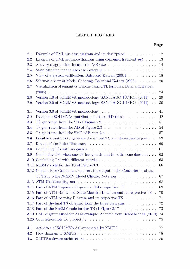
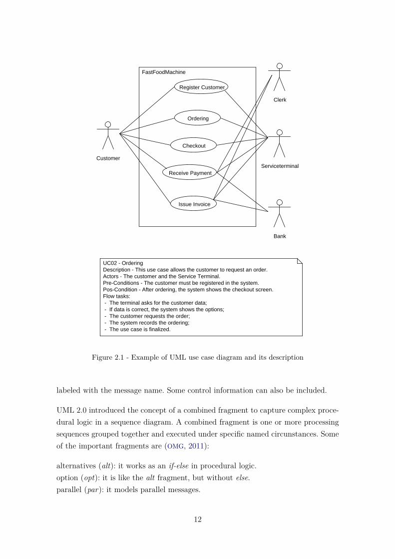
Use cases can be represented by drawing a use case diagram and writing an accom-panying text elaborating the drawing, as can be seen in Figure 2.1. It shows a usecase diagram representing a fast food machine, as well as a description of the usecase Ordering. In this thesis, requirements and properties are extracted from the usecases description or from requirements described in Natural Language.
2.2.2 Sequence Diagram
A sequence diagram describes how groups of objects collaborate on some behaviorover time. It registers the behavior of a single use case and displays objects andmessages passed between these objects in the use case. The sequence diagram followsthe approach based on temporal order of the messages, that is, the emphasis is onthe temporal distribution of messages.
A sequence diagram shows interaction among objects as a two dimensional chart.The chart is read from top to bottom. The objects participating in the interactionare shown at the top of the chart as boxes attached to a vertical dashed line. Thevertical dashed line is called the object’s lifeline. The lifeline indicates the existence ofthe object at any particular point of time. The messages are shown in chronologicalorder from the top to the bottom. That is, reading the diagram from the top tothe bottom would show the sequence in which the messages occur. Each message is
11
FastFoodMachine
Customer
Bank
Clerk
Serviceterminal
Register Customer
Ordering
Checkout
Receive Payment
Issue Invoice
UC02 - OrderingDescription - This use case allows the customer to request an order.Actors - The customer and the Service Terminal.Pre-Conditions - The customer must be registered in the system.Pos-Condition - After ordering, the system shows the checkout screen.Flow tasks:- The terminal asks for the customer data;- If data is correct, the system shows the options;- The customer requests the order;- The system records the ordering; - The use case is finalized.
Figure 2.1 - Example of UML use case diagram and its description
labeled with the message name. Some control information can also be included.
UML 2.0 introduced the concept of a combined fragment to capture complex proce-dural logic in a sequence diagram. A combined fragment is one or more processingsequences grouped together and executed under specific named circunstances. Someof the important fragments are (OMG, 2011):
alternatives (alt): it works as an if-else in procedural logic.option (opt): it is like the alt fragment, but without else.parallel (par): it models parallel messages.
12

loop (loop): it represents the loop in procedural logic.
The fragments alt, opt, and loop have guards which can assume values true or false.Figure 2.2 shows a sequence diagram for the use case Ordering of the fast foodmachine. The messages that are within the combined fragment opt only occur ifthe value of guard data ok is true. Otherwise, only the first and the last messagesare sent. This occurs for all fragments which have guards: the messages within thefragment only are sent if the guard is set with value true.
Customer TerminalService
Register
opt (data ok)
DisplayOptions
ChooseOptions
RecordOrder
DisplayFinalScreen
Figure 2.2 - Example of UML sequence diagram using combined fragment opt
In short, system requirements are represented in the use cases, i.e., use cases modelwhat is the problem. The sequence diagrams show how the model will get thedesired objective. This diagram is constructed from the use cases diagrams, showinginteractions between objects in a scenario.
2.2.3 Activity Diagram
An activity diagram depicts the dynamic behavior of a system (or part of a system)through the flow of control between actions that the system performs (PRESSMAN,
13

2010). It is similar to a flowchart and can show concurrent flows. They evaluate betterthe conditions by which the instances come to certain decisions. It is common tofind definitions of activity diagrams that consider them as flowcharts.
Besides, an activity diagram focuses on representing activities or parts of processingwhich may or may not correspond to the methods of classes. An activity is a statewith an internal action and one or more outgoing transitions which automaticallyfollow the termination of the internal activity. If an activity has more than oneoutgoing transitions, this must be identified through conditions.
Ask customer data
Show products list
data ok
else
Show message: "Ask order?"
Record ordering data
yes
no
Display final screen
Figure 2.3 - Activity diagram for the use case Ordering
14

Activity diagrams can be very useful to understand complex processing activitiesinvolving many components. Later these diagrams can be used to develop interactiondiagrams which help to allocate activities (responsibilities) to classes. They supportdescription of parallel activities and synchronization aspects involved in differentactivities. Main components of such diagrams are (OMG, 2011):
Activities: model the behavior to be performed.Transition: models the flow of an activity to another.Action: models transformation.Decision: depending on a condition, it shows different transitions. Decisions areaccompanied by boolean guards.Fork: it separates a transition in several other transitions that are executed at thesame time.Join: junction of transitions that come from fork.
Figure 2.3 shows an activity diagram for the use case Ordering.
2.2.4 Behavioral State Machine Diagram
Behavioral state machine models an object’s states, the actions that are performeddepending on those states, and the transitions between the states of the objects.They are designed to evaluate the behavior of instances, i.e., the sequence of actionsthat affect the progress of instances, based on a reaction to events. State machinecan be used to specify behavior of various model elements. For example, they canbe used to model the behavior of individual entities (e.g., class instances). The statemachine formalism described is an object-based variant of Harel statecharts (OMG,2011).
Behavioral state machine diagram is also called statechart diagram. In UML, eachclass has an optional state machine that describes the behavior of its instances (theobjects). It is normally used to model how the state of an object changes in itslifetime. Statechart diagrams are good at describing how the behavior of an objectchanges across several use case executions. Statecharts diagrams are based on thefinite state machine (FSM) formalism. This state machine receives events from theenvironment and reacts to them. This diagram specifies the possible states that anobject may assume, the transitions allowed at each state, the events that can causetransitions to occur and the actions that may occur in response to events.
States of an object are essentially determined by the values that certain variables
15

(attributes) of the object may assume. A Statechart is hierarchical model of a systemand introduces the concept of a composite state (also called nested state). Actionsare associated with transitions and are considered to be processes that occur quicklyand are not interruptible. Activities are associated with states and can take longer.An activity can be interrupted by an event.
A transition is shown as an arrow between two states. Normally, the name of theevent which causes the transition is placed along side the arrow. A guard to thetransition can also be assigned. A guard is a boolean logic condition. The transitioncan take place only if the guard evaluates to true. The syntax for the label of thetransition is shown in 3 parts: event[guard]/action.
A state in a statechart diagram can either be simple or composite type. A simplestate, also known as a basic state, does not have any sub-states. A composite state,on the other hand, consists of one or more regions. A region is a container for sub-states. The notion of a composite state makes a statechart model a hierarchicaldiagram. A composite state can either be sequential or concurrent. In a sequentialtype of composite state, the state is considered to be an exclusive-or of its sub-states.That is, a composite state can be in any one of its sub-states, but not in more thanone sub-state at any time. But, in a concurrent type, the state is determined by anand logic of its sub-states and the object is considered to be in all the concurrentstates at the same time. Figure 2.4 shows an example of Behavioral State Machinefor the use case Ordering. It is possible to see a composite state (Serving customer).
Activity X Behavioral State Machine
Both state machine and activity diagrams are state machines. Any state machineaims to assess the dynamic aspects of a system model and the following elementsare always identified: states, inputs, outputs, transitions, an initial state, and a finalstate (MATOS, 2002).
Both activity and Statechart diagrams model the dynamic behavior of the system.Activity diagram is essentially a flowchart showing flow of control from activity toactivity. A statechart diagram shows a state machine emphasizing the flow of controlfrom state to state.
Activity diagrams may stand alone to visualize, specify, and document the dynamicsof a society of objects or they may be used to model the flow of control of an oper-ation. Statechart diagrams may be attached to classes, use cases, or entire systems
16

Idle
Validating Data
Displaying Options
Serving Customer
Registering Order
Back
DataEntry
InvalidData
Figure 2.4 - State Machine for the use case Ordering
in order to visualize, specify, and document the dynamics of an individual object.
2.3 Formal Verification Methods
Formal Verification refers to mathematical analysis of proving or disproving the cor-rectness of a hardware or software system with respect to a certain specification orproperty (GANAI; GUPTA, 2007). Formal Verification constructs mathematical proofsabout the behavior of computer hardware or software, and has strong connectionswith theoretical computing. The methods for analysis are known as Formal Veri-fication Methods and they can be broadly classified into: Theorem Proving andModel Checking. Both are explained in the next sections.
The properties to be validated are mainly obtained from the system’s specification.The specification describes what the system has to do and what not, and thus canbe used as basis for any verification activity. A defect is found if the system doesnot satisfy one of the specification’s properties. The system is said to be “correct”
17

whenever it satisfies all properties obtained from its specification. Therefore, cor-rectness is relative to a specification, and is not an absolute property of a system(BAIER; KATOEN, 2008). A view of verification is presented in Figure 2.5.
Figure 2.5 - View of a system verification. Baier and Katoen (2008)
Model-based verification techniques are based on models describing the possiblesystem behavior in a mathematically precise and unambiguous manner. The systemmodels are accompanied by algorithms that systematically explore all states of thesystem model. This provides the basis for a whole range of verification techniquessuch as exhaustive exploration (Model Checking) to experiments with a restrictiveset of scenarios in the model (simulation), or in reality (testing) (BAIER; KATOEN,2008). The next section gives a brief description of Theorem Proving.
2.3.1 Theorem Proving
Theorem Proving is a proof-based approach to Formal Verification. In this method,the system that is being analyzed is modelled as a set of mathematical definitionsusing formal mathematical logic. The desired properties of the system are derivedas theorems that follow from these definitions (AMJAD, 2004). There is a need toprove theorems in order to establish mathematical theorems, as well as in order toestablish the correctness of software and hardware.
According to (SETZER, 2008) there are four ways of Theorem Proving:
a) Theorem Proving by hand: this is what mathematicians do all the time.As it is very human-dependent, there is the problem of errors and it is
18

unsuitable for verifying large software and hardware systems;
b) Theorem Proving with some machine support: machine checks the syn-tax of the statements, creates a good layout, translates it into differentlanguages, but Theorem Proving is still done by hand;
c) Interactive Theorem Proving: proofs are fully checked by the system. How-ever, proof steps have to be carried out by the user;
d) Automated Theorem Proving: the theorem is shown by the machine. It isthe task of the user to state the theorem, bring it into a form so that itcan be solved.
Techniques have been developed to automate the process of derivation or proof, byusing computers. Theorem provers use mathematical reasoning and logical inferenceto prove the correctness of systems, and often require a specialist with substantialunderstanding of the system under verification (BAIER; KATOEN, 2008).
The advantage of proof-based approach is that it can handle complex systems be-cause it does not have to directly check each and every state. The disadvantage isthat it requires human insight and creativity to complete the proofs, which requirestime-consuming manual labour (AMJAD, 2004).
The other Formal Verification method discussed in the present work is Model Check-ing (CLARKE; EMERSON, 2008) (QUEILLE; SIFAKIS, 1982). Model Checking is a For-mal Verification method that starts from a formal system specification. It is detailedin the following section.
2.3.2 Model Checking
Model Checking is a method that is executed automatically to verify if a model ofa system meets certain specifications. According to Baier (BAIER; KATOEN, 2008),“Model Checking is an automated technique that, given a finite-state model of asystem and a formal property, systematically checks whether this property holds for(a given state in) that model”.
In design of complex systems, large time and effort are spent on V&V. Techniquesare developed to reduce and ease the V&V efforts while increasing their coverage.During the last decades, research in Formal Methods has led to the developmentof some very promising verification techniques that facilitate the early detection
19

of defects. Investigations have shown that Formal Verification procedures wouldhave revealed the exposed defects in, e.g., the Ariane-5 missile, Mars Pathfinder,Intel’s Pentium II processor, and the Therac-25 therapy radiation machine (BAIER;
KATOEN, 2008).
Model Checking is a verification technique that explores all possible system states ina brute-force manner. The software tool that performs the Model Checking, examinesall possible system scenarios in a systematic manner. Hence, it can be proved thata given system model truly satisfies a determined property. Baier (BAIER; KATOEN,2008) states that “even the subtle errors that remain undiscovered using emulation,testing and simulation can potentially be revealed using Model Checking”. However,it is a challenge to examine all possible state spaces.
The Model Checking approach can be viewed in Figure 2.6. There are propertiesobtained from the requirements that reveals what the system should do and not todo. The properties are formalized using some sort of temporal logic such as LinearTemporal Logic (LTL) or Computation Tree Logic (CTL). A model is generatedusually from the system’s pseudocode and describes the behavior of the transitionsystem (finite-state model). The model checker examines all relevant system statesto check whether they satisfy the desired property. If a state violates the propertyunder consideration, the model checker provides a counterexample showing a tracethat indicates the violation.
Figure 2.6 - Schematic view of Model Checking. Baier and Katoen (2008)
20

Model Checking Process
In applying Model Checking to a design, the following different phases can be dis-tinguished:
• Modeling phase:
– model the system under consideration using the model descriptionlanguage of the model checker at hand;
– formalize the property to be checked using the property specificationlanguage.
• Running phase: run the model checker to check the validity of the propertyin the system model.
• Analysis phase:
– property satisfied? So check next property (if any);
– property violated?
a) analyze generated counterexample;b) refine the model, design, or property;c) repeat the entire procedure.
– out of memory? So try to reduce the model and try again.
The next subsection explains some issues on properties and their formalization usingtemporal logic, once Model Checking requires formalized properties using LTL orCTL.
2.3.2.1 Temporal Logic and Properties
Before going into detail about temporal logic, it is important to show the mean-ing and notation of the logical connectives, temporal modalities (operators), andpath quantifiers. Table 2.1 shows the notation and meaning of each one. Temporalmodalities (operators) and path quantifiers are further discussed in more details.
The semantics of propositional logic is specified by a satisfaction relation |= indi-cating the evaluations µ for which a formula Φ is true. It is written as:
µ |= Φ
21
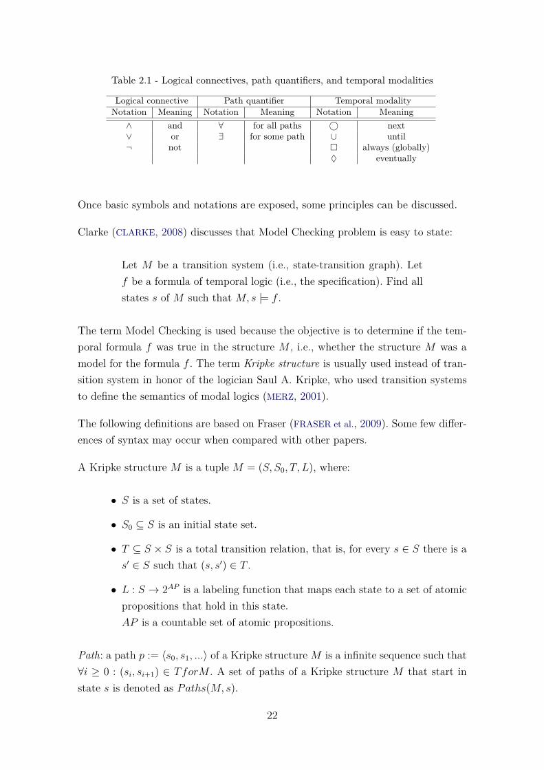
Table 2.1 - Logical connectives, path quantifiers, and temporal modalities
Logical connective Path quantifier Temporal modalityNotation Meaning Notation Meaning Notation Meaning∧ and ∀ for all paths © next∨ or ∃ for some path ∪ until¬ not � always (globally)
♦ eventually
Once basic symbols and notations are exposed, some principles can be discussed.
Clarke (CLARKE, 2008) discusses that Model Checking problem is easy to state:
Let M be a transition system (i.e., state-transition graph). Letf be a formula of temporal logic (i.e., the specification). Find allstates s of M such that M, s |= f .
The term Model Checking is used because the objective is to determine if the tem-poral formula f was true in the structure M , i.e., whether the structure M was amodel for the formula f . The term Kripke structure is usually used instead of tran-sition system in honor of the logician Saul A. Kripke, who used transition systemsto define the semantics of modal logics (MERZ, 2001).
The following definitions are based on Fraser (FRASER et al., 2009). Some few differ-ences of syntax may occur when compared with other papers.
A Kripke structure M is a tuple M = (S, S0, T, L), where:
• S is a set of states.
• S0 ⊆ S is an initial state set.
• T ⊆ S × S is a total transition relation, that is, for every s ∈ S there is as′ ∈ S such that (s, s′) ∈ T .
• L : S → 2AP is a labeling function that maps each state to a set of atomicpropositions that hold in this state.AP is a countable set of atomic propositions.
Path: a path p := 〈s0, s1, ...〉 of a Kripke structureM is a infinite sequence such that∀i ≥ 0 : (si, si+1) ∈ TforM . A set of paths of a Kripke structure M that start instate s is denoted as Paths(M, s).
22

As infinite paths are not usable in practice, Model Checking uses finite sequences,commonly referred to as traces. The number of transitions in a trace is referred toas its length. For example, trace t := 〈s0, s1, ..., sn〉 has a length of length(t) = n.
Temporal logic describes the ordering of events in time without introducing timeexplicitly. The meaning of a temporal logic formula is determined with respect to aKripke structure. Most temporal logics have an operator like �f that is true in thepresent if f is always true in the future. Temporal logic is often classified accordingto whether time is assumed to have a linear or a branching structure. A lineartime LTL assertion h is interpreted with respect to a single path. An assertion of abranching time logic is interpreted over computation trees.
2.3.2.1.1 Linear Temporal Logic (LTL)
An LTL formula consists of atomic propositions, boolean operators and temporaloperators. The operator “©” refers to the next state. So, “© a” expresses that ahas to be true in the next state. “∪” is the until operator, where “a∪ b” means thata has to hold from the current state up to a state where b is true. “�” is the alwaysoperator, stating that a condition has to hold at all states of a path, and “♦” isthe eventually operator that requires a certain condition to eventually hold at sometime in the future.
If a property φ is satisfied by the path π of model M , this is denoted by “M,π �
φ” and “M,π 2 φ” expresses that the property is not satisfied by the path. Thesemantics of LTL is expressed for infinite paths of a Kripke structure. πi denotesthe suffix of the path π starting from the i-th state, and πi denotes the i-th state ofthe path π. The initial state of a path π is π0.
2.3.2.1.2 Computation Tree Logic (CTL)
CTL formulas are similar to LTL but with an extra element, path quantifiers. Thepath quantifiers ∀ (for all) and ∃ (there exists) require formulas to hold on all orsome paths, respectively. A schematic view of the validity of ∃�, ∃♦, ∀♦, and ∀� isgiven in Figure 2.7, where black-colored states satisfy the proposition black.
As all temporal operators are preceded by a path quantifier in CTL, the semantics ofCTL can be expressed by satisfaction relations for state formulas. M, s � φ denotesa state formula φ that is satified in state s of Kripke structure M . Most modelcheckers use either CTL or LTL in practice, as there are some formulas that can beonly formalized in CLT, and vice-versa.
23

Figure 2.7 - Visualization of semantics of some basic CTL formulae. Baier and Katoen(2008)
2.3.2.1.3 Properties
Commonly, three different types of verifiable properties are distinguished:
Safety Property: A safety property describes a behavior that may not occur on anypath (“Something bad may not happen”). To verify a safety property, all executionpaths have to be checked exhaustively. Safety properties are of the type �¬φ or∀�¬φ, where φ is a propositional formula. Examples of safety property: mutualexclusion property (always at most one process is in its critical section) and deadlockfreedom.
Invariance Property: An invariance property describes a behavior that is requiredto hold on all execution paths. It is logically complementary to a safety property.Invariance properties are of the type �φ or ∀�φ, where φ is a propositional formula.
Liveness Property: A liveness property describes that “something good eventuallyhappens”. With linear time logic, this means that a certain state will always bereached. For example, �φ1 → ♦φ2 and ∀(� φ1 → ∀♦ φ2) are liveness properties.
Dwyer (DWYER et al., 1999) proposed a system of property specification patternsfor finite-state verification. They proposed 8 patterns and 5 pattern’s scopes. Hence,
24

based on a requirement, one identifies a pattern and the scope within the patternthat mostly characterize such requirement. Having decided which is the patternand scope they proposed a template to generate the properties in LTL, CTL, andQuantified Regular Expressions. For instance, some descriptions of pattern/patternscope are presented below with the correponding CTL state formulae (SANTIAGO
JÚNIOR, 2011):
a) Absence Pattern and Globally Scope: a given state/event p does notoccur within the entire program/model execution. CTL formula: ∀�¬p;
b) Response Pattern and Globally Scope: a state/event p must alwaysbe followed by a state/event q within the entire program/model execution.CTL formula: ∀�(p→ ∀♦q);
c) Precedence Pattern and Globally Scope: a state/event p must alwaysbe preceded by a state/event q within the entire program/model execution.CTL formula: ¬∃[¬q ∪ (p ∧ ¬q)].
The Absence Patern and Globally Scope is indeed a safety property which is oftencharacterized as “nothing bad should happen”. In the above descriptions, the sen-tence “a given state/event occurs” means “a state in which the given state formulais true, or an event from the given disjunction of events occurs” (SANTIAGO JÚNIOR,2011).
The aim of Model Checking is to determine if a given model fulfills a property.Several different algorithms have been successfully used for this task, using differenttemporal logics and data structures. Once property violation or satisfaction is deter-mined, a model checker can return an example of how this violation or satisfactionoccurs. This is illustrated with a counterexample in the case of violation, or witnessin the case of satisfaction (FRASER et al., 2009). Satisfaction of LTL properties is de-fined using linear sequences. Consequently, witnesses and counterexamples for LTLformulas are also linear sequences. In contrast, CTL properties are state formulas.Therefore, the CTL Model Checking problem is to find the set of states that satisfya given formula in a given Kripke structure (FRASER et al., 2009). Special algorithmsare used to derive trace examples for witness or counterexample states.
2.3.2.2 NuSMV
There is a wide range of available tools for applying Model Checking, for instance,SPIN (HOLZMANN, 2004), NuSMV (KESSLER, 2015), UPPAAL (BEHRMANN et al.,
25

2004), and JavaPathfinder (NASA, 2015). NuSMV is open, flexible, and documentedplatform. NuSMV was previously used in version 2.0 of SOLIMVA methodology andit is also used in this PhD thesis. Following, a discussion is presented to show anoverview of the NuSMV syntax.
The NuSMV language allows the description of finite state models. Finite statemodels consist of a set of variables and predicates on these variables. Predicates usethe logical operators & (and), | (or), and ! (not). Constant 1 denotes true whereas0 denotes false. Variables are declared using the VAR keyword, followed by a list oftyped variable declarations. Variables can be of type boolean or can be enumerative.For example,
VARaa b : boolean;aa a : { a1,a2,a3 };
declares a boolean variable b and a variable a that has an enumerative type, i.e.,the value of a is either a1, a2, or a3.
There are basically two kinds of predicates: predicates defining the initial stateand predicates defining the transition relation, relating the current values of somevariables with their possible next values. A state is an assignment of values to a setof variables. Predicates defining the initial state are preceded by the INIT keyword.If there is more than one INIT declaration, the initial state is characterized by theconjunction of all the INIT predicates.
Predicates defining the transition relation can be defined using assignment dec-larations for each variable. Assignments are preceded by the ASSIGN keyword. Inassignments, next(v) refers to the next value of variable v. If different next valuesare possible, depending upon some current condition, the case construct is used. Thelist of case expressions is evaluated sequentially, starting at the top. For example,
ASSIGNaa next(b):=aaaa case(b)aaaaaa !b: 1;aaaaaa 1: 0;aaaa esac;
says that the next value of b will be true if b is currently false, and false otherwise.
26

All assignments are made concurrently, i.e., all variables change value at the sametime. Two concurrent assignments to the same variable are forbidden.
The main purpose of a model checker is to verify that a model satisfies a set of desiredproperties specified by the user. Table 2.2 shows how temporal logic elements canbe expressed in NuSMV input language.
Table 2.2 - Logical connectives, path quantifiers, and temporal modalities expressed inNuSMV notation
Logical connective Path quantifier Temporal modalityNotation Meaning Notation Meaning Notation Meaning
& and A for all paths X next| or E for some path U until! not G always (globally)
F eventually
Basically, these are the main points related to the NuSMV syntax that are relevantto this PhD thesis.
2.3.2.3 Strengths and Weaknesses
A set of strengths and weaknesses of Model Checking have been exhibited in Baier(BAIER; KATOEN, 2008). It is shown those that are considered relevant for this thesis.
Strengths:
a) It is a general verification approach, applicable to a wide range of ap-plications such as embedded systems, software engineering, and hardwaredesign.
b) It supports partial verification, i.e., properties can be checked individually,thus allowing focus on the essential properties first.
c) It is not vulnerable to the likelihood that an defect is exposed; this contrastswith testing and simulation that are aimed at tracing the most probabledefects.
d) It provides diagnostic information in case a property is invalidated; this isvery useful for debugging purposes.
Weaknesses:
27

a) It suffers from the state-space explosion problem, i.e., the number of statesneeded to model the system accurately may easily exceed the amount ofavailable computer memory.
b) Its usage requires some expertise in finding appropriate abstractions to ob-tain smaller system models and to state properties in the logical formalismused.
In summary, Model Checking can not be applied in some areas, such as systemswith a great number of components. However, it can suggest results for arbitraryparameters that may be verified using proof assistants, and therefore it has beenused in a broad range of systems.
2.4 SOLIMVA 1.0 and 2.0 Methodologies
This section aims to give an overview of the SOLIMVA methodology (SANTIAGO
JÚNIOR, 2011) (SANTIAGO JÚNIOR; VIJAYKUMAR, 2012) versions 1.0 and 2.0. Ver-sion 1.0 of the SOLIMVA methodology aims at the generation of model-based systemand acceptance test cases considering Natural Language (NL) requirements deliver-ables. The SOLIMVA is supported by a main tool, also called SOLIMVA, that makesit possible to automatically translate NL requirements into Statechart models. Oncethe Statecharts are created, the Geração Automática de Casos de Teste Baseada emStatecharts (GTSC - Automated Test Case Generation based on Statecharts) (SAN-
TIAGO et al., 2008),(SANTIAGO JÚNIOR et al., 2012) environment is used to generateAbstract Test Cases which are later translated into Executable Test Cases.
Version 1.0 of the SOLIMVA methodology is illustrated in the activity diagramof Figure 2.8. The first activity is the definition of a Dictionary by the user/testdesigner. The Dictionary defines the application domain. After the definition of theDictionary, scenarios are identified. A scenario is defined as an interaction between auser and the Implementation Under Test (IUT). Associated with each scenario thereis a set of requirements which characterize such an interaction. After the previoussteps, the user must select and input a set of NL requirements. The user must searchthese requirements in documents such as software requirements specifications.
The Dictionary does not necessarily have to be defined completely at once. Thisis shown as the optional activity Update Dictionary. Hence, the creation of theDictionary is incremental and dependent on the selected set of NL requirements.After that, the generation of the Statechart model follows. After generating the
28

Define and Input Dictionary
Define Scenarios
Select and Input NL Requirements
Generate Model
Clear Requirementsand Model [manual refinement]
Generate Abstract Test Cases
Generate Executable Test Cases
[more scenarios]
[else]
Update Dictionary[dictionary update]
[else]
[end of scenarios]
Figure 2.8 - Version 1.0 of SOLIMVA methodology. SANTIAGO JÚNIOR (2011)
model, the test designer may decide to manually refine it.
After these steps, Abstract Test Cases are generated by using the GTSC environ-ment. GTSC allows test designers to model software behavior using Statechartsand/or FSMs in order to automatically generate test cases based on some test cri-teria for FSM and some for Statecharts. Then, the test designer shall accomplishthe translation from Abstract Test Cases into Executable Test Cases to enable theeffective execution of test cases.
Having created the test cases (Executable Test Cases) for a single scenario, thetest designer starts again selecting and inserting the NL requirements for the nextscenario. But before doing this, he/she must clear the requirements and relatedmodel of the current scenario. This process must be repeated until there is no more
29
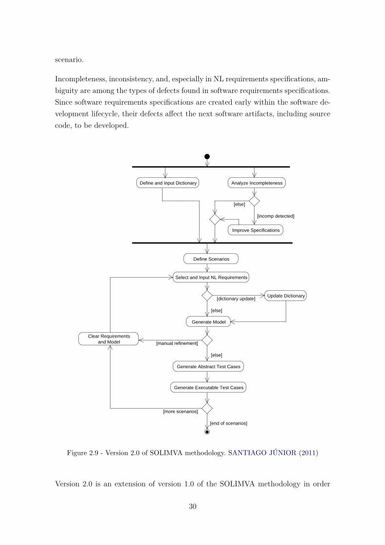
scenario.
Incompleteness, inconsistency, and, especially in NL requirements specifications, am-biguity are among the types of defects found in software requirements specifications.Since software requirements specifications are created early within the software de-velopment lifecycle, their defects affect the next software artifacts, including sourcecode, to be developed.
Define and Input Dictionary
Define Scenarios
Select and Input NL Requirements
Generate Model
Clear Requirementsand Model [manual refinement]
Generate Abstract Test Cases
Generate Executable Test Cases
[more scenarios]
[else]
Update Dictionary[dictionary update]
[else]
Analyze Incompleteness
Improve Specifications
[incomp detected]
[else]
[end of scenarios]
Figure 2.9 - Version 2.0 of SOLIMVA methodology. SANTIAGO JÚNIOR (2011)
Version 2.0 is an extension of version 1.0 of the SOLIMVA methodology in order
30

to address the goal of detecting incompleteness in software specifications (SANTI-
AGO JÚNIOR, 2011). Model Checking combined with k-permutations of n values ofvariables and specification patterns (DWYER et al., 1999) were used to tackle thisproblem. The new version is shown in Figure 2.9. The new activities are AnalyzeIncompleteness and Improve Specifications. The activities present in version 1.0 arealso present in version 2.0, and the workflow is essentially the same. The only dif-ference is that the execution of these new activities should proceed in parallel withthe Define and Input Dictionary activity.
The most important activity to deal with the problem of incompleteness is Ana-lyze Incompleteness. It is by means of this activity that incompleteness defects aretruly detected. It is important to realize that Model Checking, in version 2.0 of theSOLIMVA methodology, was used as a tool to aid the software inspection process(detection of incompleteness in software specifications) and not as in the more tradi-tional approach where the finite-state model is verified against formalized propertiesto realize whether the behavior of the system meets its specifications. Once incom-pleteness defects are detected, the quality of the assessed software specifications canbe improved by completing the documents, when necessary. This is the ImproveSpecifications activity.
2.5 Formal Verification and UML
This section presents some of the research literature related to this PhD thesis,showing approaches that made efforts on the use of Formal Verification and UMLwith diverse purposes. Table 2.3 summarizes the main characteristics of the referredpublished literature.
Sarma and Mall (SARMA; MALL, 2009) proposed a system testing approach to coverelementary transition paths. The technique consisted on derivation of a System StateGraph (SSG) based on UML 2.0 use case models, sequence diagrams, and Statechartmodels to design system test specifications to achieve coverage of system statesand transitions among them. They aim to satisfy the test criterion transition pathcoverage. Even though it is related to Software Test instead of Formal Verification,this research was very helpful for the present work because they use the conceptof scenarios and explore the relation between sequence and statechart diagrams,which was quite motivating for this PhD thesis. The importance of UML models indesigning test cases is recognized in several other investigations, such as (BRIAND;
LABICHE, 2002), (HARTMANN et al., 2005), (CHEN et al., 2008), (BRITO et al., 2009),(KIM et al., 1999), and (RIEBISCH et al., 2003). However, all these works used UML
31

to somehow generate test cases. In the present research, the interest is in UML andFormal Verification.
Mikk (MIKK et al., 1998) translated Statecharts into PROMELA, the input lan-guage of the SPIN verification system. They used extended hierarchical automataas an intermediate format. The conclusion demonstrates the feasibility of LTL ModelChecking for statecharts. Latella (LATELLA et al., 1999) showed a translation froma subset of UML Statechart Diagrams - covering essential aspects of both con-current behaviour, like sequentialization, parallelism, non-determinism and priority,and state refinement - into PROMELA. Both works used Statecharts to performthe translation into PROMELA language. They use one single UML diagram, theStatechart.
In (ANDERSON et al., 1996), Anderson translates the specification of TCAS (Traf-fic Alert and Collision Avoidance System), which is specified in RSML (Require-ments State Machine Language) into the input language of NuSMV. The objectivewas to investigate if Model Checking could be used in large software specifications.Dubrovin (DUBROVIN; JUNTTILA, 2008) implemented a tool that translates UMLhierarchical state machine models to the input language of NuSMV too. They havedefined a semantics and a compact symbolic encoding for a class of UML modelswhich are basically hierarchical state machine. Uchitel (UCHITEL; KRAMER, 2001)proposes translation of scenarios, specified as Message Sequence Charts (MSCs),into a specification in the form of Finite Sequential Processes. This can then befed to the Labelled Transition System Analyser model checker to support systemrequirements validation.
Lam (LAM, 2007) examined how activity diagrams defined in UML 2.0 standardare formally analyzed using NuSMV model checker. A model represented as activitydiagrams is first transformed into NuSMV input language and then verified that aset of system specifications is satisfied using NuSMV. The objective was determiningthe correctness of activity diagrams.
Eshuis (ESHUIS, 2006) presented two translations from activity diagrams to theinput language of NuSMV. Both translations map an activity diagram into a fi-nite state machine (FSM) and are inspired by existing Statechart semantics. Therequirements-level translation defines state machine that can be efficiently verified,but they assume the perfect synchrony hypothesis. The implementation-level trans-lation defines state machine that cannot be verified so efficiently, but that are morerealistic since they do not use the perfect synchrony hypothesis. The aim was to
32

assess the activity diagrams from the point of view of requirements and also fromthe point of view of implementation, which represents the actual system behavior.These two last research works, also used one single diagram, the activity diagram.
Konrad and Cheng (KONRAD; CHENG, 2006) presented a process that supports thespecification and analysis of UML models wih respect to behavioral properties spec-ified in NL. This process has been implemented using the SPIDER tool. This ap-proach is a Model Checking of UML models against NL properties. UML modelsare read and formal specification language PROMELA for the model checker SPINis generated. NL properties are derived using a previous work (KONRAD; CHENG,2005), where a grammar was developed. The grammar enables the NL representa-tion of specification patterns, and it is used to formalize properties in LTL. The aimis to check UML models against the NL properties (requirements). Hence, the focusof their work is checking NL requirements. On the other hand, the present workfocuses on checking UML models. They use version 1.4 of UML.
All the investigations presented so far, related to UML and Formal Verification, dealwith a single UML or UML-like diagram to perform Formal Verification. Rather,the present research allows to work with up to three UML behavioral diagrams.In addition, it is not clear if in the previous studies the authors used specificationpatterns to formalize the properties. Specification patterns provide clear guidelinesto such formalization. The present work is proposing a full approach to detect defectsin the design of software developed in accordance with UML. In addition, it alsowas developed a tool to translate UML diagrams into a unified TS to support ModelChecking.
Schäfer (SCHÄFER et al., 2001) and Knapp (KNAPP; MERZ, 2002) used two comple-mentary UML notations for the specification of dynamic system behavior - statemachine and collaborations - to automatically verify whether the interactions ex-pressed by a collaboration can indeed be accomplished by a set of state machines.The first used the model checker SPIN to verify the model against the automatawhile the second used the model checker UPPAAL to perform the same task. Bothworks aim to validate the two diagrams, applying consistency checking betweendiagrams.
Calinescu (JOHNSON et al., 2013) used a probabilistic model checker (PRISM) toverify critical systems, after changes. Verifying these software systems only at designtime is insufficient, they have to be reverified after each change. They did not workwith UML diagrams, but with components and deterministic finite automata.
33

Cortellessa (CORTELLESSA; MIRANDOLA, 2002) suggested an interesting approachto encompass performance validation task as an integrated activity within the de-velopment process. They propose a methodology called Performance IncrementalValidation in UML (PRIMA-UML) aimed at generating a queueing network basedperformance model from UML diagrams that are usually available early in the soft-ware lifecycle (use case, sequence, and deployment). Bernardi (MERSEGUER et al.,2002) translated sequence and statechart diagrams into Generalized Stochastic PetriNets. Both works aimed analyzing performance aspects of systems. The present re-search is related to functional aspects of the software product, aiming at detectingdesign defects within the solution, but considering exclusively functional require-ments of the software product.
To the best of our knowledge, only three studies consider the translation from sev-eral UML or UML-like diagrams into a formal notation to perform validation ofUML diagrams, aiming functional requirements. Baresi (BARESI et al., 2011) devel-oped MADES, a tool to carry out Formal Verification of UML-based models, mainlyinterested in the timing aspects of systems. It is composed by: static part (class di-agrams); dynamic aspects and behavior are rendered through: (a) state diagramsand activity; (b) sequence diagrams; and (c) interaction overview diagrams, usedto relate different sequence diagrams; Clocks (and time diagrams) are used to addthe time dimension to systems. All these diagrams seem to be required to constructthe approach. However, this assorted number of diagrams is not always available inthe documentation. Adversely, this proposal requires only one diagrama as manda-tory (the sequence diagram), which provides a higher chance of being used in realapplications.
In (MIYAZAWA et al., 2013), a proposal of a formal semantics of SysML based on theCOMPASS Modeling Language (CML) (WOODCOCK et al., 2012) notation is pre-sented. The semantics of SysML is given as a translation from the abstract syntaxof SysML to the abstract syntax of CML. They addressed the translation to CMLof model that include several structural and behavioral SysML diagrams: block def-inition diagrams, internal block diagrams, activity diagrams, sequence diagrams,and state machine diagrams. The basic difference between the present work andtheirs is that we translate the behavioral diagrams to the input language of NuSMVand not to CML. A context-free grammar that guide the derivation of the code inNuSMV was defined, with a very simple structure making it easier to undestandthe translation. Also, they translate SysML diagrams, which has distinctive featuresfrom UML. Moreover, it is not clear if their approach has been applied to real and
34
complex case studies as it was done in this PhD thesis.
Encarnación Beato (BEATO et al., 2005) presents a tool (TABU - Tool for the ActiveBehaviour of UML) to convert three UML diagrams into a SMV input for FormalVerification: class, state and activity diagrams. It seems to see a close approachto the present solution, using a tool for convert the XMI inputs into a SMV file.The difference is in the use of Cadence SMV as a Formal Verification tool and theneed to use all the diagrams to get an output. Besides, the present research worksexclusively with behavioral diagrams, while they use class diagram.
The main motivation of this approach is the practical use of formal methods insoftware development, through automation. This can be done throughout the life-cycle, even before software coding. Besides, the present research suggests to get asingle vision of the system captured from three different diagrams (sequence, activ-ity, and behavioral state machine). These diagrams represent complementary viewsof system behavior and are often used in different phases of software specificationand design, allowing thus a wider system range to be verified. Most of the worksmentioned deal with a specific type of UML diagram.
Another important difference of the present research related to the others is that eventhough there are works which use various UML diagrams, the checking is performedon individual diagrams. None of them seems to use an unified model to perform theverification, as the present research does.
A comparison between the most relevant studies related to this PhD thesis is shownin Table 2.3. The table shows the research objectives (Software Testing or FormalVerification), the type of requirements that is being analyzed in the research (func-tional or non-functional), and also if the research uses one single UML diagram orvarious UML diagrams, as well as if the diagrams are structural or behavioral.
35

Table2.3-C
ompa
rison
betw
eenthemostrelevant
research
relatedto
SOLIMVA
3.0
Research
UML
Softw
are
Form
alFu
nctio
nal
Non
-functio
nal
One
single
Vario
usStructural
Behavioral
Testing
Verifi
catio
ndiagram
diagrams
(SA
RM
A;M
ALL
,2009)
XX
XX
X(B
RIA
ND
;LA
BIC
HE,2
002)
XX
X(H
AR
TM
AN
Net
al.,2005)
(CH
EN
etal
.,2008)
(BR
ITO
etal
.,2009)
(KIM
etal
.,1999)
(RIE
BIS
CH
etal
.,2003)
(MIK
Ket
al.,1998)
XX
XX
(LA
TE
LLA
etal
.,1999)
XX
XX
(AN
DE
RSO
Net
al.,1996)
XX
XX
(DU
BR
OV
IN;J
UN
TT
ILA,2
008)
XX
XX
(UC
HIT
EL;
KR
AM
ER,2
001)
XX
XX
(LA
M,2
007)
XX
XX
(ESH
UIS,2
006)
XX
XX
(KO
NR
AD
;CH
EN
G,2
006)
XX
XX
(KO
NR
AD
;CH
EN
G,2
005)
(SC
HÄ
FE
Ret
al.,2001)
XX
XX
(KN
AP
P;M
ER
Z,2002)
XX
XX
(CO
RT
ELL
ESS
A;M
IRA
ND
OLA
,2002)
XX
XX
X(M
ER
SEG
UE
Ret
al.,2002)
XX
XX
(BA
RE
SIet
al.,2011)
XX
XX
X(M
IYA
ZAW
Aet
al.,2013)
XX
XX
X(B
EA
TO
etal
.,2005)
XX
XX
XSO
LIMVA
3.0
XX
XX
36

2.6 Final Remarks
This chapter presented the theory and research related to this PhD thesis. The areasof knowledge associated with the present research include UML, Formal Verification,Model Checking, Temporal Logic, SOLIMVA 1.0 and 2.0 methodologies, amongothers. The chapter presented only the information necessary for understanding thisthesis, as all these areas are very large and complex.
It also was presented works related to this PhD thesis, always trying to emphasizetheir main differences related to the present research. Table 2.3 summarizes the maincharacteristics of the studies. Some investigations have the objective of applyingSoftware Testing instead of Formal Verification. This thesis keep the idea of usingmultiple behavioral UML diagrams, representing complementary views of the systembehaviors. The goal of the present work is to let the user free to use any number ofthe three accepted diagrams (with at last one sequence diagram when working withmore than one diagram). Most of the tools mentioned seems to work with a onlydiagram at time or multiple required diagrams as input.
The next chapter presents SOLIMVA 3.0 methodology, the proposed solution forModel Checking UML-based software. The activities that make up the methodologyare explained. It also is detailed how the unified TS is obtained and translated to themodel checker notation. For better understanding, a running example is presented.
37


3 APPROACH TO APPLY FORMAL VERIFICATION TO UML-BASED SOFTWARE
This chapter presents SOLIMVA 3.0 methodology aiming to address the objectivestated in Chapter 1: to transform a non-formal language (UML) to a formal language(language of a model checker) in order to detect defects within the design of thesoftware product. An abridged version of this chapter can be seen in (SANTOS et al.,2014a).
Literature review has shown the wide adoption of UML to the design and modelingof object-oriented software and that UML has received attention from researchers, aswell as practitioners (SARMA; MALL, 2009). UML is popular not only for designingand documenting systems, but its importance is being recognized in providing waysto allow the application of Validation and Verification techniques (SARMA; MALL,2009) (KNAPP; MERZ, 2002) (SCHÄFER et al., 2001) (MIKK et al., 1998) (BRITO et al.,2009) (ANDERSON et al., 1996) (DUBROVIN; JUNTTILA, 2008) (BARESI et al., 2011),among others. UML diagrams can be used to capture different views of a system,such as users’, structural, behavioral, implementation, and environmental (OMG,2011). This thesis used the UML behavioral view.
As the basis of this research, it is considered that professionals specify the func-tionality of the system with use cases. In the case of use cases descriptions are notavailable, properties are obtained from requirements described in Natural Language.Each use case is detailed (at least, it should be) by a set of UML sequence diagrams.For each use case, there should exist at least one sequence diagram that representsand describes its main scenario.
This strategy as an extension of SOLIMVA methodology is explained in the nextsection. The rest of the chapter is as follows: Section 3.2 describes the transformationof UML diagrams into Transition Systems. Section 3.3 shows how to obtain theNuSMV notation from the unified TS. In Section 3.4, a running example is presentedfor a better understanding of the methodology. Final remarks are in Section 3.5.
3.1 The SOLIMVA 3.0 Methodology
As presented in Section 2.4, version 1.0 of the SOLIMVA methodology aims atmodel-based test case generation considering NL requirements deliverables. Version1.0 of the SOLIMVA methodology was later extended to address the detection ofincompleteness in software specifications. This generated version 2.0 of SOLIMVA
39

and, therefore, the new activities of version 2.0 of the methodology are more relatedto the automation of software inspection, specifically for detecting defects in softwarespecifications (SANTIAGO JÚNIOR, 2011).
Testing and Formal Verification are best considered as complementary techniques.While Formal Verification techniques aim at showing that a given program/systemsatisfies certain formalized properties or that a proof-based approach to correctnessis followed, testing aims to show that the given program is reliable in that no defectsof any significance were found (MARTHUR, 2008). In this context, this research isintended to improve the existing SOLIMVA methodology to address not only soft-ware testing and inspection, but also Formal Verification in the more traditionalapproach.
Version 3.0 of the SOLIMVA methodology is illustrated in the activity diagram ofFigure 3.1. The contribution of this PhD thesis is encompassed by the dashed lines inred. It is worth mentioning that the same activities, with the same features, presentin version 2.0 of the SOLIMVA methodology are also present in version 3.0, as wellas the workflow, that is the same. The difference is that it is possible to execute thenew activities of version 3.0 of the SOLIMVA methodology in parallel with the olderactivities. In practical terms, version 3.0 of SOLIMVA proposes that the activitiesof testing/inspection and Formal Verification can be performed independently bydifferent teams and even at different phases of the software development lifecycle.
Figure 3.2 shows in detail the contribution of this PhD thesis so that Formal Verifi-cation can now be addressed by SOLIMVA. In figure 3.2, activities which are shownin dashed line have been automated by the XMITS tool. XMITS is explained inthe next chapter. In the following, the activities of the SOLIMVA 3.0 methodology(SANTOS et al., 2014a) are explained:
a) Identify Scenarios. As mentioned earlier, in this work, verification con-sists of sequence of scenarios to be checked. Basically, scenarios focus onhow the system behaves to implement its functionalities. A scenario is asequence of events expected during the system operation, which includesenvironment conditions, expected stimuli and responses (SIAU; HALPIN,2001).
In this work, a scenario is identified by looking at use case models. A usecase can be viewed as a scenario. Each scenario is a set of related subscenar-ios tied together by a common goal. The mainline sequence (’main success
40
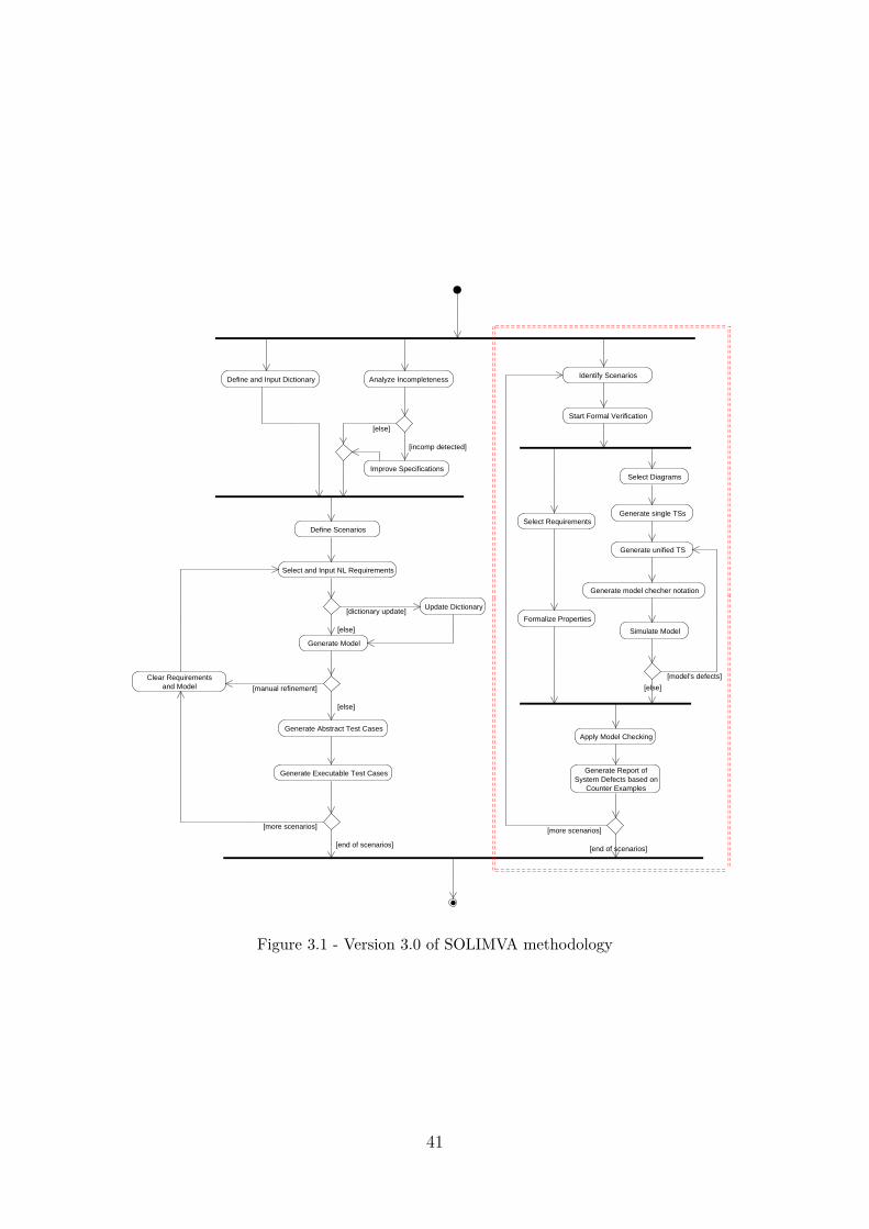
Define and Input Dictionary
Define Scenarios
Select and Input NL Requirements
Generate Model
Clear Requirementsand Model [manual refinement]
Generate Abstract Test Cases
Generate Executable Test Cases
[more scenarios]
[else]
Update Dictionary[dictionary update]
[else]
Analyze Incompleteness
Improve Specifications
[incomp detected]
[else]
[end of scenarios]
Identify Scenarios
Select Diagrams
Formalize Properties
Generate model checher notation
[more scenarios]
[end of scenarios]
Start Formal Verification
Select Requirements
Simulate Model
[model's defects]
Apply Model Checking
Generate Report of System Defects based on
Counter Examples
Generate single TSs
Generate unified TS
[else]
Figure 3.1 - Version 3.0 of SOLIMVA methodology
41

[more scenarios]
Identify Scenarios
Select Diagrams
Formalize PropertiesGenerate Model Checker Notation
[end of scenarios]
Start Formal Verification
Select Requirements
Simulate Model
[else]
[model's defects]
Apply Model Checking
Generate Report of System Defects based on
Counter Examples
Generate Unified TS
Generate single TSs
Figure 3.2 - Extending SOLIMVA: contribution of this PhD thesis
42

scenario’ (COCKBURN, 2000)) and each of the variations (’extensions andsub-variations’) are the scenarios identified by the present approach. Forexample, considering the classical ATM (Automated Teller Machine) sys-tem, there is a use case called Perform Transaction that states (BJORK,2012):
“The session is started when a customer inserts an ATM card into thecard reader slot of the machine. The ATM pulls the card into the machineand reads it. (If the reader cannot read the card due to improper insertionor a damaged stripe, the card is ejected, an error screen is displayed, andthe session is aborted.) The customer is asked to enter his/her PersonalIdentification Number (PIN), and is then allowed to perform a transaction,choosing from a menu of possible types of transaction. When the customerfinishes performing transactions, the card is ejected from the machine andthe session ends. The customer may abort the session by pressing theCancel key when entering a PIN or choosing a transaction type.”
In the present approach, one can consider the Perform Transaction UseCase as a scenario (containing the main success scenario and its variations).Observing its description, it is easy to identify its ’main success scenario’:it occurs when all goes well (the card is read, the PIN is correct, the userperform the transaction with success, the card is ejected). Sub-variationsmay also occur, as the PIN is incorrect, the card can not be read, and soon.
b) Start Formal Verification. Once the scenario is identified, it is time tobegin, in fact, the Formal Verification. This activity means that from thismoment on, everything will be prepared to start the Formal Verification.This can be observed in the next activities, which can be executed inparallel.
c) Select Requirements. Here, the requirements which need to be prop-erly executed by the system are selected. For each selected scenario, re-quirements are extracted from the textual description of use cases or fromNatural Language descriptions. The user should identify the suitable re-quirements which will be verified in the system model during the ModelChecking process. Considering the Perform Transaction Use Case, one pos-sible requirement to be chosen is: the customer can perform transactionsonly if he/she has a valid card and a valid personal identification number(PIN). Otherwise, he/she can not perform any kind of transaction. Cer-
43

tainly this is an important feature that the system should perform properly,and liable to be checked.
d) Formalize Properties. Once the requirements are selected, it is time toformalize the properties 1. The properties folllow the formalization pro-posed by means of specification patterns (DWYER et al., 1999) in LTL orCTL. To generate the properties from the available requirements, the firststep is to identify the atomic propositions within the requirements, onceLTL and CTL formula consists of atomic propositions, operators, and pathquantifiers (this last only for CTL).
Consider the description of a requirement in the Perform Transaction UseCase, presented in the previous item. It is possible to identify three atomicpropositions in this description: (i) a = “the customer can perform transac-tions”; (ii) b = “valid card”; (iii) c = “valid personal identification number”.After identifying the atomic propositions, the temporal sequence in whichthey occur must be analyzed, so one can verify in which scope and pat-tern (DWYER et al., 1999) the property fits. In this example, proposition ashould happen only after propositions b and c.
e) Select Diagrams. The activities related to model creation, which are Se-lect Diagrams, Generate single TSs, Generate Unified TS, Generate ModelChecker Notation, and Simulate Model, can be executed in parallel withthe Select Requirements and Formalize Properties activities. The first ac-tivity related to model creation, Select Diagrams, is when the respectivediagrams that represent the behavior related to the use case selected areidentified. Eventually, the use case selected does not have a representationin all the diagrams that this approach is intended to use. For example, ause case can be associated with a sequence and activity diagram but notwith a state machine diagram; or there are only the sequence and statemachine diagram for that use case but not the activity. In these cases, themodel must be generated from the available diagrams for that use case.But, it is considered that at least one sequence diagram is available forthe selected scenario. The choice for the sequence diagram occurred due toits acceptance. Most of the software specification that have been consultedpresented sequence diagrams modelling the systems. As the objective isthat the methodology is actually applied in practice, the choice for thesequence diagram provides greater possibility for this to happen.
1In the present work, requirement and property are considered synonyms
44

The next three activities which are shown in dashed line in Figure 3.2are automated by XMITS tool. These activities are detailed in the nextsubsection.
f) Generate Single TSs. Based on the available UML behavioral diagrams,a single TS (finite-state model) is generated and then a unified TS (Gener-ate Unified TS) is also generated. These activities along with GenerateModel Checker Notation are performed by XMITS tool. As explainedbefore, the present approach does not demand that all three UML behav-ioral diagrams (sequence, activity, behavioral state machines) exist: it isenough to have a sequence diagram to generate the TS.
g) Generate Model Checker Notation. The created TS is translated byXMITS into the input language of the NuSMV model checker (KESSLER,2015). Guidelines, which take into account the NuSMV syntax and thelanguage description discussed in Section 2.3.2.2, are detailed to accomplishthe translation. This is explained in Section 3.3.
h) Simulate Model. The model of the system is simulated prior to ModelChecking in order to get rid of modeling defects. Eliminating simple mod-eling defects before any form of thorough checking occurs may reduce thetime-consuming verification effort (BAIER; KATOEN, 2008). If more modeldefects are identified then the workflow returns to the Generate UnifiedTS activity and restart from this point. When there is no more remainingdefect in the model and all properties are created, Model Checking can beapplied.
i) Apply Model Checking. Finally, Model Checking is applied to identifydefects on the behavioral description of the system represented by the UMLdiagrams.
j) Generate Report of System Defects based on Counterexamples.Detected system defects are then reported. Having generated the reportfor one scenario, the user starts again selecting the next scenario. Thisprocess must be repeated until there is no more scenarios and the processis finalized.
In the next sections, details of the main activities of the present approach are pre-sented, i.e., a solution to generate a single TS based on UML behavioral diagrams.
45

The focus is on activitiesGenerate Single TSs,Generate Unified TS, andGen-erate Model Checker Notation, which are automated by XMITS tool. First, thesingle TS from each one of the diagrams is generated separately. Second, it is shownhow to obtain the definitive/unified TS from the combination of the individual TSs.Finally, the generation of the NuSMV notation is explained.
3.2 Transforming UML Behavioral Diagrams into Transition Systems(TS)
This section shows how to translate scenarios which are represented in UML behav-ioral diagrams (by sequence, state machine, and activity) into a single TransitionSystem, so that Formal Verification can be applied to the considered system. Oncethe properties to be checked and the scenario are identified, it is time to find outthe UML behavioral diagrams that model these scenarios.
First, this approach achieves individuals TSs from each one of the diagrams sepa-rately. Then, the definitive/unified TS is obtained from the combination of the threeindividual TSs.
3.2.1 Generation of Individual TSs
This section presents the translation of individual diagrams for simple examples.For brevity, sequence diagram is denoted as SD, behavioral state machine diagramas SMD, and activity diagram as AD. It is assumed that a scenario must have atleast one diagram describing it: the SD, which is mandatory, due to the explanationsgiven in the last section.
3.2.1.1 Translating Sequence Diagrams
The first diagram to analyze is the SD. In this approach, the SD is considered to bemandatory, that is, it is taken for granted that every use case has at least one SDdescribing it. As will be explained in Section 3.2.2, the SD gives the directives forthe combination of the diagrams, and because of this it is mandatory.
To extract the corresponding TS from an SD, it is necessary to look over the diagramstarting from the initial interaction. In general, an SD has a mainline sequence andoptionally several variations. The variations are usually represented using variouscombined fragments, like alternatives, option, parallel, and loop. Depending on thetype of the fragment, different variations can be easily identified. The variationswere identified from the approach presented in (SARMA; MALL, 2009), which were
46

adapted to the present work. The rules are described below:
a) Fragment option (opt): If the guard of the fragment opt is true, then allthe items specified within this fragment are executed. Thus, two variationsoccur, one with the additional interactions of the opt fragment and theother without it.
b) Fragment alternatives (alt): For an alt fragment, depending on the outcomeof the guard condition for each of the operand, different variations canoccur. Suppose the fragment alt has n number of operands, then n differentpossibilities would occur.
c) Fragment loop: For a loop fragment, for simplicity, we restrict that the loopbe executed at most one time. That is, either the loop is not executed at all(false condition of the loop), or the loop is executed once (truth conditionof the loop). Thus, it gives rise to at least two different possibilities.
d) Fragment parallel (par): Here there is a subtle difference fom the approachproposed in (SARMA; MALL, 2009). All regions are executed to occur inparallel. Identifying all possibilities in a par fragment is very difficult andit leads to a large number of alternatives.
Based on these rules, by extracting all possible execution paths of a given SD, onecan construct a corresponding TS. A state in the TS is composed by a messageand all the guards present in the SD, along with their values for that state. Bydefault, the TS initial state is set as null. Actually, the first state is the head ofthe list. The syntax of a state in the TS is identified by a tuple � (Message),g0, g1, ..., gn � where Message is each one of the messages present in the SD andg0,g1,...,gn represent all the existing guards in the SD along with their respectivevalues. In the initial state, the guard values are assigned as ’dc’, which means ’donot care’, because at the beginning the values can be either true or false. If there isparallelism, the parallel messages are combined with an ’and’. Table 3.1 shows theelements in UML and how they are represented in the TS. Last line represents twoparallel messages.
Combined fragments dictate the possible paths that an SD can reach. Transitionsare based on the sequencing of exchanged messages, that is, as the sequence diagramevolves, the TS also evolves. Algorithm 1 shows how to generate a single TS from agiven SD.
47

Table 3.1 - Translation from SD into TS
UML Transition System Initial ValueMessage = Register State = � (Register), ...� null
Guard = dataok State = � ..., dataok = dc, ...� dc
Message1 = Register State =Message2 = DisplayOptions � (RegisterandDisplayOptions), ...� -
As will be seen, the initialization is the same for the three diagrams: first, thealgorithm calls the Reader, which is the first module responsible for processing theSD. The SD is inputted as an XMI file. The operation of the modules is explained inChapter 4. The Reader identifies if it is a valid XMI file and which type of diagramit is (SD, AD, or SMD). Then, the function Collector.run, which is specific foreach diagram, is called to process it. The SD Collector gathers the main elements:Messages, Transitions, Combined Fragments, and Guards. These elements are thenclassified into six categories: State, Fork, Join, Decision, Connection, or Default.Table 3.2 shows how the elements of an SD are mapped into these generic categories.
Table 3.2 - Mapping elements of the SD into the generic categories
SD Element CategoryInitial State DefaultMessage State
Combined Fragments opt, loop, and alt DecisionCombined Fragment par Fork
Other elements Connection
All elements in a UML diagram are classified in this way, regardless of their originaldiagram. Then, the Converter Logic is called to processes the lists containing theelements, classified into these categories. Based on these elements, the Convertermodule calls the functions. It begins from the initial state and goes on untill allstates have been processed. The Converter Logic calls the Transition Function, which
48

performs a specific function, depending on the element:
Algorithm 1: Generate the TS from a given SDInput: SDOutput: single TS
1 reader.read(xml) // Call the Reader to process the XMI file2 diagramHandler.process(reader.getOutput()) // Identify if it is a valid XMI3 catch (Exception e) // If it is not a valid XMI, an exception is shown4 if reader.getOutput() is a valid XMI file then5 identifyDiagram() // Identify which diagram it is (SD, AD, or SMD)6 type = collectTypeDiagram();7 return type;8 SearchSpecificCollector(type) // Call the Collector, according to the type of
diagram (SD, AD, or SMD) to process the output of Reader9 Collector.run(reader.getOutput());
10 if type=SD then// The file is iterated by specific functions to collect the main SD
elements: Messages, Transitions, CombinedFragments, and Guards11 MessageCollectorFunction() // The text from the messages are saved in a
key/value data structure called Message Dictionary12 TransitionCollectorFunction() // The system uses the Message ID to generate
the transitions, which are stored in a Transition Dictionary13 ElementCollectorFunction() // The combined fragments are classified and
stored in the Element Dictionary14 GuardCollectorFunction() // All guards are stored in the Guards Dictionary
end// Then, a new processing is performed on these elements, starting with the
first state. All collected elements are classified and saved into lists,according to the following categories: State, Fork, Join, Decision,Connection, or Default
15 Collector.classify();// The Converter Logic is called to process the lists of the classified
elements16 Converter.logic();
// The Converter starts processing the Initial State. The Initial State callsthe Transition Function to processes its transitions
17 repeat18 Converter.TransitionFunction() // Call the Transition Function to process all
the transitions of this state19 builder.saveTransitionSystem(output) // Build the Transition System
until all the states are processed;// The Transition Function processes the next state. After processed, the
state calls the Transition Function again to process its transitions. Theprocess ends when all the states are processed
end
49

a) The Connection Function simply calls a Transition Function to process thetransitions.
b) The Decision Function splits the flow process according to the decisionnode’s guard value (true or false). It also saves the guard values in theoutput.
c) The Default Function does nothing. It is used, for instance, for the finalnode.
d) The Fork Function deals with parallel elements. It creates the parallel flow.
e) The Join Function deals with the synchronism of parallels flows after aFork. It is responsible to terminate a parallel processing correctly.
f) The State Function is responsible for processing the states of the diagramand to create the TS, which is the output of the Converter.
While the list is being processed, the functions call an instance of Builder, an im-portant class of the Global module, responsible for creating the Transition Systemoutput.
Returning to the example of the previous chapter, consider the SD shown in Figure2.2, for the Ordering use case. The resulting TS for it is presented in Figure 3.3.One can observe the two possible paths reached from opt fragment.
3.2.1.2 Translating Activity Diagrams
AD is not compulsory in the present approach to obtain the unified TS. AD focuseson representing activities which may or may not correspond to methods of classes,so they can model the behavior of a class as well of a system. An activity is a statewith an internal action and one or more outgoing transitions which automaticallyfollow the termination of the internal activity. If an activity has more than oneoutgoing transition, then these must be identified through conditions. AD’s typicallysupport description of sequencing, conditional dependency, parallel activities, andsynchronization aspects involved in different activities.
To build the corresponding TS, each activity and transitions are analyzed. To trans-late the transition behavior of the activities some specific nodes are identified:
a) Fork node: it separates a transition in several other transitions that areexecuted at the same time (parallel): there are n possible variations.
50
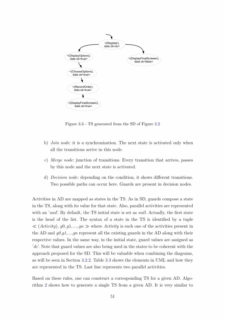
<(Register),data ok=dc>
<(DisplayOptions),data ok=true> <(DisplayFinalScreeen),
data ok=false>
<(ChooseOptions),data ok=true>
<(RecordOrder),data ok=true>
<(DisplayFinalScreeen),data ok=true>
Figure 3.3 - TS generated from the SD of Figure 2.2
b) Join node: it is a synchronization. The next state is activated only whenall the transitions arrive in this node.
c) Merge node: junction of transitions. Every transition that arrives, passesby this node and the next state is activated.
d) Decision node: depending on the condition, it shows different transitions.Two possible paths can occur here. Guards are present in decision nodes.
Activities in AD are mapped as states in the TS. As in SD, guards compose a statein the TS, along with its value for that state. Also, parallel activities are representedwith an ’and’. By default, the TS initial state is set as null. Actually, the first stateis the head of the list. The syntax of a state in the TS is identified by a tuple� (Activity), g0, g1, ..., gn� where Activity is each one of the activities present inthe AD and g0,g1,...,gn represent all the existing guards in the AD along with theirrespective values. In the same way, in the initial state, guard values are assigned as’dc’. Note that guard values are also being used in the states to be coherent with theapproach proposed for the SD. This will be valuable when combining the diagrams,as will be seen in Section 3.2.2. Table 3.3 shows the elements in UML and how theyare represented in the TS. Last line represents two parallel activities.
Based on these rules, one can construct a corresponding TS for a given AD. Algo-rithm 2 shows how to generate a single TS from a given AD. It is very similar to
51

Table 3.3 - Translation from AD into TS
UML Transition System Initial ValueActivity = Showproductslist State = � (Showproductslist), ...� null
Guard = dataok State = � ..., dataok = dc, ...� dc
Activity1 = Askcustomerdata State = � (AskcustomerdataActivity2 = Showproductslist andShowproductslist), ...� -
the algorithm presented to convert the SD. The main difference is the Collector,which classifies the elements that are specific to AD: nodes, edges, or guards. Then,the behavior is the same of Algorithm 1: the elements are classified into categories,saved in lists, and these lists are processed to generate the TS. Table 3.4 shows howthe elements of an AD are mapped into the generic categories.
Table 3.4 - Mapping elements of the AD into the generic categories
SD Element CategoryInitial Node DefaultActivity State
Decision Node DecisionFork Node ForkJoin Node JoinMerge Node Connection
Other elements Default
Figure 3.4 shows the corresponding TS for the activity diagram presented in Figure2.3 of previous chapter. This AD is modeling the same case study (Ordering) pre-viously presented for the SD. It is possible to observe that each branch in the AD
52

leads to different paths in the TS.
Algorithm 2: Generate the TS from a given ADInput: ADOutput: single TS
1 reader.read(xml) // Call the Reader to process the XMI file2 diagramHandler.process(reader.getOutput()) // Identify if it is a valid XMI3 catch (Exception e) // If it is not a valid XMI, an exception is shown4 if reader.getOutput() is a valid XMI file then5 identifyDiagram() // Identify which diagram it is (SD, AD, or SMD)6 type = collectTypeDiagram();7 return type;8 SearchSpecificCollector(type) // Call the Collector, according to the type of
diagram (SD, AD, or SMD) to process the output of Reader9 Collector.run(reader.getOutput());
10 if type=AD then// The file is iterated by specific functions to collect the main AD
elements: Nodes, Edges, or Guards11 NodeCollectorFunction() // All the elements classified as Node are stored in
the Element Dictionary12 EdgeCollectorFunction() // All the Edges are classified as Transition and
stored in the Transition Dictionary13 GuardCollectorFunction() // The function collects all guard conditions and
associates them with is specific decision structure. All the guards arestored in the Guards Dictionary
// Then, a new processing is performed on these elements, starting with thefirst state. All collected elements are classified and saved into lists,according to the following categories: State, Fork, Join, Decision,Connection, or Default
14 Collector.classify();// Now, the Converter Logic is called to process the lists of the classified
elements15 Converter.logic();
// The Converter starts processing the Initial State. The Initial State callsthe Transition Function to processes its transitions
16 repeat17 Converter.TransitionFunction() // Call the Transition Function to process all
the transitions of this state18 builder.saveTransitionSystem(output) // Build the Transition System
until all the states are processed;// The Transition Function processes the next state. After processed, the
state calls the Transition Function again to process its transitions. Theprocess ends when all the states are processed
53

<(Ask customer data),data ok=dc,order = dc>
<(Show products list),data ok=true,order = dc>
<(Display final screen),data ok=false,
order = dc>
<(Show message: “Ask order?”),data ok=true, order = dc>
<(Record ordering data),data ok=true,order = true>
<(Display final screen),data ok=true,order = true>
<(Display final screen),data ok=true,order = false>
Figure 3.4 - TS generated from the AD of Figure 2.3
3.2.1.3 Translating State Machine Diagrams
The SMD, as the AD, is not mandatory either. An SMD is composed of nodes andtransitions and each one of them is analyzed to build the corresponding TS. In thefollowing, it is explained how the nodes are analyzed.
a) Simple node: it is mapped as a simple state in the TS.
b) Composite node: consists of one or more regions. A region is a containerfor sub-states. A composite state can either be sequential or concurrent.In a sequential type of composite state, the state is considered to be anexclusive-or of its sub-states. That is, a composite state can be in any ofits sub-states, but not in more than one sub-state at any time. But, in aconcurrent type, the state is determined by a logical and of its sub-statesand the object is considered to be in all the concurrent states at the sametime.
c) Choice node: it is equivalent to if/else. So, here two situations can occur:one when the guard condition is set to true and the other when it is set tofalse. So, there are two paths to reach.
d) Join node: it represents a synchronization where the next state occurs onlywhen all the arrows arrive on the join node.
54

e) Fork node: the node may have one or more arrows from the node to states.Suppose there are n number of arrows, so n possibilities would occur.
f) Junction node: junction of transitions. Every transition that arrives, passesby this node and the next state is activated.
Based on these rules, one can construct a corresponding TS for a given SMD. Thereis a difference in the syntax when constructing the TS, related to SD and AD. Asin SMD one state can have several incoming events, a state in the SMD is mappedas states in the TS plus the event which triggered this state. Besides, guard valuesfor that state are mapped in the same way that they are mapped in SD and AD.States in SMD can be single or parallel (represented as ’and’).
The syntax of a state in the TS is identified by a tuple � (Event − State),g0, g1, ..., gn� where Event is each one of the events present in the SMD, State iseach one of the states present in the SMD, and g0,g1,...,gn represent all the exist-ing guards in the SMD along with their respective values. Also, in the initial state,guard values are assigned as ’dc’ and the TS initial state is set as null (list head).Table 3.5 shows the elements in UML and how they are represented in the TS. Notethat in the first line, the initial state has no event, so, a dash is put in place of whatwould be the name of the event. This is repeated every time there is no name forthe event which triggered the state. Line two shows the syntax with event.
Table 3.5 - Translation from SMD into TS
UML Transition System Initial ValueInitial State = Idle State = � (−− Idle), ...� null
Event = DataEntry State = � (DataEntry−State = V alidatingData V alidatingData), ...� -
Guard = dataok State = � ..., dataok = dc, ...� dc
State1 = Idle State = � (−IdleandState2 = V alidatingData −V alidatingData), ...� -
Algorithm 3 shows how to build a TS from an SMD. It has the same behavior ofthe last two algorithms presented. The difference is also in the Collector. Here, theSMD is divided as: Elements (which can be State, Pseudo State, or Final State)and Transitions. Table 3.6 shows how the elements of an SMD are mapped into thegeneric categories.
aaaaaaaa
55

aaaaaaaa
Algorithm 3: Generate the TS from a given SMDInput: SMDOutput: single TS
1 reader.read(xml) // Call the Reader to process the XMI file2 diagramHandler.process(reader.getOutput()) // Identify if it is a valid XMI3 catch (Exception e) // If it is not a valid XMI, an exception is shown4 if reader.getOutput() is a valid XMI file then5 identifyDiagram() // Identify which diagram it is (SD, AD, or SMD)6 type = collectTypeDiagram();7 return type;8 SearchSpecificCollector(type) // Call the Collector, according to the type of
diagram (SD, AD, or SMD) to process the output of Reader9 Collector.run(reader.getOutput());
10 if type=SMD then// The file is iterated by specific functions to collect the main SMD
elements: Elements and Transitions11 ElementCollectorFunction() // All elements classified as State, Pseudo State
or Final State12 TransitionCollectorFunction() // All transitions are stored in the Transition
Dictionary
// Then, a new processing is performed on these elements, starting with thefirst state. All collected elements are classified and saved into lists,according to the following categories: State, Fork, Join, Decision,Connection, or Default
13 Collector.classify();// Now, the Converter Logic is called to process the lists of the classified
elements14 Converter.logic();
// The Converter starts processing the Initial State. The Initial State callsthe Transition Function to processes its transitions
15 repeat16 Converter.TransitionFunction() // Call the Transition Function to process all
the transitions of this state17 builder.saveTransitionSystem(output) // Build the Transition System
until all the states are processed;// The Transition Function processes the next state. After processed, the
state calls the Transition Function again to process its transitions. Theprocess ends when all the states are processed
Figure 3.5 shows the corresponding TS for the state machine diagram presented inFigure 2.4. Also, the SMD is modeling the same case study (Ordering). It is possibleto observe the different paths extracted from the events.
56

Table 3.6 - Mapping elements of the SMD into the generic categories
SD Element CategoryState State
Choice Node DecisionFork Node ForkJoin Node Join
Junction Node ConnectionTerminate Node DefaultOther elements Default
<(- -Idle)>
<(Data Entry-Validating data)>
<(- -Displaying Options)>
<(- -Registering Order)>
<(Invalid Data-Idle)>
<(Back-Idle)>
Figure 3.5 - TS generated from the SMD of Figure 2.4
Now it is presented how a unified TS can be achieved from each one of the individualTSs obtained from the UML diagrams.
3.2.2 The Unified Transition System
In this subsection, it is shown how to generate the final/unified TS. Some defini-tions and notations used in this approach are given in the sequence. As previouslymentioned, it is assumed that a scenario must have at least one diagram describingit: the SD. In the following the syntax of the unified TS is detailed.
A state in the unified TS is identified by a tuple � (Message, Activity, Event −State), g0, g1, ..., gn � where Message is from SD; Activity from AD; and Event-State is from SMD; g0,g1,...,gn represent all the existing guards in all the diagrams
57
along with their respective values. At the beginning, all guard values are assigned to’dc’ for the same reasons presented before, for creating the individual TSs. If thereare parallel messages, states, or activities, an ’and’ is inserted in the tuple, such as�(Msg1andMsg2, Activity1andActivity2, Event1State1andEvent2State2), ... �,which means that Msg1 and Msg2 are sent in parallel, as well as Activity1 andActivity2, and State1 and State2 are parallel states.
There are situations that should be considered. They were divided into two cases:
a) The first one is when a diagram is missing, that is, the scenariothat is being analyzed is not represented in all the three diagrams.It is possible that the AD is missing; or the SMD is missing; orboth, the AD and SMD are missing. The part representing the di-agram that is missing in the corresponding TS is substituted byan underscore ’_’. In these situations, states are described as �(Message, Activity,−), g0, g1, ..., gn � or � (Message,−, Event −State), g0, g1, ..., gn�, or � (Message,−,−), g0, g1, ..., gn�.
b) The second one happens because the diagrams do not model thesame behavior all the time. Some situations can be more detailed inan SMD than in an SD diagram, or does not even appear in theSD diagram. When this happens, diagrams are incoherent or incon-sistent. In these situations, states in the unified TS are described as� (Message, Activity,−), g0, g1, ..., gn � or � (Message,−, Event −State), g0, g1, ..., gn�, or� (−, Activity, Event−State), g0, g1, ..., gn�,and all its variations. Note that in this case, it is possible that the SD doesnot contain a behavior which can be more detailed in the AD. So, the case� (−, Activity, Event − State), g0, g1, ..., gn � may happen. That doesnot mean that the SD is missing. Simply, that particular behavior is notmodeled on the SD.
The main challenge to combine the three diagrams is to define the correspondenceamong messages, events, and activities. For instance, an event for a transition of theSMD can be a message of the SD, while the message can be a call to an activitymodeled by an AD. Nevertheless, finding where a specific message of the SD ismodeled in the SMD or in the AD is very hard. Instead, the final TS is built usingthe individual TSs. The algorithm looks over the TSs starting from their initialstates. The correspondence among states of each TS is assigned by using the flow of
58

transitions. At each iteration, the algorithm parses the three TSs and construct thenew states by taking the next possible transitions in each TS.
The flow of transitions, alone, is not enough to construct the final TS, as eachTS contains multiple paths. In addition, guard values are used to help finding thecorrespondence among states. As already stated, the SD is mandatory and conductsthe diagrams merging. The basic elements that delineate the possibility of pathsin the SDs are guards on the combined fragments. Thus, guard values are adoptedalong with the flow of transitions to construct the final TS states. If one thinks ofan algorithm, at each iteration, the algorithm seeks the next possible transitions ineach TS and their guard values.
To find out states that have the same guard values, the gvs (guard value structure)was created. The gvs represents the values of each one of all available guards oneach state. Every time, for each possible next transitions of the TSs created fromthe SD, SMD, and AD, their gvs are verified and a match of their values is created.Thereafter, new states are generated.
<(A),g=dc>
<(B),g=dc>
<(C),g=dc>
<(D),g=false>
<(E),g=true>
<(1),g=dc>
<(2),g=false>
<(3),g=true>
<(A-1),g=dc>
<(B-1),g=dc>
<(C-1),g=dc>
<(D-2),g=false>
<(E-3),g=true>
Diagram 1 Diagram 2 1 and 2 together
<(1),g=dc>
<(2),g=false>
<(3),g=true>
<(A),g=dc>
<(B),g=false>
<(C),g=true>
<(A-1),g=dc>
<(B-2),g=false>
<(C-3),g=true>
gvs in next(A)={(g=false),(g=true)}
<(A),g1=dc,g2=dc>
<(B),g1=false,g2=dc>
<(D),g1=false,g2=false>
<(C),g1=true,g2=dc>
<(1),g1=dc,g2=dc>
<(2),g1=false,g2=dc>
<(4),g1=false,g2=true>
<(3),g1=true,g2=dc>
<(A-1),g1=dc,g2=dc>
<(B-2),g1=false,g2=dc>
<(--4),g1=false,g2=true>
<(C-3),g1=true,g2=dc>
<(D--),g1=false,g2=false>
a)
b)
gvs in next(A)={(g=dc)}
gvs in next(A)={(g1=false,g2=dc),(g1=true,g2=dc),(g1=false,g2=false)}
gvs in next(1)={(g=false),(g=true)}
gvs in next(1)={(g=false),(g=true)}
gvs in next(1)={(g1=false,g2=dc),(g1=true,g2=dc),(g1=false,g2=true)}
c)
gvs in next(A-1)={(g=false),(g=true)}
gvs in next(C-1)={(g=false),(g=true)}
gvs in next(A-1)={(g1=false,g2=dc),(g1=true,g2=dc),(g1=false,g2=true),(g1=false,g2=false)}
Figure 3.6 - Possible situations to generate the unified TS and its respective gvs
59

Figure 3.6 shows the three possible situations that may occur to generate a state inthe final TS. All other cases found end up falling in one of these three cases. Rowsare representing the three cases a, b, and c. The TS in column 3 is the combinationof the TSs in columns 1 and 2.
Situation a) is straightforward to see. All the gvs match and the combination isexplicit. Situation b) shows how the algorithm handles cases when in at least one ofthe next possible states, the value of its gvs is the same of the current gvs value. Thisoccurs because the diagrams do not model the same behavior during their evolution.In this case, the TSs have different lengths. Here, only the TS which has the valueof its next gvs equal to the current evolves. The other TS keeps standing until thenext gvs match, or the TS processing complete. Situation c) shows an example ofinconsistent states, due to inconsistent diagrams. As previously discussed, this mayhappen when one of the diagrams models a behavior that is not modeled in theother diagram and vice versa. New transitions are created, as many as necessary tocover all possibilities of gvs values.
The three situations presented in Figure 3.6 represent the rules to unify the diagramsbased on the gvs. These rules were implemented in XMITS as an array list. Theywere defined as “Rules Dictionary”. The Rules Dictionary is an array containingfour rules: First Rule, Second Rule, and Third Rule, which represent, respectively,situations a, b, and c of Figure 3.6; and Fourth Rule, which is applied when thereare no next states, that is, when the diagram was all consumed. In this case, thediagram is taken out from the processing. When building the unified TS, these rulesare always called in the order in which they are held in the array. Figure 3.7 showsthe structure of the Rules Dictionary.
1
2
3
First Rule
Second Rule
Third Rule
Rules DictionaryArrayList
4
Fourth Rule
Figure 3.7 - Details of the Rules Dictionary
60

To perform this approach, before combining the TSs, three situations must be con-sidered:
a) TSs with no guards. All the TSs that are being combined have no guards.For example, a sequence diagram with no combined fragments, or onlywith parallel combined fragment. All other combined fragments requireguards. Or an activity diagram with no decision node. Or a behavioralstate machine diagram with different incoming events. In the absence ofguards, it is quite easy to construct the final TS: all that is required is tofollow the flow of transitions. At each iteration, all the next possible statesare combined. Note that it is possible to have multiple paths, and that allthe combinations must be done, as can be seen in Figure 3.8.
<(A and B)>
<(C)>
<(B)><(A and C)>
<(a)>
<(y-c)>
SD SMD
<(x-b)>
<(A and B, a)>
<(C, x-b)><(B, x-b)>
<(A and C, x-b)>
<(A and C, y-c)><(B, y-c)>
<(C, y-c)>
The two TSs combined
Figure 3.8 - Combining TSs with no guards
b) One TS has guards and the other one does not. At the beginning,the algorithm seeks all guards in all diagrams. Suppose TS1 has guards g1and g2 and TS2 has no guards. The gvs will be composed by {g1, g2} and itis assigned to TS2. As originally TS2 did not contain {g1,g2}, their valuesare assigned as “dc” and will never change. Thenceforth the situationsare covered in Figure 3.6. Figure 3.9 shows how the approach handle thissituation.
c) TSs with different guards. It is similar to the previous case. At the
61

<(A),g1=dc,g2=dc>
<(C),g1=false,g2=dc>
<(B),g1=true,g2=dc>
<(y-c),g1=dc,g2=dc>
SD -> {g1,g2} SMD ->{ }
<(x-b),g1=dc,g2=dc>
<(A,a),g1=dc,g2=dc>
<(A,x-b),g1=dc,g2=dc>
<(B,_),g1=true,g2=dc>
<(C,_),g1=false,g2=dc>
<(A,y-c),g1=dc,g2=dc>
The two TSs combined
<(a),g1=dc,g2=dc>
<(B,_),g1=true,g2=dc>
<(C,_),g1=false,g2=dc>
Figure 3.9 - Combining TSs when one TS has guards and the other one does not
beginning, the algorithm seeks all guards in all diagrams. Suppose TS1has guards g1 and g2 and TS2 has guard g3. The gvs will be composedby {g1, g2, g3} and it is assigned to TS1 and TS2. As originally TS2 didnot contain g1,g2, their values are assigned as “dc” and will never change,as well as TS1 will receive g3, which is assigned as “dc” and will neverchange. Thenceforth the situations are covered in Figure 3.6. Figure 3.10shows how the approach handles this situation.
Algorithm 4 shows how to build the unified TS, applying all the guidelines that havebeen explained so far. The single TSs are the input, which must contain at least oneelement generated from an SD diagram. The TSs are saved in the TSDictionary(line 2). At each iteration, the Repeat loop tries apply one of the four rules to thediagrams (lines 5 to 16), until all states of all diagrams have been analized:
a) The First Rule looks for equal next states in all diagrams. If, and only if,all the states from all diagrams are equal at the same time, it is possibleto create a unified state. If all the next states are equal, the first rule williterate all diagrams and create a unified state with those states, saving itin the Builder class (lines 15-16).
b) The Second Rule verifies all next states. If at least one diagram does notchange its gvs in the next state, only this diagram is iterated and then the
62
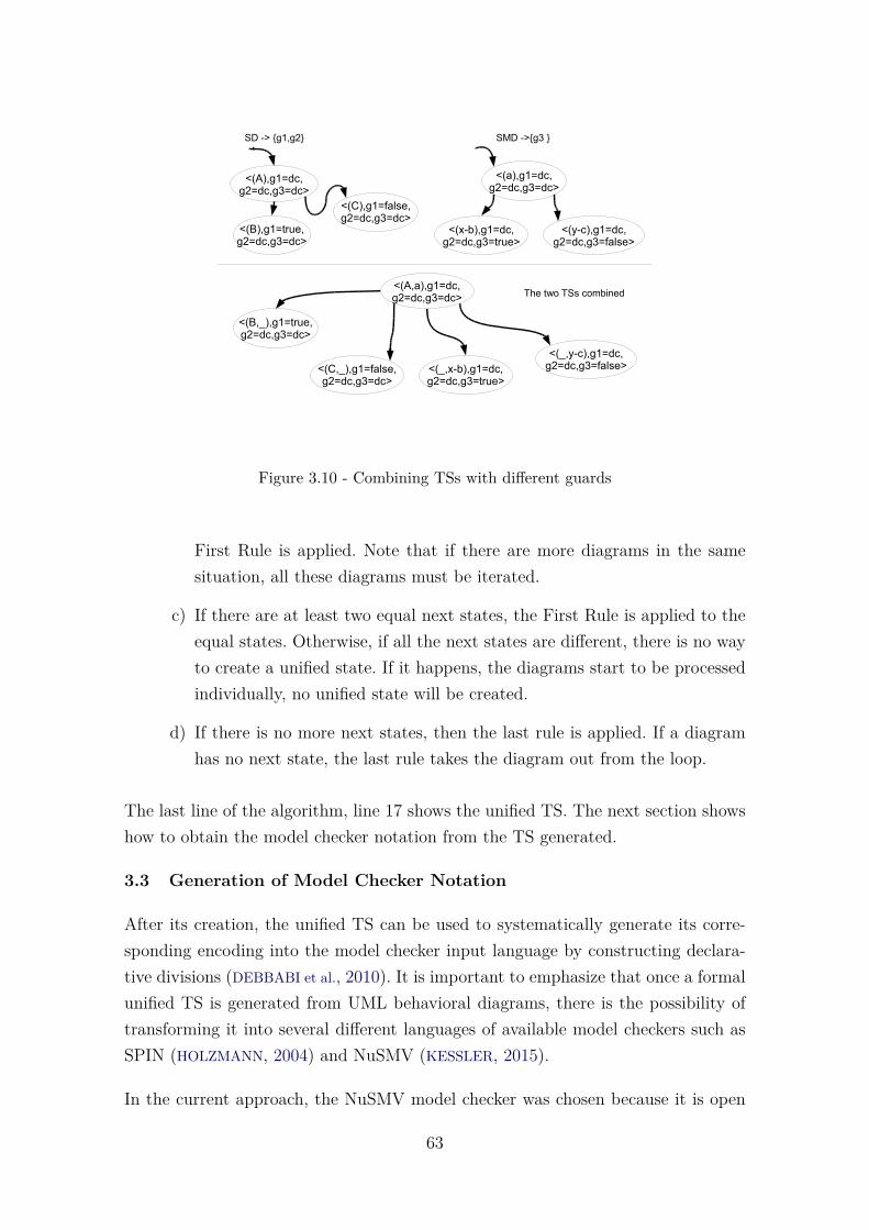
<(A),g1=dc,g2=dc,g3=dc>
<(C),g1=false,g2=dc,g3=dc>
<(B),g1=true,g2=dc,g3=dc>
<(y-c),g1=dc,g2=dc,g3=false>
SD -> {g1,g2} SMD ->{g3 }
<(x-b),g1=dc,g2=dc,g3=true>
<(A,a),g1=dc,g2=dc,g3=dc>
<(B,_),g1=true,g2=dc,g3=dc>
<(C,_),g1=false,g2=dc,g3=dc>
The two TSs combined
<(a),g1=dc,g2=dc,g3=dc>
<(_,x-b),g1=dc,g2=dc,g3=true>
<(_,y-c),g1=dc,g2=dc,g3=false>
Figure 3.10 - Combining TSs with different guards
First Rule is applied. Note that if there are more diagrams in the samesituation, all these diagrams must be iterated.
c) If there are at least two equal next states, the First Rule is applied to theequal states. Otherwise, if all the next states are different, there is no wayto create a unified state. If it happens, the diagrams start to be processedindividually, no unified state will be created.
d) If there is no more next states, then the last rule is applied. If a diagramhas no next state, the last rule takes the diagram out from the loop.
The last line of the algorithm, line 17 shows the unified TS. The next section showshow to obtain the model checker notation from the TS generated.
3.3 Generation of Model Checker Notation
After its creation, the unified TS can be used to systematically generate its corre-sponding encoding into the model checker input language by constructing declara-tive divisions (DEBBABI et al., 2010). It is important to emphasize that once a formalunified TS is generated from UML behavioral diagrams, there is the possibility oftransforming it into several different languages of available model checkers such asSPIN (HOLZMANN, 2004) and NuSMV (KESSLER, 2015).
In the current approach, the NuSMV model checker was chosen because it is open
63
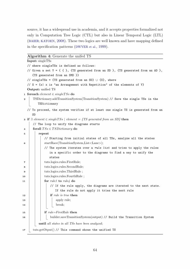
source, it has a widespread use in academia, and it accepts properties formalized notonly in Computation Tree Logic (CTL) but also in Linear Temporal Logic (LTL)(BAIER; KATOEN, 2008). These two logics are well known and have mapping definedin the specification patterns (DWYER et al., 1999).
Algorithm 4: Generate the unifed TSInput: singleTSs// where singleTSs is defined as follows:// Given a set Y = { { }, {TS generated from an SD }, {TS generated from an AD },
{TS generated from an SMD }}// singleTSs = {TS generated from an SD} ∪ {X}, where// X = {x| x is "an Arrangement with Repetition" of the elements of Y}Output: unified TS
1 foreach element ∈ singleTSs do2 TSDictionary.addTransitionSystem(TransitionSystem) // Save the single TSs in the
TSDictionary
// To proceed, the system verifies if at least one single TS is generated from anSD
3 if ∃ element ∈ singleTSs | element = {TS generated from an SD} then// The loop to unify the diagrams starts
4 forall TSs ∈ TSDictionary do5 repeat
// Starting from initial states of all TSs, analyze all the states6 startRace(TransitionSystem,List<Lane>);
// The system iterates over a rule list and tries to apply the rulesin a specific order to the diagrams to find a way to unify thestates
7 tuts.logics.rules.FirstRule;8 tuts.logics.rules.SecondRule;9 tuts.logics.rules.ThirdRule ;
10 tuts.logics.rules.FourthRule ;11 for rule1 to rule4 do
// If the rule apply, the diagrams are iterated to the next state.If the rule do not apply it tries the next rule
12 if rule is true then13 apply rule;14 break;
15 if rule=FirstRule then16 builder.saveTransitionSystem(output) // Build the Transition System
until all states in all TSs have been analyzed;
17 tuts.getOtput() // This command shows the unified TS
64

Considering the NuSMV model checker, declaration of variables is relatively easy, aspresented in Subsection 2.3.2.2. One variable called State is related to the element�(Message,Activity,Event-State)� of the tuple that identifies a certain state of theTS. In addition, there will be as many variables as the guards identified within theUML behavioral diagrams, i.e. g0 is transformed into a variable vg0 of enumerativetype, g1 into a variable vg1, and so on. All these variables derived from the guardswill be enumerated with the following values: {dc, false, true}. The dc value is im-portant because in many occasions and especially at the beginning of the behavioralsystem modeling, the values of certain guards either do not care or do not makesense be true or false. Another remark is that the use of only state variables ofNuSMV.
Table 3.7 shows the elements in the TS and how they are represented in the NuSMV.States are grouped into enumerations, as well as the guards. Each transition isrepresented by the CASE construct.
Table 3.7 - Translation from the unified TS into NuSMV
Unified TS NuSMV Initial ValueState Variable State of
Enumerative typeGuard Variable of dc
Enumerative typeTransition CASE construct
The initial value of the State variable of the final TS in NuSMV is always initializedwith the initial state to mark the starting point of the diagram. Note that this is notthe “full” state characterization of the initial state of the NuSMV model becausewe depend on the values of the variables representing the guards to know this. Togenerate the model in NuSMV we simply follow the transitions of the unified TS,making appropriate assignments to the State variable and for each variable derivedfrom the guards. To illustrate the proposed translation, consider the TS of Figure3.3. Applying the proposed guidelines, one can obtain the code presented in Figure3.11.
To automate this activity (Generate Model Checker Notation), a grammar wasdeveloped. At first, the process to translate a TS into NuSMV imposes no restriction.Name of messages in sequence diagrams, activities in activity diagrams, and eventsand states in state machine diagrams were not adequate to become values of variables
65

Defining a subset of NuSMV input language using Backus–Naur Form.
<nusmv-code> ::= “MODULE main” <EOL><variable-declaration> “ASSIGN” <EOL><statements>[“CTLSPEC” <formalized-ctl-logic> | “LTLSPEC” <formalized-ltl-logic>]
<variable-declaration> ::= <variable-declaration> | “VAR” <EOL><identifier> “:” <EOL><enumeration-type> “ ;” | <boolean-type> “ ;”
<identifier> ::= <ident-first-charact> | <identifier ident-consecutive-charact>
<enumeration-type> ::= “{“ <integer-numbers> ”}” | “{“ <symbolic-constants> ”}” | “{“ <integer-numbers><symbolic-constants> ”}”
<boolean-type> ::= “TRUE” | “FALSE”
<ident-first-charact> ::= “A” | “B” | “C” | “D” | “E” | “F” | “G” | “H” | “I” | “J” | “K” | “L” | “M” | “N” | “O” | “P” | “Q” | “R” | “S” | “T” | “U” | “V” | “W” | “X” | “Y” | “Z” | “a” | “b” | “c” | “d” | “e” | “f” | “g” | “h” | “i” | “j” | “k” | “l” | “m” | “n” | “o” | “o”| “q”| “r”| “s” | “t” | “u” | “v” | “w” | “x” | “y” | “z”| “_”
<ident-consecutive-charact> ::= <ident-first-charact> | <digit> | “$” | “#” | “-”
<digit> ::= “0” | “1” | “2” | “3” | “4” | “5” | “6” | “7” | “8” | “9”
<integer-numbers> ::= <digit> | “-”<digit>
<symbolic-constants> ::= “A” | “B” | “C” | “D” | “E” | “F” | “G” | “H” | “I” | “J” | “K” | “L” | “M” | “N” | “O” | “P” | “Q” | “R” | “S” | “T” | “U” | “V” | “W” | “X” | “Y” | “Z” | “a” | “b” | “c” | “d” | “e” | “f” | “g” | “h” | “i” | “j” | “k” | “l” | “m” | “n” | “o” | “o”| “q”| “r”| “s” | “t” | “u” | “v” | “w” | “x” | “y” | “z”|
<statements> ::= <statements> | <initial-state> <transition-relation>
<initial-state> ::= <initial-state> | “ “ | “init” “(“ <identifier> ”) := ” <enumeration-type> “ ;” | <boolean-type> “ ;”
<transition-relation> ::= <transition-relation> | “ “ | “next” “(“ <identifier> ”) := ” <EOL>“case” <EOL><transicao> <EOL>“TRUE: “ <identifier> “ ;” <EOL>“esac ;”
MODULE main
VAR
State:
{Register, DisplayOptions, ChooseOptions, RecordOrder, DisplayFinalScreen};
data ok:
{dc,false,true};
ASSIGN
init(State):= Register;
init(data ok):= dc;
next(State):=
case
State=Register & data ok=true : DisplayOptions;
State=Register & data ok=false : DisplayFinalScreen;
State=DisplayOptions & data ok=true : ChooseOptions;
State=ChooseOptions & data ok=true : RecordOrder;
State=RecordOrder & data ok=true : DisplayFinalScreen;
TRUE: State;
esac;
VAR
State:
{Register, DisplayOptions, ChooseOptions, RecordOrder, DisplayFinalScreen};
MODULE main
VAR
MODULE main
VAR
VAR
State:
{Register, DisplayOptions, ChooseOptions, RecordOrder, DisplayFinalScreen};
data ok:
{dc,false,true};{dc,false,true};
ASSIGN
init(State):= Register;
init(data ok):= dc;
next(State):=
case
init(State):= Register;
init(data ok):= dc;
next(State):=
case
State=Register & data ok=true : DisplayOptions;
State=Register & data ok=false : DisplayFinalScreen;
State=DisplayOptions & data ok=true : ChooseOptions;
State=ChooseOptions & data ok=true : RecordOrder;
State=RecordOrder & data ok=true : DisplayFinalScreen;
State=Register & data ok=true : DisplayOptions;
State=Register & data ok=false : DisplayFinalScreen;
State=DisplayOptions & data ok=true : ChooseOptions;
State=ChooseOptions & data ok=true : RecordOrder;
State=RecordOrder & data ok=true : DisplayFinalScreen;
TRUE: State;
esac;
Figure 3.11 - NuSMV code for the TS of Figure 3.3
in NuSMV. Thus, a context-free grammar was defined in order to structure the codein NuSMV, as can be seen in Figure 3.12. The grammar was written using the BNF(Backus-Naur Form) (NAUR et al., 1963), one of the main notation techniques forcontext-free grammars.
The grammar defines all the syntax to build the smv file: the variable declaration,identifiers, and so on, exactly as defined in the NuSMV manual (CAVADA et al.,2005). The grammar defines the main parts of the NuSMV file: the header, variabledeclaration, and statements. The header is the same for every NuSMV code. Thereare a number of restrictions related to variable declaration: the variable identifieris composed by first character and consecutive character. Each one has specificallowed types of digits, leters, numbers, and symbols. Statements are composed ofstatements, initial state, and transition relation. The grammar defines each one ofthem. There is also the properties to be verified, which start with CTLSPEC orLTLSPEC. XMITS uses this grammar to generate the NuSMV notation.
The next section presents a running example to illustrate all activities proposed inSOLIMVA 3.0.
66

Defining a subset of NuSMV input language using Backus–Naur Form.
<nusmv-code> ::= “MODULE main” <EOL><variable-declaration> “ASSIGN” <EOL><statements>[“CTLSPEC” <formalized-ctl-logic> | “LTLSPEC” <formalized-ltl-logic>]
<variable-declaration> ::= <variable-declaration> | “VAR” <EOL><identifier> “:” <EOL><enumeration-type> “ ;” | <boolean-type> “ ;”
<identifier> ::= <ident-first-charact> | <identifier ident-consecutive-charact>
<enumeration-type> ::= “{“ <integer-numbers> ”}” | “{“ <symbolic-constants> ”}” | “{“ <integer-numbers><symbolic-constants> ”}”
<boolean-type> ::= “TRUE” | “FALSE”
<ident-first-charact> ::= “A” | “B” | “C” | “D” | “E” | “F” | “G” | “H” | “I” | “J” | “K” | “L” | “M” | “N” | “O” | “P” | “Q” | “R” | “S” | “T” | “U” | “V” | “W” | “X” | “Y” | “Z” | “a” | “b” | “c” | “d” | “e” | “f” | “g” | “h” | “i” | “j” | “k” | “l” | “m” | “n” | “o” | “o”| “q”| “r”| “s” | “t” | “u” | “v” | “w” | “x” | “y” | “z”| “_”
<ident-consecutive-charact> ::= <ident-first-charact> | <digit> | “$” | “#” | “-”
<digit> ::= “0” | “1” | “2” | “3” | “4” | “5” | “6” | “7” | “8” | “9”
<integer-numbers> ::= <digit> | “-”<digit>
<symbolic-constants> ::= “A” | “B” | “C” | “D” | “E” | “F” | “G” | “H” | “I” | “J” | “K” | “L” | “M” | “N” | “O” | “P” | “Q” | “R” | “S” | “T” | “U” | “V” | “W” | “X” | “Y” | “Z” | “a” | “b” | “c” | “d” | “e” | “f” | “g” | “h” | “i” | “j” | “k” | “l” | “m” | “n” | “o” | “o”| “q”| “r”| “s” | “t” | “u” | “v” | “w” | “x” | “y” | “z”|
<statements> ::= <statements> | <initial-state> <transition-relation>
<initial-state> ::= <initial-state> | “ “ | “init” “(“ <identifier> ”) := ” <enumeration-type> “ ;” | <boolean-type> “ ;”
<transition-relation> ::= <transition-relation> | “ “ | “next” “(“ <identifier> ”) := ” <EOL>“case” <EOL><transicao> <EOL>“TRUE: “ <identifier> “ ;” <EOL>“esac ;”
Figure 3.12 - Context-Free Grammar to convert the output of the Converter or of theTUTS into the NuSMV Model Checker Notation.
67

3.4 A Running Example
This section presents a running example to illustrate the activities proposed in theSOLIMVA methodology version 3.0. Consider more thoroughly the ATM classicalexample, where the ATM interacts with a customer via a specific interface andcommunicates with the bank over an appropriate communication link. A user thatrequests a service from the ATM has to insert a card and enter a personal identifica-tion number (PIN). Both pieces of information (card number and PIN) need to bevalidated. If the credentials of the customer are not valid, the card is ejected. Other-wise, the customer carries out operations that he/she chooses, such as deposit, cashwithdrawal, printing receipts, and so on. When the custumer finishes the operationthe card is returned to him/her. Figure 3.13 shows the system use case diagram.
Customer
Withdraw CashDepositPrint Receipt
Validate User
Bank«include»
Perform Transaction
Figure 3.13 - ATM Use Case diagram
In accordance with SOLIMVA 3.0, the first activity is Identify Scenarios, observ-ing the use cases. Let’s consider the use case Perform Transaction (described inSection 3.1) as a scenario to be verified, containing the main success scenario andits variations. Once the scenario is identified, it is time to begin, in fact, the For-mal Verification (Start Formal Verification). For this, two things are needed: theproperty to be verified and a model of the system.
To generate a model of the system, five activities must be performed. The firsttwo activities to perform are Select Diagrams and Generate Single TSs. Forsimplicity, to facilitate the understanding of the translation, it is presented onlythe first part of the diagrams, which represents validation of customer credentials.
68

<(InsertCard),Cardok=dc,Pinok=dc,Balok=dc>
<(VerifCard()),Cardok=dc,Pinok=dc,Balok=dc>
<(CardStatus),Cardok=dc,Pinok=dc,Balok=dc>
<(WaitPIN),Cardok=dc,Pinok=dc,Balok=dc>
<(PIN),Cardok=dc,Pinok=dc,Balok=dc>
<(ejectCard),Cardok=false,Pinok=dc,Balok=dc>
<(verifPIN()),Cardok=true,Pinok=dc,Balok=dc>
<(PINStatus),Cardok=true,Pinok=dc,Balok=dc>
... ...
Figure 3.14 - Part of ATM Sequence Diagram and its respective TS
Figure 3.14 presents the initial part of ATM sequence diagram and its respectiveindividual TS. Figures 3.15 and 3.16 show the UML behavioral state machine, andactivity diagrams modeling the initial part of ATM description, respectively, aswell as the individual TSs obtained from each one of the diagrams. The sequencediagram has an alt combined fragment, which leads to two paths. The TS obtainedfrom the SMD has multiple paths, due to parallel states. The activity diagram hasalso parallel activities, which leads to multiple paths.
Continuing, the next activity related to model generation isGenerate Unified TS.Applying the suggested approach on the three diagrams, the TS shown in Figure3.17 is achieved. Actually, Figure 3.17 exhibits part of the unified TS, only the partsthat are shown in Figures 3.14, 3.15, and 3.16. Note that to generate the unifiedTS, all rules based on the gvs (guard value structure) presented in Figure 3.6 wereapplied.
Other two activities remaining to model generation areGenerate Model CheckerNotation, and Simulate Model. Each state is characterized by the values of the
69

<(IDLE),Cardok=dc,Pinok=dc,Balok=dc>
<(VERIFCARD and VERIFYPIN),Cardok=dc, Pinok=dc,
Balok=dc>
<(CARDVALID and VERIFYPIN),Cardok=true,
Pinok=dc,Balok=dc>
<(EJECT),Cardok=false,Pinok=dc,Balok=dc>
...
<(VERIFCARD and PININVALID),Cardok=dc, Pinok=false,
Balok=dc>
<(VERIFCARD and PINVALID),Cardok=dc, Pinok=true,
Balok=dc>
<(CARDVALID and PININVALID),Cardok=true, Pinok=false,
Balok=dc>
<(CARDVALID and PINVALID),Cardok=true, Pinok=true,
Balok=dc>
<(EJECT),Cardok=false,Pinok=false,Balok=dc>
<(EJECT),Cardok=true,Pinok=false,Balok=dc>
<(CARDVALID and PININVALID),Cardok=true, Pinok=false,
Balok=dc>
<(EJECT),Cardok=false,Pinok=true,Balok=dc>
...
Figure 3.15 - Part of ATM Behavioral State Machine Diagram and its respective TS
variables. There were identified four main variables that characterize the TS:
a) State={(InsertCard,Idle,InsertCard),...,(PinStatus,VerifyPin,Autho-rizePin)};
b) CardOk = {dc,false,true}. CardOk represents the card validation;
c) PinOk = {dc,false,true}. PinOk represents the PIN validation; and
d) BalOk = {dc,false,true}. BalOk represents the available amount of thecustomer account. CardOk, PinOK and BalOk comes from the guardsidentified within the UML diagrams.
Using the guidelines and the grammar proposed in last section, it is possible toobtain the NuSMV code for the TS. Figure 3.18 shows the code partially.
Activity Simulate Model is performed to validate the model. Before applyingModel Checking, it is necessary to simulate the model to see if it is consistent.
70

<(InsertCard),Cardok=dc,Pinok=dc,Balok=dc>
<(ReadCard and EnterPIN),Cardok=dc,Pinok=dc,
Balok=dc>
<(ReadCard),Cardok=dc,Pinok=dc,Balok=dc>
<(AuthorizeCard),Cardok=dc,Pinok=dc,Balok=dc>
<(AuthorizePIN),Cardok=true,Pinok=dc,Balok=dc>
<(EjectCard),Cardok=false,Pinok=dc,Balok=dc>
...
...
<(EnterPIN),Cardok=dc,Pinok=dc,
Balok=dc>
Figure 3.16 - Part of ATM Activity Diagram and its respective TS
When running the model checker, this activity is very valuable, because one cansee all possible states and all reachable states. Indeed, when running NuSMV modelchecker for this ATM example, in total, there are 756 states, 86 of which are reachablestates. Figure 3.19 shows the three UML diagrams, now complete, used to performthe case study. From left to right, one can see the sequence, state machine, andactivity diagrams.
With respect to the property, two activities must be performed: Select Require-ments and Formalize Properties. Considering the use case Perform Transaction,it is possible to extract two relevant user-defined properties related to requirements.As the TS has multiple paths, Computation Tree Logic (CTL) (BAIER; KATOEN,2008) was chosen to formalize the properties. Note that the properties could beformalized using LTL as well, considering that NuSMV supports both.
a) Requirement 1: the customer can perform transactions only if he/she hasa valid card and a valid personal identification number (PIN). Otherwise,he/ she can not perform any kind of transaction. This property can be
71
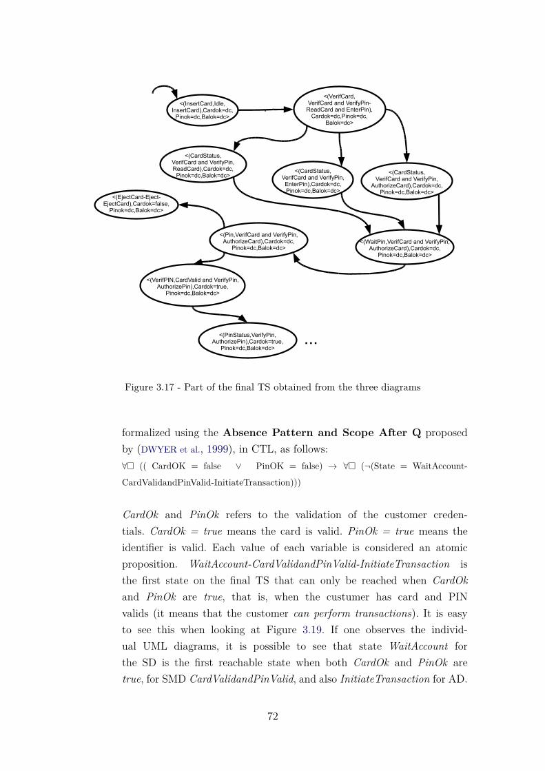
<(VerifCard,VerifCard and VerifyPin-
ReadCard and EnterPin),Cardok=dc,Pinok=dc,
Balok=dc>
<(InsertCard,Idle,InsertCard),Cardok=dc,
Pinok=dc,Balok=dc>
<(EjectCard-Eject-EjectCard),Cardok=false,
Pinok=dc,Balok=dc>
<(WaitPin,VerifCard and VerifyPin,AuthorizeCard),Cardok=dc,
Pinok=dc,Balok=dc>
<(CardStatus,VerifCard and VerifyPin,
AuthorizeCard),Cardok=dc,Pinok=dc,Balok=dc>
...
<(CardStatus,VerifCard and VerifyPin,ReadCard),Cardok=dc,
Pinok=dc,Balok=dc><(CardStatus,
VerifCard and VerifyPin,EnterPin),Cardok=dc,Pinok=dc,Balok=dc>
<(Pin,VerifCard and VerifyPin,AuthorizeCard),Cardok=dc,
Pinok=dc,Balok=dc>
<(VerifPIN,CardValid and VerifyPin,AuthorizePin),Cardok=true,
Pinok=dc,Balok=dc>
<(PinStatus,VerifyPin,AuthorizePin),Cardok=true,
Pinok=dc,Balok=dc>
Figure 3.17 - Part of the final TS obtained from the three diagrams
formalized using the Absence Pattern and Scope After Q proposedby (DWYER et al., 1999), in CTL, as follows:∀� (( CardOK = false ∨ PinOK = false) → ∀� (¬(State = WaitAccount-
CardValidandPinValid-InitiateTransaction)))
CardOk and PinOk refers to the validation of the customer creden-tials. CardOk = true means the card is valid. PinOk = true means theidentifier is valid. Each value of each variable is considered an atomicproposition. WaitAccount-CardValidandPinValid-InitiateTransaction isthe first state on the final TS that can only be reached when CardOkand PinOk are true, that is, when the custumer has card and PINvalids (it means that the customer can perform transactions). It is easyto see this when looking at Figure 3.19. If one observes the individ-ual UML diagrams, it is possible to see that state WaitAccount forthe SD is the first reachable state when both CardOk and PinOk aretrue, for SMD CardValidandPinValid, and also InitiateTransaction for AD.
72

Figure 3.18 - Part of the NuSMV code for the TS of Figure 3.17
b) Requirement 2: whenever the specified amount exceeds the level of availablefunds, it should be possible for the user to request a new cash advanceoperation if the user wishes to correct the amount. The property can beformalized using the Existence Pattern and Scope After Q proposedby (DWYER et al., 1999), in CTL, as follows:¬∃ [ ¬ (State = InsuffFunds-Modify-ShowBalance ∧ ∀♦ (State = CashAdvance-Chkbal-
CheckBalance)) ∪ (State = InsuffFunds-Modify-ShowBalance ∧ ¬ (State = InsuffFunds-
Modify-ShowBalance ∧ ∀♦ (State = CashAdvance-Chkbal-CheckBalance)))]
Here, the state that allows the customer to perform a cash operationis CashAdvance-Chkbal-CheckBalance and the state that indicates thatthe available funds are insufficient is InsuffFunds-Modify-ShowBalance.To formalize the properties, it is necessary to see the final TS and itsvariables.
73
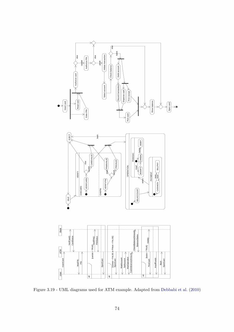
Ent
er P
IN
Rea
d ca
rdA
utho
rize
card
Initi
ate
tran
sact
ion
Inse
rt c
ard
Aut
horiz
e P
IN
card
ok
els
e
pino
k
Sel
ect a
ccou
nt
Che
ck b
alan
ce
els
e balo
kD
ebit
acco
unt
Rec
ord
tran
sact
ion
Dis
pens
e ca
sh
Prin
t rec
eipt
Pic
k ca
sh
Sho
w b
alan
ce
Eje
ct c
ard
els
e
IDLE
VE
RIF
Y
CH
KC
AR
D
CH
KP
IN
EJE
CT
VE
RIF
CA
RD
CA
RD
VA
LID
card
ok
e
lse
VE
RIF
YP
IN
PIN
VA
LID
PIN
INV
ALI
Del
se
pino
k
OP
ER
AT
ION
SE
LAC
CO
UN
T
TR
AN
SA
C
PA
YM
EN
T
CA
SH
AD
VB
ILLP
AY
next
next
MO
DIF
YC
HK
BA
LD
EB
ITse
lect
back
balo
k
insu
f
:AT
M:U
ser
:Ban
kIn
sert
Car
d
Ver
ifCar
d()
Car
dSta
tus
Wai
tPIN
PIN
alt
[car
dok
= T
RU
E]
Ver
ifPIN
()
PIN
Sta
tus
Eje
ctC
ard
alt
[car
dok
= F
ALS
E o
r P
INok
= F
ALS
E]
E
ject
Car
d
Wai
tAcc
ount
Wai
tOpe
ratio
n
Sel
Acc
ount
Cas
hAdv
ance
(Am
ount
)
Che
ckB
alan
ce(A
mou
nt)
Bal
ance
Sta
tus
alt
[bal
ok =
TR
UE
]
Deb
it()
Pic
kCas
h
Insu
ffFun
ds
Bac
k
Eje
ctC
ard
Figure 3.19 - UML diagrams used for ATM example. Adapted from Debbabi et al. (2010)
74

Next activity of SOLIMVA 3.0 is Apply Model Checking. After applying ModelChecking, the results indicate that the first property is satisfied. However, the secondproperty is violated, as can be seen in the counterexample shown in Figure 3.20. Eachline represents one state in the TS. When analyzing the counterexample, one cannote that it is not possible to reach state CashAdvance-ChkBal-CheckBalance fromstate InsuffFunds-Modify-ShowBalance.
Figure 3.20 - Counterexample for property 2
Activity Generate Report of System Defects based on CounterExamplesis implemented by the XMITS, when it generates the final txt file, as can be seenin the next chapter.
3.5 Final Remarks
This chapter presented the proposed solution to allow applying Model Checking tosoftware developed in accordance with UML. It presented SOLIMVA 3.0 and theactivities that make up the methodology. The details of the translation of UMLdiagrams to individual Transition Systems were explained, as well as the algorithmsto allow these translations.
After that, the translation to a unified Transition System was detailed. It was ex-plained how a new state is composed, the rules that conducts the unification, andthe algorithm that implements the junction. Then, the guidelines and a grammarto transform the unified TS to the input language of NuSMV model checker weredescribed. And finally, a running example was presented to illustrate the methodol-ogy.
The next chapter presents XMITS, the tool that was developed for automate the
75

main activities of SOLIMVA 3.0. The XMITS modules and its architecture areexplained.
76

4 XMITS - XML Metadata Interchange to Transition System
This chapter presents XMITS - XML Metadata Interchange to Transition System,a tool developed to support the main three activities proposed in SOLIMVA 3.0(shown in Figure 4.1), to achieve Model Checking of UML-based software:Generatesingle TSs, Generate Unified TS, and Generate Model Checker Notation.An abridged version of this chapter can be seen in (SANTOS et al., 2014b), whichpresented a very preliminary version of XMITS, and in (ERAS et al., 2015), wherethe actual version of XMITS is presented.
Generate single TSs
Generate Unified TS
Generate Model Checker Notation
Figure 4.1 - Activities of SOLIMVA 3.0 automated by XMITS
XMITS is essential to the application of SOLIMVA 3.0. The development of XMITSis part of an effort to allow the use of Formal Methods in practice, to real softwareprojects. The tool facilitates the process of applying Formal Verification during thesoftware development, so that it becomes transparent to the user. Briefly explaining,the analyst considers a use case, with its narrative description, or requirements inNatural Language; and also the corresponding UML behavioral diagrams that repre-sent the solution to meet the requirements (use cases or pure textual requirements)are taken into account.
XMITS performs a three-step translation. First, it translates individual types ofdiagrams (SD, AD, SMD) into a TS in a simple intermediate format. After that,XMITS merges all single TSs into a unified TS. Finally, the tool transforms this
77

unified TS into the notation of the model checker (NuSMV). Requirements are for-malized using a temporal logic, such as CTL or LTL, following Dwyer’s specificationpatterns (DWYER et al., 1999). If there is a problem with the design (UML behavioraldiagrams), a counterexample is presented by the model checker.
Due to the modular nature proposed for the system, a language that supports theobject-oriented programming paradigm was chosen: Java (ORACLE, 2011). The aimwas to develop a tool that is extensible. If one wants to add another UML diagramto the approach, this can be easily implemented in XMITS. Eclipse (The Eclipse Foun-dation, 2015) was the Integrated Development Environment (IDE) chosen for imple-menting XMITS. UML 2.4.1 specifications were considered to produce the designartifacts. The design artifacts are then exported into XMI (XML Metadata Inter-change) format, and are inputted to XMITS. XMI is a standard of OMG (ObjectManagement Group) (OMG, 2015) for exchanging metadata information via Exten-sible Markup Language (XML). The most common use of XMI is as an interchangeformat for UML models, although it can also be used for serialization of modelsof other languages (metamodels). OMG has a documentation of formally releasedversions of XMI.
Figure 4.2 - Flow diagram of XMITS
78

Figure 4.2 presents a data flow within XMITS. The tool interoperates with two othertools: Modelio 3.2 (MODELIOSOFT, 2011), that is the software used to produce theUML artifacts; and the NuSMV model checker. XMITS consists of five modules, ofwhich four of them can be viewed in Figure 4.2: the Reader, that transforms theXMI file to a list of tags; the Converter, that transforms the list of tags to a singleTS; the TUTS (The Unified Transition System), that transforms the single TSsto the unified TS; and the Bridge module, that transforms the unified TS to themodel checker notation. There is still the Global module, that is not shown in thefigure, which controls several functions. All these modules are detailed in the nextsection.
4.1 XMITS Architecture
The actual XMITS software architecture is shown in Figure 4.3, where it is possibleto visualize all the five modules of the tool. In total, there are 121 classes: 7 for theReader Module; 61 for the Converter Module; 26 for the TUTS Module; 7 for theBridge Module; and 20 for the Global Module. There are about 11,120 lines of codeinstructions.
All XMITS modules work together following a sequence of interactions to producethe final output. Figure 4.4 shows the detailed workflow related to XMITS. Theprocess begins by the XMI files produced in the Modelio software. XMITS canprocess n XMI files. This is because sometimes there are two activity diagramsrelated to the scenario being analyzed; or three sequence diagrams. In this way, dueto each combination of the three accepted UML behavioral diagrams, it is possibleto process n XMI files. The only restriction is that, as previously emphasized, itdemands that at least one SD must be available. For n XMI files, XMITS calls ninstances of the Reader and n instances of the Converter. All the Converter outputsfeed the TUTS, which, in turn, combines the Transition Systems into a unique TS.
Once this is done, it is possible to call the Bridge module to translate the TransitionSystem into the NuSMV notation. The Global module has also a Printer functionto visualize the Transition System output directly in the Java terminal, or save itas a txt file. Follows are the details of XMITS modules.
4.1.1 The Reader Module
To process any XMI input, the first action is to convert the file to a useful format.The Reader module is responsible for converting the XMI into a structure for the
79

TUTS
-converter: Converter-builder: Buider-exception: Exception
+addDiagram(XMI)+run( )+getTransitionSystem(): List()
Exceptions
Reader
-nodeList: List()-exception: Exception
+parse(XMI)+getNodeList(): List()
Bridge
-output: String
+getOutput(TransitionSystem): String
Builder
-transitionSystem: List()
+saveState()+getTransitionSystem(): List()
Converter
-reader: Reader-builder: Buider-exception: Exception
+run( )+getTransitionSystem(): List()
Bridge
Global
TUTSConverterReader
«access»«access»
«access»
«access»«access»
«access» «access»
Figure 4.3 - XMITS software architecture
Figure 4.4 - XMITS detailed workflow
80
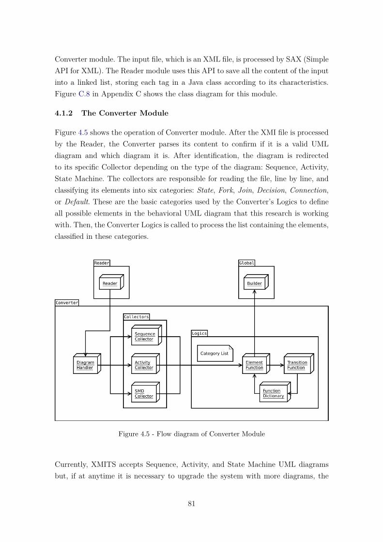
Converter module. The input file, which is an XML file, is processed by SAX (SimpleAPI for XML). The Reader module uses this API to save all the content of the inputinto a linked list, storing each tag in a Java class according to its characteristics.Figure C.8 in Appendix C shows the class diagram for this module.
4.1.2 The Converter Module
Figure 4.5 shows the operation of Converter module. After the XMI file is processedby the Reader, the Converter parses its content to confirm if it is a valid UMLdiagram and which diagram it is. After identification, the diagram is redirectedto its specific Collector depending on the type of the diagram: Sequence, Activity,State Machine. The collectors are responsible for reading the file, line by line, andclassifying its elements into six categories: State, Fork, Join, Decision, Connection,or Default. These are the basic categories used by the Converter’s Logics to defineall possible elements in the behavioral UML diagram that this research is workingwith. Then, the Converter Logics is called to process the list containing the elements,classified in these categories.
Figure 4.5 - Flow diagram of Converter Module
Currently, XMITS accepts Sequence, Activity, and State Machine UML diagramsbut, if at anytime it is necessary to upgrade the system with more diagrams, the
81
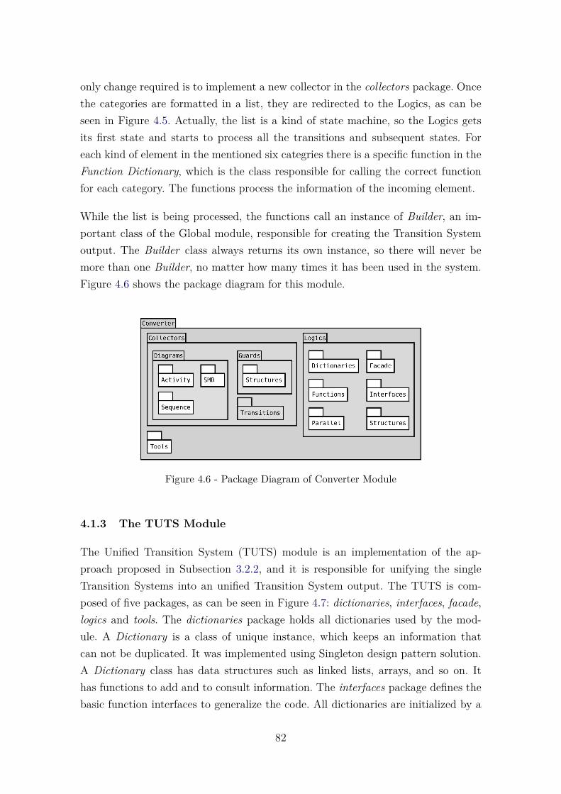
only change required is to implement a new collector in the collectors package. Oncethe categories are formatted in a list, they are redirected to the Logics, as can beseen in Figure 4.5. Actually, the list is a kind of state machine, so the Logics getsits first state and starts to process all the transitions and subsequent states. Foreach kind of element in the mentioned six categries there is a specific function in theFunction Dictionary, which is the class responsible for calling the correct functionfor each category. The functions process the information of the incoming element.
While the list is being processed, the functions call an instance of Builder, an im-portant class of the Global module, responsible for creating the Transition Systemoutput. The Builder class always returns its own instance, so there will never bemore than one Builder, no matter how many times it has been used in the system.Figure 4.6 shows the package diagram for this module.
Figure 4.6 - Package Diagram of Converter Module
4.1.3 The TUTS Module
The Unified Transition System (TUTS) module is an implementation of the ap-proach proposed in Subsection 3.2.2, and it is responsible for unifying the singleTransition Systems into an unified Transition System output. The TUTS is com-posed of five packages, as can be seen in Figure 4.7: dictionaries, interfaces, facade,logics and tools. The dictionaries package holds all dictionaries used by the mod-ule. A Dictionary is a class of unique instance, which keeps an information thatcan not be duplicated. It was implemented using Singleton design pattern solution.A Dictionary class has data structures such as linked lists, arrays, and so on. Ithas functions to add and to consult information. The interfaces package defines thebasic function interfaces to generalize the code. All dictionaries are initialized by a
82

facade class stored in the facade package. The core processing happens inside thelogics package. Finally, the tools package provides many important functions for theunification process.
Figure 4.7 - Package Diagram of TUTS Module
The flow of processing inside the TUTS is based on an iteration on the TransitionSystem inputs, unifying each state of each Transition System according to a rule.Algorithm 4, presented in Section 3.2.2, shows how the unified TS is generated.Each Transition System represents a UML diagram transformed by the ConverterModule. They are processed all together, side by side, like cars running on a racetrack. To walk from a state to another, the iterator needs to obey rules in a specificorder (actually, these rules are based on the gvs - guard value structure - explainedin Figure 3.6). All these rules are stored in a Rule Dictionary, in the dictionariespackage. The Rule Dictionary is an array list containing the four rules, as can beseen in Figure 3.7. If the states fit in the First Rule, there is a specific kind ofiteration; if not, the system tries to apply the Second Rule, and so on. The last ruleis an “end of race”, a function that simply stops all the iterators because there isnothing more to iterate, i.e., all the diagrams reach their last state. This processcan be observed in Figure 4.8.
The gvs can be formalized as follows. Given that a Transition System is composed ofstates and that each state w contains its own gvs, the gvsw is defined as an orderedn-tuple (x1, x2, ..., xn), where n is a positive integer and x1, x2, ..., xn is a distinctsequence of elements. An element xk of the tuple represents a guard along with itsvalue. Two ordered n-tuples (x1, x2, ..., xn) and (y1, y2, ..., yn) are equal if, and onlyif, xi = yi, ∀ i = 1...n.
83

Figure 4.8 - The iteration over the diagrams in the TUTS module
Let p be a state of a Transition System. Nextgvs(p) is defined as the set of all gvsof the next states of p. It is written as Nextgvs(p) = {gvs1, gvs2, ..., gvsk}, whereelements gvs1, gvs2, ..., gvsk represent the gvs of each one of the k next states of p.A state q is a next state of p if, and only if, there exists a transition from state p tostate q, written as p→ q.
Returning to Algorithm 4, let S = {s1, s2, ..., sm} be the set of states of the currentiteration, each one representing a digram, as can be seen in Figure 4.8. The fourrules are defined as follows:
a) First Rule: ∀ a ∈ Nextgvs(s1) ∃ b ∈ Nextgvs(sj) | a = b, j = 2...m.
b) Second Rule: ∃ sk ∈ S | gvssk= r, where r ∈ Nextgvs(sk).
c) Third Rule: if ∃ a ∈ Nextgvs(s1), then a 6= b ∀ b ∈ Nextgvs(sj) ,j = 2...m.
d) Fourth Rule: All the other cases.
The First Rule expects to find all states in the iterators position with the sameguard conditions. This rule means “all states are equal”, and it is the only time inthe process when the Builder class is called to generate an output. An unified stateis possible if, and only if, all the states are equal. If all states are not equal then
84

the system tries the Second Rule. The Second Rule looks for a scenario where somediagrams changed their guard conditions but others did not. In this hybrid conditionthe iterator advances just the diagrams which did not change, and the First Rulecan be applied. If the Second Rule wasn’t applied, then the system tries the ThirdRule. Here not all states are equal. If there are at least two equal states, the FirstRule is applied to them. Then, if all diagrams have different states, there is no wayto create a unified state, so all diagrams start to run in a different thread with nointeraction with the others. If even the Third Rule wasn’t applied, there is a FinalRule to end all the process.
Every time the diagrams can not be unified, the system divides the process and anew thread is created. This process happens when a division occurs in the diagramor in the Third Rule, when all states are different. In this way, TUTS avoids joiningdifferent states and simplifies the process. While there is more than one threadrunning, the Builder class falls into a concurrency of processes, trying to save aTransition System. To solve this, the save function runs into a critical region.
4.1.4 The Bridge Module
The Bridge module is responsible for translating the TSs into the notation of theNuSMV model checker. It allows to translate both the output of the Converter aswell as the output of TUTS. So, if one needs to translate only a single TS, it ispossible. Thus, the Bridge module allows the translation of both the single TSs orthe unified TS.
The Bridge module accomplishes the model transformation using the context-freegrammar shown in Figure 3.12. As already explained in Section 3.3, the grammardefines all the syntax of NuSMV. It is possible to visualize the output directlyin Java terminal or save it in a file. To make the conversion, the Bridge moduleiterates all over the Transition System several times, one for creating each sectionof the output file: header, variables, initial state (Assign), transitions (Next), andguards. There is a function dedicated to create each one of these sections of theNuSMV file. Then, the formater() function iterates over all String values lookingfor non accepted characters and replaces then in order to apply the rules defined bythe grammar. Figure C.9 in Appendix C shows the class diagram for this module.
85
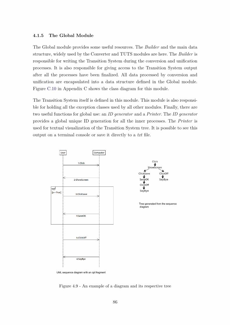
4.1.5 The Global Module
The Global module provides some useful resources. The Builder and the main datastructure, widely used by the Converter and TUTS modules are here. The Builder isresponsible for writing the Transition System during the conversion and unificationprocesses. It is also responsible for giving access to the Transition System outputafter all the processes have been finalized. All data processed by conversion andunification are encapsulated into a data structure defined in the Global module.Figure C.10 in Appendix C shows the class diagram for this module.
The Transition System itself is defined in this module. This module is also responsi-ble for holding all the exception classes used by all other modules. Finally, there aretwo useful functions for global use: an ID generator and a Printer. The ID generatorprovides a global unique ID generation for all the inner processes. The Printer isused for textual visualization of the Transition System tree. It is possible to see thisoutput on a terminal console or save it directly to a txt file.
Figure 4.9 - An example of a diagram and its respective tree
86

The printed version by the tool is a breadth-first search in this Transition Systemtree. It presents the name of each state, the guard conditions and, in the sequencediagram, who sent and who received each message. Figure 4.9 shows an exampleto illustrate a diagram and its tree and Figure 4.10 shows the output file for thisdiagram. Note that the first line of the output file shows the number of childrennodes that each node has. Note also that the first state is null; the first state isthe head of the list. The first state of any diagram is always null, because all thedata structure used in the output of the application is a list with a head. As thediagram used is a sequence diagram, there is a description of who sent and receivedthe message. In the end, the total number of states identified by the Converter ispresented.
When there is a condition, the tree displays different paths. When the condition istrue, the stream goes to the left, when it is false, it follows to the right, as shown inFigure 4.9. In this example, there is a branch because of the opt fragment. In thisway, all the possibilities for implementation of the diagrams presented in Section 3.2are predicted.
4.2 Final Remarks
This chapter has presented XMITS, the tool developed to support three activitesproposed in SOLIMVA 3.0 methodology: Generate single TSs, Generate Uni-fied TS, and Generate Model Checker Notation. XMITS is essential to theapplication of SOLIMVA 3.0, which aims to allow the use of Formal Methods inpractice, to real software projects.
All the modules of XMITS were explained, as well as the operation of each one ofthem. XMITS is composed of five main modules: the Reader, the Converter, theTUTS, the Bridge, and the Global module. The tool aims to be modular and readyfor upgrade. All its architecture was think to be generic and flexible. One of the mostimportant characteristics of the architecture used in XMITS tool is the aperture toimplement new modules and add new features in the existent modules.
Appendix C presents step-by-step, how to use the tool. It also shows the classdiagrams of Reader, Bridge, and Global modules. The next chapter shows SOLIMVA3.0 applied to two case studies in the aerospace area.
87

Figure 4.10 - Output file for the diagram shown in Figure 4.9
88

5 APPLICATION OF SOLIMVA 3.0 TO SPACE SOFTWARE
The goal of this chapter is to present the aplication of SOLIMVA 3.0 and its sup-porting tool, XMITS, to two real space software products. In total, the methodologywas applied to twenty scenarios considering the two case studies.
This chapter is organized as follows. The next section details the first case study:Software for the Payload Data Handling Computer (SWPDC). It shows the projectdescription, its architecture, main objectives, as well as the scenarios explored. Theresults for each scenario are presented. Section 5.2 shows the same explanation, butrelated to the Software for the Payload Data Handling Computer - protoMIRAXExperiment (SWPDCpM).
5.1 SWPDC - Software for the Payload Data Handling Computer
This case study is a space application software product, SWPDC, developed in thecontext of the Qualidade do Software Embarcado em Aplicações Espaciais (QSEE- Quality of Space Application Embedded Software) research product (SANTIAGO
et al., 2007). QSEE was an experience in outsourcing the development of softwareembedded in satellite payload. INPE was the customer and there were two SWPDC’ssuppliers: INPE itself and a Brazilian software company.
Figure 5.1 shows the physical architecture defined for QSEE project. Note the fol-lowing computing units in the architecture: On-Board Data Handling (OBDH) Com-puter, Payload Data Handling Computer (PDC), Event Pre-Processors (EPPs; EPPH1 and EPP H2), and Ionospheric Plasma Experiments (IONEX) Computer. OBDHis the satellite platform computer in charge of processing platform and payload in-formation and formatting/generating data to be transmitted to Ground Stations.The Payload is composed of two scientific instruments (note the dashed rectangles).However, for the purpose of this case study, the main instrument is the one in whichPDC exists, because SWPDC is embedded into PDC. The main goal of PDC isto obtain scientific data from EPPs and to transmit them to the OBDH. EPPsare front-end processors in charge of fast data processing of X-ray camera signals(SANTIAGO JÚNIOR, 2011).
The main functions of SWPDC software product are (SANTIAGO et al., 2007):
a) Interaction with EPPs in order to collect Scientific, Diagnosis, and TestData;
89

OBDH(Simulation Software)
PDC(SWPDC)
EPP H1(Data
Simulation)
EPP H2(Data
Simulation)
TemperatureSimulation
IONEX
TemperatureSimulation
Converter
USB DAQ
RS-232
ADC
RS-232
InstrumentsRS-232
Figure 5.1 - Physical architecture defined for QSEE project. Caption: ADC = Analog-to-Digital Converter; DAQ = Data Acquisition Board; RS-232 = RecommendedStandard 232; USB = Universal Serial Bus. SANTIAGO JÚNIOR (2011)
b) Data Formatting;
c) Memory management to store data temporarily before transmission to theOBDH;
d) Implementation of flow control mechanisms;
e) Housekeeping Data generation;
f) Implementation of complex fault tolerance mechanisms; and
g) Loading of new programs of the fly.
This case study has, therefore, almost all the functions of data handler computersfor space applications and thus, the characteristics of SWPDC are representative ofan important class of software in space domain.
In order to apply SOLIMVA 3.0 methodology, two documents were consulted: theSoftware Requirements Specification of QSEE (SRS), one of the artifacts generatedduring SWPDC’s development lifecycle; and INPE-16677-RPQ/850 Research Report(JÚNIOR et al., 2010), developed in a partnership between INPE and CIFASIS (CentroInternacional Franco Argentino de Ciencias de la Información y de Sistemas), whose
90

goal was to accomplish a comparison between Statecharts and Z language (SPIVEY;
ABRIAL, 1992), and to propose a complementing approach.
The SRS describes the technical specification of SWPDC, showing the environments,requirements, functional modeling, behavioral modeling, restrictions, and limitationsof the software. Behavioral modeling is represented by means of two UML diagrams:sequence diagram and activity diagram. The modeling procedure is given by rep-resentation of scenarios. Such scenarios were used as the scenarios of the casestudies (remembering the first activity of SOLIMVA 3.0: Identify Scenarios). TheINPE-16677-RPQ/850 Research Report shows the scenarios proposed by an expertand modeled in Statecharts. Therefore, the two documents together are valuable in-puts to apply SOLIMVA 3.0 methodology, since most of the scenarios are specifiedusing sequence diagram, activity diagram, and Statecharts.
As some of the features of Harel’s Statecharts are not covered in UML 2.0, the Stat-echarts models of the Research Report were rewritten as UML state machines. Onesuch example is shown in Figure 5.2. On the left, Scenario 1 is represented usingUML state machine. On the right, the same Scenario 1 is represented using State-charts. Observe that the changes were performed because of the events tr[In(IniM_-POST)] and endtime[In(SafeM_Etered)]. ’In(IniM_POST)’ predicate returns trueif the state machine is in the state IniM_POST. This predicate allows coordina-tion among parallel regions. As this predicate is not implemented in XMITS, thestates from where these transitions start were modeled as parallel with the statesIniM_POST and SafeM_Etered. Actually, that is what happens in practice.
5.1.1 Scenarios of SWPDC
In the case study, eight scenarios of SWPDC were chosen to be carried out. Asalready mentioned, these scenarios were obtained from SWPDC’s SRS, from theINPE-16677-RPQ/850 Research Report, and from (SANTIAGO JÚNIOR, 2011).
a) Scenario 1: PDC initiation process;
b) Scenario 2: Switching EPP Hxs on and off;
c) Scenario 3: Changing software parameters in the Safety Operation Mode;
d) Scenario 7: Housekeeping Data Transmission in the Nominal OperationMode;
91

PDCOff
IniM_POST
SafeM_Entered
SafeM_VerOp
SafeM_EPPsOff
Idle
CountingTime
[switchPDCOn/start60s]
[POSTOk]
[VER_OP_MODE/INFO_OP_MODE]
[tsinc]
[switchPDCOff]
[endtime]
UML State Machine Model: Scenario 1
Statechart Model: Scenario 1
Statechart Model: Scenario 1
Figure 5.2 - Scenario 1 represented in Statecharts and adapted to UML State Machine
e) Scenario 8: Housekeeping Data Transmission in the Nominal OperationMode, Robustness (reception), Load new programs;
f) Scenario 9: Dump Data of Program Memory in the Nominal OperationMode;
g) Scenario 10: Dump Data of Program Memory in the Nominal OperationMode, Robustness (command and reception); and
h) Scenario 12: Dump Data of Data Memory (Page 0) in the Nominal Oper-ation Mode, Robustness (command and reception).
In the next subsections scenarios 1, 3, and 8 are detailed. Not all the scenariosare detailed to make text not exhausting. Subsection 5.1.2 summarizes the resultsobtained from all the scenarios analyzed.
92

5.1.1.1 Scenario 1: PDC Initiation Process
In this scenario, the main actor is the PCD (Power Conditioning Unit) that switchesthe PDC computer on. The flow involves: to accomplish hardware verification, toobtain current PDC temperature, to generate startup report, to configure PDC statewith standard values, and to divert the control to the main module when in safetyoperation mode.
There are three UML diagrams which represent Scenario 1: a sequence, an activity,and a state machine diagram, illustrated in Figures 5.3, 5.4, 5.5, respectively. Fouruser-defined properties for this scenario, related to requirements, were verified.
PCD : SWPDC : EPP :
1: powerOn()
2:iniciar()
3:verificarHardware()
4: obterStatusAlimentacao(HX1,HX2)
5:gerarRelatoPOST()
6:reconfigurar()
7:mudarModoOperacao()
8:ativarModuloPrincipal()
Figure 5.3 - Sequence Diagram for Scenario 1
a) Property 1: The POST (Power-On Self Test) shall comprise: (i) Powerstatus of the PDC itself; (ii) Power satus of the two EPP-HXI sets; (iii)Current internal temperature of the PDC; (iv) Coherent information ofthe PDC Program Memory; (v) Reading of SRAM (Data Memory) and;
93

Verificar
memoria de
programa
Verificar
memoria
de dados
Verificar status da
alimentacao do
PDC
Verificar status da
alimentacao EPP
HXi
Verificar
temperatura
atual do PDC
Verificar
circuito de Cao-
de-Guarda
Determinar
Modo de
Iniciacao
Limpar
memoria
flash
Iniciar memoria de
configuracao com
valores padrao
Gravar
relato de
eventos
Avaliar
processo de
iniciacao
Re-
configurar
Mudar para modo
de operacao
SEGURANCA
[mal sucedido]
[modo iniciacao - power on]
[bem sucedido]
[else]
Figure 5.4 - Activity Diagram for Scenario 1
(vi) Correct operation of the watchdog timer circuit. This property can beformalized using the Existence Pattern and Globally Scope proposedby (DWYER et al., 1999), in CTL, as follows:
∀♦ (State=_3verificarHardware$$--VerificarstatusdaalimentacaodoPDC--CountingTimeANDIniM_POST)
∀♦ (State=_4obterStatusAlimentacao$HX1-HX2$--VerificarstatusdaalimentacaoEPPHXi--IniM_POST)
∀♦ (State=_5gerarRelatoPOST$$--VerificartemperaturaatualdoPDC--SafeM_Entered)
94

PDCOff
IniM_POST
SafeM_Entered
SafeM_VerOp
SafeM_EPPsOff
Idle
CountingTime
[switchPDCOn/start60s]
[POSTOk]
[VER_OP_MODE/INFO_OP_MODE]
[tsinc]
[switchPDCOff]
[endtime]
Figure 5.5 - State Machine Diagram for Scenario 1
∀♦ (State=_1powerOn$$--Verificarmemoriadeprograma--PDCOff)∀♦ (State=_2iniciar$$--Verificarmemoriadedados--IdleANDIniM_POST)∀♦ (State=_6reconfigurar$$--VerificarcircuitodeCao-de-Guarda--SafeM_VerOp)
A state is composed of (Message,Activity,Event-State), as de-tailed in Section 3.2.2. However, some adjustments had to be madeto be compatible with NuSMV notation. For example, observe thestate _3verificarHardware$$–VerificarstatusdaalimentacaodoPDC–CountingTimeANDIniM_POST. Its first part, _3verificarHardware$$ is in-herited from the sequence diagram (3:VerificarHardware()). Observingthe grammar presented in Figure 3.12, it is possible to see that the firstcharacter of a variable can not be a number: only letters and character’_’ (underscore) are allowed. That’s why all states begin with an ’_’,as the messages are all numbered. Also, one can observe that name ofvariables can be formed by letters, numbers, and only the digits ’$’, ’#’,
95

’-’. So, () was replaced by $$, and ’:’ (colon) was removed. The comma,which was used for separating messages, activities, and event-states, wasreplaced by ’–’ (two dashes). Besides, all blank spaces were removed. Thus,VerificarstatusdaalimentacaodoPDC was inherited from the activity di-agram, originally was Verificar status da alimentacao do PDC andCountingTimeANDIniM_POST was inherited from the state machine dia-gram. Missing diagrams are substituted by an underscore ’_’.
Each one of the six items related to property 1 are represented by one statein the TS obtained from the diagrams of Figures 5.3, 5.4, 5.5. For example,Coherent information of the PDC Program Memory is represented by thestate _1powerOn$$–Verificarmemoriadeprograma–PDCOff. After runningNuSMV, this property is satisfied.
b) Property 2: The SWPDC should know how to distinguish between apower-on process and a reset process. This property can be formalizedusing the Existence Pattern and Scope After Q proposed by (DWYERet al., 1999), in CTL, as follows:
¬∃ [ ¬ ((State= _7mudarModoOperacao$$--DeterminarMododeIniciacao--SafeM_EPPsOff ∧ modoIniciacaoPowerOn=true) ∧
∀♦ (State = _--Limparmemoriaflash--_)) ∪ ((State= _7mudarModoOperacao$$--DeterminarMododeIniciacao--SafeM_EPPsOff ∧
modoIniciacaoPowerOn=true)∧¬ ((State= _7mudarModoOperacao$$--DeterminarMododeIniciacao--
SafeM_EPPsOff ∧ modoIniciacaoPowerOn=true) ∧ ∀♦ (State=_--Limparmemoriaflash--_)))]
The TS obtained from the diagrams of Figures 5.3, 5.4, 5.5 has avariable (obtained from the guards) that distinguish between a power-onprocess and a reset process (modoIniciacaoPowerOn). After the state_7mudarModoOperacao$$--DeterminarMododeIniciacao--SafeM_EPPOffif the value of variable modoIniciacaoPowerOn=true the next state shouldbe _--Limparmemoriaflash--_. When running NuSMV, this property issatisfied.
c) Property 3: The SWPDC should report processing of the POST throughreports of events. This property can be formalized using the ExistencePattern and Globally Scope proposed by (DWYER et al., 1999), inCTL, as follows:
∀♦ (_5gerarRelatoPOST$$--VerificartemperaturaatualdoPDC--SafeM_Entered)
96
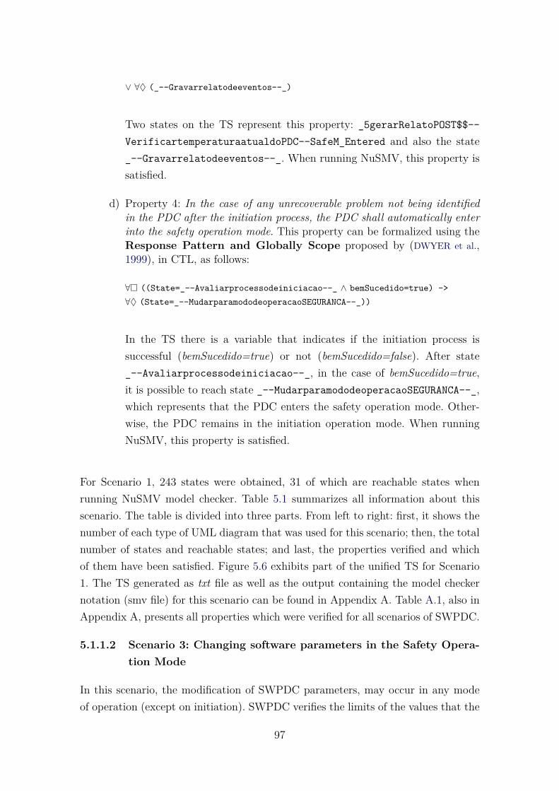
∨ ∀♦ (_--Gravarrelatodeeventos--_)
Two states on the TS represent this property: _5gerarRelatoPOST$$--VerificartemperaturaatualdoPDC--SafeM_Entered and also the state_--Gravarrelatodeeventos--_. When running NuSMV, this property issatisfied.
d) Property 4: In the case of any unrecoverable problem not being identifiedin the PDC after the initiation process, the PDC shall automatically enterinto the safety operation mode. This property can be formalized using theResponse Pattern and Globally Scope proposed by (DWYER et al.,1999), in CTL, as follows:
∀� ((State=_--Avaliarprocessodeiniciacao--_ ∧ bemSucedido=true) ->∀♦ (State=_--MudarparamododeoperacaoSEGURANCA--_))
In the TS there is a variable that indicates if the initiation process issuccessful (bemSucedido=true) or not (bemSucedido=false). After state_--Avaliarprocessodeiniciacao--_, in the case of bemSucedido=true,it is possible to reach state _--MudarparamododeoperacaoSEGURANCA--_,which represents that the PDC enters the safety operation mode. Other-wise, the PDC remains in the initiation operation mode. When runningNuSMV, this property is satisfied.
For Scenario 1, 243 states were obtained, 31 of which are reachable states whenrunning NuSMV model checker. Table 5.1 summarizes all information about thisscenario. The table is divided into three parts. From left to right: first, it shows thenumber of each type of UML diagram that was used for this scenario; then, the totalnumber of states and reachable states; and last, the properties verified and whichof them have been satisfied. Figure 5.6 exhibits part of the unified TS for Scenario1. The TS generated as txt file as well as the output containing the model checkernotation (smv file) for this scenario can be found in Appendix A. Table A.1, also inAppendix A, presents all properties which were verified for all scenarios of SWPDC.
5.1.1.2 Scenario 3: Changing software parameters in the Safety Opera-tion Mode
In this scenario, the modification of SWPDC parameters, may occur in any modeof operation (except on initiation). SWPDC verifies the limits of the values that the
97

Table 5.1 - Statistics about Scenario 1 of SWPDC
UML diagrams Transition System Properties VerifiedSD AD SMD Total States Reachable States Property Satisfied1 1 1 243 31 P1 Yes
P2 YesP3 YesP4 Yes
<(_1powerOn$$--Verificarmemoriadeprograma--PDCOff),bemSucedido=dc,modoIniciacaoPowerOn=dc>
...
<(_2iniciar$$--Verificarmemoriadedados--
IdleANDIniM_POST),bemSucedido=dc,modoIniciacaoPowerOn=dc>
<(_3verificarHardware$$--VerificarstatusdaalimentacaodoPDC--
CountingTimeANDIniM_POST),bemSucedido=dc,
modoIniciacaoPowerOn=dc>
<(_3verificarHardware$$--VerificarstatusdaalimentacaodoPDC--CountingTimeANDSafeM_Entered),
bemSucedido=dc,modoIniciacaoPowerOn=dc>
<(_3verificarHardware$$--VerificarstatusdaalimentacaodoPDC--
SafeM_EnteredANDIdle),bemSucedido=dc,
modoIniciacaoPowerOn=dc>
<(_4obterStatusAlimentacao$HX1-HX2$--VerificarstatusdaalimentacaoEPPHXi--
IniM_POST),bemSucedido=dc,modoIniciacaoPowerOn=dc>
<(_4obterStatusAlimentacao$HX1-HX2$--VerificarstatusdaalimentacaoEPPHXi--SafeM_EnteredANDCountingTime),
bemSucedido=dc,modoIniciacaoPowerOn=dc>
<(_4obterStatusAlimentacao$HX1-HX2$--VerificarstatusdaalimentacaoEPPHXi--SafeM_Entered),bemSucedido=dc,
modoIniciacaoPowerOn=dc>
... ...
......
Figure 5.6 - Part of the unified TS obtained for Scenario 1
parameter in question can assume and proceeds with the change of values in theconfiguration table.
There are two UML diagrams which represent Scenario 3: a sequence and a statemachine diagram, as can be seen in Figures 5.7, 5.8, respectively. Two user-definedproperties for this scenario, related to requirements, were verified.
a) Property 1: The time for generation of housekeeping data can be changedby means of command sent by OBDH. The minimum value of time togenerate housekeeping is 60s, and and the maximum value is 1000s.
98

OBDH : ComOBDH : ConSvcApl : GerEstado :
1: MODIFICAR_PARAMETROS(par,val)
3: COMANDO_RECEBIDO
2: analisarComando()
4: executar(cmd)
5: ok: = consistentir(cmd)
6: [ok] definirManipulador(cmd)
7: manipular(cmd)
8: OK:=verificarLimites(par,val)
9: [OK] alterarParametro(par,val)
Figure 5.7 - Sequence Diagram for Scenario 3
This property can be formalized using the Universality Pattern andGlobally Scope proposed by (DWYER et al., 1999), in CTL, as follows:
∀� (ModifyParameters(HK,60s))∀� (ModifyParameters(HK,1000s))
The state that represents ModifyParamtParameters(HK,60s) is _-$2$dots$__analisarcomando$_$$_$$coma$__ch_sw_par$minus$hk_-60s$slash$cmd_rec__$and$__safem_parhkr$_$, but there is no state inthe TS that represents ModifyParameters(HK,1000s). So, the propertyis not satisfied.
b) Property 2: A session for transmission of housekeeping data begins withthe command PREPARE HOUSEKEEPING DATA. In this case, theSWPDC interrupts the acquisition of scientific data of EPPs. The sessioncontinues with one or more commands TRANSMIT HOUSEKEEPINGDATA (RETRANSMIT RESPONSE, when necessary) and ends with thecommand TRANSMIT SCIENTIFIC DATA, where SWPDC returns toacquire scientific data of EPPs. This property can be formalized using the
99

SafeM_BeginChSw
SafeM_ParHkR
SafeM_ParAnCR
SafeM_WaitHk
SafeM_TxSciR
SafeM_ParHkR2
SafeM_ParAnCR2
SafeM_EndHk
SafeM_PrepHkR
SafeM_TxHkR
NoSeq1
Seq
NoSeq2
Idle
CountingTime
[CH_SW_PAR-Hk_60s/CMD_REC]
[start600s/first]
[CH_SW_PAR-AnC_1000ms/CMD_REC]
[tsinc] [CH_SW_PAR-Hk_600s/CMD_REC]
[TX_DATA-Sci/NO_DATA]
[CH_SW_PAR-AnC_10000ms/CMD_REC]
[PREP_HK/CMD_REC]
[TX_DATA-Hk/HK_DATA_RSC0]
[start60s/sec]
[first]
[sec]
[endtime/tsinc]
Figure 5.8 - State Machine Diagram for Scenario 3
Precedence Chain and Scope After Q proposed by (DWYER et al.,1999), in CTL, as follows:
¬∃[¬ Q ∪ (Q ∧∃ [¬S ∪ P] ∧∃ [¬P ∪ (S ∧ ¬P ∧ ∃© (∃[¬T ∪ (P ∧ ¬T)]))])]where,Q = PREPARE HOUSEKEEPING DATAS = STOP DATA ACQUISITIONT = TRANSMIT HOUSEKEEPING DATAP = TRANSMIT SCIENTIFIC DATA
There are no states in the TS that represent the commands Q, S, T or P.The property is not satisfied.
For Scenario 3, it was obtained 3745 states, 63 of which are reachable states whenrunning NuSMV model checker. Table 5.2 summarizes all information about thisscenario. Figure 5.9 exhibits part of the unified TS for Scenario 3.
100

Table 5.2 - Statistics about Scenario 3 of SWPDC
UML diagrams Transition System Properties VerifiedSD AD SMD Total States Reachable States Property Satisfied1 0 1 3745 63 P1 No
P2 No
<(_1modificar_parametros$par$coma$val$--safem_beginchsw)>
...
<(_2analisarcomando$$--ch_sw_par$minus$hk_60s$slash$cmd_rec
-safem_parhkr$_$)>
<(_4executar$_$cmd$$--first_tseq__and__ch_sw_par$minus$anc_1000ms$slash$cmd_rec
safem_parancr)>
<(_3comando_recebido--ch_sw_par$minus$anc_1000ms$slash$cmd_rec
safem_parancr__and__noseq1$_$)>
<(_4executar$_$cmd$$--start600s$slash$first-safeM_waithk__and__noseq1$_$)>
<(_4executar$_$cmd$$--start600s$slash$first-safeM_waithk__and
first_tseq__)>
...
...
Figure 5.9 - Part of the unified TS obtained for Scenario 3
5.1.1.3 Scenario 8: Housekeeping Data Transmission in the Nominal Op-eration Mode, Robustness (reception), Load new programs
In this scenario, during a sequence of commands for transmission of data, the OBDHmay request the retransmission of the last reply to a request for data. In this case,the command handler defined by the application service control will be responsiblefor acquiring and conditioning the response message to retransmission, working withdata management.
There are four UML diagrams which represent Scenario 8: three sequence diagramsand one state machine diagram, as can be seen in Figures 5.10, 5.11, 5.12, 5.13,
101

respectively. Four user-defined properties for this scenario, related to requirements,were verified.
OBDH : SWPDC :
loop
[]
alt
[]
[]
1: PREPARAR_DADOS(housekeeping)
2: COMANDO_RECEBIDO
5:TRANSMITIR_DADOS(housekeeping)
6: DADOS(housekeeping)
7:TRANSMITIR_DADOS(cientifico)
9: [buffCientificoSuficiente]DADOS (cientifico)
10: [buffCientificoInsuficiente]NENHUM_DADO
3: interromperAquisicaoDeDados
4:prepararDados(housekeeping)
8: iniciarAquisicaoDeDados
Figure 5.10 - Sequence Diagram 1 for Scenario 8
a) Property 1: A session for transmission of housekeeping data begins withthe command PREPARE HOUSEKEEPING DATA. In this case, theSWPDC interrupts the acquisition of scientific data of EPPs. The sessioncontinues with one or more commands TRANSMIT HOUSEKEEPINGDATA (RETRANSMIT RESPONSE, when necessary) and ends with thecommand TRANSMIT SCIENTIFIC DATA, where SWPDC returns toacquire scientific data of EPPs. This property can be formalized using thePrecedence Chain and Scope After Q proposed by (DWYER et al.,1999), in CTL, as follows:
¬∃[¬ Q ∪ (Q ∧∃ [¬S ∪ P] ∧∃ [¬P ∪ (S ∧ ¬P ∧ ∃© (∃[¬T ∪ (P ∧ ¬T)]))])]where,
102

OBDH : SWPDC :
loop
[]
1: PREPARAR_DADOS(tipo)
2: COMANDO_RECEBIDO
5:TRANSMITIR_DADOS(tipo)
6: DADOS(tipo)
timeout
7:RETRANSMITIR_RESPOSTA(tipo)
8:DADOS(tipo)
3: interromperAquisicaoDeDados
4:prepararDados(housekeeping)
Figure 5.11 - Sequence Diagram 2 for Scenario 8
Q = PREPARE HOUSEKEEPING DATAS = STOP DATA ACQUISITIONT = TRANSMIT HOUSEKEEPING DATAP = TRANSMIT SCIENTIFIC DATA
Table 5.3 maps the commands and how they are represented in the TS.When running NuSMV, this property is satisfied.
b) Property 2: The PDC can also have a situation of not receiving thecommand sent. After identifying delimiter of start the PDC waits fora time of 600 ms for the rest of the command. This time is equivalentto 2 times as long to transmit command with maximum size (1128Bytes). In the case of expiry of the stipulated time, a timeout occursand the PDC aborts the communication, the command is discarded,one event is raised to it, and the PDC expects a new command fromOBDH. This property can be formalized using the Precedence Chainand Scope After Q proposed by (DWYER et al., 1999), in CTL, as follows:
¬∃[¬ Q ∪ (Q ∧∃ [¬S ∪ P] ∧∃ [¬P ∪ (S ∧ ¬P ∧ ∃© (∃[¬T ∪ (P ∧ ¬T)]))])]where,Q = StartCommand & Wait600msS = Timeout
103
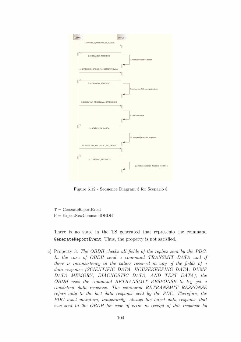
OBDH : SWPDC :
1: PARAR_AQUISICAO_DE_DADOS
2: COMANDO_RECEBIDO
3: parar aquisicao de dados
4: CARREGAR_DADOS_NA_MEMORIA(dados)
5: COMANDO_RECEBIDO
6:[sequencia OK] carregar(dados)
7: EXECUTAR_PROGRAMA_CARREGADO
8: verificar carga
9: STATUS_DA_CARGA
10: [carga ok] executar programa
11: REINICIAR_AQUISICAO_DE_DADOS
12: COMANDO_RECEBIDO
13: iniciar aquisicao de dados (cientifico)
Figure 5.12 - Sequence Diagram 3 for Scenario 8
T = GenerateReportEventP = ExpectNewCommandOBDH
There is no state in the TS generated that represents the commandGenerateReportEvent. Thus, the property is not satisfied.
c) Property 3: The OBDH checks all fields of the replies sent by the PDC.In the case of OBDH send a command TRANSMIT DATA and ifthere is inconsistency in the values received in any of the fields of adata response (SCIENTIFIC DATA, HOUSEKEEPING DATA, DUMPDATA MEMORY, DIAGNOSTIC DATA, AND TEST DATA), theOBDH uses the command RETRANSMIT RESPONSE to try get aconsistent data response. The command RETRANSMIT RESPONSErefers only to the last data response sent by the PDC. Therefore, thePDC must maintain, temporarily, always the latest data response thatwas sent to the OBDH for case of error in receipt of this response by
104

NomM_BeginHkData
NomM_WaitChPar1
NomM_WaitPrepHk1
NomM_EndT1
NomM_WaitT2
Idle
CountingTime
Idle
NomM_WaitPrepHk2
CountingTime
NomM_EndT2 NomM_PrepHkR2
NomM_PrepHkR1 NomM_WaitChPar2
NomM_EndHkData
NomM_WaitT1
NomM_TxHkR1
NomM_TxHkR2
NomM_TxHkR3
NomM_UpPrg
NomM_TxHkR4
NomM_TxHkSqEr
NomM_PrepDmpR1
[VER_OP_MODE/INFO_OP_MODE]
[CH_SW_PAR-Hk_60s/CMD_REC]
[tsinc]
[TX_DATA-Hk/NO_DATA]
[start60s]
[TX_DATA-Sci/SCI_DATA]
[start600s]
[endtime/tsinc]
[tsinc]
[endtime/tsinc]
[PREP_HK/CMD_REC]
[TX_DATA-Hk/timeout]
[TX_DATA-Hk/HK_DATA-RSC0]
[PREP_DMP/CMD_REC]
[PREP_HK/CMD_REC] [CH_SW_PAR-Hk_600s/CMD_REC]
[TX_DATA-Sci/SCI_DATA]
[RET_ANSW/HK_DATA-RSC0]
[UPLOAD_PRG-CSC0-8000H-1113/CMD_REC]
[TX_DATA-Hk/NO_DATA]
[TX_DATA-Hk/NO_DATA]
Figure 5.13 - State Machine Diagram for Scenario 8
the OBDH. The OBDH sends this same command for maximum twomore times. If after these other two attempts still there is problem inthe response received from the PDC, the OBDH does not transmit thiscommand and generates a bug report which should be sent to the groundstation. This property can be formalized using the Precedence Chainand Scope After Q proposed by (DWYER et al., 1999), in CTL, as follows:
¬∃[¬ Q ∪ (Q ∧∃ [¬S ∪ P] ∧∃ [¬P ∪ (S ∧ ¬P ∧ ∃© (∃[¬T ∪ (P ∧ ¬T)]))])]where,Q = TRANSMIT DATA & PDCResponseProblem
105

Table 5.3 - Commands and its representation on the TS
Command TS element Name and/or ValuePREPARE Variable State _$_$1$dots$__preparar_dados$
HOUSEKEEPING DATA _$housekeeping$_$$coma$__1$dots$__preparar_dados$_$tipo$_$$coma$__1$dots$__parar_aquisicao_de_dados
$coma$__nomm_beginhkdata$_$STOP DATA Variable State _$_$3$dots$__interromperaquisicaodedados$
ACQUISITION coma$__3$dots$__interromperaquisicaodedados$coma$__3$dots$__pararaquisicaodedados
$coma$__ch_sw_par$minus$hk_60s$slash$cmd_rec__$and$__nomm_waitt1$_$
TRANSMIT Variable State _$_$5$dots$transmitir_dados$_$housekeepingHOUSEKEEPING DATA $_$$coma$__5$dots$transmitir_dados$_$tipo
$_$$coma$__4$dots$carregar_dados_na_memoria$_$dados$_$$coma$__$minus$$_$
TRANSMIT Variable State _$_$7$dots$transmitir_dados$_$cientificoSCIENTIFIC DATA $_$$coma$__timeout$coma$__6$dots$#
sequenciaok#carregar$_$dados$_$$coma$__$minus$$_$
S = RETRANSMIT RESPONSE 1 & PDCResponseProblemT = RETRANSMIT RESPONSE 2 & PDCResponseProblemP = Stop Sending & GenerateReportEvent
There is no state in the TS generated that represents the command StopSending & GenerateReportEvent. Thus, the property is not satisfied.
d) Property 4: The SWPDC should allow uploading of programs in thisoperation mode. The first command to be sent to the SWPDC is STOPDATA ACQUISITION, for the SWPDC interrupts scientific data acquisi-tion of the EPPs. After this command, one or more commands to LOADDATA MEMORY should be sent to the new program to be loaded in thedata memory of PDC. Later, a command RUN PROGRAM LOADEDINTO MEMORY should be sent to the PDC to have the program loadedto run. At the end of the process of loading and executing of the program,a command RESTART DATA ACQUISITION causes the SWPDC returnto acquire scientific data of EPPs. This property can be formalized usingthe Precedence Chain and Scope After Q proposed by (DWYER etal., 1999), in CTL, as follows:
¬∃[¬ Q ∪ (Q ∧∃ [¬S ∪ P] ∧∃ [¬P ∪ (S ∧ ¬P ∧ ∃© (∃[¬T ∪ (P ∧ ¬T)]))])]where,Q = STOP DATA ACQUISITIONS = LOAD DATA MEMORYT = RUN PROGRAM LOADED
106

P = RESTART DATA ACQUISITION
Table 5.4 maps the commands and how they are represented in the TS.When running NuSMV, this property is satisfied.
Table 5.4 - Commands and its representation on the TS
Command TS element Name and/or ValueSTOP DATA Variable State _$_$3$dots$__interromperaquisicaodedadosACQUISITION $coma$__3$dots$__interromperaquisicaodedados
$coma$__3$dots$__pararaquisicaodedados$coma$__ch_sw_par$minus$hk_60s$slash$
cmd_rec__$and$__nomm_waitt1$_$LOAD DATA Variable State _$_$5$dots$transmitir_dados$_$housekeepingMEMORY $_$$coma$__5$dots$transmitir_dados$_$tipo$_$
$coma$__4$dots$carregar_dados_na_memoria$_$dados$_$$coma$__$minus$$_$
RUN PROGRAM Variable State _$_$8$dots$__iniciaraquisicaodedados$coma$LOADED __7$dots$retransmitir_resposta$_$tipo$_$
$coma$__7$dots$__executar_programa_carregado$coma$__$minus$$_$
RESTART DATA Variable State _$_$8$dots$__iniciaraquisicaodedados$coma$ACQUISITION __8$dots$dados$_$tipo$_$$coma$__11$dots$
reiniciar_aquisicao_de_dados$coma$__$minus$$_$
For Scenario 8, it was obtained 396 states, of which 50 are reachable states whenrunning NuSMV model checker. Table 5.5 summarizes all information about thisscenario. Figure 5.14 exhibits part of the unified TS for Scenario 8.
Table 5.5 - Statistics about Scenario 8 of SWPDC
UML diagrams Transition System Properties VerifiedSD AD SMD Total States Reachable States Property Satisfied3 0 1 396 50 P1 Yes
P2 NoP3 NoP4 Yes
5.1.2 Summary of the results for SWPDC case study
Table 5.6 summarizes the results of all scenarios of SWPDC. It is possible to view thenumber of UML diagrams used for each one of the scenarios. Another informationis the number of states (total and reachable), as well as the number of properties
107

<(_$_$1$dots$__preparar_dados$_$housekeeping$_$
$coma$__1$dots$__preparar_dados$_$tipo$_$$coma$__1$dots$__parar_aquisicao_de_dados
$coma$__nomm_beginhkdata$_$),_condition1=dc, _condition2=dc>
<(_$_$2$dots$__comando_recebido$coma$__2$dots$__comando_recebido$coma$__2$dots$__comando_recebido$coma$
__ver_op_mode$slash$info_op_mode__$and$__nomm_waitchpar1$_$),
_condition1=dc, _condition2=dc>
<(_$_$4$dots$preparardados$_$housekeeping$_$$coma$__4$dots$preparardados$_$housekeeping$_$$coma$__3$dots$__pararaquisicaodedados$coma$
__start600s__$and$__nomm_waitprephk1__and__idle$_$),_condition1=dc, _condition2=dc>
<(_$_$3$dots$__interromperaquisicaodedados$coma$__3$dots$__interromperaquisicaodedados
$coma$__3$dots$__pararaquisicaodedados$coma$__ch_sw_par$minus$hk_60s$slash$
cmd_rec__$and$__nomm_waitt1$_$),_condition1=dc, _condition2=dc>
<(_$_$4$dots$preparardados$_$housekeeping$_$$coma$__4$dots$preparardados$_$housekeeping$_$
$coma$__3$dots$__pararaquisicaodedados$coma$__start600s__$and$__idle$_$)
,_condition1=dc, _condition2=dc>
<(_$_$4$dots$preparardados$_$housekeeping$_$$coma$__4$dots$preparardados$_$housekeeping$_$
$coma$__3$dots$__pararaquisicaodedados$coma$__start600s__$and$__countingtime$_$)
,_condition1=dc, _condition2=dc>
... ...
...
Figure 5.14 - Part of the unified TS obtained for Scenario 8
that were satisfied and not satisfied.
Table 5.6 - Summary of the results of the eight scenarios analyzed for SWPDC
UML Transition System PropertiesScenarios SD AD SMD Total States Reachable States Satisfied Not SatisfiedScenario 1 1 1 1 243 31 4 0Scenario 2 2 0 0 14 14 1 0Scenario 3 1 0 1 3745 63 0 2Scenario 7 1 1 1 3564 54 1 0Scenario 8 3 0 1 396 50 2 2Scenario 9 1 1 1 1377 36 1 0Scenario 10 2 1 1 8262 99 3 0Scenario 12 2 1 1 8262 99 3 0
As it is possible to see, some properties were not satisfied, meaning that some dia-grams do not reflect all the requirements. The main reason for the properties havenot been met, was the absence of states in the TSs that represent certain com-mands/sentences of the properties. This case study was very valuable, because bymeans of the various scenarios, it has enabled to exercise the whole features of
108

SOLIMVA 3.0, which include unifying three or more UML diagrams.
5.2 SWPDCpM - Software for the Payload Data Handling Computer -protoMIRAX experiment
The protoMIRAX is a scientific instrument for observations of x-ray cosmic sources,placed on a stratospheric balloon platform. The main component of protoMIRAX isa camera or, x-ray telescope (CRX). The protoMIRAX balloon gondola will housethe X-ray camera and the various subsystems of the space segment, including theOn-Board Data Handling Subsystem (OBDH), the Attitude Control and PointingSubsystem (ACS), the Flight Control and Telecommunications Subsystem (FCTS),and the Power Supply Subsystem (PSS). Also, there will be a main GPS receiverthat will provide universal time to all subsystems and two star cameras that will bepart of the control loop (BRAGA et al., 2015).
The On-Board Data Handling Subsystem (OBDH; In Portuguese: Subsistema deGestão de Bordo - SGB) processes the information received from the Ground station,as well as gets, generates, formats, stores, and transmits to the Ground station, viaFCTS, information of the subsystems of the experiment protoMIRAX. The mainhardware unit of OBDH is the Payload Data Handling Computer (PDCpM), whichis the on-board computer of OBDH. It is a PC/104 ultra-low-power AMD GeodeLX computer. It operates on 333 MHz, has a 128 MB SDRAM, and has interfacesin addition to analog-digital/digital-analog converters. The software embedded inthe computer (SWPDCpM) has been developed in C language over the real-timeoperating system RTEMS. The architecture of the SWPDCpM is composed of threelayers where the bottom layer is the basic software, the intermediate layer is theflight software library in which there are basic services and reusable components,and the top layer is the application software, the main part of SWPDCpM (BRAGA
et al., 2015). Figure 5.15 shows a simplified physical architecture of the protoMIRAXexperiment with its main subsystems.
In order to apply SOLIMVA 3.0 methodology, the document consulted was theOBDH’s (SGB’s) Software Requirements Specification. This is indeed the SWPD-CpM’s SRS which presents definitions, system environment, software logical model,interfaces, and requirements description, and behavioral modeling by means of UMLsequence diagrams.
In this SRS, one can note that SWPDCpM’s logical model divides the software intothe following application processes which are in fact the main actors of SWPDCpM:
109

RS-422 (115.2 kbps)
PDCpM
GPSDXA
XRC
RS-422 (115.2 kbps)
RS-422 (115.2 kbps)
FCTS
Synchronous (500 kbps)
RS-232 (115.2 kbps)
RS-232 (9.6 kbps)
PSSACS
UNR
OBDH
RS-422(PPS and Data)
OpenCollector
TEMPDXA
RS-422(115.2 kbps)
PRESN
AN
DI(3x)
RS-422(PPS and Data)
RS-422(PPS and Data)
DC-DC Conv
+/- 15 V
UNR
DC-DC Conv
GS
Space Segment
Ground Segment
L-Bandlink
Figure 5.15 - Simplified physical architecture of the protoMIRAX balloon experiment.XRC: X-ray camera; ACS: Attitude Control System; TEMPDXA: Temper-ature monitoring equipment; GPSDXA: GPS unit; OBDH: On-Board DataHandling Subsystem; PDCpM: Payload Data Handling Computer; DC-DCConv: DC-DC Converter; PRESN: Pressure Sensor; PSS: Power Supply Sub-system; FCTS: Flight Control and Telecommunications Subsystem. Braga etal. (2015)
a) CTL: SWPDCpM general control and transfer of packages;
b) HK: Internal housekeeping data collection of SWPCpM;
c) SYN: Clock synchronization and maintenance of mission time;
d) SCA: Interface control of data packets with SCA;
e) CRX: Interface control of data packets with CRX;
f) AP: Generic application process, both on board and in the ground;
g) ESS: An application process of the ground station.
110

5.2.1 Scenarios of SWPDCpM
In the case study, twelve scenarios of SWPDCpM were carried out.
a) Scenario 1: Receive Telecommand;
b) Scenario 2: Submit Telecommand;
c) Scenario 3: Submit Telemetry;
d) Scenario 4: Enable/Disable Telemetry Sending;
e) Scenario 5: Report Computer Operation Mode;
f) Scenario 6: Changing Computer Operation Mode;
g) Scenario 7: Distribute Commands On and Off;
h) Scenario 8: Control of Dump Memory Process;
i) Scenario 9: Report Software Current Version;
j) Scenario 10: Report Charge State of a New Version;
k) Scenario 11: Start New Version Loading;
l) Scenario 12: Control Interfaces with SCA.
As for SWPDC, the next subsections detail three of the twelve scenarios of SWPD-CpM (scenarios 6, 7, and 8). Subsection 5.2.2 summarizes the results obtained fromall the scenarios analyzed.
5.2.1.1 Scenario 6: Changing Computer Operation Mode
In order to control the computer operation mode, the CTL process should: controlthe switching between computer operation modes of SWPDCpM; and allow to con-sult the current computer operation mode. There is one UML sequence diagramwhich represents Scenario 6. It is shown in Figure 5.16.
Observe the following requirement related to this scenario: Upon receipt of a TCfrom CTL.TC requesting the change of computational operation mode, the CTL pro-cess should proceed the following sequence of operations: 1) To obtain new computeroperation mode from TC and to perform mode changing by issuing internal com-mands; 2) If the computer operation mode can not be changed, a TM_RE must be
111
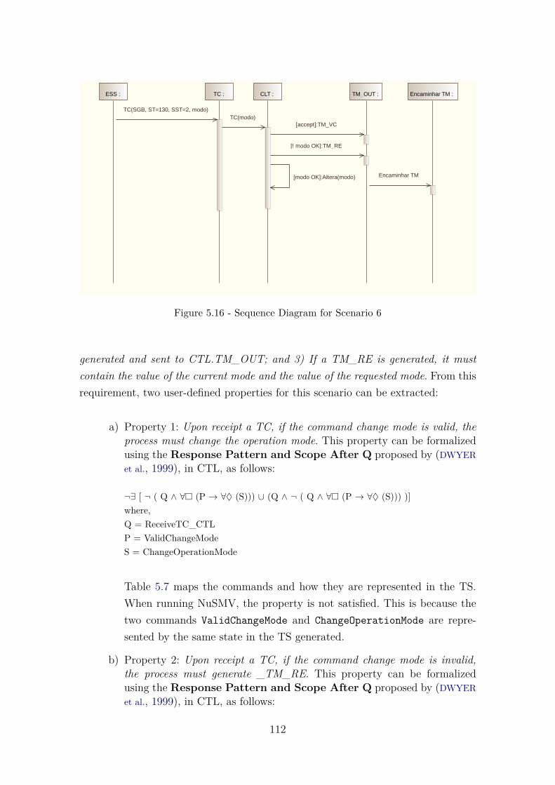
ESS : TC : CLT : TM_OUT : Encaminhar TM :
TC(SGB, ST=130, SST=2, modo) TC(modo)
[accept]:TM_VC
[! modo OK]:TM_RE
[modo OK]:Altera(modo) Encaminhar TM
Figure 5.16 - Sequence Diagram for Scenario 6
generated and sent to CTL.TM_OUT; and 3) If a TM_RE is generated, it mustcontain the value of the current mode and the value of the requested mode. From thisrequirement, two user-defined properties for this scenario can be extracted:
a) Property 1: Upon receipt a TC, if the command change mode is valid, theprocess must change the operation mode. This property can be formalizedusing the Response Pattern and Scope After Q proposed by (DWYERet al., 1999), in CTL, as follows:
¬∃ [ ¬ ( Q ∧ ∀� (P → ∀♦ (S))) ∪ (Q ∧ ¬ ( Q ∧ ∀� (P → ∀♦ (S))) )]where,Q = ReceiveTC_CTLP = ValidChangeModeS = ChangeOperationMode
Table 5.7 maps the commands and how they are represented in the TS.When running NuSMV, the property is not satisfied. This is because thetwo commands ValidChangeMode and ChangeOperationMode are repre-sented by the same state in the TS generated.
b) Property 2: Upon receipt a TC, if the command change mode is invalid,the process must generate _TM_RE. This property can be formalizedusing the Response Pattern and Scope After Q proposed by (DWYERet al., 1999), in CTL, as follows:
112

Table 5.7 - Commands and its representation on the TS
Command TS element Name and/or ValueReceiveTC_CTL Variable State _tc$_$sgb$coma$__st$equals$130$coma$__
sst$equals$2$coma$__modo$_$ValidChangeMode Variable State _#modo__ok#$dots$altera$_$modo$_$
ChangeOperationMode Variable State _#modo__ok#$dots$altera$_$modo$_$
¬∃ [ ¬ ( Q ∧ ∀� (P → ∀♦ (S))) ∪ (Q ∧ ¬ ( Q ∧ ∀� (P → ∀♦ (S))) )]where,Q = ReceiveTC_CTLP = InvalidChangeModeS = Generate_TM_RE
Table 5.8 maps the commands and how they are represented in the TS.When running NuSMV, the property is not satisfied. This is because thetwo commands InvalidChangeMode and Generate_TM_RE are representedby the same state in the TS generated.
Table 5.8 - Commands and its representation on the TS
Command TS element Name and/or ValueReceiveTC_CTL Variable State _tc$_$sgb$coma$__st$equals$130$coma$__
sst$equals$2$coma$__modo$_$InvalidChangeMode Variable State _#$not$__modo__ok#$dots$tm_reGenerate_TM_RE Variable State _#$not$__modo__ok#$dots$tm_re
For Scenario 6, it was obtained 6 states, of which 6 are reachable states when runningNuSMV model checker. Table 5.9 summarizes all information about this scenario.Figure 5.17 exhibits the unified TS for Scenario 6. The TS generated as txt file aswell as the output containing the model checker notation (smv file) for this scenariocan be found in Appendix B. Table B.1, also in Appendix B, presents all propertieswhich were verified for all scenarios of SWPDCpM.
Table 5.9 - Statistics about Scenario 6 of SWPDCpM
UML diagrams Transition System Properties VerifiedSD AD SMD Total States Reachable States Property Satisfied1 0 0 6 6 P1 No
P2 No
113

<(_tc$_$sgb$coma$__st$equals$130$coma$__sst$equals$2$coma$__modo$_$)>
<(_tc$_$modo$_$)>
<(_#$not$__modo__ok#$dots$tm_re)>
<(_#accept#$dots$tm_vc)>
<(_#modo__ok#$dots$altera$_$modo$_$)>
<( _encaminhar__tm)>
Figure 5.17 - The unified TS obtained for Scenario 6
5.2.1.2 Scenario 7: Distribute Commands On and Off
In this scenario the CTL process must distribute commands on and off required byTC. There is one UML sequence diagram which represents Scenario 7. It is shownin Figure 5.18.
Observe the following requirement related to this scenario: The CTL process shoulddistribute commands on/off requested by TC. The following sequence of operationsmust be performed: 1) Get command word on/off of the input TC; 2) Acting inhardware to perform the commands on/off through the CTL.ON_OFF_TC inter-face. This requirement is represented by the following property:
a) Property 1: This property can be formalized using the PrecedencePattern and Scope After Q proposed by (DWYER et al., 1999), in CTL,as follows:
¬∃ [ ¬ (Q ∧ (¬∃ [ ¬ S ∪ (P ∧ ¬ S)]) ) ∪ ( Q ∧ ¬ (Q ∧ (¬∃ [ ¬ S ∪ (P ∧ ¬S)]) ) )]where,Q = ReceiveTC_CTLP = ObtainwordOnOffS = ActingHardware_CTL.ON_OFF_TC
114

ESS : TC : ON_OFF_TC : CTL : TM_OUT : Encaminhar TM :
T C(SGB, ST=2, SST=1, endereço)
TC(endereço)
[accept]:TM_VC
[endereço inválido]:TM_RE
[endereço válido]:traduz(endereço) :sinal Encaminhar TM
cmd_puso(sinal)
Figure 5.18 - Sequence Diagram for Scenario 7
Table 5.10 maps the commands and how they are represented in the TS.When running NuSMV, the property is satisfied.
Table 5.10 - Commands and its representation on the TS
Command TS element Name and/or ValueReceiveTC_CTL Variable State _tc$_$endereco$_$ObtainwordOnOff Variable State _#endereco__valido#$dots
$traduz$_$endereco$_$__$dots$sinalActingHardware_CTL.ON_OFF_TC Variable State _cmd_pulso$_$sinal$_$
For Scenario 7, it was obtained 7 states, of which 7 are reachable states when runningNuSMV model checker. Table 5.11 summarizes all information about this scenario.Figure 5.19 exhibits the unified TS for Scenario 7.
Table 5.11 - Statistics about Scenario 7 of SWPDCpM
UML diagrams Transition System Properties VerifiedSD AD SMD Total States Reachable States Property Satisfied1 0 0 7 7 P1 Yes
115

<(_t__c$_$sgb$coma$__st$equals$2$coma$__sst$equals$1$coma$__endereco$_$)>
<(_tc$_$endereco$_$)>
<(_#endereco__invalido#$dots$tm_re)><(_#accept#$dots$tm_vc)>
<(_#endereco__valido#$dots$traduz$_$endereco$_$__$dots$sinal)>
<(_encaminha__tm)>
<(_cmd_puso$_$sinal$_$)>
Figure 5.19 - The unified TS obtained for Scenario 7
5.2.1.3 Scenario 8: Control of Dump Memory Process
The CTL process should control the dump memory when requested by the groundstation. There is one UML sequence diagram which represents Scenario 8. It is shownin Figure 5.20. Two user-defined properties for this scenario, related to requirements,were verified.
a) Property 1: This function meets the telecommand of memory dumprequest. The following sequence of operations must be performed: 1)Get address and memory size required for dump; 2) Copy memory todumpfile CTL.MMFS, reporting the progress of the operation throughTM_VC, up to a maximum of 4MB; 3) Start transfer process of filegenerated in CTL.MMFS. Report TM_RE and ignore the request when:4) The requested memory is invalid; 5) The requested size exceeds themaximum dump capacity; 6) A memory transfer process is still inprogress. This property can be formalized using the Precedence Chainand Scope After Q proposed by (DWYER et al., 1999), in CTL, as follows:
¬∃[¬ Q ∪ (Q ∧∃ [¬S ∪ P] ∧∃ [¬P ∪ (S ∧ ¬P ∧ ∃© (∃[¬T ∪ (P ∧ ¬T)]))])]where,Q = ReceiveTC_CTL.TC_DumpMemory
116

ESS : TC : MMFS : CTL : TM_OUT :
loop
[OK == TRUE]
Encaminhar TM :
TC(SGB, ST=6, SST=5, endereço, tamanho)
TC(endereço, tamanho)
[accept]:TM_VC
Validar(endereço, tamanho) :O
[!OK]:TM_RE
Dump(endereço, tamanho) :blocos[]
gerar(dumpfile, blocos[]) :OK
[!OK]:TM_RE
ler(dumpfile) :bloco
TM_DM(bloco)
aguardar(250ms)
apagar(dumpfile) Encaminhar TM
Figure 5.20 - Sequence Diagram for Scenario 8
S = GetAddressMemorySizeT = (¬(InvalidMemory ∨ InvalidSize ∨ ProcessTransferProgress) → (CopyMemory-Dumpfile → Forward_TM_VC))P = StartTransferDumpFile
There is no state in the TS that represents the commandProcessTransferProgress. The property is not satisfied.
b) Property 2: This process is initiated by CTL automatically when adumpfile file is generated in CTL.MMFS. The following operation mustbe done in parallel with other software functions: 1) Generate TM_DMpackages limited by the maximum size set to a TM package, consider-ing that the last TM_DM package may have a size less than or equalto the maximum size of a packet TM; 2) Send TM_DM packages toCTL.TM_OUT at a rate not greater than four packets per second;3) Report TM_VC indicating the completion status of the operation;4) Delete dumpfile when finished. Report TM_RE and cancel transferprocess when: 5) Occur I/O error in dumpfile; 6) A change occurs forcomputer mode operation that does not allow dump memory during dumpprocess. This property can be formalized using the Precedence Chainand Scope After Q proposed by (DWYER et al., 1999), in CTL, as follows:
¬∃[¬ Q ∪ (Q ∧∃ [¬S ∪ P] ∧∃ [¬P ∪ (S ∧ ¬P ∧ ∃© (∃[¬T ∪ (P ∧ ¬T)]))])]where,
117

Q = DumpFileGeneratedS = (¬(ErrorIODumpFile ∨ ChangeOperationModeNDump) → GeneratePackageDM)T = SendPackagesTM_DM_CTL.TM_OUTP = (Report_TM_VC → DeleteDumpFile)
There is no state in the TS that represents the commandChangeOperationModeNDump. The property is not satisfied.
For Scenario 8, it was obtained 36 states, of which 16 are reachable states whenrunning NuSMV model checker. Table 5.12 summarizes all information about thisscenario. Figure 5.21 exhibits part of the unified TS for Scenario 8.
Table 5.12 - Statistics about Scenario 8 of SWPDCpM
UML diagrams Transition System Properties VerifiedSD AD SMD Total States Reachable States Property Satisfied1 0 0 36 16 P1 No
P2 No
<(_tc$_$sgb$coma$__st$equals$6$coma$__sst$equals$5$coma$__endereco$coma$
__tamanho$_$), _ok=dc>
<(_tc$endereco$coma$__tamanho$_$), _ok=dc>
<(_validar$_$endereco$coma$__tamanho$_$__$dots$ok), _ok=dc>
<(_#accept#$dots$tm_vc), _ok=dc>
<(_#$not$ok#$dots$tm_re), _ok=dc>
<(_dump$_$endereco$coma$__tamanho$_$__$dots$blocos##), _ok=dc>
<(_gerar$_$dumpfile$coma$__blocos##$_$__$dots$ok), _ok=dc>
<(_#$not$ok#$dots$tm_re), _ok=dc>
...
Figure 5.21 - Part of the unified TS obtained for Scenario 8
118

5.2.2 Summary of the results of SWPDCpM
Table 5.13 summarizes the results of all scenarios of SWPDCpM. It has the sameinformation of the previous summarized table of case study SWPDC: number ofUML diagrams used for each one of the scenarios, number of states (total andreachable), as well as the number of properties that were satisfied and not satisfied.
Table 5.13 - Summary of the results of the twelve scenarios analyzed for SWPDCpM
UML Transition System PropertiesScenarios SD AD SMD Total States Reachable States Satisfied Not SatisfiedScenario 1 1 0 0 15 7 2 0Scenario 2 1 0 0 7 7 0 7Scenario 3 1 0 0 27 11 2 0Scenario 4 1 0 0 6 6 1 0Scenario 5 1 0 0 5 5 1 0Scenario 6 1 0 0 6 6 0 2Scenario 7 1 0 0 7 7 1 0Scenario 8 1 0 0 36 16 0 2Scenario 9 1 0 0 6 6 1 0Scenario 10 1 0 0 7 7 1 0Scenario 11 1 0 0 7 7 1 0Scenario 12 1 0 0 4 3 2 0
As it is possible to see, almost half of the properties were not satisfied, meaning thatsome diagrams do not meet all the requirements. Although this case study has onlysequence diagrams, and thus it is not possible to exercise the whole features (whichincludes unifying the three UML diagrams) of SOLIMVA 3.0, this case study is veryimportant because it is a complex space application under development at INPE.The results of using SOLIMVA 3.0 to analyze the (partial) design of SWPDCpMhave already been communicated to the OBDH (SGB) development team.
The properties were not satisfied because it was not found states that could repre-sent some commands or sentences present in the properties, and also because somecommands or sentences were represented by one unique state in the TS.
5.3 Final Remarks
This chapter presented the application of SOLIMVA 3.0 to two case studies, SWPDCand SWPDCpM, related to an X-ray imaging balloon experiment under develomentat INPE. Defects were detected within the design of these software systems showingthe feasibility of the methodology.
119

The case studies were conducted considering twenty scenarios: eight from SWPDCand twelve from SWPDCpM. For the eight scenarios of SWPDC, a total of nineteenproperties were verified. Of these, fifteen were satisfied and four were not satisfied.This means that in 21.05% of the properties, the design of the SWPDC, by meansof its UML diagrams, were not correct. For the twelve scenarios of SWPDCpM, atotal of twenty three properties were verified. Of these, twelve were satisfied andeleven were not. Thus, for SWPDCpM, 47.83% of the properties were not satisfied.This is a significant defect detection in the (partial) design of the SWPDCpM.
It is important to know why the design (UML) did not satisfy the properties. Thus,an analysis of the causes of the defects found was performed. For SWPDC, it wasalways the same reason: there is no state in the TS that represents a certain com-mand. This means that some commands are omitted or do not exist in the diagrams.For SWPDCpM, the defects occurred due to: (i) there is no state in the TS thatrepresents a certain command; (ii) two commands are represented by the same statein the TS. So, the property can not be specified. Table 5.14 shows the causes andthe number of properties which were not satisfied due to each cause, for the twocase studies.
Table 5.14 - Causes for encountered defects
(i) there is no state in the TS (ii) two commands are representedthat represents a certain command by the same state in the TS
SWPDC 4 0SWPDCpM 5 6
Considering that, it is exposed the importance of the approach based on FormalVerification to improve the quality of embedded software development for INPE’sspace projects. The results show the potential for a wide acceptance of FormalVerification for the development of complex software systems.
The next chapter presents the contributions obtained in this work, as well as itslimitations and future prospects of this research.
120

6 CONCLUSIONS AND FINAL REMARKS
INPE deals with critical embedded software in satellites and stratospheric baloons.Critical systems require high reliable software. A challenge in the systems develop-ment process is to advance defect detection at early stages of their life cycles. V&Vtechniques are essential to provide quality to the software systems being developed.Formal Methods, such as Model Checking, offer a large potential to provide effectiveverification techniques. However, Formal Methods require mathematical backgroundand their use is restricted, as users privilege the simplicity of other notations, ratherthan more formal means.
In this line, many studies have emerged in order to develop approaches that allowthe use of Formal Methods in a manner that is transparent to the user. One suchexample is the translation of industry non-formal standards such as UML to modelcheckers notation, considered as a great step towards a wide acceptance of FormalMethods in every day software development (SANTIAGO JÚNIOR, 2011).
Despite criticism regarding UML, it is indeed used in practice in many applicationdomains. Modeling systems for object oriented and/or embedded software devel-opment is an approach that has been employed by researchers and practitioners,specially by means of the several UML behavioral diagrams.
In order to cover these two domains, taking advantage of the positive aspects ofboth, this PhD thesis proposed the SOLIMVA 3.0 methodology (SANTOS et al.,2014a),(SANTOS et al., 2014b),(ERAS et al., 2015), aiming to transform a non-formallanguage (UML) to a formal language (language of a model checker) in order to de-tect defects within the design of the software product. SOLIMVA 3.0 is an extensionof a methodology initially developed to generate model-based system and acceptancetest cases considering Natural Language requirements artifacts (SOLIMVA 1.0), andto detect incompleteness in software specifications by means of Model Checking(SOLIMVA 2.0). By including Formal Verification in the SOLIMVA methodology,the V&V process is enriched, addressing not only testing and inspection but alsoFormal Verification.
The approach proposed in SOLIMVA 3.0 considers the properties generated fromUML use case models or requirements expressed in pure textual notation (NaturalLanguage), and the Transition System translated from up to three UML behavioraldiagrams: sequence, activity, and behavioral state machine. Then, Model Checkingcan be used to ensure that the behavior of the system satisfies the requirements,
121

that is, whether the properties are satisfied by the Transition System that representsthe behavior of the application under evaluation. Using more than one diagramprovides a rich view of the system by different angles or in different states in time.It also helps to find inconsistencies and incompleteness in the models by confrontingmultiple views of the same system.
Additionally, a tool, XMITS, was developed to automate some steps of SOLIMVA3.0 methodology. XMITS performs a three-step translation. First, it translates in-dividual types of diagrams into a TS in a simple intermediate format. After that,XMITS merges all single TSs into a unified TS. Finally, the tool transforms thisunified TS into the notation of the model checker (NuSMV).
Briefly, the process proposed in SOLIMVA 3.0 is as follows: first, scenarios are iden-tified to be checked (scenarios are checked one by one). These scenarios have certainproperties that must be verified. These properties are extracted from UML use casemodels or simply in Natural Language. SOLIMVA 3.0 suggests using specificationpatterns (DWYER et al., 1999) to direct the formalization of properties in Compu-tation Tree Logic (BAIER; KATOEN, 2008). The UML diagrams that are related tothe scenario that is being checked are input to XMITS. Hence, XMITS automat-ically generates a single, unified TS in the notation of the NuSMV model checker(KESSLER, 2015). By running NuSMV it is possible to observe if there are defectsin the design of the software product. In case the TS does not satisfy a certainproperty, a counterexample is presented by the model checker. In the whole process,three tools are used: Modelio, to generate the UML diagrams and export them toXMI format; XMITS (which was developed to support this PhD thesis), that trans-forms the UML to the input language of the model checker; and NuSMV, which isthe model checker used to perform the Model Checking.
SOLIMVA 3.0 was applied to two real space software products (embedded software),SWPDC and SWPDCpM in order to validade the methodology. These software sys-tems are related to the balloon-borne high energy astrophysics experiment calledprotoMIRAX under development at INPE. Defects were detected within the designof these software systems, what shows that the methodology can be applied in prac-tice. Specifically, 21.05% and almost 50% of the properties formalized in CTL werenot satisfied for the SWPDC and SWPDCpM case studies, respectively. This impliesthat there are design flaws related to the conception of these software systems. Thedefects encountered were due to issues such as it was not found states that couldrepresent some commands or sentences present in the properties, and also because
122

some commands or sentences were represented by one unique state in the TS. Theresults show the potential for the use of an approach based on Formal Verification toimprove the quality of embedded software development for critical INPE projects.
Regarding to the case studies, twenty scenarios were checked: eight from SWPDCand twelve from SWPDCpM. For SWPDC, nineteen properties were verified, andfour of them were not satisfied, i.e., the design artifacts do not reflect the require-ments related to these properties. For SWPDCpM, twenty three properties wereverified. Of these, eleven were not satisfied, which is a significant defect detection inthe design of SWPDCpM. These results analyzing the (partial) design of SWPDCpMhave already been communicated to the OBDH (SGB) development team.
The main contribution of this PhD thesis is to help to make it easier the use of FormalVerification process for critical space software towards a greater adoption in practiceof Formal Methods in software development. When compared to some other researchstudies, (MIKK et al., 1998),(LATELLA et al., 1999),(KONRAD; CHENG, 2006),(LAM,2007),(ESHUIS, 2006),(ANDERSON et al., 1996),(DUBROVIN; JUNTTILA, 2008),(UCHI-
TEL; KRAMER, 2001),(BARESI et al., 2011),(MIYAZAWA et al., 2013),(BEATO et al.,2005),(CORTELLESSA; MIRANDOLA, 2002),(MERSEGUER et al., 2002), SOLIMVA 3.0has the following advantages:
a) it uses different behavioral diagrams, when most of the studies use onlyone single diagram;
b) it detects design defects considering functional requirements of the softwareproduct, when some researches focus on specific types of requirements, suchas performance;
c) it demands only behavioral diagrams, that are often present in softwaredocumentation, when other works require a very large amount of artifacts,including for example, structural and behavioral diagrams.
A qualitative comparison between the SOLIMVA 3.0 methodology and other sev-eral approaches was presented in Section 2.5. Although a quantitative comparisonbetween SOLIMVA 3.0 and these other approaches has not been made, it is veryimportant to remark:
a) SOLIMVA 3.0 methodology was applied to two real and complex casestudies of the space domain. In both case studies, there was involvement
123
of the software national industry. The academic community has long beencharged to reverse their knowledge to the industry and research institutes(such as INPE) so that these organizations can use such knowledge tothe development of their systems. By using real and complex case studies,SOLIMVA 3.0, supported by the XMITS tool, is in agreement with thisperspective allowing that an informal language (UML), still quite popular,can continue to be used for creating the design of software systems. Thecomplexity for the use of formal methods (Model Checking, in this case)is almost completely hidden from the practitioner, and thus SOLIMVA3.0 methodology has a high potential to be applied to the development ofother highly complex software systems.
b) The software design developed for both case studies had already been as-sessed by experienced professionals in the context of their respective sys-tem/software development lifecycle and formal technical reviews. Findingadditional defects within these design solutions, even if practitioners inthe field have evaluated them, demonstrates the real usefulness of thisPhD thesis.
6.1 Limitations
There are some limitations in SOLIMVA 3.0, of which stand out:
a) One of the main difficulties when working with Model Checking is theformalization of properties. SOLIMVA 3.0 has proposed a solution for au-tomating the model generation. However, the properties still have to bemanually formalized. A study about automated property formalization,specially if requirements are expressed in Natural Language, is importantto be carried out.
b) Another restriction is related to counterexample. How to find the diagramand the exact point in this diagram where the property was not satisfied?The automated translation of the model checker counterexample back tothe UML diagrams is important to identify in which diagram, or diagrams,the detected problem is related.
6.2 Suggestions for Future Research
To solve the limitations presented above, the following list of future work is proposed:
124

a) Directives to improve the automation of property formalization or facilitatethis formalization is important to be addressed.
b) Another important future work is the development of a new module ofXMITS to catch the feedback from NuSMV and show to the user theresults automatically.
In addition, the following other suggestions can be listed:
a) It is important to define a more detailed formal semantics for the transla-tion from UML to TS proposed by SOLIMVA 3.0.
b) One other interesting new feature could be the implementation of newUML diagrams compatibility. The Converter module of XMITS is readyto accept new UML diagrams by adding a new collector class.
c) A subset of the UML diagrams syntax is implemented in XMITS. Thereare several other features not supported by XMITS in the current version.To increase this subset also increases the possibility of the tool use.
d) NuSMV is the only model checker used in XMITS. New grammars can bedefined so that other model checkers, such as SPIN, may be used.
e) The current ouput of TUTS module is a txt file, showing all states. It isnot possible to see the TS tree, following the flow of transitions. Addingan output in graph format, showing states and transitions would help andfacilitate the validation of the TS.
f) Regarding to parallelism, when a process is divided due to parallel mes-sages/activities/states, each process goes on alone. In many cases, thereare states that are created in each one of these processes that are the same,that is, repeated states. Sometimes this led to not run some scenarios, es-pecially those with many cases of parallelism. A method in XMITS thatseeks for repeated states during the process of creation of the TS is miss-ing. Thus, it is relevant to improve the tool with such a method to dealwith state space explosion.
125

REFERENCES
AMJAD, H. Combining model checking and theorem proving. Cambridge,United Kingdom, 2004. 131p. Technical Report. 18, 19
ANDERSON, R. J.; BEAME, P.; BURNS, S.; CHAN, W.; MODUGNO, F.;NOTKIN, D.; REESE, J. D. Model checking large software specifications. ACMSIGSOFT Software Engineering Notes, v. 21, p. 156–166, 1996. 4, 6, 32, 36,39, 123
BAIER, C.; KATOEN, J.-P. Principles of model checking. Cambridge, MA,USA: MIT Press, 2008. 975 p. Available from:<http://mitpress.mit.edu/books/principles-model-checking>. xv, 1, 3, 5,18, 19, 20, 24, 27, 45, 64, 71, 122
BARESI, L.; MORZENTI, A.; MOTTA, A.; ROSSI, M. Towards the uml-basedformal verification of timed systems. Formal Methods for Components andObjects, v. 6957, p. 267–286, 2011. 6, 34, 36, 39, 123
BEATO, M. E.; BARRIO-SOLÓRZANO, M.; CUESTA, C. E.; FUENTE, P. de la.Uml automatic verification tool with formal methods. Electronic Notes inTheoretical Computer Science, Elsevier, v. 127, n. 4, p. 3–16, 2005. 6, 35, 36,123
BEHRMANN, G.; DAVID, A.; LARSEN, K. A tutorial on uppaal. Formalmethods for the design of real-time systems, Springer, v. 3185, p. 200–236,2004. 26
BJORK, R. C. The simulation of an automated teller machine. 2012.Available from:<http://www.math-cs.gordon.edu/courses/cs211/ATMExample/>. Access in:11 mai. 2014. 43
BOEHM, B. Software engineering economics. 1. ed. US: Prentice Hall, 1981. 9
BRAGA, J.; D’AMICO, F.; AVILA, M. A. C.; PENACCHIONI, A. V.; SACAHUI,J. R.; SANTIAGO, V. A. de; MATTIELLO-FRANCISCO, F.; STRAUSS, C.;FIALHO, M. A. A. The protomirax hard x-ray imaging balloon experiment.A&A, v. 580, p. A108, 2015. Available from:<http://dx.doi.org/10.1051/0004-6361/201526343>. xvi, 5, 109, 110
127

BRIAND, L.; LABICHE, Y. A uml-based approach to system testing. Softwareand Systems Modeling, Springer, v. 1, n. 1, p. 10–42, 2002. 31, 36
BRITO, P. H. S.; LEMOS, R. D.; RUBIRA, C. M. F.; MARTINS, E. Architectingfault tolerance with exception handling: verification and validation. J. Comput.Sci. Technol., Institute of Computing Technology, Beijing, China, v. 24, n. 2, p.212–237, mar. 2009. ISSN 1000-9000. Available from:<http://dx.doi.org/10.1007/s11390-009-9219-2>. 31, 36, 39
CAVADA, R.; CIMATTI, A.; JOCHIM, C. A.; KEIGHREN, G.; OLIVETTI, E.;PISTORE, M.; ROVERI, M.; TCHALTSEV, A. NuSMV 2.5 user manual.2005. Available from: <http://nusmv.fbk.eu/>. Access in: 12 mai. 2013. 66
CHEN, M.; MISHRA, P.; KALITA, D. Coverage-driven automatic test generationfor uml activity diagrams. In: ACM GREAT LAKES SYMPOSIUM ON VLSI, 18.,2008, Orlando, Florida, USA. Proceedings... New York, NY, USA: ACM, 2008.p. 139–142. ISBN 978-1-59593-999-9. 477088. 31, 36
CLARKE, E. The birth of model checking. 25 Years of Model Checking,Springer, v. 5000, p. 1–26, 2008. 22
CLARKE, E. M.; EMERSON, E. A. Design and synthesis of synchronizationskeletons using branching time temporal logic. In: GRUMBERG, O.; VEITH, H.(Ed.). 25 years of model checking. Berlin/Heidelberg, Germany: SpringerBerlin/Heidelberg, 2008. v. 5000, p. 196–215. Lecture Notes in Computer Science(LNCS). 3, 19
CLARKE, E. M.; GRUMBERG, O.; PELED, D. Model checking. Cambridge -MA: MIT press, 1999. ISBN 978-0262032704. 1
COCKBURN, A. Writing effective use cases. US: Addison-Wesley Professional,2000. 304 p. 11, 43
CORTELLESSA, V.; MIRANDOLA, R. Prima-uml: a performance validationincremental methodology on early uml diagrams. SC Programming, Elsevier,v. 44, n. 1, p. 101–129, 2002. 6, 34, 36, 123
DEBBABI, M.; HASSAÏNE, F.; JARRAYA, Y.; SOEANU, A.; ALAWNEH, L.Verification and validation in systems engineering. Berlin, Heidelberg -Germany: Springer, 2010. 270 p. xv, 4, 63, 74
DELAMARO, E.; MALDONADO, J. C.; M., J. Introdução ao teste desoftware. Rio de Janeiro: Ed. Elsevier, 2007. 1
128

DUBROVIN, J.; JUNTTILA, T. Symbolic model checking of hierarchical umlstate machines. In: INTERNATIONAL CONFERENCE ON APPLICATION OFCONCURRENCY TO SYSTEM DESIGN, 8., 2008, Xi’An - China.Proceedings... Xi’An - China: IEEE, 2008. p. 108–117. ISBN 978-1-4244-1838-1.4, 6, 32, 36, 39, 123
DWYER, M. B.; AVRUNIN, G. S.; CORBETT, J. C. Patterns in propertyspecifications for finite-state verification. In: INTERNATIONAL CONFERENCEON SOFTWARE ENGINEERING, 21., 1999, Los Angeles, CA, USA.Proceedings... New York, NY, USA: ACM, 1999. p. 411–420. ISBN1-58113-074-0. 5, 24, 31, 44, 64, 72, 73, 78, 94, 96, 97, 99, 100, 102, 103, 105, 106,112, 114, 116, 117, 122
ECLIPSE.ORG. Papyrus. 2014. Available from:<https://www.eclipse.org/papyrus/>. Access in: 19 jan. 2014. 161
ERAS, E. R.; SANTOS, L. B. R. dos; JÚNIOR, V. A. de S.; VIJAYKUMAR,N. L. Towards a wide acceptance of formal methods to the design of safety criticalsoftware: an approach based on uml and model checking. Lecture Notes inComputer Science, v. 9158, p. 612–627, 2015. 4, 5, 77, 121
ESHUIS, R. Symbolic model checking of uml activity diagrams. ACMTransactions on Software Engineering and Methodology (TOSEM),ACM, v. 15, n. 1, p. 1–38, 2006. 4, 6, 32, 36, 123
FRASER, G.; WOTAWA, F.; AMMANN, P. Testing with model checkers: asurvey. Software Testing, Verification and Reliability, Wiley Online Library,v. 19, n. 3, p. 215–261, 2009. 22, 25
GANAI, M.; GUPTA, A. SAT-based scalable formal verification solutions.Princeton - US: Springer, 2007. 2, 17
GILB, T.; GRAHAM, D.; FINZI, S. Software inspection. London - UK:Addison-Wesley Longman Publishing Co., Inc., 1993. ISBN 078-5342631814. 1
GODBOLE, N. S. Software quality assurance: principles and practice. Oxford,UK: Alpha Science International, 2006. 1
HAREL, D. Statecharts: A visual formalism for complex systems. Science ofcomputer programming, Elsevier, v. 8, n. 3, p. 231–274, 1987. 3
129

HARTMANN, J.; VIEIRA, M.; FOSTER, H.; RUDER, A. A uml-based approachto system testing. Innovations in Systems and Software Engineering,Springer, v. 1, n. 1, p. 12–24, 2005. 31, 36
HOLZMANN, G. The SPIN model checker: primer and reference manual.Boston - MA: Addison-Wesley, 2004. 25, 63
IEEE. Institute of electric and electronic engineers. Standard glossary ofsoftware engineering terminology, Standard 610.12, 1990. 1, 2, 9, 10
JOHNSON, K.; CALINESCU, R.; KIKUCHI, S. An incremental verificationframework for component-based software systems. In: INTERNATIONAL ACMSIGSOFT SYMPOSIUM ON COMPONENT-BASED SOFTWAREENGINEERING, 16., 2013. Proceedings... New York, NY, USA: ACM, 2013. p.33–42. ISBN 978-1-4503-2122-8. 33
JÚNIOR, V. A. d. S.; CRISTIÁ, M.; VIJAYKUMAR, N. L. Model-based testcase generation using statecharts and z: a comparison and a combinedapproach. São José dos Campos, 2010. 70 p. Available from:<http://urlib.net/sid.inpe.br/mtc-m19@80/2010/02.26.14.05>. Access in:30 nov. 2015. 90
KESSLER, F. B. NuSMV Home Page. 2015. Available from:<http://nusmv.fbk.eu/>. Access in: 12 mai. 2015. 5, 25, 45, 63, 122
KIM, Y.; HONG, H.; BAE, D.; CHA, S. Test cases generation from uml statediagrams. In: IET. Software, IEE Proceedings-. UK, 1999. v. 146, n. 4, p.187–192. 31, 36
KNAPP, A.; MERZ, S. Model checking and code generation for uml statemachines and collaborations. In: WORKSHOP ON TOOLS FOR SYSTEMDESIGN AND VERIFICATION, 5., 2002, Reisensburg, Germany. Proceedings...Reisensburg, Germany: Institut für Informatik, Universität Augsburg, 2002. v. 11,p. 59–64. 3, 33, 36, 39
KONRAD, S.; CHENG, B. Real-time specification patterns. In:INTERNATIONAL CONFERENCE ON SOFTWARE ENGINEERING, 27.,2005, St. Louis, MO, USA. Proceedings... New York, US: ACM, 2005. p.372–381. ISBN 1-58113-963-2. 33, 36
130

KONRAD, S.; CHENG, B. H. Automated analysis of natural language propertiesfor uml models. Lecture Notes in Computer Science, v. 3844, p. 48–57, 2006.4, 6, 33, 36, 123
LAM, V. S. W. A formalism for reasoning about uml activity diagrams. Nordic J.of Computing, Publishing Association Nordic Journal of Computing, Finland,v. 14, n. 1, p. 43–64, jan. 2007. ISSN 1236-6064. Available from:<http://dl.acm.org/citation.cfm?id=1515784.1515786>. 4, 6, 32, 36, 123
LATELLA, D.; MAJZIK, I.; MASSINK, M. Automatic verification of a behaviouralsubset of uml statechart diagrams using the spin model-checker. Formal Aspectsof Computing, Springer, v. 11, n. 6, p. 637–664, 1999. 4, 6, 32, 36, 123
MAKINEN, M. A. Model based approach to software testing. Master Thesis— Helsinki University of Technology, Helsinki, 2007. 10
MARTHUR, A. P. Foundations of software testing. India: Dorling Kindersley:Pearson Education in South Asia, 2008. 1, 2, 6, 40
MATOS, A. V. de. Unified modeling language UML prático edescomplicado. São Paulo, Brazil: Érica, 2002. 16
MERSEGUER, J.; CAMPOS, J.; BERNARDI, S.; DONATELLI, S. Acompositional semantics for uml state machines aimed at performance evaluation.In: INTERNATIONAL WORKSHOP ON DISCRETE EVENT SYSTEMS, 6.,2002, Zaragoza, Spain. Proceedings... Washington, DC, USA: IEEE ComputerSociety, 2002. p. 295–302. ISBN 0-7695-1683-1. 6, 34, 36, 123
MERZ, S. Model checking: A tutorial overview. Modeling and verification ofparallel processes, Springer, v. 2067, p. 3–38, 2001. 22
MIKK, E.; LAKHNECH, Y.; SIEGEL, M.; HOLZMANN, G. Implementingstatecharts in promela/spin. In: WORKSHOP ON INDUSTRIAL STRENGTHFORMAL SPECIFICATION TECHNIQUES, 2., 1998. Proceedings...Washington, DC, USA: IEEE, 1998. p. 90–101. ISBN 0-7695-0081-1. 4, 6, 32, 36,39, 123
MIYAZAWA, A.; ALBERTINS, L.; IYODA, J.; CORNÉLIO, M.; PAYNE, R.;CAVALCANTI, A. Final report on combining SysML and CML. SeventhFramework Programme, 2013. 219p. Technical Report. 6, 34, 36, 123
MODELIOSOFT. Modelio open source community. 2011. Available from:<https://www.modelio.org>. Access in: Feb. 4, 2015. 79
131

NASA. NASA software assurance: software assurance definitions. 2009.Available from:<http://www.hq.nasa.gov/office/codeq/software/umbrella_defs.htm>.Access in: 19 mai. 2014. 1
NASA, A. R. C. Java Pathfinder Home Page. 2015. Available from:<http://babelfish.arc.nasa.gov/trac/jpf>. Access in: 18 abr. 2015. 26
NAUR, P.; BACKUS, J. W.; BAUER, F. L.; GREEN, J.; KATZ, C.;MCCARTHY, J.; PERLIS, A. J. Revised report on the algorithmic language algol60. Communications of the ACM, v. 6, n. 1, p. 1–17, 1963. 66
OMG, T. O. M. G. OMG - Unified Modeling Language (OMG UML).2015. Available from: <http://www.uml.org/>. Access in: 07 aug. 2014. 2, 10, 78
ORACLE. Javadoc tool home page. 2011. Available from:<http://www.oracle.com/technetwork/java/javase/documentation/index-jsp-135444.html>. Access in: Dec. 28, 2011. 78
PARNAS, D. L.; CLEMENTS, P. C. A rational design process: How and why tofake it. IEEE Trans. Software Eng., v. 12, n. 2, p. 251–257, 1986. Availablefrom: <http://doi.ieeecomputersociety.org/10.1109/TSE.1986.6312940>. 1
PETRE, M. Uml in practice. In: INTERNATIONAL CONFERENCE ONSOFTWARE ENGINEERING, 35., 2013, San Francisco, CA, USA.Proceedings... Piscataway, NJ, USA: IEEE Press, 2013. p. 722–731. ISBN978-1-4673-3076-3. 2
PRESS, O. U. The Oxford Dictionary. 2015. Available from:<http://www.oxforddictionaries.com>. Access in: 15 out. 2015. 4
PRESSMAN, R. S. Software engineering: a practitioner’s approach - 7th ed.New York, US: McGrawHill, 2010. ISBN 0073375977. 11, 14
QUEILLE, J.-P.; SIFAKIS, J. Specification and verification of concurrent systemsin cesar. Lecture Notes in Computer Science, v. 137, p. 337–351, 1982. 3, 19
RIEBISCH, M.; PHILIPPOW, I.; GÖTZE, M. Uml-based statistical test casegeneration. Objects, Components, Architectures, Services, andApplications for a Networked World, Springer, v. 2591, p. 394–411, 2003. 31,36
132

SANTIAGO JÚNIOR, V.; VIJAYKUMAR, N. L.; FERREIRA, E.; GUIMARãES,D.; COSTA, R. C. Gtsc: Automated model-based test case generation fromstatecharts and finite state machines. In: SESSÃO DE FERRAMENTAS DO IIICONGRESSO BRASILEIRO DE SOFTWARE: TEORIA E PRáTICA(CBSOFT), 3., 2012, Natal, RN. Anais... Porto Alegre - RS: SBC, 2012. p. 25–30.28
SANTIAGO JÚNIOR, V. A. SOLIMVA: a methodology for generatingmodel-based test cases from natural language requirements and detectingincompleteness in software specifications. 2011. 264 p.(sid.inpe.br/mtc-m19/2011/11.07.23.30-TDI). Thesis (PhD in Applied Computing)— Instituto Nacional de Pesquisas Espaciais (INPE), São José dos Campos, SP,Brazil, 2011. xv, xvi, 1, 3, 4, 5, 25, 28, 29, 30, 31, 40, 89, 90, 91, 121
SANTIAGO JÚNIOR, V. A.; VIJAYKUMAR, N. L. Generating model-based testcases from natural language requirements for space application software. SoftwareQuality Control, Kluwer Academic Publishers, Hingham, MA, USA, v. 20, n. 1,p. 77–143, mar. 2012. ISSN 0963-9314. Available from:<http://dx.doi.org/10.1007/s11219-011-9155-6>. 28
SANTIAGO, V.; MATTIELLO-FRANCISCO, M.; COSTA, R.; SILVA, W.;AMBROSIO, A. Qsee project: an experience in outsourcing software developmentfor space applications. In: INTERNATIONAL CONFERENCE ON SOFTWAREENGINEERING & KNOWLEDGE ENGINEERING, 19., 2007, Boston, MA,USA. Proceedings... Boston - USA: Citeseer, 2007. p. 51–56. 5, 89
SANTIAGO, V.; VIJAYKUMAR, N.; GUIMARÃES, D.; AMARAL, A.;FERREIRA, E. An environment for automated test case generation fromstatechart-based and finite state machine-based behavioral models. In: IEEEINTERNATIONAL CONFERENCE ON SOFTWARE TESTINGVERIFICATION AND VALIDATION WORKSHOP, 2008, Lillehammer,Norway.Proceedings... Washington, DC, USA: IEEE, 2008. p. 63–72. ISBN978-0-7695-3388-9. 28
SANTOS, L. B. R. d.; JÚNIOR, V. A. d. S.; VIJAYKUMAR, N. L.Transformation of uml behavioral diagrams to support software model checking.Electronic Proceedings in Theoretical Computer Science, v. 147, p.133–142, 2014. 4, 39, 40, 121
133

SANTOS, L. B. R. dos; ERAS, E. R.; JR., V. A. de S.; VIJAYKUMAR, N. L. Aformal verification tool for UML behavioral diagrams. Lecture Notes inComputer Science, v. 8579, p. 696–711, 2014. 4, 5, 77, 121
SARMA, M.; MALL, R. Automatic generation of test specifications for coverage ofsystem state transitions. Information and Software Technology, Elsevier,v. 51, n. 2, p. 418–432, 2009. 10, 31, 36, 39, 46, 47
SCHÄFER, T.; KNAPP, A.; MERZ, S. Model checking uml state machines andcollaborations. Electronic Notes in Theoretical Computer Science, Elsevier,Reisensburg, Germany, v. 55, n. 3, p. 357–369, 2001. 3, 33, 36, 39
SETZER, A. Interactive theorem proving. 2008. Available from:<http://www.cs.swan.ac.uk/~csetzer/lectures/intertheo/07/interactiveTheoremProvingForAgdaUsers.html>. Access in: 02 Jul. 2015. 18
SIAU, K.; HALPIN, T. A. (Ed.). Unified modeling language: systems analysis,design and development issues. US: Idea Group, 2001. ISBN 1-930708-05-X. 40
SPIVEY, J. M.; ABRIAL, J. The Z notation. UK: Prentice Hall HemelHempstead, 1992. 91
The Eclipse Foundation. Eclipse. Available from: http://eclipse.org. Accessin: Feb. 4, 2015. 2015. 78, 161
THE OBJECT MANAGEMENT GROUP (OMG). OMG Unified ModelingLanguage (OMG UML), Superstructure, V2.4.1. Needham, MA, USA,2011. 722 p. 12, 15, 39
UBM TECH. 2013 embedded market study. In: DESIGNWEST CONFERENCEAND EXHIBITION, 2013, McEnergy Convention Center. Proceedings... SanJose - CA: USA Conference Series, 2013. 2
UCHITEL, S.; KRAMER, J. A workbench for synthesising behaviour models fromscenarios. In: INTERNATIONAL CONFERENCE ON SOFTWAREENGINEERING, 23., 2001, Toronto, Ontario, Canada. Proceedings...Washington, DC, USA: IEEE Computer Society, 2001. p. 188–197. ISBN0-7695-1050-7. 4, 6, 32, 36, 123
WIKI. Method or Methodology? 2015. Available from:<http://c2.com/cgi/wiki?MethodOrMethodology>. Access in: 15 out. 2015. 4
134

WOODCOCK, J.; CAVALCANTI, A.; FITZGERALD, J.; LARSEN, P. G.;MIYAZAWA, A.; PERRY, S. Features of cml: A formal modelling language forsystems of systems. In: INTERNATIONAL CONFERENCE ON SYSTEM OFSYSTEMS ENGINEERING, 7., 2012, Genoa, Italy. Proceedings... Washington,DC, USA: IEEE, 2012. ISBN 978-1-4673-2974-3. 34
135


APPENDIX A - ADDITIONAL INFORMATION ABOUT SWPDCCASE STUDY
A.1 Verified Properties
This section presents all the properties which have been verified for all scenariosof SWPDC. Table A.1 shows the properties descriptions and their respective CTLformalization for each one of the eight scenarios analyzed.
Table A.1 - Verified Properties of SWPDC case study
Scenario 1Property Description CTL formalization
1) The POST (Power-On Self Test) shall comprise: Existence Pattern and(i) Power status of the PDC itself; Globally Scope :
(ii) Power satus of the two EPP-HXI sets; ∀♦(PowerstatusPDC)(iii) Current internal temperature of the PDC; ∀♦(PowerstatusEPP-HXI)
(iv) Coherent information of the PDC Program Memory; ∀♦(temperaturePDC)(v) Reading of SRAM (Data Memory) and; ∀♦(PDCProgramMemory)
(vi) Correct operation of the watchdog timer circuit ∀♦(ReadDataMemory)∀♦(OperationWatchdog)
2) The SWPDC should know how to distinguish between Existence Pattern anda power-on process and a reset process Scope After Q :
¬∃ [ ¬ (Q ∧ ∀♦ (P)) ∪ (Q ∧ ¬ (Q ∧ ∀♦ (P)))]where
P = modoIniciacaoPowerOn=trueQ = DeterminarMododeIniciacao
3) The SWPDC should report processing of the POST Existence Pattern andthrough reports of events Globally Scope :
∀♦(RecordEventReport)4)In the case of any unrecoverable problem not being Response Pattern andidentified in the PDC after the initiation process, the Globally Scope :
PDC shall automatically enter into the safety operation mode ∀� ((State=_–Avaliarprocessodeiniciacao–_∧ bemSucedido=true) → ∀♦ (State=
_–MudarparamododeoperacaoSEGURANCA–_))Scenario2
Property Description CTL formalization
1)The SWPDC/PDC can switching on and off the set EPP-HXI-1 Response Pattern andand EPP-HXI-2 through command execution from the OBDH Globally Scope :
∀� (CommandSwitchOnEH1 → ∀♦ (SwitchOnEH1))∀� (CommandSwitchOffEH1 → ∀♦ (SwitchOffEH1))∀� (CommandSwitchOnEH2 → ∀♦ (SwitchOnEH2))∀� (CommandSwitchOffEH2 → ∀♦ (SwitchOffEH2))
Scenario3Property Description CTL formalization
1) The time for generation of housekeeping data can Universality Pattern andbe changed by means of command sent by OBDH. Globally Scope :
The minimum value of time to generate housekeeping ∀�(ModifyParameters(HK,60s))is 60s, and and the maximum value is 1000s ∀�(ModifyParameters(HK,1000s))
2) A session for transmission of housekeeping data Precedence Chain andbegins with the command PREPARE HOUSEKEEPING Scope After Q :
DATA. In this case, the SWPDC interrupts the ¬∃[¬ Q ∪ (Q ∧∃ [¬S ∪ P] ∧∃ [¬P ∪acquisition of scientific data of EPPs. The (S ∧ ¬P ∧ ∃© (∃[¬T ∪ (P ∧ ¬T)]))])]
session continues with one or more commands where,TRANSMIT HOUSEKEEPING DATA (RETRANSMIT ANSWER, Q = PREPARE HOUSEKEEPING DATA
when necessary) and ends with the command S = STOP DATA ACQUISITIONTRANSMIT SCIENTIFIC DATA, where SWPDC returns T = TRANSMIT HOUSEKEEPING DATA
to acquire scientific data of EPPs P = TRANSMIT SCIENTIFIC DATAScenario7
Property Description CTL formalization
1) A session for transmission of housekeeping data Precedence Chain andbegins with the command PREPARE HOUSEKEEPING Scope After Q :
DATA. In this case, the SWPDC interrupts the ¬∃[¬ Q ∪ (Q ∧∃ [¬S ∪ P] ∧∃ [¬P ∪acquisition of scientific data of EPPs. The (S ∧ ¬P ∧ ∃© (∃[¬T ∪ (P ∧ ¬T)]))])]
session continues with one or more commands where,TRANSMIT HOUSEKEEPING DATA (RETRANSMIT ANSWER, Q = PREPARE HOUSEKEEPING DATA
when necessary) and ends with the command S = STOP DATA ACQUISITIONContinued on next page
137

TRANSMIT SCIENTIFIC DATA, where SWPDC returns T = TRANSMIT HOUSEKEEPING DATAto acquire scientific data of EPPs P = TRANSMIT SCIENTIFIC DATA
Scenario8Property Description CTL formalization
1) A session for transmission of housekeeping data Precedence Chain andbegins with the command PREPARE HOUSEKEEPING Scope After Q :
DATA. In this case, the SWPDC interrupts the ¬∃[¬ Q ∪ (Q ∧∃ [¬S ∪ P] ∧∃ [¬P ∪acquisition of scientific data of EPPs. The (S ∧ ¬P ∧ ∃© (∃[¬T ∪ (P ∧ ¬T)]))])]
session continues with one or more commands where,TRANSMIT HOUSEKEEPING DATA (RETRANSMIT ANSWER, Q = PREPARE HOUSEKEEPING DATA
when necessary) and ends with the command S = STOP DATA ACQUISITIONTRANSMIT SCIENTIFIC DATA, where SWPDC returns T = TRANSMIT HOUSEKEEPING DATA
to acquire scientific data of EPPs P = TRANSMIT SCIENTIFIC DATA2)The PDC can also have a situation of not Precedence Chain andreceiving the command sent. After identifying Scope After Q :delimiter of start the PDC waits for a time ¬∃[¬ Q ∪ (Q ∧∃ [¬S ∪ P] ∧∃ [¬P ∪of 600 ms for the rest of the command. This (S ∧ ¬P ∧ ∃© (∃[¬T ∪ (P ∧ ¬T)]))])]
time is equivalent to 2 times as long to transmit where,command with maximum size (1128 Bytes). In Q = StartCommand & Wait600msthe case of expiry of the stipulated time, a S = Timeout
timeout occurs and the PDC aborts the communication, T = GenerateReportEventthe command is discarded, one event is raised to it, P = ExpectNewCommandOBDHand the PDC expects a new command from OBDH3)The OBDH checks all fields of the replies sent by Precedence Chain and
the PDC. In the case of OBDH send a command TRANSMIT Scope After Q :DATA and if there is inconsistency in the values ¬∃[¬ Q ∪ (Q ∧∃ [¬S ∪ P] ∧∃ [¬P ∪received in any of the fields of a data response (S ∧ ¬P ∧ ∃© (∃[¬T ∪ (P ∧ ¬T)]))])]
(SCIENTIFIC DATA, HOUSEKEEPING DATA, DUMP DATA where,MEMORY, DIAGNOSTIC DATA, AND TEST DATA), the OBDH Q = TRANSMIT DATA & PDCResponseProblem
uses the command RETRANSMIT RESPONSE to try get a S = RETRANSMIT RESPONSE 1 & PDCResponseProblemconsistent data response. The command RETRANSMIT T = RETRANSMIT RESPONSE 2 & PDCResponseProblemRESPONSE refers only to the last data response sent P = Stop Sending & GenerateReportEvent
by the PDC. Therefore, the PDC must maintain,temporarily, always the latest data response thatwas sent to the OBDH for case of error in receipt
of this response by the OBDH. The OBDH sends thissame command for maximum two more times. If afterthese other two attempts still there is problem in
the response received from the PDC, the OBDH doesnot transmit this command and generates a bug report
which should be sent to the ground station4)The SWPDC should allow uploading of programs in this Precedence Chain and
operation mode. The first command to be sent to the Scope After Q :SWPDC is STOP DATA ACQUISITION, for the SWPDC interrupts ¬∃[¬ Q ∪ (Q ∧∃ [¬S ∪ P] ∧∃ [¬P ∪
scientific data acquisition of the EPPs. After this (S ∧ ¬P ∧ ∃© (∃[¬T ∪ (P ∧ ¬T)]))])]command, one or more commands to LOAD DATA MEMORY where,
should be sent to the new program to be loaded in Q = STOP DATA ACQUISITIONthe data memory of PDC. Later, a command RUN PROGRAM S = LOAD DATA MEMORYLOADED INTO MEMORY should be sent to the PDC to have T = RUN PROGRAM LOADED
the program loaded to run. At the end of the process P = RESTART DATA ACQUISITIONof loading and executing of the program, a command
RESTART DATA ACQUISITION causes the SWPDC return toacquire scientific data of EPPs
Scenario9Property Description CTL formalization
1)A session for transmission of data dump begins with Precedence Chain andthe command PREPARE DUMP DATA MEMORY. In this case, Scope After Q :
the SWPDC interrupts the acquisition of scientific ¬∃[¬ Q ∪ (Q ∧∃ [¬S ∪ P] ∧∃ [¬P ∪data of EPPs. The session continues with one (S ∧ ¬P ∧ ∃© (∃[¬T ∪ (P ∧ ¬T)]))])]
or more commands TRANSMIT DUMP DATA MEMORY where,and ends with the command TRANSMIT SCIENTIFIC DATA, Q = PREPARE DUMP DATA MEMORY
where the SWPDC returns to acquire the scientific S = STOP DATA ACQUISITIONdata of EPPs T = TRANSMIT DUMP DATA MEMORY
P = TRANSMIT SCIENTIFIC DATAScenario10
Property Description CTL formalization
1)A session for transmission of data dump begins with Precedence Chain andthe command PREPARE DUMP DATA MEMORY. In this case, Scope After Q :
the SWPDC interrupts the acquisition of scientific ¬∃[¬ Q ∪ (Q ∧∃ [¬S ∪ P] ∧∃ [¬P ∪data of EPPs. The session continues with one (S ∧ ¬P ∧ ∃© (∃[¬T ∪ (P ∧ ¬T)]))])]
or more commands TRANSMIT DUMP DATA MEMORY where,and ends with the command TRANSMIT SCIENTIFIC DATA, Q = PREPARE DUMP DATA MEMORY
where the SWPDC returns to acquire the scientific S = STOP DATA ACQUISITIONdata of EPPs T = TRANSMIT DUMP DATA MEMORY
Continued on next page
138

P = TRANSMIT SCIENTIFIC DATA2) The PDC checks all fields of commands sent by the OBDH. Precedence Chain and
In case of inconsistency in the values received in any Scope After Q :of the fields of the OBDH command, the PDC aborts the ¬∃[¬ Q ∪ (Q ∧∃ [¬S ∪ P] ∧∃ [¬P ∪
communication, the command is dropped, an event is raised, (S ∧ ¬P ∧ ∃© (∃[¬T ∪ (P ∧ ¬T)]))])]the PDC awaiting a new OBDH command where,
Q = SyntaticErrorCommandS = Timeout
T = GenerateReportEventP = ExpectNewCommandOBDH
3)The PDC can also have a situation of not receiving the Precedence Chain andcommand sent. After identifying delimiter of start the Scope After Q :
PDC waits for a time of 600 ms for the rest of the command. ¬∃[¬ Q ∪ (Q ∧∃ [¬S ∪ P] ∧∃ [¬P ∪This time is equivalent to 2 times as long to transmit (S ∧ ¬P ∧ ∃© (∃[¬T ∪ (P ∧ ¬T)]))])]
command with maximum size (1128 Bytes). In the case of where,expiry of the stipulated time, a timeout occurs and Q = StartCommand & Wait600msthe PDC aborts the communication, the command is S = Timeoutdiscarded, one event is raised to it, and the PDC T = GenerateReportEvent
expects a new command from OBDH P = ExpectNewCommandOBDHScenario12
Property Description CTL formalization
1)A session for transmission of data dump begins with Precedence Chain andthe command PREPARE DUMP DATA MEMORY. In this case, Scope After Q :
the SWPDC interrupts the acquisition of scientific ¬∃[¬ Q ∪ (Q ∧∃ [¬S ∪ P] ∧∃ [¬P ∪data of EPPs. The session continues with one (S ∧ ¬P ∧ ∃© (∃[¬T ∪ (P ∧ ¬T)]))])]
or more commands TRANSMIT DUMP DATA MEMORY where,and ends with the command TRANSMIT SCIENTIFIC DATA, Q = PREPARE DUMP DATA MEMORY
where the SWPDC returns to acquire the scientific S = STOP DATA ACQUISITIONdata of EPPs T = TRANSMIT DUMP DATA MEMORY
P = TRANSMIT SCIENTIFIC DATA2) The PDC checks all fields of commands sent by the OBDH. Precedence Chain and
In case of inconsistency in the values received in any Scope After Q :of the fields of the OBDH command, the PDC aborts the ¬∃[¬ Q ∪ (Q ∧∃ [¬S ∪ P] ∧∃ [¬P ∪
communication, the command is dropped, an event is raised, (S ∧ ¬P ∧ ∃© (∃[¬T ∪ (P ∧ ¬T)]))])]the PDC awaiting a new OBDH command where,
Q = SyntaticErrorCommandS = Timeout
T = GenerateReportEventP = ExpectNewCommandOBDH
3)The PDC can also have a situation of not receiving the Precedence Chain andcommand sent. After identifying delimiter of start the Scope After Q :
PDC waits for a time of 600 ms for the rest of the command. ¬∃[¬ Q ∪ (Q ∧∃ [¬S ∪ P] ∧∃ [¬P ∪This time is equivalent to 2 times as long to transmit (S ∧ ¬P ∧ ∃© (∃[¬T ∪ (P ∧ ¬T)]))])]
command with maximum size (1128 Bytes). In the case of where,expiry of the stipulated time, a timeout occurs and Q = StartCommand & Wait600msthe PDC aborts the communication, the command is S = Timeoutdiscarded, one event is raised to it, and the PDC T = GenerateReportEvent
expects a new command from OBDH P = ExpectNewCommandOBDH
139

A.2 Tansition System for Scenario 1
Node Children---------------------------------------------------------{1, 1, 1, 1, 1, 1, 1, 3, 3, 3, 3, 1, 1, 3, 1, 1, 1, 1, 1, 3, 1, 1, 1, 1, 1, 1, 2, 1, 1, 1, 1, 1, 1, 1, 2, 1, 2, 1, 2, 1, 1, 2, 1, 2,1, 2, 1, 2, 1, 1, 2, 1, 1, 2, 1, 1, 1, 2, 1, 1, 2, 1, 1, 2, 1, 1, 2, 1, 1, 1, 2, 1, 1, 1, 2, 1, 1, 1, 2, 1, 1, 0, 1, 2, 1, 1, 1, 2,1, 1, 1, 2, 1, 1, 1, 2, 1, 1, 0, 1, 2, 1, 1, 0, 1, 2, 1, 1, 0, 2, 0, 1, 1, 0, 1, 2, 1, 1, 0, 1, 2, 1, 1, 0, 1, 2, 1, 1, 0, 2, 0, 1,1, 0, 2, 0, 1, 1, 0, 2, 0, 1, 0, 2, 0, 1, 1, 0, 2, 0, 1, 1, 0, 2, 0, 1, 1, 0, 2, 0, 1, 0, 2, 0, 1, 0, 2, 0, 1, 0, 0, 1, 0, 2, 0, 1,0, 2, 0, 1, 0, 2, 0, 1, 0, 0, 1, 0, 0, 1, 0, 0, 0, 1, 0, 0, 1, 0, 0, 1, 0, 0, 0, 0, 0, 0, 0}---------------------------------------------------------Transition System Output---------------------------------------------------------Message: (Verificar memoria de programa, 1: powerOn(), PDCOff)Guard: bemsucedido = DCGuard: modoiniciacao-poweron = DC---------------------------------------------------------Message: (Verificar memoria de dados, 2:iniciar(), switchPDCOn/start60s & Idle and IniM_POST)Guard: bemsucedido = DCGuard: modoiniciacao-poweron = DC---------------------------------------------------------Message: (Verificar status da alimentacao do PDC, 3:verificarHardware(), switchPDCOn/start60s & Idle and IniM_POST)Guard: bemsucedido = DCGuard: modoiniciacao-poweron = DC---------------------------------------------------------Message: (Verificar status da alimentacao EPP HXi, 4: obterStatusAlimentacao(HX1,HX2), switchPDCOn/start60s & Idle and IniM_POST)Guard: bemsucedido = DCGuard: modoiniciacao-poweron = DC---------------------------------------------------------Message: (Verificar temperatura atual do PDC, 5:gerarRelatoPOST(), switchPDCOn/start60s & Idle and IniM_POST)Guard: bemsucedido = DCGuard: modoiniciacao-poweron = DC---------------------------------------------------------Message: (Verificar circuito de Cao-de-Guarda, 6:reconfigurar(), switchPDCOn/start60s & Idle and IniM_POST)Guard: bemsucedido = DCGuard: modoiniciacao-poweron = DC---------------------------------------------------------Message: (Determinar Modo de Iniciacao, 7:mudarModoOperacao(), switchPDCOn/start60s & Idle and IniM_POST)Guard: bemsucedido = DCGuard: modoiniciacao-poweron = DC---------------------------------------------------------Message: (Determinar Modo de Iniciacao, 8:ativarModuloPrincipal(), switchPDCOn/start60s & Idle and IniM_POST)Guard: bemsucedido = DCGuard: modoiniciacao-poweron = DC---------------------------------------------------------Message: (Determinar Modo de Iniciacao, -, switchPDCOn/start60s & CountingTime and IniM_POST)Guard: bemsucedido = DCGuard: modoiniciacao-poweron = DC---------------------------------------------------------Message: (Determinar Modo de Iniciacao, -, switchPDCOn/start60s & CountingTime and SafeM_Entered)Guard: bemsucedido = DCGuard: modoiniciacao-poweron = DC---------------------------------------------------------Message: (Determinar Modo de Iniciacao, -, switchPDCOn/start60s & SafeM_Entered and Idle)Guard: bemsucedido = DCGuard: modoiniciacao-poweron = DC---------------------------------------------------------Message: (Determinar Modo de Iniciacao, -, switchPDCOn/start60s & IniM_POST)Guard: bemsucedido = DCGuard: modoiniciacao-poweron = DC---------------------------------------------------------Message: (Determinar Modo de Iniciacao, -, switchPDCOn/start60s & SafeM_Entered)Guard: bemsucedido = DCGuard: modoiniciacao-poweron = DC---------------------------------------------------------Message: (Determinar Modo de Iniciacao, -, switchPDCOn/start60s & SafeM_Entered and CountingTime)Guard: bemsucedido = DCGuard: modoiniciacao-poweron = DC---------------------------------------------------------Message: (Determinar Modo de Iniciacao, -, switchPDCOn/start60s & SafeM_Entered)Guard: bemsucedido = DCGuard: modoiniciacao-poweron = DC---------------------------------------------------------Message: (Determinar Modo de Iniciacao, -, tsinc & SafeM_VerOp)Guard: bemsucedido = DCGuard: modoiniciacao-poweron = DC
140

---------------------------------------------------------Message: (Determinar Modo de Iniciacao, -, switchPDCOn/start60s & CountingTime)Guard: bemsucedido = DCGuard: modoiniciacao-poweron = DC---------------------------------------------------------Message: (Determinar Modo de Iniciacao, -, switchPDCOn/start60s & Idle)Guard: bemsucedido = DCGuard: modoiniciacao-poweron = DC---------------------------------------------------------Message: (Determinar Modo de Iniciacao, -, switchPDCOn/start60s & CountingTime)Guard: bemsucedido = DCGuard: modoiniciacao-poweron = DC---------------------------------------------------------Message: (Determinar Modo de Iniciacao, -, switchPDCOn/start60s & CountingTime and SafeM_Entered)Guard: bemsucedido = DCGuard: modoiniciacao-poweron = DC---------------------------------------------------------Message: (Determinar Modo de Iniciacao, -, POSTOk & SafeM_Entered)Guard: bemsucedido = DCGuard: modoiniciacao-poweron = DC---------------------------------------------------------Message: (Determinar Modo de Iniciacao, -, tsinc & SafeM_VerOp)Guard: bemsucedido = DCGuard: modoiniciacao-poweron = DC---------------------------------------------------------Message: (Determinar Modo de Iniciacao, -, switchPDCOn/start60s & CountingTime)Guard: bemsucedido = DCGuard: modoiniciacao-poweron = DC---------------------------------------------------------Message: (Determinar Modo de Iniciacao, -, tsinc & SafeM_VerOp)Guard: bemsucedido = DCGuard: modoiniciacao-poweron = DC---------------------------------------------------------Message: (Determinar Modo de Iniciacao, -, switchPDCOn/start60s & SafeM_Entered)Guard: bemsucedido = DCGuard: modoiniciacao-poweron = DC---------------------------------------------------------Message: (Determinar Modo de Iniciacao, -, tsinc & SafeM_VerOp)Guard: bemsucedido = DCGuard: modoiniciacao-poweron = DC---------------------------------------------------------Message: (Determinar Modo de Iniciacao, -, VER_OP_MODE/INFO_OP_MODE & SafeM_EPPsOff)Guard: bemsucedido = DCGuard: modoiniciacao-poweron = DC---------------------------------------------------------Message: (Determinar Modo de Iniciacao, -, tsinc & SafeM_VerOp)Guard: bemsucedido = DCGuard: modoiniciacao-poweron = DC---------------------------------------------------------Message: (Determinar Modo de Iniciacao, -, CountingTime)Guard: bemsucedido = DCGuard: modoiniciacao-poweron = DC---------------------------------------------------------Message: (Determinar Modo de Iniciacao, -, tsinc & SafeM_VerOp)Guard: bemsucedido = DCGuard: modoiniciacao-poweron = DC---------------------------------------------------------Message: (Determinar Modo de Iniciacao, -, switchPDCOn/start60s & SafeM_Entered)Guard: bemsucedido = DCGuard: modoiniciacao-poweron = DC---------------------------------------------------------Message: (Determinar Modo de Iniciacao, -, tsinc & SafeM_VerOp)Guard: bemsucedido = DCGuard: modoiniciacao-poweron = DC---------------------------------------------------------Message: (Determinar Modo de Iniciacao, -, switchPDCOn/start60s & CountingTime)Guard: bemsucedido = DCGuard: modoiniciacao-poweron = DC---------------------------------------------------------Message: (Determinar Modo de Iniciacao, -, tsinc & SafeM_VerOp)Guard: bemsucedido = DCGuard: modoiniciacao-poweron = DC---------------------------------------------------------Message: (Determinar Modo de Iniciacao, -, VER_OP_MODE/INFO_OP_MODE & SafeM_EPPsOff)Guard: bemsucedido = DCGuard: modoiniciacao-poweron = DC---------------------------------------------------------
141
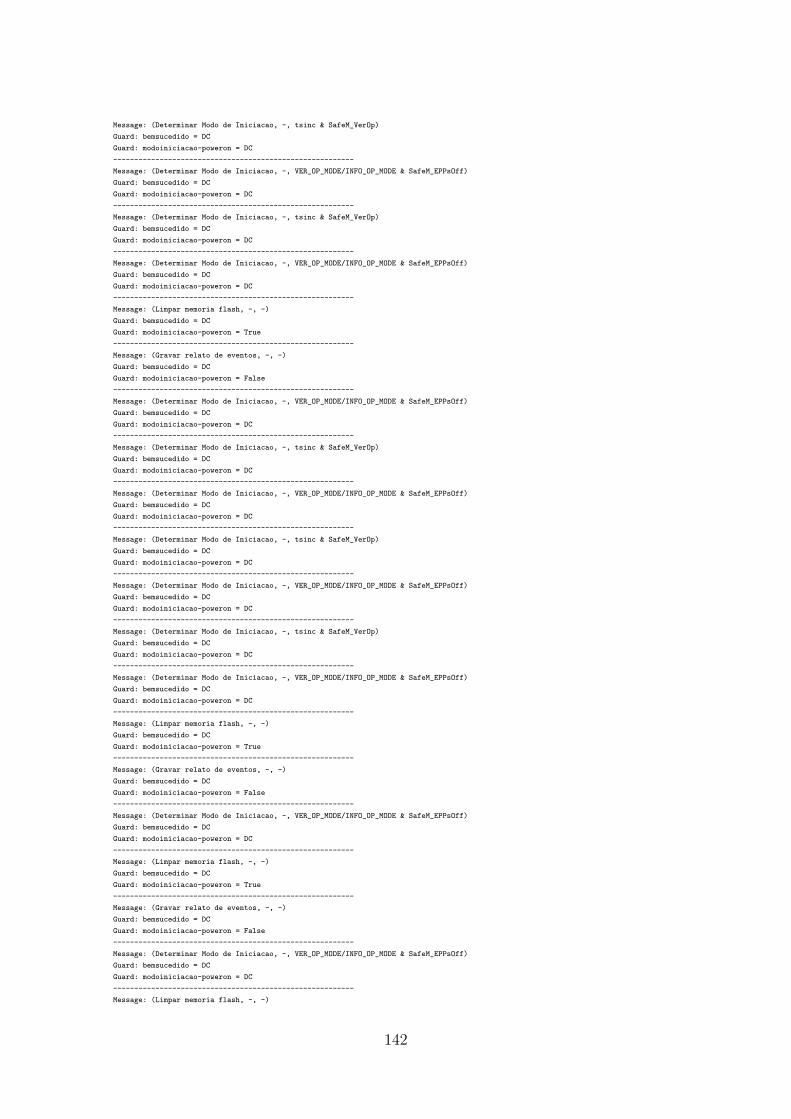
Message: (Determinar Modo de Iniciacao, -, tsinc & SafeM_VerOp)Guard: bemsucedido = DCGuard: modoiniciacao-poweron = DC---------------------------------------------------------Message: (Determinar Modo de Iniciacao, -, VER_OP_MODE/INFO_OP_MODE & SafeM_EPPsOff)Guard: bemsucedido = DCGuard: modoiniciacao-poweron = DC---------------------------------------------------------Message: (Determinar Modo de Iniciacao, -, tsinc & SafeM_VerOp)Guard: bemsucedido = DCGuard: modoiniciacao-poweron = DC---------------------------------------------------------Message: (Determinar Modo de Iniciacao, -, VER_OP_MODE/INFO_OP_MODE & SafeM_EPPsOff)Guard: bemsucedido = DCGuard: modoiniciacao-poweron = DC---------------------------------------------------------Message: (Limpar memoria flash, -, -)Guard: bemsucedido = DCGuard: modoiniciacao-poweron = True---------------------------------------------------------Message: (Gravar relato de eventos, -, -)Guard: bemsucedido = DCGuard: modoiniciacao-poweron = False---------------------------------------------------------Message: (Determinar Modo de Iniciacao, -, VER_OP_MODE/INFO_OP_MODE & SafeM_EPPsOff)Guard: bemsucedido = DCGuard: modoiniciacao-poweron = DC---------------------------------------------------------Message: (Determinar Modo de Iniciacao, -, tsinc & SafeM_VerOp)Guard: bemsucedido = DCGuard: modoiniciacao-poweron = DC---------------------------------------------------------Message: (Determinar Modo de Iniciacao, -, VER_OP_MODE/INFO_OP_MODE & SafeM_EPPsOff)Guard: bemsucedido = DCGuard: modoiniciacao-poweron = DC---------------------------------------------------------Message: (Determinar Modo de Iniciacao, -, tsinc & SafeM_VerOp)Guard: bemsucedido = DCGuard: modoiniciacao-poweron = DC---------------------------------------------------------Message: (Determinar Modo de Iniciacao, -, VER_OP_MODE/INFO_OP_MODE & SafeM_EPPsOff)Guard: bemsucedido = DCGuard: modoiniciacao-poweron = DC---------------------------------------------------------Message: (Determinar Modo de Iniciacao, -, tsinc & SafeM_VerOp)Guard: bemsucedido = DCGuard: modoiniciacao-poweron = DC---------------------------------------------------------Message: (Determinar Modo de Iniciacao, -, VER_OP_MODE/INFO_OP_MODE & SafeM_EPPsOff)Guard: bemsucedido = DCGuard: modoiniciacao-poweron = DC---------------------------------------------------------Message: (Limpar memoria flash, -, -)Guard: bemsucedido = DCGuard: modoiniciacao-poweron = True---------------------------------------------------------Message: (Gravar relato de eventos, -, -)Guard: bemsucedido = DCGuard: modoiniciacao-poweron = False---------------------------------------------------------Message: (Determinar Modo de Iniciacao, -, VER_OP_MODE/INFO_OP_MODE & SafeM_EPPsOff)Guard: bemsucedido = DCGuard: modoiniciacao-poweron = DC---------------------------------------------------------Message: (Limpar memoria flash, -, -)Guard: bemsucedido = DCGuard: modoiniciacao-poweron = True---------------------------------------------------------Message: (Gravar relato de eventos, -, -)Guard: bemsucedido = DCGuard: modoiniciacao-poweron = False---------------------------------------------------------Message: (Determinar Modo de Iniciacao, -, VER_OP_MODE/INFO_OP_MODE & SafeM_EPPsOff)Guard: bemsucedido = DCGuard: modoiniciacao-poweron = DC---------------------------------------------------------Message: (Limpar memoria flash, -, -)
142

Guard: bemsucedido = DCGuard: modoiniciacao-poweron = True---------------------------------------------------------Message: (Gravar relato de eventos, -, -)Guard: bemsucedido = DCGuard: modoiniciacao-poweron = False---------------------------------------------------------Message: (Iniciar memoria de configuracao com valores padrao, -, -)Guard: bemsucedido = DCGuard: modoiniciacao-poweron = True---------------------------------------------------------Message: (Avaliar processo de iniciacao, -, -)Guard: bemsucedido = DCGuard: modoiniciacao-poweron = False---------------------------------------------------------Message: (Limpar memoria flash, -, -)Guard: bemsucedido = DCGuard: modoiniciacao-poweron = True---------------------------------------------------------Message: (Gravar relato de eventos, -, -)Guard: bemsucedido = DCGuard: modoiniciacao-poweron = False---------------------------------------------------------Message: (Determinar Modo de Iniciacao, -, VER_OP_MODE/INFO_OP_MODE & SafeM_EPPsOff)Guard: bemsucedido = DCGuard: modoiniciacao-poweron = DC---------------------------------------------------------Message: (Limpar memoria flash, -, -)Guard: bemsucedido = DCGuard: modoiniciacao-poweron = True---------------------------------------------------------Message: (Gravar relato de eventos, -, -)Guard: bemsucedido = DCGuard: modoiniciacao-poweron = False---------------------------------------------------------Message: (Determinar Modo de Iniciacao, -, VER_OP_MODE/INFO_OP_MODE & SafeM_EPPsOff)Guard: bemsucedido = DCGuard: modoiniciacao-poweron = DC---------------------------------------------------------Message: (Limpar memoria flash, -, -)Guard: bemsucedido = DCGuard: modoiniciacao-poweron = True---------------------------------------------------------Message: (Gravar relato de eventos, -, -)Guard: bemsucedido = DCGuard: modoiniciacao-poweron = False---------------------------------------------------------Message: (Determinar Modo de Iniciacao, -, VER_OP_MODE/INFO_OP_MODE & SafeM_EPPsOff)Guard: bemsucedido = DCGuard: modoiniciacao-poweron = DC---------------------------------------------------------Message: (Limpar memoria flash, -, -)Guard: bemsucedido = DCGuard: modoiniciacao-poweron = True---------------------------------------------------------Message: (Gravar relato de eventos, -, -)Guard: bemsucedido = DCGuard: modoiniciacao-poweron = False---------------------------------------------------------Message: (Iniciar memoria de configuracao com valores padrao, -, -)Guard: bemsucedido = DCGuard: modoiniciacao-poweron = True---------------------------------------------------------Message: (Avaliar processo de iniciacao, -, -)Guard: bemsucedido = DCGuard: modoiniciacao-poweron = False---------------------------------------------------------Message: (Limpar memoria flash, -, -)Guard: bemsucedido = DCGuard: modoiniciacao-poweron = True---------------------------------------------------------Message: (Gravar relato de eventos, -, -)Guard: bemsucedido = DCGuard: modoiniciacao-poweron = False---------------------------------------------------------Message: (Iniciar memoria de configuracao com valores padrao, -, -)Guard: bemsucedido = DC
143

Guard: modoiniciacao-poweron = True---------------------------------------------------------Message: (Avaliar processo de iniciacao, -, -)Guard: bemsucedido = DCGuard: modoiniciacao-poweron = False---------------------------------------------------------Message: (Limpar memoria flash, -, -)Guard: bemsucedido = DCGuard: modoiniciacao-poweron = True---------------------------------------------------------Message: (Gravar relato de eventos, -, -)Guard: bemsucedido = DCGuard: modoiniciacao-poweron = False---------------------------------------------------------Message: (Iniciar memoria de configuracao com valores padrao, -, -)Guard: bemsucedido = DCGuard: modoiniciacao-poweron = True---------------------------------------------------------Message: (Avaliar processo de iniciacao, -, -)Guard: bemsucedido = DCGuard: modoiniciacao-poweron = False---------------------------------------------------------Message: (Gravar relato de eventos, -, -)Guard: bemsucedido = DCGuard: modoiniciacao-poweron = True---------------------------------------------------------Message: (Re-configurar, -, -)Guard: bemsucedido = TrueGuard: modoiniciacao-poweron = False---------------------------------------------------------Message: (Voltar ao Inicio, -, -)Guard: bemsucedido = FalseGuard: modoiniciacao-poweron = False---------------------------------------------------------Message: (Iniciar memoria de configuracao com valores padrao, -, -)Guard: bemsucedido = DCGuard: modoiniciacao-poweron = True---------------------------------------------------------Message: (Avaliar processo de iniciacao, -, -)Guard: bemsucedido = DCGuard: modoiniciacao-poweron = False---------------------------------------------------------Message: (Limpar memoria flash, -, -)Guard: bemsucedido = DCGuard: modoiniciacao-poweron = True---------------------------------------------------------Message: (Gravar relato de eventos, -, -)Guard: bemsucedido = DCGuard: modoiniciacao-poweron = False---------------------------------------------------------Message: (Iniciar memoria de configuracao com valores padrao, -, -)Guard: bemsucedido = DCGuard: modoiniciacao-poweron = True---------------------------------------------------------Message: (Avaliar processo de iniciacao, -, -)Guard: bemsucedido = DCGuard: modoiniciacao-poweron = False---------------------------------------------------------Message: (Limpar memoria flash, -, -)Guard: bemsucedido = DCGuard: modoiniciacao-poweron = True---------------------------------------------------------Message: (Gravar relato de eventos, -, -)Guard: bemsucedido = DCGuard: modoiniciacao-poweron = False---------------------------------------------------------Message: (Iniciar memoria de configuracao com valores padrao, -, -)Guard: bemsucedido = DCGuard: modoiniciacao-poweron = True---------------------------------------------------------Message: (Avaliar processo de iniciacao, -, -)Guard: bemsucedido = DCGuard: modoiniciacao-poweron = False---------------------------------------------------------Message: (Limpar memoria flash, -, -)Guard: bemsucedido = DCGuard: modoiniciacao-poweron = True
144

---------------------------------------------------------Message: (Gravar relato de eventos, -, -)Guard: bemsucedido = DCGuard: modoiniciacao-poweron = False---------------------------------------------------------Message: (Iniciar memoria de configuracao com valores padrao, -, -)Guard: bemsucedido = DCGuard: modoiniciacao-poweron = True---------------------------------------------------------Message: (Avaliar processo de iniciacao, -, -)Guard: bemsucedido = DCGuard: modoiniciacao-poweron = False---------------------------------------------------------Message: (Gravar relato de eventos, -, -)Guard: bemsucedido = DCGuard: modoiniciacao-poweron = True---------------------------------------------------------Message: (Re-configurar, -, -)Guard: bemsucedido = TrueGuard: modoiniciacao-poweron = False---------------------------------------------------------Message: (Voltar ao Inicio, -, -)Guard: bemsucedido = FalseGuard: modoiniciacao-poweron = False---------------------------------------------------------Message: (Iniciar memoria de configuracao com valores padrao, -, -)Guard: bemsucedido = DCGuard: modoiniciacao-poweron = True---------------------------------------------------------Message: (Avaliar processo de iniciacao, -, -)Guard: bemsucedido = DCGuard: modoiniciacao-poweron = False---------------------------------------------------------Message: (Gravar relato de eventos, -, -)Guard: bemsucedido = DCGuard: modoiniciacao-poweron = True---------------------------------------------------------Message: (Re-configurar, -, -)Guard: bemsucedido = TrueGuard: modoiniciacao-poweron = False---------------------------------------------------------Message: (Voltar ao Inicio, -, -)Guard: bemsucedido = FalseGuard: modoiniciacao-poweron = False---------------------------------------------------------Message: (Iniciar memoria de configuracao com valores padrao, -, -)Guard: bemsucedido = DCGuard: modoiniciacao-poweron = True---------------------------------------------------------Message: (Avaliar processo de iniciacao, -, -)Guard: bemsucedido = DCGuard: modoiniciacao-poweron = False---------------------------------------------------------Message: (Gravar relato de eventos, -, -)Guard: bemsucedido = DCGuard: modoiniciacao-poweron = True---------------------------------------------------------Message: (Re-configurar, -, -)Guard: bemsucedido = TrueGuard: modoiniciacao-poweron = False---------------------------------------------------------Message: (Voltar ao Inicio, -, -)Guard: bemsucedido = FalseGuard: modoiniciacao-poweron = False---------------------------------------------------------Message: (Avaliar processo de iniciacao, -, -)Guard: bemsucedido = DCGuard: modoiniciacao-poweron = True---------------------------------------------------------Message: (Mudar para modo de operacao SEGURANCA, -, -)Guard: bemsucedido = TrueGuard: modoiniciacao-poweron = False---------------------------------------------------------Message: (Gravar relato de eventos, -, -)Guard: bemsucedido = DCGuard: modoiniciacao-poweron = True---------------------------------------------------------
145

Message: (Re-configurar, -, -)Guard: bemsucedido = TrueGuard: modoiniciacao-poweron = False---------------------------------------------------------Message: (Voltar ao Inicio, -, -)Guard: bemsucedido = FalseGuard: modoiniciacao-poweron = False---------------------------------------------------------Message: (Iniciar memoria de configuracao com valores padrao, -, -)Guard: bemsucedido = DCGuard: modoiniciacao-poweron = True---------------------------------------------------------Message: (Avaliar processo de iniciacao, -, -)Guard: bemsucedido = DCGuard: modoiniciacao-poweron = False---------------------------------------------------------Message: (Gravar relato de eventos, -, -)Guard: bemsucedido = DCGuard: modoiniciacao-poweron = True---------------------------------------------------------Message: (Re-configurar, -, -)Guard: bemsucedido = TrueGuard: modoiniciacao-poweron = False---------------------------------------------------------Message: (Voltar ao Inicio, -, -)Guard: bemsucedido = FalseGuard: modoiniciacao-poweron = False---------------------------------------------------------Message: (Iniciar memoria de configuracao com valores padrao, -, -)Guard: bemsucedido = DCGuard: modoiniciacao-poweron = True---------------------------------------------------------Message: (Avaliar processo de iniciacao, -, -)Guard: bemsucedido = DCGuard: modoiniciacao-poweron = False---------------------------------------------------------Message: (Gravar relato de eventos, -, -)Guard: bemsucedido = DCGuard: modoiniciacao-poweron = True---------------------------------------------------------Message: (Re-configurar, -, -)Guard: bemsucedido = TrueGuard: modoiniciacao-poweron = False---------------------------------------------------------Message: (Voltar ao Inicio, -, -)Guard: bemsucedido = FalseGuard: modoiniciacao-poweron = False---------------------------------------------------------Message: (Iniciar memoria de configuracao com valores padrao, -, -)Guard: bemsucedido = DCGuard: modoiniciacao-poweron = True---------------------------------------------------------Message: (Avaliar processo de iniciacao, -, -)Guard: bemsucedido = DCGuard: modoiniciacao-poweron = False---------------------------------------------------------Message: (Gravar relato de eventos, -, -)Guard: bemsucedido = DCGuard: modoiniciacao-poweron = True---------------------------------------------------------Message: (Re-configurar, -, -)Guard: bemsucedido = TrueGuard: modoiniciacao-poweron = False---------------------------------------------------------Message: (Voltar ao Inicio, -, -)Guard: bemsucedido = FalseGuard: modoiniciacao-poweron = False---------------------------------------------------------Message: (Avaliar processo de iniciacao, -, -)Guard: bemsucedido = DCGuard: modoiniciacao-poweron = True---------------------------------------------------------Message: (Mudar para modo de operacao SEGURANCA, -, -)Guard: bemsucedido = TrueGuard: modoiniciacao-poweron = False---------------------------------------------------------Message: (Gravar relato de eventos, -, -)
146

Guard: bemsucedido = DCGuard: modoiniciacao-poweron = True---------------------------------------------------------Message: (Re-configurar, -, -)Guard: bemsucedido = TrueGuard: modoiniciacao-poweron = False---------------------------------------------------------Message: (Voltar ao Inicio, -, -)Guard: bemsucedido = FalseGuard: modoiniciacao-poweron = False---------------------------------------------------------Message: (Avaliar processo de iniciacao, -, -)Guard: bemsucedido = DCGuard: modoiniciacao-poweron = True---------------------------------------------------------Message: (Mudar para modo de operacao SEGURANCA, -, -)Guard: bemsucedido = TrueGuard: modoiniciacao-poweron = False---------------------------------------------------------Message: (Gravar relato de eventos, -, -)Guard: bemsucedido = DCGuard: modoiniciacao-poweron = True---------------------------------------------------------Message: (Re-configurar, -, -)Guard: bemsucedido = TrueGuard: modoiniciacao-poweron = False---------------------------------------------------------Message: (Voltar ao Inicio, -, -)Guard: bemsucedido = FalseGuard: modoiniciacao-poweron = False---------------------------------------------------------Message: (Avaliar processo de iniciacao, -, -)Guard: bemsucedido = DCGuard: modoiniciacao-poweron = True---------------------------------------------------------Message: (Mudar para modo de operacao SEGURANCA, -, -)Guard: bemsucedido = TrueGuard: modoiniciacao-poweron = False---------------------------------------------------------Message: (Re-configurar, -, -)Guard: bemsucedido = TrueGuard: modoiniciacao-poweron = True---------------------------------------------------------Message: (Voltar ao Inicio, -, -)Guard: bemsucedido = FalseGuard: modoiniciacao-poweron = True---------------------------------------------------------Message: (Avaliar processo de iniciacao, -, -)Guard: bemsucedido = DCGuard: modoiniciacao-poweron = True---------------------------------------------------------Message: (Mudar para modo de operacao SEGURANCA, -, -)Guard: bemsucedido = TrueGuard: modoiniciacao-poweron = False---------------------------------------------------------Message: (Gravar relato de eventos, -, -)Guard: bemsucedido = DCGuard: modoiniciacao-poweron = True---------------------------------------------------------Message: (Re-configurar, -, -)Guard: bemsucedido = TrueGuard: modoiniciacao-poweron = False---------------------------------------------------------Message: (Voltar ao Inicio, -, -)Guard: bemsucedido = FalseGuard: modoiniciacao-poweron = False---------------------------------------------------------Message: (Avaliar processo de iniciacao, -, -)Guard: bemsucedido = DCGuard: modoiniciacao-poweron = True---------------------------------------------------------Message: (Mudar para modo de operacao SEGURANCA, -, -)Guard: bemsucedido = TrueGuard: modoiniciacao-poweron = False---------------------------------------------------------Message: (Gravar relato de eventos, -, -)Guard: bemsucedido = DC
147

Guard: modoiniciacao-poweron = True---------------------------------------------------------Message: (Re-configurar, -, -)Guard: bemsucedido = TrueGuard: modoiniciacao-poweron = False---------------------------------------------------------Message: (Voltar ao Inicio, -, -)Guard: bemsucedido = FalseGuard: modoiniciacao-poweron = False---------------------------------------------------------Message: (Avaliar processo de iniciacao, -, -)Guard: bemsucedido = DCGuard: modoiniciacao-poweron = True---------------------------------------------------------Message: (Mudar para modo de operacao SEGURANCA, -, -)Guard: bemsucedido = TrueGuard: modoiniciacao-poweron = False---------------------------------------------------------Message: (Gravar relato de eventos, -, -)Guard: bemsucedido = DCGuard: modoiniciacao-poweron = True---------------------------------------------------------Message: (Re-configurar, -, -)Guard: bemsucedido = TrueGuard: modoiniciacao-poweron = False---------------------------------------------------------Message: (Voltar ao Inicio, -, -)Guard: bemsucedido = FalseGuard: modoiniciacao-poweron = False---------------------------------------------------------Message: (Avaliar processo de iniciacao, -, -)Guard: bemsucedido = DCGuard: modoiniciacao-poweron = True---------------------------------------------------------Message: (Mudar para modo de operacao SEGURANCA, -, -)Guard: bemsucedido = TrueGuard: modoiniciacao-poweron = False---------------------------------------------------------Message: (Re-configurar, -, -)Guard: bemsucedido = TrueGuard: modoiniciacao-poweron = True---------------------------------------------------------Message: (Voltar ao Inicio, -, -)Guard: bemsucedido = FalseGuard: modoiniciacao-poweron = True---------------------------------------------------------Message: (Avaliar processo de iniciacao, -, -)Guard: bemsucedido = DCGuard: modoiniciacao-poweron = True---------------------------------------------------------Message: (Mudar para modo de operacao SEGURANCA, -, -)Guard: bemsucedido = TrueGuard: modoiniciacao-poweron = False---------------------------------------------------------Message: (Re-configurar, -, -)Guard: bemsucedido = TrueGuard: modoiniciacao-poweron = True---------------------------------------------------------Message: (Voltar ao Inicio, -, -)Guard: bemsucedido = FalseGuard: modoiniciacao-poweron = True---------------------------------------------------------Message: (Avaliar processo de iniciacao, -, -)Guard: bemsucedido = DCGuard: modoiniciacao-poweron = True---------------------------------------------------------Message: (Mudar para modo de operacao SEGURANCA, -, -)Guard: bemsucedido = TrueGuard: modoiniciacao-poweron = False---------------------------------------------------------Message: (Re-configurar, -, -)Guard: bemsucedido = TrueGuard: modoiniciacao-poweron = True---------------------------------------------------------Message: (Voltar ao Inicio, -, -)Guard: bemsucedido = FalseGuard: modoiniciacao-poweron = True
148

---------------------------------------------------------Message: (Mudar para modo de operacao SEGURANCA, -, -)Guard: bemsucedido = TrueGuard: modoiniciacao-poweron = True---------------------------------------------------------Message: (Re-configurar, -, -)Guard: bemsucedido = TrueGuard: modoiniciacao-poweron = True---------------------------------------------------------Message: (Voltar ao Inicio, -, -)Guard: bemsucedido = FalseGuard: modoiniciacao-poweron = True---------------------------------------------------------Message: (Avaliar processo de iniciacao, -, -)Guard: bemsucedido = DCGuard: modoiniciacao-poweron = True---------------------------------------------------------Message: (Mudar para modo de operacao SEGURANCA, -, -)Guard: bemsucedido = TrueGuard: modoiniciacao-poweron = False---------------------------------------------------------Message: (Re-configurar, -, -)Guard: bemsucedido = TrueGuard: modoiniciacao-poweron = True---------------------------------------------------------Message: (Voltar ao Inicio, -, -)Guard: bemsucedido = FalseGuard: modoiniciacao-poweron = True---------------------------------------------------------Message: (Avaliar processo de iniciacao, -, -)Guard: bemsucedido = DCGuard: modoiniciacao-poweron = True---------------------------------------------------------Message: (Mudar para modo de operacao SEGURANCA, -, -)Guard: bemsucedido = TrueGuard: modoiniciacao-poweron = False---------------------------------------------------------Message: (Re-configurar, -, -)Guard: bemsucedido = TrueGuard: modoiniciacao-poweron = True---------------------------------------------------------Message: (Voltar ao Inicio, -, -)Guard: bemsucedido = FalseGuard: modoiniciacao-poweron = True---------------------------------------------------------Message: (Avaliar processo de iniciacao, -, -)Guard: bemsucedido = DCGuard: modoiniciacao-poweron = True---------------------------------------------------------Message: (Mudar para modo de operacao SEGURANCA, -, -)Guard: bemsucedido = TrueGuard: modoiniciacao-poweron = False---------------------------------------------------------Message: (Re-configurar, -, -)Guard: bemsucedido = TrueGuard: modoiniciacao-poweron = True---------------------------------------------------------Message: (Voltar ao Inicio, -, -)Guard: bemsucedido = FalseGuard: modoiniciacao-poweron = True---------------------------------------------------------Message: (Mudar para modo de operacao SEGURANCA, -, -)Guard: bemsucedido = TrueGuard: modoiniciacao-poweron = True---------------------------------------------------------Message: (Re-configurar, -, -)Guard: bemsucedido = TrueGuard: modoiniciacao-poweron = True---------------------------------------------------------Message: (Voltar ao Inicio, -, -)Guard: bemsucedido = FalseGuard: modoiniciacao-poweron = True---------------------------------------------------------Message: (Mudar para modo de operacao SEGURANCA, -, -)Guard: bemsucedido = TrueGuard: modoiniciacao-poweron = True---------------------------------------------------------
149

Message: (Re-configurar, -, -)Guard: bemsucedido = TrueGuard: modoiniciacao-poweron = True---------------------------------------------------------Message: (Voltar ao Inicio, -, -)Guard: bemsucedido = FalseGuard: modoiniciacao-poweron = True---------------------------------------------------------Message: (Mudar para modo de operacao SEGURANCA, -, -)Guard: bemsucedido = TrueGuard: modoiniciacao-poweron = True---------------------------------------------------------Message: (Mudar para modo de operacao SEGURANCA, -, -)Guard: bemsucedido = TrueGuard: modoiniciacao-poweron = True---------------------------------------------------------Message: (Re-configurar, -, -)Guard: bemsucedido = TrueGuard: modoiniciacao-poweron = True---------------------------------------------------------Message: (Voltar ao Inicio, -, -)Guard: bemsucedido = FalseGuard: modoiniciacao-poweron = True---------------------------------------------------------Message: (Mudar para modo de operacao SEGURANCA, -, -)Guard: bemsucedido = TrueGuard: modoiniciacao-poweron = True---------------------------------------------------------Message: (Re-configurar, -, -)Guard: bemsucedido = TrueGuard: modoiniciacao-poweron = True---------------------------------------------------------Message: (Voltar ao Inicio, -, -)Guard: bemsucedido = FalseGuard: modoiniciacao-poweron = True---------------------------------------------------------Message: (Mudar para modo de operacao SEGURANCA, -, -)Guard: bemsucedido = TrueGuard: modoiniciacao-poweron = True---------------------------------------------------------Message: (Re-configurar, -, -)Guard: bemsucedido = TrueGuard: modoiniciacao-poweron = True---------------------------------------------------------Message: (Voltar ao Inicio, -, -)Guard: bemsucedido = FalseGuard: modoiniciacao-poweron = True---------------------------------------------------------Message: (Mudar para modo de operacao SEGURANCA, -, -)Guard: bemsucedido = TrueGuard: modoiniciacao-poweron = True---------------------------------------------------------Message: (Mudar para modo de operacao SEGURANCA, -, -)Guard: bemsucedido = TrueGuard: modoiniciacao-poweron = True---------------------------------------------------------Message: (Mudar para modo de operacao SEGURANCA, -, -)Guard: bemsucedido = TrueGuard: modoiniciacao-poweron = True---------------------------------------------------------Message: (Mudar para modo de operacao SEGURANCA, -, -)Guard: bemsucedido = TrueGuard: modoiniciacao-poweron = True---------------------------------------------------------Message: (Mudar para modo de operacao SEGURANCA, -, -)Guard: bemsucedido = TrueGuard: modoiniciacao-poweron = True---------------------------------------------------------Message: (Mudar para modo de operacao SEGURANCA, -, -)Guard: bemsucedido = TrueGuard: modoiniciacao-poweron = True---------------------------------------------------------NUMBER OF STATES: 243
150
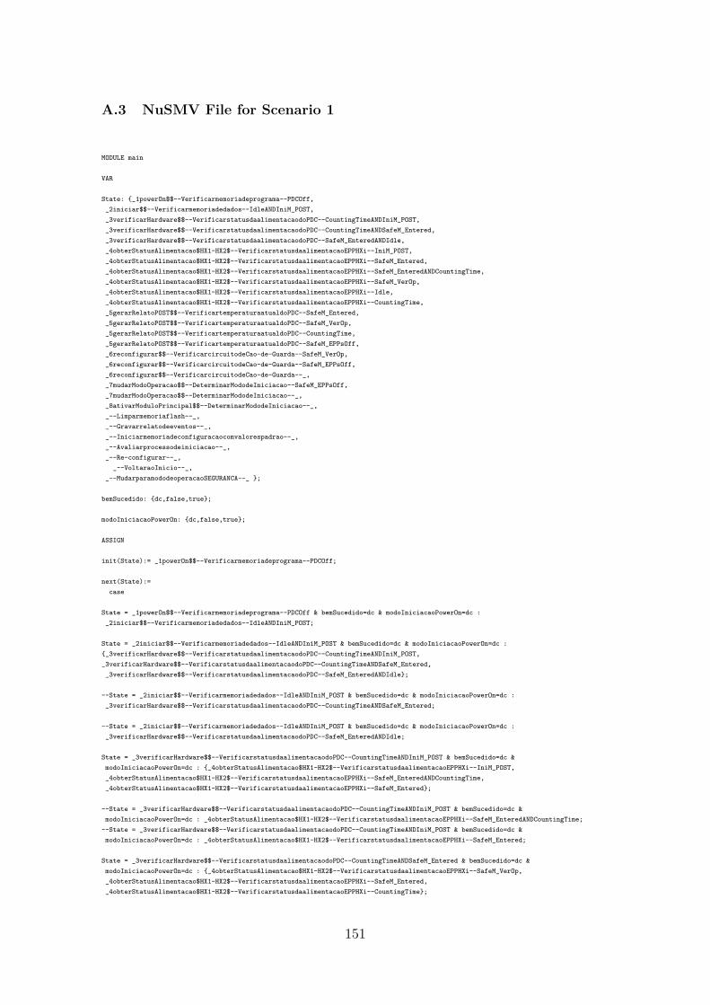
A.3 NuSMV File for Scenario 1
MODULE main
VAR
State: {_1powerOn$$--Verificarmemoriadeprograma--PDCOff,_2iniciar$$--Verificarmemoriadedados--IdleANDIniM_POST,_3verificarHardware$$--VerificarstatusdaalimentacaodoPDC--CountingTimeANDIniM_POST,_3verificarHardware$$--VerificarstatusdaalimentacaodoPDC--CountingTimeANDSafeM_Entered,_3verificarHardware$$--VerificarstatusdaalimentacaodoPDC--SafeM_EnteredANDIdle,_4obterStatusAlimentacao$HX1-HX2$--VerificarstatusdaalimentacaoEPPHXi--IniM_POST,_4obterStatusAlimentacao$HX1-HX2$--VerificarstatusdaalimentacaoEPPHXi--SafeM_Entered,_4obterStatusAlimentacao$HX1-HX2$--VerificarstatusdaalimentacaoEPPHXi--SafeM_EnteredANDCountingTime,_4obterStatusAlimentacao$HX1-HX2$--VerificarstatusdaalimentacaoEPPHXi--SafeM_VerOp,_4obterStatusAlimentacao$HX1-HX2$--VerificarstatusdaalimentacaoEPPHXi--Idle,_4obterStatusAlimentacao$HX1-HX2$--VerificarstatusdaalimentacaoEPPHXi--CountingTime,_5gerarRelatoPOST$$--VerificartemperaturaatualdoPDC--SafeM_Entered,_5gerarRelatoPOST$$--VerificartemperaturaatualdoPDC--SafeM_VerOp,_5gerarRelatoPOST$$--VerificartemperaturaatualdoPDC--CountingTime,_5gerarRelatoPOST$$--VerificartemperaturaatualdoPDC--SafeM_EPPsOff,_6reconfigurar$$--VerificarcircuitodeCao-de-Guarda--SafeM_VerOp,_6reconfigurar$$--VerificarcircuitodeCao-de-Guarda--SafeM_EPPsOff,_6reconfigurar$$--VerificarcircuitodeCao-de-Guarda--_,_7mudarModoOperacao$$--DeterminarMododeIniciacao--SafeM_EPPsOff,_7mudarModoOperacao$$--DeterminarMododeIniciacao--_,_8ativarModuloPrincipal$$--DeterminarMododeIniciacao--_,_--Limparmemoriaflash--_,_--Gravarrelatodeeventos--_,_--Iniciarmemoriadeconfiguracaocomvalorespadrao--_,_--Avaliarprocessodeiniciacao--_,_--Re-configurar--_,
_--VoltaraoInicio--_,_--MudarparamododeoperacaoSEGURANCA--_ };
bemSucedido: {dc,false,true};
modoIniciacaoPowerOn: {dc,false,true};
ASSIGN
init(State):= _1powerOn$$--Verificarmemoriadeprograma--PDCOff;
next(State):=case
State = _1powerOn$$--Verificarmemoriadeprograma--PDCOff & bemSucedido=dc & modoIniciacaoPowerOn=dc :_2iniciar$$--Verificarmemoriadedados--IdleANDIniM_POST;
State = _2iniciar$$--Verificarmemoriadedados--IdleANDIniM_POST & bemSucedido=dc & modoIniciacaoPowerOn=dc :{_3verificarHardware$$--VerificarstatusdaalimentacaodoPDC--CountingTimeANDIniM_POST,_3verificarHardware$$--VerificarstatusdaalimentacaodoPDC--CountingTimeANDSafeM_Entered,_3verificarHardware$$--VerificarstatusdaalimentacaodoPDC--SafeM_EnteredANDIdle};
--State = _2iniciar$$--Verificarmemoriadedados--IdleANDIniM_POST & bemSucedido=dc & modoIniciacaoPowerOn=dc :_3verificarHardware$$--VerificarstatusdaalimentacaodoPDC--CountingTimeANDSafeM_Entered;
--State = _2iniciar$$--Verificarmemoriadedados--IdleANDIniM_POST & bemSucedido=dc & modoIniciacaoPowerOn=dc :_3verificarHardware$$--VerificarstatusdaalimentacaodoPDC--SafeM_EnteredANDIdle;
State = _3verificarHardware$$--VerificarstatusdaalimentacaodoPDC--CountingTimeANDIniM_POST & bemSucedido=dc &modoIniciacaoPowerOn=dc : {_4obterStatusAlimentacao$HX1-HX2$--VerificarstatusdaalimentacaoEPPHXi--IniM_POST,_4obterStatusAlimentacao$HX1-HX2$--VerificarstatusdaalimentacaoEPPHXi--SafeM_EnteredANDCountingTime,_4obterStatusAlimentacao$HX1-HX2$--VerificarstatusdaalimentacaoEPPHXi--SafeM_Entered};
--State = _3verificarHardware$$--VerificarstatusdaalimentacaodoPDC--CountingTimeANDIniM_POST & bemSucedido=dc &modoIniciacaoPowerOn=dc : _4obterStatusAlimentacao$HX1-HX2$--VerificarstatusdaalimentacaoEPPHXi--SafeM_EnteredANDCountingTime;
--State = _3verificarHardware$$--VerificarstatusdaalimentacaodoPDC--CountingTimeANDIniM_POST & bemSucedido=dc &modoIniciacaoPowerOn=dc : _4obterStatusAlimentacao$HX1-HX2$--VerificarstatusdaalimentacaoEPPHXi--SafeM_Entered;
State = _3verificarHardware$$--VerificarstatusdaalimentacaodoPDC--CountingTimeANDSafeM_Entered & bemSucedido=dc &modoIniciacaoPowerOn=dc : {_4obterStatusAlimentacao$HX1-HX2$--VerificarstatusdaalimentacaoEPPHXi--SafeM_VerOp,_4obterStatusAlimentacao$HX1-HX2$--VerificarstatusdaalimentacaoEPPHXi--SafeM_Entered,_4obterStatusAlimentacao$HX1-HX2$--VerificarstatusdaalimentacaoEPPHXi--CountingTime};
151

--State = _3verificarHardware$$--VerificarstatusdaalimentacaodoPDC--CountingTimeANDSafeM_Entered & bemSucedido=dc &modoIniciacaoPowerOn=dc : _4obterStatusAlimentacao$HX1-HX2$--VerificarstatusdaalimentacaoEPPHXi--SafeM_Entered;
--State = _3verificarHardware$$--VerificarstatusdaalimentacaodoPDC--CountingTimeANDSafeM_Entered & bemSucedido=dc &modoIniciacaoPowerOn=dc : _4obterStatusAlimentacao$HX1-HX2$--VerificarstatusdaalimentacaoEPPHXi--CountingTime;
State = _3verificarHardware$$--VerificarstatusdaalimentacaodoPDC--SafeM_EnteredANDIdle & bemSucedido=dc & modoIniciacaoPowerOn=dc :{_4obterStatusAlimentacao$HX1-HX2$--VerificarstatusdaalimentacaoEPPHXi--Idle,_4obterStatusAlimentacao$HX1-HX2$--VerificarstatusdaalimentacaoEPPHXi--CountingTime,_4obterStatusAlimentacao$HX1-HX2$--VerificarstatusdaalimentacaoEPPHXi--SafeM_EnteredANDCountingTime};
--State = _3verificarHardware$$--VerificarstatusdaalimentacaodoPDC--SafeM_EnteredANDIdle & bemSucedido=dc & modoIniciacaoPowerOn=dc: _4obterStatusAlimentacao$HX1-HX2$--VerificarstatusdaalimentacaoEPPHXi--CountingTime;
--State = _3verificarHardware$$--VerificarstatusdaalimentacaodoPDC--SafeM_EnteredANDIdle & bemSucedido=dc & modoIniciacaoPowerOn=dc: _4obterStatusAlimentacao$HX1-HX2$--VerificarstatusdaalimentacaoEPPHXi--SafeM_EnteredANDCountingTime;
State = _4obterStatusAlimentacao$HX1-HX2$--VerificarstatusdaalimentacaoEPPHXi--IniM_POST & bemSucedido=dc & modoIniciacaoPowerOn=dc: _5gerarRelatoPOST$$--VerificartemperaturaatualdoPDC--SafeM_Entered;
State = _4obterStatusAlimentacao$HX1-HX2$--VerificarstatusdaalimentacaoEPPHXi--SafeM_EnteredANDCountingTime & bemSucedido=dc &modoIniciacaoPowerOn=dc : {_5gerarRelatoPOST$$--VerificartemperaturaatualdoPDC--SafeM_Entered,_5gerarRelatoPOST$$--VerificartemperaturaatualdoPDC--SafeM_VerOp,_5gerarRelatoPOST$$--VerificartemperaturaatualdoPDC--CountingTime};
--State = _4obterStatusAlimentacao$HX1-HX2$--VerificarstatusdaalimentacaoEPPHXi--SafeM_EnteredANDCountingTime & bemSucedido=dc &modoIniciacaoPowerOn=dc : _5gerarRelatoPOST$$--VerificartemperaturaatualdoPDC--SafeM_VerOp;
--State = _4obterStatusAlimentacao$HX1-HX2$--VerificarstatusdaalimentacaoEPPHXi--SafeM_EnteredANDCountingTime & bemSucedido=dc &modoIniciacaoPowerOn=dc : _5gerarRelatoPOST$$--VerificartemperaturaatualdoPDC--CountingTime;
State = _4obterStatusAlimentacao$HX1-HX2$--VerificarstatusdaalimentacaoEPPHXi--SafeM_Entered & bemSucedido=dc &modoIniciacaoPowerOn=dc : _5gerarRelatoPOST$$--VerificartemperaturaatualdoPDC--SafeM_VerOp;
State = _4obterStatusAlimentacao$HX1-HX2$--VerificarstatusdaalimentacaoEPPHXi--SafeM_VerOp & bemSucedido=dc &modoIniciacaoPowerOn=dc : _5gerarRelatoPOST$$--VerificartemperaturaatualdoPDC--SafeM_EPPsOff;
State = _4obterStatusAlimentacao$HX1-HX2$--VerificarstatusdaalimentacaoEPPHXi--CountingTime & bemSucedido=dc &modoIniciacaoPowerOn=dc : _5gerarRelatoPOST$$--VerificartemperaturaatualdoPDC--SafeM_VerOp;
State = _4obterStatusAlimentacao$HX1-HX2$--VerificarstatusdaalimentacaoEPPHXi--Idle & bemSucedido=dc & modoIniciacaoPowerOn=dc :_5gerarRelatoPOST$$--VerificartemperaturaatualdoPDC--CountingTime;
State = _5gerarRelatoPOST$$--VerificartemperaturaatualdoPDC--SafeM_Entered & bemSucedido=dc & modoIniciacaoPowerOn=dc :_6reconfigurar$$--VerificarcircuitodeCao-de-Guarda--SafeM_VerOp;
State = _5gerarRelatoPOST$$--VerificartemperaturaatualdoPDC--SafeM_VerOp & bemSucedido=dc & modoIniciacaoPowerOn=dc :_6reconfigurar$$--VerificarcircuitodeCao-de-Guarda--SafeM_EPPsOff;
State = _5gerarRelatoPOST$$--VerificartemperaturaatualdoPDC--CountingTime & bemSucedido=dc & modoIniciacaoPowerOn=dc :_6reconfigurar$$--VerificarcircuitodeCao-de-Guarda--SafeM_VerOp;
State = _5gerarRelatoPOST$$--VerificartemperaturaatualdoPDC--SafeM_EPPsOff & bemSucedido=dc & modoIniciacaoPowerOn=dc :_6reconfigurar$$--VerificarcircuitodeCao-de-Guarda--_;
State = _6reconfigurar$$--VerificarcircuitodeCao-de-Guarda--SafeM_EPPsOff & bemSucedido=dc & modoIniciacaoPowerOn=dc :_7mudarModoOperacao$$--DeterminarMododeIniciacao--_;
State = _6reconfigurar$$--VerificarcircuitodeCao-de-Guarda--SafeM_VerOp & bemSucedido=dc & modoIniciacaoPowerOn=dc :_7mudarModoOperacao$$--DeterminarMododeIniciacao--SafeM_EPPsOff;
State = _6reconfigurar$$--VerificarcircuitodeCao-de-Guarda--_ & bemSucedido=dc & modoIniciacaoPowerOn=dc :_7mudarModoOperacao$$--DeterminarMododeIniciacao--_;
State = _7mudarModoOperacao$$--DeterminarMododeIniciacao--SafeM_EPPsOff & bemSucedido=dc & modoIniciacaoPowerOn=dc :_8ativarModuloPrincipal$$--DeterminarMododeIniciacao--_;
State = _7mudarModoOperacao$$--DeterminarMododeIniciacao--_ & bemSucedido=dc & modoIniciacaoPowerOn=dc :_8ativarModuloPrincipal$$--DeterminarMododeIniciacao--_;
State = _8ativarModuloPrincipal$$--DeterminarMododeIniciacao--_ & bemSucedido=dc & modoIniciacaoPowerOn=true :_--Limparmemoriaflash--_;
State = _8ativarModuloPrincipal$$--DeterminarMododeIniciacao--_ & bemSucedido=dc & modoIniciacaoPowerOn=false :_--Gravarrelatodeeventos--_;
152

State = _--Limparmemoriaflash--_ & bemSucedido=dc & modoIniciacaoPowerOn=true : _--Iniciarmemoriadeconfiguracaocomvalorespadrao--_;
State = _--Gravarrelatodeeventos--_ & bemSucedido=dc & modoIniciacaoPowerOn=false : _--Avaliarprocessodeiniciacao--_;
State = _--Iniciarmemoriadeconfiguracaocomvalorespadrao--_ & bemSucedido=dc & modoIniciacaoPowerOn=true_--Gravarrelatodeeventos--_;
State = _--Avaliarprocessodeiniciacao--_ & bemSucedido=true & modoIniciacaoPowerOn=false : _--Re-configurar--_;
State = _--Avaliarprocessodeiniciacao--_ & bemSucedido=false & modoIniciacaoPowerOn=false : _--VoltaraoInicio--_;
State = _--Gravarrelatodeeventos--_ & bemSucedido=dc & modoIniciacaoPowerOn=true : _--Avaliarprocessodeiniciacao--_;
State = _--Re-configurar--_ & bemSucedido=true & modoIniciacaoPowerOn=false : _--MudarparamododeoperacaoSEGURANCA--_;
State = _--Avaliarprocessodeiniciacao--_ & bemSucedido=true & modoIniciacaoPowerOn=true : _--Re-configurar--_;
State = _--Avaliarprocessodeiniciacao--_ & bemSucedido=false & modoIniciacaoPowerOn=true : _--VoltaraoInicio--_;
State = _--Re-configurar--_ & bemSucedido=true & modoIniciacaoPowerOn=true : _--MudarparamododeoperacaoSEGURANCA--_;
TRUE: State;
esac;
modoIniciacaoPowerOn:=case
(State=_1powerOn$$--Verificarmemoriadeprograma--PDCOff | State=_2iniciar$$--Verificarmemoriadedados--IdleANDIniM_POST |State=_3verificarHardware$$--VerificarstatusdaalimentacaodoPDC--CountingTimeANDIniM_POST |State=_3verificarHardware$$--VerificarstatusdaalimentacaodoPDC--CountingTimeANDSafeM_Entered |State=_3verificarHardware$$--VerificarstatusdaalimentacaodoPDC--SafeM_EnteredANDIdle |State=_4obterStatusAlimentacao$HX1-HX2$--VerificarstatusdaalimentacaoEPPHXi--IniM_POST |State=_4obterStatusAlimentacao$HX1-HX2$--VerificarstatusdaalimentacaoEPPHXi--SafeM_Entered |State=_4obterStatusAlimentacao$HX1-HX2$--VerificarstatusdaalimentacaoEPPHXi--SafeM_EnteredANDCountingTime |State=_4obterStatusAlimentacao$HX1-HX2$--VerificarstatusdaalimentacaoEPPHXi--SafeM_VerOp |State=_4obterStatusAlimentacao$HX1-HX2$--VerificarstatusdaalimentacaoEPPHXi--Idle |State=_4obterStatusAlimentacao$HX1-HX2$--VerificarstatusdaalimentacaoEPPHXi--CountingTime |State=_5gerarRelatoPOST$$--VerificartemperaturaatualdoPDC--SafeM_Entered |State=_5gerarRelatoPOST$$--VerificartemperaturaatualdoPDC--SafeM_VerOp |State=_5gerarRelatoPOST$$--VerificartemperaturaatualdoPDC--CountingTime |State=_5gerarRelatoPOST$$--VerificartemperaturaatualdoPDC--SafeM_EPPsOff |State=_6reconfigurar$$--VerificarcircuitodeCao-de-Guarda--SafeM_VerOp |State=_6reconfigurar$$--VerificarcircuitodeCao-de-Guarda--SafeM_EPPsOff |State=_6reconfigurar$$--VerificarcircuitodeCao-de-Guarda--_ | State=_7mudarModoOperacao$$--DeterminarMododeIniciacao--SafeM_EPPsOff| State=_7mudarModoOperacao$$--DeterminarMododeIniciacao--_ ) : dc;
(State=_--Limparmemoriaflash--_ | State=_--Iniciarmemoriadeconfiguracaocomvalorespadrao--_ ) : true;
(State=_--Gravarrelatodeeventos--_ | State=_--Avaliarprocessodeiniciacao--_ | State=_--Re-configurar--_ |State=_--VoltaraoInicio--_ | State=_--MudarparamododeoperacaoSEGURANCA--_):{false,true};
TRUE: {dc,true,false};esac;
bemSucedido:=case
(State=_1powerOn$$--Verificarmemoriadeprograma--PDCOff | State=_2iniciar$$--Verificarmemoriadedados--IdleANDIniM_POST |State=_3verificarHardware$$--VerificarstatusdaalimentacaodoPDC--CountingTimeANDIniM_POST |State=_3verificarHardware$$--VerificarstatusdaalimentacaodoPDC--CountingTimeANDSafeM_Entered |State=_3verificarHardware$$--VerificarstatusdaalimentacaodoPDC--SafeM_EnteredANDIdle |State=_4obterStatusAlimentacao$HX1-HX2$--VerificarstatusdaalimentacaoEPPHXi--IniM_POST |State=_4obterStatusAlimentacao$HX1-HX2$--VerificarstatusdaalimentacaoEPPHXi--SafeM_Entered |State=_4obterStatusAlimentacao$HX1-HX2$--VerificarstatusdaalimentacaoEPPHXi--SafeM_EnteredANDCountingTime |State=_4obterStatusAlimentacao$HX1-HX2$--VerificarstatusdaalimentacaoEPPHXi--SafeM_VerOp |State=_4obterStatusAlimentacao$HX1-HX2$--VerificarstatusdaalimentacaoEPPHXi--Idle |State=_4obterStatusAlimentacao$HX1-HX2$--VerificarstatusdaalimentacaoEPPHXi--CountingTime |State=_5gerarRelatoPOST$$--VerificartemperaturaatualdoPDC--SafeM_Entered |State=_5gerarRelatoPOST$$--VerificartemperaturaatualdoPDC--SafeM_VerOp |State=_5gerarRelatoPOST$$--VerificartemperaturaatualdoPDC--CountingTime |State=_5gerarRelatoPOST$$--VerificartemperaturaatualdoPDC--SafeM_EPPsOff |State=_6reconfigurar$$--VerificarcircuitodeCao-de-Guarda--SafeM_VerOp |
153

State=_6reconfigurar$$--VerificarcircuitodeCao-de-Guarda--SafeM_EPPsOff |State=_6reconfigurar$$--VerificarcircuitodeCao-de-Guarda--_ | State=_7mudarModoOperacao$$--DeterminarMododeIniciacao--SafeM_EPPsOff| State=_7mudarModoOperacao$$--DeterminarMododeIniciacao--_ | State=_8ativarModuloPrincipal$$--DeterminarMododeIniciacao--_ |State=_--Limparmemoriaflash--_ | State=_--Gravarrelatodeeventos--_ | State=_--Iniciarmemoriadeconfiguracaocomvalorespadrao--_) :dc;
(State=_--Re-configurar--_ | State=_--MudarparamododeoperacaoSEGURANCA--_) : true;
State=_--VoltaraoInicio--_ : false;TRUE: {dc,true,false};esac;
154

APPENDIX B - ADDITIONAL INFORMATION ABOUT SWPDCpMCASE STUDY
B.1 Verified Properties
This section presents all the properties which have been verified for all scenarios ofSWPDCpM. Table B.1 shows the properties descriptions and their respective CTLformalization for each one of the twelve scenarios analyzed.
Table B.1 - Verified Properties of SWPDCpM case study
Scenario 1Property Description CTL formalization
1)The CTL process should receive the package of TC and Precedence Pattern andvalidate its syntax, making it available to Scope After Q :
forwarding to the target AP. If the syntax of ¬∃[¬ (Q ∧ ¬∃ [ ¬ S ∪ ( ¬ P ∧ ¬ S)])the remote control is invalid, an event report must ∪ (¬Q ∧ ¬ (Q ∧ ¬∃ [¬ S ∪ (¬ P ∧ ¬ S)]))]
be generated and sent to the CTL.TM_OUT. Otherwise, where,the remote control must be available for forwarding Q = ReceiveTCto the target application process. This function S = SyntaxErrorinTCshould be carried out in all computer software P = GenerateReportEvent
operation modes, except in Inactive and AutomaticShutdown modes
2)The CTL process should receive the package of TC and Precedence Pattern andvalidate its syntax, making it available to Scope After Q :
forwarding to the target AP. If the syntax of ¬∃[¬ (Q ∧ ¬∃ [ ¬ S ∪ ( ¬ P ∧ ¬ S)])the remote control is invalid, an event report must ∪ (¬Q ∧ ¬ (Q ∧ ¬∃ [¬ S ∪ (¬ P ∧ ¬ S)]))]
be generated and sent to the CTL.TM_OUT. Otherwise, where,the remote control must be available for forwarding Q = ReceiveTCto the target application process. This function S = NotSyntaxErrorinTCshould be carried out in all computer software P = SubmitTelecommand
operation modes, except in Inactive and AutomaticShutdown modes
Scenario2Property Description CTL formalization
1)If the target AP is SCA, the TC should be sent to CTL. SCA_TC Response Pattern andGlobally Scope :
∀� (AP_SCA → ∀♦ (TC_CTL.SCA_TC))2)If the target AP is CRX, the TC should be sent to CTL. CRX_TC Response Pattern and
Globally Scope :∀� (AP_CRX → ∀♦ (TC_CTL.CRX_TC))
3)If the target AP is SYN, the TC should be sent to CTL. SYN_TC Response Pattern andGlobally Scope :
∀� (AP_SYN → ∀♦ (TC_CTL.SYN_TC))4)If the target AP is HK, the TC should be sent to CTL. HK_TC Response Pattern and
Globally Scope :∀� (AP_HK → ∀♦ (TC_CTL.HK_TC))
5)If AP is intended for own CTL, the TC should be executed Response Pattern andimmediately. Globally Scope :
∀� (AP_CTL → ∀♦ (TCExecutado))6)If AP indicated in TC is unknown, a report of event should Response Pattern and
be generated and sent to CTL.TM_OUT and TC should be thrown Globally Scope :∀� (Unknown_AP → ∀♦ (GenerateReportEvent))
7)If it is detected that the current operation mode does not Response Pattern andenable the TC routing (or application), an event report should Globally Scope :
be generated and sent to CTL.TM_OUT ∀� ((InactiveOperationMode ∨ StartOperationMode∨ AutomaticShutDownOperationMode)→ ∀♦ (GenerateReportEvent))
Scenario3Property Description CTL formalization
1)The package of TM should be forwarded as specified Precedence Pattern andbelow: (i) A copy of the TM package, regardless of the source, Scope After Q :should be forwarded to CTL.MMFS, where will be stored in a ¬∃[¬ (Q ∧ ¬∃ [ ¬ S ∪ ( ¬ P ∧ ¬ S)])log file, except if TM is a TM_DM. The other copy continues ∪ (¬Q ∧ ¬ (Q ∧ ¬∃ [¬ S ∪ (¬ P ∧ ¬ S)]))]as follows: (ii) If the package of TM is the scientific type, where,
this must be forwarded to CTL.TC_CI_OUT. (iii) All other types Q = ForwardTM_CTL.MMFSof TM should be forwarded to CTL.TM_OP S = PackageTMscientific
Continued on next page
155

P = Forward_CTL.TM_CI2)The package of TM should be forwarded as specified Precedence Pattern and
below: (i) A copy of the TM package, regardless of the source, Scope After Q :should be forwarded to CTL.MMFS, where will be stored in a ¬∃[¬ (Q ∧ ¬∃ [ ¬ S ∪ ( ¬ P ∧ ¬ S)])log file, except if TM is a TM_DM. The other copy continues ∪ (¬Q ∧ ¬ (Q ∧ ¬∃ [¬ S ∪ (¬ P ∧ ¬ S)]))]as follows: (ii) If the package of TM is the scientific type, where,
this must be forwarded to CTL.TC_CI_OUT. (iii) All other types Q = ForwardTM_CTL.MMFSof TM should be forwarded to CTL.TM_OP S = OtherPackages
P = Forward_CTL.TM_OPScenario4
Property Description CTL formalization
1) The CTL process must allow the enabling and disabling Response Pattern andof the TM forwarding, through specific TC obtained from CTL.TC, Globally Scope :
intended for the CTL process itself ∀� (ReceiveTC_CTL.TC→ ∀♦ (EnableDisableForwardTM))
Scenario5Property Description CTL formalization
1) When receiving a TC of CTL.TC requesting a consult of Response Pattern andcurrent operation mode, the value corresponding to the current Globally Scope :
operation mode must be submitted in the form of package TM for ∀� (ReceiveTC_CTL.TC_ConsultOperationModeCTL.TM_OUT. Get current computational operation mode and → ∀♦ (Generate_TM_RM))
generate package TM_RM in responseScenario6
Property Description CTL formalization
1) Upon receipt a TC, if the command change mode Response Pattern andis valid, the process must change the operation mode Scope After Q :
¬∃ [ ¬ ( Q ∧ ∀� (P → ∀♦ (S)))∪ (Q ∧ ¬ ( Q ∧ ∀� (P → ∀♦ (S))) )]
where,Q = ReceiveTC_CTLP = ValidChangeMode
S = ChangeOperationMode2) Upon receipt a TC, if the command change mode Response Pattern and
is invalid, the process must generate _TM_RE Scope After Q :¬∃ [ ¬ ( Q ∧ ∀� (P → ∀♦ (S)))
∪ (Q ∧ ¬ ( Q ∧ ∀� (P → ∀♦ (S))) )]where,
Q = ReceiveTC_CTLP = InvalidChangeModeS = Generate_TM_RE
Scenario7Property Description CTL formalization
1)The CTL process should distribute commands Precedence Pattern andon/off requested by TC. The following sequence Scope After Q :
of operations must be performed: 1) Get command ¬∃ [ ¬ (Q ∧ (¬∃ [ ¬ S ∪ (P ∧ ¬ S)]) )word on/off of the input TC; 2) Acting in hardware ∪ ( Q ∧ ¬ (Q ∧ (¬∃ [ ¬ S ∪ (P ∧ ¬ S)]) ) )]
to perform the commands on/off through the where,CTL.ON_OFF_TC interface Q = ReceiveTC_CTL
P = ObtainwordOnOffS = ActingHardware_CTL.ON_OFF_TC
Scenario8Property Description CTL formalization
1)This function meets the telecommand of memory dump request. Precedence Chain andThe following sequence of operations must be performed: 1) Get Scope After Q :address and memory size required for dump; 2) Copy memory to ¬∃[¬ Q ∪ (Q ∧∃ [¬S ∪ P] ∧∃ [¬P ∪dumpfile CTL.MMFS, reporting the progress of the operation (S ∧ ¬P ∧ ∃© (∃[¬T ∪ (P ∧ ¬T)]))])]through TM_VC, up to a maximum of 4MB; 3) Start transfer where,
process of file generated in CTL.MMFS. Report TM_RE and ignore Q = ReceiveTC_CTL.TC_DumpMemorythe request when: 4) The requested memory is invalid; S = GetAddressMemorySize
5) The requested size exceeds the maximum dump capacity; T = (¬(InvalidMemory ∨ InvalidSize6) A memory transfer process is still in progress ∨ ProcessTransferProgress) →
(CopyMemoryDumpfile → Forward_TM_VC))P = StartTransferDumpFile
2)This process is initiated by CTL automatically when a dumpfile Precedence Chain andis generated in CTL.MMFS. The following operation must be done in Scope After Q :parallel with other software functions: 1) Generate TM_DM packages ¬∃[¬ Q ∪ (Q ∧∃ [¬S ∪ P] ∧∃ [¬P ∪limited by the maximum size set to a TM package, considering that (S ∧ ¬P ∧ ∃© (∃[¬T ∪ (P ∧ ¬T)]))])]the last TM_DM package may have a size less than or equal to the where,
maximum size of a packet TM; 2) Send TM_DM packages to CTL.TM_OUT Q = DumpFileGeneratedat a rate not greater than four packets per second; 3) Report S = (¬(ErrorIODumpFileTM_VC indicating the completion status of the operation; ∨ ChangeOperationModeNDump)
4) Delete dumpfile when finished. Report TM_RE and cancel → GeneratePackageDM)transfer process when: 5) Occur I/O error in dumpfile; 6) A change T = SendPackagesTM_DM_CTL.TM_OUT
occurs for computer mode operation that does not allow dump P = (Report_TM_VC → DeleteDumpFile)Continued on next page
156

memory during dump processScenario9
Property Description CTL formalization
1)This function must meet the TC of request to report the Precedence Pattern andcurrent software version. The following sequence of operations Scope After Q :
must be performed: (i) Get the current version code of the software. ¬∃ [ ¬ (Q ∧ (¬∃ [ ¬ S ∪ (P ∧ ¬ S)]) )(ii) Report the code version in the form of a TM_RV package ∪ ( Q ∧ ¬ (Q ∧ (¬∃ [ ¬ S ∪ (P ∧ ¬ S)]) ) )]
where,Q = ReceiveTC
P = ObtainCurrentVersionCodeS = ReportCode_TM_RV
Scenario10Property Description CTL formalization
1)This function attempts to TC request of state of charge Response Pattern andof a new version. A TM_RC report must be sent Globally Scope :
∀� (ReceiveTC_ChargeState → ∀♦ (Report_TM_RC))Scenario11
Property Description CTL formalization
1)This function attempts to TC request of charge initiation Precedence Chain andof new version of the software. When receiving TC, extract the Scope After Q :data and validate them. After validate such data, the following ¬∃[¬ Q ∪ (Q ∧∃ [¬S ∪ P] ∧∃ [¬P ∪
operations must be performed: (i) Persist the data into CTL.MMFS (S ∧ ¬P ∧ ∃© (∃[¬T ∪ (P ∧ ¬T)]))])](ii) Report TM_RE informing success or anomaly where,
Q = ReceiveTC_ChargeInitiationS = ValidateData
T = PersistDataCTL.MMFSP = Report_TM_RE
Scenario12Property Description CTL formalization
1) The SCA process should pass TC packets intended for the Response Pattern andSCA as soon as they arrive in SCA.TC. Forward TC for SCA_TC_HK Globally Scope :
∀� (ReceivePackagesTC_SCA.TC→ ∀♦ (ForwardTC_SCA_TC_HK ))
2) The SCA process should pass TM packets originated in Response Pattern andSCA as soon as they arrive in SCA_TC_HK to be forwarded by Globally Scope :
the CTL process. Forward TM for SCA_TM ∀� (ReceivePackagesTM_SCA_TC_HK→ ∀♦ (ForwardTM_SCA.TM ))
157

B.2 Tansition System for Scenario 6
Node Children---------------------------------------------------------{1, 1, 1, 1, 1, 0}---------------------------------------------------------Transition System Output---------------------------------------------------------Message: (_tc$_$sgb$coma$__st$equals$130$coma$__sst$equals$2$coma$__modo$_$)---------------------------------------------------------Message: (_tc$_$modo$_$)---------------------------------------------------------Message: (_#accept#$dots$tm_vc)---------------------------------------------------------Message: (_#$not$__modo__ok#$dots$tm_re)---------------------------------------------------------Message: (_#modo__ok#$dots$altera$_$modo$_$)---------------------------------------------------------Message: (_encaminhar__tm)---------------------------------------------------------NUMBER OF STATES: 6
158

B.3 NuSMV File for Scenario 6
MODULE main
VAR
State: {_tc$_$sgb$coma$__st$equals$130$coma$__sst$equals$2$coma$__modo$_$,_tc$_$modo$_$,_#accept#$dots$tm_vc,_#$not$__modo__ok#$dots$tm_re,_#modo__ok#$dots$altera$_$modo$_$,_encaminhar__tm};
ASSIGN
init (State):= _tc$_$sgb$coma$__st$equals$130$coma$__sst$equals$2$coma$__modo$_$;
next (State):= caseState = _tc$_$sgb$coma$__st$equals$130$coma$__sst$equals$2$coma$__modo$_$: _tc$_$modo$_$;State = _tc$_$modo$_$: _#accept#$dots$tm_vc;State = _#accept#$dots$tm_vc: _#$not$__modo__ok#$dots$tm_re;State = _#$not$__modo__ok#$dots$tm_re: _#modo__ok#$dots$altera$_$modo$_$;State = _#modo__ok#$dots$altera$_$modo$_$: _encaminhar__tm;
TRUE: State;esac;
159


APPENDIX C - XMITS USABILITY ASPECTS
To present the application, Eclipse (The Eclipse Foundation, 2015) was considered, as itis one of the most used IDE for Java programming. However, XMITS is compatiblewith any other Java development environment.
Figure C.1 - Screen of Modelio
The first step is to create a UML sequence, activity or state machine diagram usingModelio 3.2, exactly as shown in Figure C.1. In the first version of XMITS, Papyrus(ECLIPSE.ORG, 2014) was used for modeling the UML diagrams. However, it leadsto several inconsistencies in the XMI files. Then, after a few searches and tests, itwas decided to change for the Modelio tool. Once the diagrams are finished, it isnecessary to generate an XMI file for each one of them.
Figure C.2 - Adding the build path in Eclipse
161

Figure C.3 - Preparing the class to run XMITS
Figure C.4 - Java class ready to run XMITS
XMITS is distributed in a Java package. This package should be added to the buildpath of the project that is being created, as can be seen in Figure C.2.
In the Java class where one wants to include the XMITS, a new object of TUTS typemust be created, as in Figure C.3.
To run the XMI file exported by Modelio, it is necessary to call a function add andpass the name of the file as parameter of the function (Figure C.4).
162

Figure C.5 - Output as a Transition System displayed on the console
There are three modes to visualize the XMITS output: the first one is as a Tran-sition System, using the TUTS module (displayed on the console), as explained inSubsection 4.1.5. The second one is as an input of NuSMV, using the Bridge module(displayed on the console). And the third one is as an input of NuSMV, but as afile. Each one of these outputs are displayed in Figures C.5, C.6, and C.7, respec-tively. Note that the changes to address each one of the three different outputs areimplemented on the last line of the code.
163

Figure C.6 - Output as an input of NuSMV displayed on the console
C.1 XMITS Class Diagrams
This section presents the class diagrams of Reader, Bridge, and Global modules ofXMITS. The Converter and TUTS modules have a very large number of classes,which makes it impractical to show their class diagrams. The package diagrams ofthese two modules were shown in Chapter 4.
164
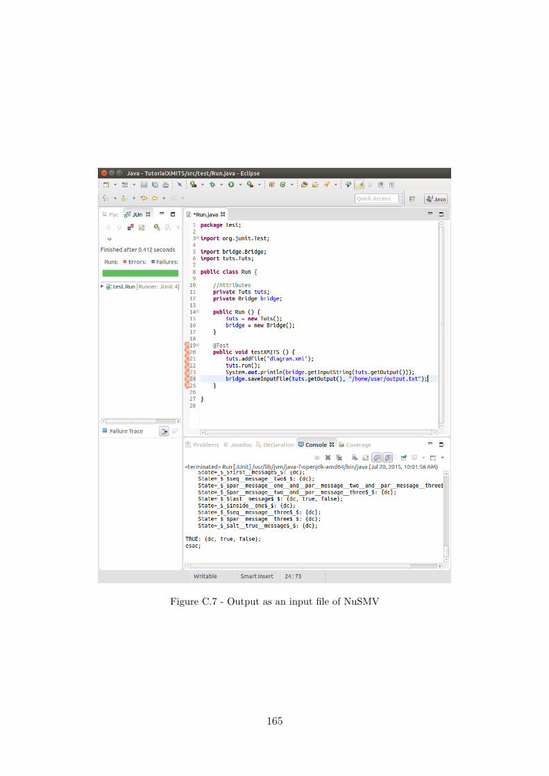
Figure C.7 - Output as an input file of NuSMV
165

Figure C.8 - Class Diagram of Reader Module
166

Figure C.9 - Class Diagram of Bridge Module
167

Figure C.10 - Class Diagram of Global Module
168

PUBLICAÇÕES TÉCNICO-CIENTÍFICAS EDITADAS PELO INPE
Teses e Dissertações (TDI) Manuais Técnicos (MAN)
Teses e Dissertações apresentadas nosCursos de Pós-Graduação do INPE.
São publicações de caráter técnico queincluem normas, procedimentos, in-struções e orientações.
Notas Técnico-Científicas (NTC) Relatórios de Pesquisa (RPQ)
Incluem resultados preliminares depesquisa, descrição de equipamentos,descrição e ou documentação de progra-mas de computador, descrição de sis-temas e experimentos, apresentação detestes, dados, atlas, e documentação deprojetos de engenharia.
Reportam resultados ou progressos depesquisas tanto de natureza técnicaquanto científica, cujo nível seja com-patível com o de uma publicação emperiódico nacional ou internacional.
Propostas e Relatórios de Projetos(PRP)
Publicações Didáticas (PUD)
São propostas de projetos técnico-científicos e relatórios de acompan-hamento de projetos, atividades e con-vênios.
Incluem apostilas, notas de aula e man-uais didáticos.
Publicações Seriadas Programas de Computador (PDC)
São os seriados técnico-científicos: bo-letins, periódicos, anuários e anais deeventos (simpósios e congressos). Con-stam destas publicações o InternacionalStandard Serial Number (ISSN), que éum código único e definitivo para iden-tificação de títulos de seriados.
São a seqüência de instruções ou códi-gos, expressos em uma linguagem deprogramação compilada ou interpre-tada, a ser executada por um computa-dor para alcançar um determinado obje-tivo. Aceitam-se tanto programas fontequanto os executáveis.
Pré-publicações (PRE)
Todos os artigos publicados em periódi-cos, anais e como capítulos de livros.