a midrange aluminum sheet metal intake manifold
TRANSCRIPT

A Midrange Aluminum Sheet Metal Intake Manifold
by
MARK LESAINT
Submitted to the MECHANICAL ENGINEERING TECHNOLOGY DEPARTMENT
In Partial Fulfillment of the Requirements for the
Degree of
Bachelor of Science In
MECHANICAL ENGINEERING TECHNOLOGY
at the
OMI College of Applied Science University_ of Cincinnati
May 2002
© ...... Mark LeSaint
The author hereby grants to the Mechanical Engineering Technology Department permission to reproduce and distribute copies of the thesis document in whole or in part.
Signature of Author
Certified by
Accepted by
A len Arthur, Thesis Advisor
aidi, PhD, Department Head Mechanic Engineering Technology

Abstract
Drag Racing is a sport, involving maximizing performance of a vehicle to
minimize travel time over a quarter of a mile on a drag strip. Aftermarket performance
parts can enhance a vehicle’s performance; however cost is large factor in part selection.
An intake manifold is an example of this. There are cast aluminum and sheet metal
aluminum intake manifolds available from several different companies. The problem lies
in the fact that these intake manifolds jump in price from $300 to $2500. This jump in
price is very unwelcome to drag racers.
The design objectives involved in creating an intake manifold were to be more
affordable than the current high price aluminum sheet metal intake manifold and perform
better than the low performance cast aluminum intake manifold. These objectives create
an intake manifold with a midrange price and performance. The benefit is giving drag
racers a third option when purchasing an aftermarket intake manifold.
The performance of the intake manifold was increased by designing for better air
flow. The performance is demonstrated by testing the airflow of the cast aluminum
intake manifold against the prototype on a flow bench. Eliminating machining and
welding time reduced the price of manufacturing. The final price per unit was found by
having a bid made by a sheet metal facility in the area based on a two hundred and fifty
unit order.
This newly designed and constructed aluminum sheet metal intake manifold
successfully met all design criteria. It performs twelve percent better than the cast
aluminum and is forty percent cheaper than the existing aluminum sheet metal intake
manifold. This prototype manifold gives drag racers a midrange option for upgrading
their intake manifolds.
ii

Table of Contents
Abstract………………………………………………………………………………ii List of Tables…………………………………………………….……………….…iv List of Figures………………………………………………………………………iv Introduction…………………………………………………………………………1 Design Solution…………………………………………………………….………..4 Air Flow………………………………………………….………………….4 Price…………………………………………………………………………5 General Design Parameters and Specifications……………………………..7 Building and Testing…………………………………………………………………8 Conclusion and Recommendations……………………………………………..….10 References……………………………………………………………………….…11 Appendices Appendix A – Survey……………………………………………………………A-1 Appendix B – Proof of Design…………………………………………………..B-1 Appendix C – Schedule………………………………………………………….C-1 Appendix D – Manufacturer’s Information………………………….………….D-1 Appendix E – Drawings………………………………………….……………...E-1 Appendix F – Vender Bid………………………………………………..………F-1 Appendix G – Charts of Test Results………………………………..………….G-1
iii

List of Figures
Figure 1 – Edelbrock “Victor”……………………………………………..…………….1
Figure 2 – Hogan’s Racing Manifolds “Sheet Metal Intake Manifold”……………..…. 1
Figure 3 – Superflow 600 FlowBench……………………………………..…………….8
iv

Introduction An intake manifold is a key component in an engine that transfers and divides the
air/fuel mixture from the carburetor into the ports on the cylinder heads. Modifying the
design of this manifold can increase the overall performance of an engine. Fuel is sent
from the cylinder heads into the combustion chamber. The fuel is then compressed and
ignited to produce an explosion forcing the piston down. The stronger this explosion, the
more power the engine is creating. Changing other components can enhance power
output also. The right combination of high performance components is a key factor in
maximizing overall performance. Changing cylinder heads can improve the fuel flow
and velocity into the combustion chamber but can lead to other problems. The air intake
and intake manifold are still designed for the original cylinder heads. Now the air intake
and the intake manifold become the most restrictive components. These two components
have to be replaced to allow a higher air/fuel mixture flow to best utilize the high
performance cylinder heads.
Aluminum is the material of choice for an upgrade from the stock cast iron intake
manifold. The problem lies in the fact that these aftermarket intake manifolds have a
large jump in price. The Edelbrock Victor (figure 1), which is cast aluminum, costs $300
and has low air flow. The sheet metal intake manifold available from Hogans Racing
Manifolds (figure 2) has higher air flow and a higher price of $2500. The large jump in
price is very unwelcome to drag racers. The solution is to create an intake manifold with
air flow and cost between the Edelbrock Victor and the Hogans Racing Manifold. [4,5]
Figure 2 – Sheet Metal Intake Manifold available from Hogans Racing Manifolds.
Figure 1 – “The Victor” A Cast Aluminum Intake Manifold available from Edelbrock.
1
A prototype that solves this problem will have to be completed and tested. The
prototype has to be set up for 1050cfm carburetor. This is the same carburetor that the
Edelbrock Victor is set up for; this sets up a fair test. For the prototype to be considered
a solution to the problem, test results have to prove that airflow and price will fall
between the two current aftermarket choices.
Based on an interview with Tom Bieckern, President of Midwest Fabricators, the
cost factors with the manufacturing of the intake manifold are time for welding and
machining. The materials are required regardless of the design, which takes materials out
of the factors that lower cost. Aluminum is around $1 per pound regardless of size or
shape (i.e. sheet metal, bar stock, etc.). Modifying a current design to require less
welding and machining reduces the price.[3]
The targeted customer for this product is an owner of Ford 460. Tri-state
Dragway and Edge Water Raceway are home to many drag racers in the area. These
racetracks visited were found to contained several potential customers. Several have
developed their own custom aluminum sheet metal intakes to fit their 460s based on the
design from Hogan’s Racing Manifolds. The Ford 460 is discontinued, but existing
blocks and parts are readily available. Many drag racers are interested in the intake
manifold as an upgrade to their existing manifolds providing the cost is beneath $2500.
Four Ford 460 owners filled out the survey in appendix A. The results of this survey will
guide the design process to accommodate the important needs of the customer. The
results were tallied and placed behind each question in Appendix A. [1,6]
The proof of design is located in appendix B. This is a written agreement that
illustrates exactly what the design criteria are for the project. One intake manifold will be
designed and constructed that is 15% cheaper than the aluminum sheet metal intake
manifold available from Hogan’s Racing Manifolds, while increasing performance over
the Edelbrock Victor intake manifold.
2

The cost is estimated for each unit based on production of two hundred and fifty
units. This estimate comes from a machine shop with the capability to produce this
manifold. The production number of two hundred and fifty was based on how many Ford
460 owners are known at the two tracks visited, multiplied by an estimate of how many
drag strips are in the country. This estimate on production is based on a assumption that
one out of every four 460 owners will buy this manifold. [1]
Flow bench testing will prove the performance increase. The resulting average
runner flow of the prototype manifold was proven and compared to the average runner
flow of the Edelbrock Victor cast aluminum manifold. This comparison showed a
twelve percent increase in air flow to the Edelbrock Victor. A schedule that includes
construction and testing is available in appendix C.
3

Design Solution
The design solution was broken into three areas: air flow, price, and general
design parameters and specifications. The proof of design in Appendix B says that a
prototype must be constructed with air flow and price being specific areas of
concentration. Other parameters of designing the intake manifold exist but are not
relevant to air flow and price, but to create a functional prototype.
Air Flow
High velocity and turbulent air flow are known to be important factors of high
performance by the professional drag racers at Edgewater Race Way and Tri-State Drag
Way. The Edelbrock Victor was analyzed to find good and bad design characteristics.
To create a high velocity system the prototype intake manifold has been designed
with a more direct path from the carburetor to the cylinder heads. The path will separate
in the plenum into 8 portions. This division will have no obstructions except the base
plate of the plenum and the runner bends. The Victor receives the air/fuel mixture from
the carburetor into the plenum. This plenum has runners connected on its sides. This
forces the mixture to take a ninety-degree corner, which slows the flow dramatically.
The next part of the flow is through the runners. The runners exit the plenum completely
horizontal then bend downward to meet the cylinder heads. Another corner is created in
the bend. The air/fuel mixture is forced make one hundred and thirty five degrees worth
of bends. These conditions are not favorable and must be modified in the prototype.
To correct this, the prototype has been designed with runners that connect to the
plenum with forty five-degree angles off the bottom. The runners also contain no bends
for little resistance. The new design only requires the air/fuel mixture to take 45 degrees
worth of bends. This is much more favorable than the 135 degrees currently required by
the Edelbrock Victor.
4

The increase in velocity is a factor of area in the tapered runners. The taper
decreases the cross-sectional area of the runner using the following formula.
AreaFlowRateVelocity = . This is the formula that illustrates the rise in velocity is directly
proportional to the area. The new prototype and the Edelbrock Victor contain similar
tapers. The reduction in area is the same but method to accomplish the taper is
completely different. [7]
The Victor’s runners keep a constant width while the height of the cross-section
decreases. The end of the runner transitions into an oval. The prototype’s design has a
large area circle that gradually tapers and transitions into an oval. Using the taper to also
transition the runner is a common design characteristic shared between several intake
manifolds. [4,5]
The base of the plenum is a ‘V’ shape. This will help to create a pocket in the
middle of the runners that will feed the runners. The flow of the carburetor is higher than
the flow required by the engine, which will let this fuel/air pocket develop. The plenum
had three designs initially. All three were built from cardboard and tested to see which
had the best flow characteristics. This plenum was then built out of aluminum and added
to the assembly.
Price
The materials required to produce this intake manifold were very inexpensive.
The aluminum was approximately two hundred dollars for the prototype. Reducing cost
is solely based on the amount of machining and welding time that can be reduced.
The base of the manifold is designed after the Edelbrock Victor base. Instead of
the cast base, the current design uses one piece of aluminum sheet metal to form the
mating surface to the engine. The high-grade aluminum will stand up better to vibration
than the cast aluminum thereby increasing the resistance to fail during operation. The
5

one piece of aluminum required is very inexpensive to have cut out by a water jet cutter.
The prototype was $79 for just the base. The bending required takes only two minutes.
No machining is required to the base after construction.
The cost is an important factor in this project, so the taper has gone through
several design concepts. The most inexpensive method of acquiring a taper was selected.
After the runner is welded to the base, it was filled with a high-temperature epoxy that
was machined into the taper. This taper is also where the runner begins the transition
from a circle to an oval, which is the shape of the port on the head. This allowed the
design to utilize a standard constant diameter aluminum tube. This tube was $20 for
twenty feet. The tube was simply band saw cut to the length required. The epoxy was
$200 for two gallons. This is enough epoxy to make approximately six intake manifolds.
The epoxy selected had to be able to stand up to gasoline, handle high temperature, bond
to aluminum, and be machineable. Product #641 from Epoxy Systems Int. (appendix D)
was selected. After one runner was filled with epoxy a wax mold could be made of the
ported runner. This mold could be used in the other runners and the epoxy would be
poured in around it. After the epoxy set up the wax mold could be melted out. The
production of the runners would be very inexpensive and cost effective.
The plenum was also designed for assemble. The drawings in appendix E show a
flat pattern for the plenum. The long sides of the plenum are bent into the final shape and
the shorter end caps are welded on. This requires very little welding. The plenum is thin
and can be laser cut.
The adapter plate is simply a flat sheet of aluminum. This sheet is laser cut and
bolts onto the top of the plenum. No welding is required to attach the adapter plate.
Another benefit to this design gives the intake manifold operator an easy way to change
adapter plates for different carburetors, blowers, or even fuel injection. This is a
favorable design characteristic to the drag racers interviewed and surveyed.
6

Every component of this intake manifold has been reduced in cost from the
current production intake manifold. The base plate is bolted to an engine block while the
runners are welded. The plenum is then welded to the top of the runners. The material is
very thin and welds easily. No machining is required after assemble except porting the
runners. The key element that makes this method effective is that there was no harm to
the function of the intake manifold to produce it forty percent less expensive than the
current aftermarket sheet metal intake manifold.
General Design Parameters and Specifications
The type of aluminum used is a combination of 6061 T6 and 5052 H32. 6061 T6
is aircraft grade aluminum. The T6 means this metal has steel added for strength. This
material will be good for any flat plates in the manifold. It is not suitable for the bending
found in the plenum design. 5052 H32 is more pliable. It is non-ferrous and strain
tempered for strength. Both types of aluminum are readily available in sheet form and
have a thickness tolerance of plus or minus .013 inches. [3]
The weld strength is based on the size of the welds. The welds for this project
will produce a bonded area that will be equal to or greater than the thickness of the
aftermarket intake manifolds. This takes most stress concerns out of the project. The
only stress seen by the intake manifold is vibration stress and thermal stress. The
expertise of the welders at Midwest Fabricators will be required to ensure the welds are
strong with ample penetration and no leaks. The top of the engine will reach a
temperature of no higher than two hundred and fifty degrees Fahrenheit. This small
amount of heat is negligible when expansion due to heat is calculated. The design of the
intake manifold allows for expansion in any direction with the help of the cylinder head
gasket. Intake manifolds and cylinder heads can maintain a tight bond with heat applied
in various areas. This is proven also by the long history of drag racing. [3]
7
Building and Testing
The side plates of the intake manifold base are very complex with fillets,
chamfers, and angles. Rather than sending a detailed drawing with a complex dimension
scheme another approach was taken. The dimensions from the existing manifold were
taken carefully with a scale and Venire Caliper. In AutoCAD 2002, a two dimensional
sketch was created. The sketch was printed out on a Hewlett Packard Plotter accurate to
four decimal places. The plotted drawing was cut out carefully and compared to the
existing intake manifold. This was done three times until all fillets, chamfers, angles, and
holes matched accurately. The electronic sketch was then converted to a DXF format.
This format is compatible with the water jet cutter. The water jet cutter is accurate to five
decimal places. The file is loaded into an interface and the computer finds the best cut
pattern for the parts. The base was created with no drawings. The sketches of the base
are available in Appendix E.
The plan for construction was to build the base and runners immediately. Three
plenums of various designs were constructed from cardboard to find which configuration
produces the highest flow. The flow characteristics will be determined from flow bench
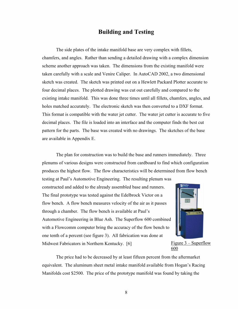
testing at Paul’s Automotive Engineering. The resulting plenum was
constructed and added to the already assembled base and runners.
The final prototype was tested against the Edelbrock Victor on a
flow bench. A flow bench measures velocity of the air as it passes
through a chamber. The flow bench is available at Paul’s
Automotive Engineering in Blue Ash. The Superflow 600 combined
with a Flowcomm computer bring the accuracy of the flow bench to
one tenth of a percent (see figure 3). All fabrication was done at
Midwest Fabricators in Northern Kentucky. [6] Figure 3 – Superflow 600
The price had to be decreased by at least fifteen percent from the aftermarket
equivalent. The aluminum sheet metal intake manifold available from Hogan’s Racing
Manifolds cost $2500. The price of the prototype manifold was found by taking the
8

finished product, drawings, and specifications to the company president, Don South. He
produced an estimate for what it would cost for Midwest Fabricators to produce two
hundred and fifty units and make a profit. [5]
Test Results from the flow bench testing on May 15th show the Edelbrock Victor
at an average runner velocity of 510 cubic feet per minute. The prototype manifold had
an average runner flow rate of 611 cubic feet per minute. The estimated price of the
prototype manifold based on production of 250 is $1500 per unit from Don South at
Midwest Fabricators (appendix F). A cost comparison and flow rate comparison chart is
available in appendix F.
9

Conclusion and Recommendations
Applying the methods of construction found in the research portion of the project,
an aluminum sheet metal intake manifold was constructed that performs better than the
Edelbrock Victor cast aluminum intake manifold by twelve percent. This completed
project will cost forty percent less to produce than the aftermarket intake manifold
available from Hogan’s Racing Manifolds. This completes all design requirements in the
Proof of Design (appendix B).
The completed intake manifold will allow drag racers another choice when
selecting a level of performance. Every drag racer interviewed has agreed that the
aluminum sheet metal intake manifolds available are too expensive. By manipulating the
design of the current aluminum sheet metal intake manifold, the cost of manufacturing
this aftermarket has been reduced. The background in drag racing, Midwest Fabricators,
Paul’s Automotive Engineering, and knowledge gained in classes at The University of
Cincinnati have lead to a less expensive design that was constructed and tested. The test
results in the previous section and Appendix G prove that a midrange aluminum sheet
metal intake manifold has been created.
Customer input has been a driving factor in several design characteristics. After
reviewing the final product a recommendation was made. Finding a way to lengthen the
runners would have a huge benefit to the air flow. The flow could reach a higher velocity
by the end of the runner which would ultimately result in an increase in torque. It is very
important to always find ways to produce products as inexpensively as possible.
Reducing machining and welding time is the key to lowering the manufacturing cost.
Any new ways to produce a part cheaper without sacrificing quality or function are
strongly recommended.
10

References
1. Ken Herbert, Tony Mann, Bill Chambers, and Tim Chardine - Professional Drag
Racers
2. Pak/Teem Inc. – Keith Sumey, Shop Manager
3. Tom Bieckern, Don South – Midwest fabricators
4. www.Enderle.com
5. www.Hogansracingmanifolds.com
6. Paul’s Automotive Engineering – Paul
7. Introduction to Fluid Mechanics, William S. Janna. PWS Publishing Co., 1993.
11

Appendix A
Survey
Survey for Ford 460 owners with cobra-jet heads 1=not satisfied 2=somewhat satisfied 3=satisfied 4=very satisfied 5=extremely satisfied How satisfied are you with your current intake manifold? 1 2 3 4 5 3 How satisfied are you with the current price of aluminum sheet metal intake manifolds between $2000 and $2500? 1 2 3 4 5 2 How satisfied would you be with aluminum sheet metal intake manifold that costs under $800 that had a 70% weight reduction from the stock manifold? 1 2 3 4 5 5 How satisfied would you be with an Aluminum sheet metal intake manifold that was setup for rpm’s of 7000 or higher that costs less than $800? 1 2 3 4 5 5 How satisfied would you be paying less than $800 for an aluminum sheet metal intake manifold that increases engine performance up to 10%? 1 2 3 4 5 4.75 Comments The Cheaper the better
A-1

Appendix B
Proof of Design
B-1

B-2

Appendix C
Schedule
C-1

Sche
dule
for P
roje
ctR
evis
ed o
n 1/
10/0
2
Mon
thSe
ptem
ber
Oct
ober
Nov
embe
rD
ecem
ber
Janu
ary
Febr
uary
April
May
June
Dat
e20
-22
23-2
930
-67-
1314
-20
21-2
728
-34-
1011
-17
18-2
425
-12-
89-
1516
-22
23-2
930
-56-
1213
-19
20-2
627
-23-
910
-16
17-2
324
-23-
910
-16
17-2
324
-30
31-6
7-13
14-2
021
-27
28-4
5-11
12-1
819
-25
26-1
2-8
9-15
Assi
gnm
ent
1 Pa
ge P
robl
em D
efin
ition
`
Dra
win
gs w
ith D
imes
ions
Con
cept
s
Proo
f of D
esig
n
Inte
rim D
esig
n R
epor
t
Mar
ch
3 Pr
oble
m D
efin
ition
s
Surv
ey
Prop
osal
Advi
sor P
roof
of D
esig
n
Des
ign
Free
ze
Tech
Exp
o
Fina
l Rep
ort
Ora
l Pre
sent
atio
n
Con
stru
ctio
n
Bill
of M
ater
ials
C-2

Appendix D
Manufacturer’s Data
D-1

D-2

Appendix E
Drawings and Sketches DWG1ASSY.DWG DWG2BASETEMP.dwg DWG3RUNN.dwg DWG4TOP.dwg
E-1

Appendix F
Vender Bid
F-1

F-2

Appendix G
Charts of Testing Results
G-1

G-2
Chart 1 - Prototype versus Edelbrock Victor
0
100
200
300
400
500
600
700
1 2 3 4 5 6 7 8
Cylinder #
Air
Flow
(CFM
)
Edelbrock VictorPrototype
Chart 2 - Price Comparison
$0.00
$500.00
$1,000.00
$1,500.00
$2,000.00
$2,500.00
$3,000.00
Hogans RacingManifold
Prototype IntakeManifold
Edelbrock Victor
Intake Manifold
Pric
e