a model-based sensor fusion approach for force and shape
TRANSCRIPT

HAL Id: hal-02882039https://hal.inria.fr/hal-02882039
Submitted on 26 Jun 2020
HAL is a multi-disciplinary open accessarchive for the deposit and dissemination of sci-entific research documents, whether they are pub-lished or not. The documents may come fromteaching and research institutions in France orabroad, or from public or private research centers.
L’archive ouverte pluridisciplinaire HAL, estdestinée au dépôt et à la diffusion de documentsscientifiques de niveau recherche, publiés ou non,émanant des établissements d’enseignement et derecherche français ou étrangers, des laboratoirespublics ou privés.
A Model-based Sensor Fusion Approach for Force andShape Estimation in Soft Robotics
Stefan Escaida Navarro, Björn Hein, Stefan Escaida Navarro, Steven Nagels,Hosam Alagi, Lisa-Marie Faller, Olivier Goury, Thor Morales-Bieze, Hubert
Zangl, Bjorn Hein, et al.
To cite this version:Stefan Escaida Navarro, Björn Hein, Stefan Escaida Navarro, Steven Nagels, Hosam Alagi, et al..A Model-based Sensor Fusion Approach for Force and Shape Estimation in Soft Robotics. IEEERobotics and Automation Letters, IEEE 2020, 5 (4), pp.5621-5628. �10.1109/LRA.2020.3008120�.�hal-02882039�

A Model-based Sensor Fusion Approach for Force and ShapeEstimation in Soft Robotics
Stefan Escaida Navarro1, Steven Nagels2,3, Hosam Alagi4, Lisa-Marie Faller5, Olivier Goury1,Thor Morales-Bieze1, Hubert Zangl6, Bjorn Hein4,7, Raf Ramakers8, Wim Deferme2,3, Gang Zheng1
and Christian Duriez1
Abstract— In this paper, we address the challenge of sensorfusion in Soft Robotics for estimating forces and deformations.In the context of intrinsic sensing, we propose the use of asoft capacitive sensor to find a contact’s location, and theuse of pneumatic sensing to estimate the force intensity andthe deformation. Using a FEM-based numerical approach, weintegrate both sensing streams and model two Soft Roboticsdevices we have conceived. These devices are a Soft Pad and aSoft Finger. We show in an evaluation that external forces onthe Soft Pad can be estimated and that the shape of the SoftFinger can be reconstructed.
I. INTRODUCTION
The emergence of Soft Robotics has brought about a newstream of ideas in the domain of sensing. The challengeto sense external forces and the shape of these deformablerobots has spawned many new sensor designs and the use ofnovel sensing principles. Meanwhile, estimating the state ofa soft robot based on multi-modal sensing streams is an openchallenge. In general, approaches for sensing can be foundthat use learning-based, analytical and numerical methods.
In this work, we follow up on our previous work onmodel-based pneumatic sensing [1] and we explore the ideaof model-based sensor fusion to address force and shapesensing in Soft Robotics. The central idea of this approach isto use a numerical model, which allows to differentiate themeasurement of deformation from what causes it. To this
This work was supported by the Region Hauts-de-France, the project CO-MOROS (ANR-17-ERC2-0029), the European Regional Development Fund(ERDF), ROBOCOP (ANR-19-CE19-0026) and the project Inventor (I-SITEULNE, le programme d’Investissements d’Avenir, Metropole Europeennede Lille). It was also supported by the Federal Ministry of Education andResearch (Bundesministerium fur Bildung und Forschung, BMBF) withinthe project (Verbundprojekt-Nr.: 16SV7823K:) and Project of Departmentof Education of Guangdong Province (No.2019KZDXM037).The authorswould like to thank the students Carlos Lagarde, Manuel Sanchez, FlorentChochoy and Pierre Sens for their engineering contributions to this work.
1Authors are with team DEFROST at Inria Lille - Nord Europe andCRIStAL - Centre de Recherche en Informatique Signal et Automatique deLille, France, contact: [email protected]
2Author is with Hasselt University, Institute for Materials Research (IMO)3Author is with IMEC vzw, Division IMOMEC4Authors are with Institute for Anthropomatics and Robotics - Intelli-
gent Process Control and Robotics Lab (IAR-IPR), Karlsruhe Institute ofTechnology
5Author is with Institute for System Engineering and Systems Design -Robotics Lab, Carinthia University of Applied Sciences
6Author is with the Institute of Smart System Technologies, Sensors andActuators Department, Alpen-Adria-Universitat Klagenfurt
7Author is with the Karlsruhe University of Applied Science8Author is with Hasselt University, Flanders Make, EDM
Fig. 1: In this work, we present two devices, a Soft Pad anda Soft Finger, that include capacitive and pneumatic sensing.Capacitive sensing allows us to find contact locations andpneumatic sensing to measure the amount of deformation.Sensor fusion is mediated by a numerical model (FEM),which allows us to estimate the forces being applied andthe deformation of the devices.
end, we use capacitive and pneumatic sensing. We employcapacitive sensing for detecting the location of external con-tacts and pneumatic sensing for quantifying the deformation.We provide two example devices that display the principlesof the proposed approach (see Fig. 1, for dimensions Fig. 5):
• A Soft Pad that has a deformable electrode arrayembedded in its upper layer and embedded cavitiesunderneath. The electrode array allows the detection ofcontact location, while the cavities allow for quantify-ing the amount of deformation by measuring volumechanges. Using both sensing streams and the model, thecontact’s location, the contact’s force and the resultingdeformation can be estimated.
• A Soft Finger that has electrodes on its segments andpneumatic cavities between its segments. The electrodesallow for detecting contacting objects, while the cavitiesagain allow sensing the amount of deformation. In ad-dition, the finger is actuated by a cable, which can also

be considered by the model. Therefore, the sensing ofexternal contacts can take into account the deformationalready caused by the actuation.
For the Soft Pad, we evaluate the performance of the contactlocation and the force estimation. For the Soft Finger, weshow that external contacts can be detected reliably andprovide an evaluation for the estimation of the deformation.The results for both platforms are encouraging to further pur-sue this sensor fusion approach. A video accompanying thispaper illustrates these approaches and provides additionalexample interactions to the ones presented here.
The remainder of the paper is structured as follows: In thenext section, we review the related work from the field. InSec. III, we describe the devices we fabricated and how weobtain capacitive and pneumatic measurements respectively.In Sec. IV, we describe our modeling approach and howit allows us to fuse the sensor streams. Then, in Sec. V,we provide an experimental validation using the proposeddevices. Finally, in Sec. VI, we summarize our contributionsand give a perspective on future research ideas.
II. RELATED WORK
A variety of measurement principles/physical effects havebeen shown to work for tactile sensing and shape sensing indeformable materials. Pneumatic sensing is a popular optionfor tactile sensing. One of its advantages is, that it allowssensing and actuation at the same time, as shown in [2]. Theauthors implemented a soft pad that can sensorize a robot’senvironment and provide cues for grasping by estimatingthe center-of-mass and orientation of an object, all whilehaving variable stiffness. Our own previous work [1] usesembedded air chambers for detection of location. However,these approaches do not scale very well in terms of thenumber of sensing points, compared to capacitive sensing,e. g. [3]. This is due to the bulky instruments, valves andtubing involved. One technology that has received significantattention in recent years in sensor designs is using liquidmetal, i. e. gallium-indium-tin, Galinstan. The liquid can beembedded in microchannels inside soft structures. Dependingon the geometry of the channels, changes in strain or tactilepressure bring about changes in resistance for example [4].Another significant trend is the development of additivelymanufactured sensors [5], where the authors show a flexibledesign inspired by the rigid electrode layouts prevalent inconsumer-electronics. In this work, we follow up on [5],but this time we use Galinstan to fabricate deformablecapacitive touch-pads, which exhibits great deformability andis therefore better suited for our use-case [6].
Regarding shape sensing, some interest is directed towardsoptical sensing principles, like Ledermann et al., who havestudied the use of optical fibers, e. g. [7]. For shape sensing,even capacitive sensing has been studied recently by Scimecaet al. [8]. The authors propose to use a capacitive tactilearray at the base of a soft finger segment, sensing pressuredistribution in order to estimate the pose of the tip usinga feed-forward neural network trained using visual tracking
data. However, these approaches do not include measuringof external contacts to estimate the resulting deformations.
Works close to our approach in terms of multi-modalsensing are due to Truby et al. [9], Soter et al. [10] and Yanget al. [11]. Truby et al. show a complex sensorization of a softfinger, featuring a bending sensor, an inflation sensor and acontact sensor on the finger-tip. The bending measurement isshown to be independent of the inflation readings, meaningthat it is possible, in principle, to estimate the bending radiusindependently of the pressure used for actuation, for instance,when the finger contacts an object. However, their workonly shows results for regressions and does not deal withmultiple interactions along different directions. Soter et al.propose a design in which cavities inside a soft pad arefilled with a colored liquid [10]. A display showing the levelof the liquid in the cavity is used to monitor touch andbending interactions on two different devices. In terms ofmodeling, the sensor is identified at a single pressure pointor bending along one direction through regression. Yang etal. [11] conceive a pneumatic sensor in the shape of a cuboidmade out of silicone. They model the deformation of thewall carrying a weight similar to a beam. They find thebeam deformation that best explains the pressure throughthe volume change, which results in the estimation of theforce/weight. The same pneumatic sensor is then used todetect curvature by means of a geometric model (not abeam). However, this approach lacks an integration strategy,where shape and force can be estimated using the samemodel.
In general, a proficient approach for integrating multiplesensor streams is still missing. We propose a method which isentirely model-based, i. e. that does not rely on learning, andthat leverages this model to fuse multi-modal sensor streamsin order to estimate forces and deformations. Learning canachieve high levels of accuracy, e. g. [8]. However, thefeature-space used for learning grows exponentially for eachadditional sensor added to device. Meanwhile, a model-basedapproach scales well with the number of sensors, becauseadding further constraints that represent them in the modelis low cost (see Sec. IV). Finally, the presented model-based approach easily adapts to changes in the design of thedevices, whereby the learning effort could be wasted uponredesign.
III. SENSING
A. Capacitive Sensing
Two main realizations of capacitive sensing are possible:single-ended or self-capacitive (see Fig. 2 (left)) and mutual-capacitive (see Fig. 2 (right). In single-ended sensors, an AC-voltage is applied to a send-electrode (Tx). This potential isresponsible for an electric field that couples into any nearbyconductors or objects capable of draining the electric field(such as, e. g., the human body). In the example of Fig. 2, thesensor couples mainly to a human finger, which is consideredas a conductor that has an impedance Z to ground. Someof the coupling in this scene is static (in blue) and some issubject to change as the human finger moves. Changes in the

~E
φ1
Tx
Groundφ0
Z
Ground
~E
φ1
φ0
Rx Tx
φ′0
Z
Fig. 2: Single-ended mode (left): The electrode is drivenwith an electrical potential and generating an electrical fieldbetween the measurement electrode and the object. Mutual-capacitive mode (right): the right electrode transmitter or Txis driven, generating an electrical field, which ends at receiveror Rx. A conductive object within the measurement rangeblocks/shields the field lines (green) between the electrodes.
Ele
ctro
des
Fig. 3: Left: An array of electrodes made out of Galinstanworked into a deformable silicone sheet. Middle: A 4×4version of the Soft Pad. Right: A transparent version of theSoft Finger where the size and location of the electrodes isshown.
coupling will be reflected by changes in the amplitude of themeasured send current. Static coupling, also called parasiticeffects, will cause an offset value. To guide the coupling toa desired region in the sensing area, active-shielding can beemployed.
In mutual-capacitive sensors, two kinds of electrodes areconnected to the sensing unit, send (Tx) and receive (Rx).Again an AC-voltage is applied to Tx and the potential ofRx is brought close to ground. Therefore, an electrical fieldis built up between the two electrodes, which is responsiblefor a displacement current that is usually measured at Rx.In Fig. 2 (right), it is shown that a human finger, being aconductive object with a connection to ground, will draina certain amount of field lines between Tx and Rx. In thiscase, the displacement current will drop. This is the so-calledshielding effect due to the object. The complementary effect,coupling, can be observed in tactile sensing elements wherethe electrode distance changes due to external forces. Theelectrodes approaching each other leads to an increase ofthe displacement current, as described e. g. in [3].
B. Sensing Elements, Electronics and Fabrication
In this work, there are three capacitive sensing elementsbeing used, which are shown in Fig. 3. We have developedan 8×8 pad, a 4×4 pad and the sensors embedded in the Soft
Sensor Module 1
Clk
Capacitive Image
64m
m
Sensor Module 2
Fig. 4: Left: The interlocking diamond-pattern in which theelectrodes are arranged including overall size information.Right: A capacitive image obtained using single-ended mea-surements when pressing on the Soft Pad as seen in Fig 1.
Finger. The sensitive area of the 8×8 pad has the dimensionsof 64×64mm2 (see Fig. 4). The 8×8 array included in theSoft Pad and the electrodes inside the Soft Finger are drivenin single-ended mode and are used in the main evaluationof the proposed approach. The 4×4 pad is driven in mutual-capacitive-mode to investigate multi-touch. The electronicshardware used for the 8×8 pad and the Soft Finger in thesingle-ended mode were previously described in [12]. Thehardware used for the 4×4 pad in mutual-capacitive modewas previously presented in [13].
The capacitive sensing elements of the Soft Pads useGalinstan liquid metal electrodes encased in silicone rub-ber to allow for great deformability. They are made usingan openly accessible, Do-It-Yourself fabrication approach,called Silicone Devices, which does not require any advancedmachinery, except for a CO2 laser cutter [6]. Circuit compo-nents (in this case, only connectors) were first fixated on thesurface of a silicone sheet. Next, on top of these connectors,a stencil is laser cut in place out of vinyl sticker. Galinstanis then stencil-patterned into a first layer of the interlockingdiamond design and subsequently overmolded with siliconerubber. The second layer of the design is then created byrepeating the steps. All consumable items can be readilypurchased online, as detailed in the fabrication approach’saccompanying Instructable.1
C. Implementing a Capacitive Touch-Pad
In Fig. 4 (left), the schematic of the 8×8-pad is shown.Two capacitive sensor modules with 8 channels each areused to perform the capacitive measurement in single-endedmode. The modules are synchronized with a clock signal toreduce cross-talk effects between them. Every column androw are driven with an AC exciter signal with a frequencyaround 100 kHz and a peak-to-peak amplitude of 5 V. Thecorresponding changes in the amplitude due to the presenceof an object at the pad is calculated and provided at 100 Hz.In fact, each row and column detects the finger beforecontact. By applying the outer product to the collectedreadings scol of the columns and srow of the rows, that isImg = scol ⊗ srow, a capacitive image is generated with the
1https://www.instructables.com/id/Silicone-Devices/

48 490
100
20406080
120
Pad
Volu
mes
(uL)
1413Time (s)
0
2
-1
1
3
Fing
er P
ress
ures
(kPa
)
150mm
121m
m
Fig. 5: Distribution of the cavities inside the Soft Pad andthe Soft Finger, example signal values from the deformationsseen in Fig. 1 and dimensions of the devices.
resolution of 8× 8 (see also [5]). Fig. 4 (right) shows theresulting image when a finger touches the pad (see Fig. 1).Further examples are shown in the video attachment. Toestimate the location of an external contact, the readings ofthe columns and the rows are interpolated independently toyield the x and y coordinate respectively, assuming that onlyone touch event occurs at a time.
D. Pneumatic Sensing
Regarding pneumatic sensing, we use two types of sensorsin this work. The time-integrated values of air-flow sensorsare used to directly measure the changes in volume of thecavities inside the Soft Pad, as in our previous work [1].There, we provided a detailed account of the sensing princi-ple including sensitivity, hysteresis and repeatability. Pres-sure sensors are used to measure the pressure change incavities inside the Soft Finger. The structures of the cavitiesand example signals are shown in Fig. 5. In the case of theSoft Pad, the structure of the cavities is aimed at covering thesensitive area in a uniform way, i. e. approximately uniformlydistributed sensitivity with respect to touch. Highly non-uniform sensitivity is more difficult to model, as seen laterin Sec. V-A. In the case of the Soft Finger, the cavity shapeand distribution are responsible for sensitivity along the twodesired bending directions (in the lateral and frontal planes).We arrived at these designs through experience as well astrial and error, but we think that an automated approach couldhelp in finding optimized shapes for the given tasks in thefuture.
The air-flow sensors used are the D6F-P0001A1 by OM-RON Corp. One great advantage they have is, that theyare suitable for a large range of force measurements, asthey do not saturate at a certain force level, like a pressuresensor would, while maintaining a high resolution. One oftheir main weaknesses is a drift-effect that appears overtime, which is reflected by the hysteresis [1]. This can becircumvented on the Soft Pad by resetting the integrationevery time the user releases the finger from the pad. However,this drift can not be dealt with by re-initialization in the caseof the Soft Finger. Therefore, we decided to fall back tousing the NXP Semiconductors MPX5100 absolute pressuresensors, which have no noticeable drift.
~v3
p3 p4p5
p1 p2
~v1 ~v2 ~v4 ~v5
Fig. 6: In SOFA, actuation forces can be distributed to anynumber of points on the FEM-mesh.
IV. NUMERICAL MODELING TECHNIQUES
In this section we describe the numerical model that isimplemented in our simulation framework SOFA2.
A. Online Finite Element Modeling (FEM)
We use the FEM, which yields the internal elastic forcesF(q), given that the nodes of the FEM mesh are at positionsq (see Fig. 1 right). In SOFA, we use a formulation thataccounts for the geometric non-linearities of the deforma-tion and the material is characterized by the Hooke’s law(Young’s modulus and Poisson’s ratio). During each step iof the simulation, a linearization of the internal forces iscomputed:
F(qi)≈ F(qi−1)+K(qi−1)dq, (1)
where dq = qi− qi−1 is the displacement of the nodes andK =
∂F(qi−1)∂q is the tangential stiffness matrix for the current
node positions q. To complete the picture, external forces areincluded:
0 =−K(qi−1)dq+P+F(qi−1)+HTλ . (2)
HT λ is a vector that gathers boundary forces, such ascontacts or external controlled inputs, e. g. cable actuators.The size of λ is equal to the number of rows in H andto the number of actuators (contact forces, cables, etc.). Prepresents known external forces, such as gravity. Then, (2) issolved under the assumption of static equilibrium, deliveringa motion that is a succession of quasi static states. Pleaserefer to [14] and [15] for a more in-depth discussion aboutthe FEM formulation used here.
B. External Forces Actuation
In SOFA, it is possible to model external force actuatorsthat simply apply forces on some nodes of the FEM-mesh. Inthis work, this force actuation is used to represent the pushingon the Soft Pad or the Soft Finger. The actuation magnitude isgiven by the pressure variable λ f , which can be distributedto a number of points pi on the FEM-mesh, as shown inFig. 6. In this work, it is the capacitive sensors that drive thelocation of the applied force and therefore the selection of thepoints. Each resulting force ~Fi is determined by the pressureλ f and the 3D distribution ~vi on nodes, i. e. ~Fi =~viλ f . Thedistribution is gathered in a row matrix H f = [..., ~vT
i , ...],so that the expression HT
f λ f represents the force actuationin (2).
2https://www.sofa-framework.org/

p5 p4 p3 p2 p1 ppullp6
~Fλc dc~vi,api
~vi,b~vi,c
Fig. 7: Illustration of the modeling of cable actuation inSOFA on the example of a deformable finger (the figureis adapted from [15]).
In modeling the Soft Pad’s indentation, we have set theactuation directions all perpendicular to the sensor surfaceand distribute the actuation magnitude equally among allaffected points in a certain radius, to match the indenter (seeFig. 8). In the example of the Soft Finger, we use up to twoforce actuators, each one applied to a single point.
C. Cable Actuation
Another one of the actuation modalities available in SOFAare cables. Here we recapitulate on a previous paper [15],where the approach to cable actuation was previously ex-plained. A cable in SOFA is specified by a series of pointspi where the cable is attached to the FEM-mesh, as illustratedby Fig. 7. A special point defined outside the FEM-mesh isppull , where the displacement/force is being applied. Here,we illustrate the cable actuation displacement dc as beingapplied by a rack and pinion system, like it is actually used inthis work. The displacement translates to a force ~Fλc , havinga magnitude λc.
As in Sec. IV-B, each point pi is the placement for aforce constraint on the FEM-model. This time, the directionof the constraint is found as the difference between the cabledirection after and before pi (see Fig. 7):
~vi,c = ~vi,a− ~vi,b. (3)
Like before, all the constraints are gathered in the row Hc =[..., ~vT
i,c , ...], so that the expression HTc λc represents the cable
actuation in (2). The total cable length is calculated as
δc(p) =N−1
∑i=0‖pi+1− pi‖. (4)
D. Transforming Pressure Measurements to Volumes
The force and shape estimation method is currently basedon volume information as inputs, not pressures. As we areusing pressure sensors in the Soft Finger, it is necessaryto transform pressures to volumes. For now, we use theassumption that the pressure inside the cavities of the Fingerdoes not significantly affect the shape of the cavity whenit is being compressed by the external forces or action ofthe cable. In other words, we do not currently model theforces due to the pressure inside the pneumatic cavities,which in general could affect their shape. This is, however,
an acceptable simplification for the setup we use, as themeasured pressures are in the lower kPa-range (see forexample Fig. 5). This way, we use the ideal gas law totransform from pressure readings to volumes:
PV = nRT, (5)
where P is the pressure, V the volume, n the number of molesof gas, R the ideal gas constant and T the temperature. Weassume furthermore that we have constant temperature, sothat the right hand side of (5) is in fact constant. For theinitial conditions we get:
P0V0 = nRT =C. (6)
Therefore, the relationship between pressure and volume fora measurement is:
∆V =C
(P0 +∆P)−V0. (7)
E. Finding Forces and Cable Displacement through Opti-mization
Using inverse problem solving [15], we can optimize forthe actuation (force, cable) that best explains the volumechanges inside the pneumatic sensors of the Soft Pad and SoftFinger (see Sec. III-D). The readings of the Soft Finger areconverted according to (7) from the pressure measurement.Let Φi(q) be the function that maps the positions of thenodes of the FEM-mesh to the volume of a pneumatic cavitywith index i ∈ {1,2, . . .}. Φi(q) can be calculated using thetriangles of the mesh defining the cavity and is alreadyimplemented in SOFA.
The actuation forces due to pushing or the cables are givenby ∆λ = (∆λ f 1, . . . ,∆λc1, . . .)
T . To find the relation betweenthe change in applied forces and the change in the (simulated)volume ∆Vi,sim of one pneumatic sensor we can write:
∆Vi,sim =∂Φi(q)
∂qK−1HT
∆λ . (8)
Therefore, first the changes of forces are mapped to the cor-responding nodes through HT , as discussed in Sections IV-Band IV-C. The tangential compliance matrix K−1 transformsthese forces to (FEM-)node-displacements, which finally canbe mapped to changes in volume through the derivative of Φ
with respect to q. For conciseness, we rewrite ∂Φi(q)∂q K−1HT
as Wi,va, which is the matrix that directly maps changes inactuation force to changes in volume. Now, we can for-mulate the optimization problem. We want to minimize thedifference between the simulated volumes ∆Vi,sim =Wi,va∆λ
and the real changes in volume ∆Vreal = (∆V1, . . . ,∆VN)T =
Wva∆λ :
∆λout = argmin∆λ
‖Wva∆λ −∆Vreal‖2,
s.t. ∆λmax ≥ ∆λ ≥ 0.(9)
Finally, we write out the squared expression. There, weignore the constant term corresponding to ∆V T
real∆Vreal forthe optimization:
∆λout = argmin∆λ
(∆λTW T
vaWva∆λ −2∆λTW T
va∆Vreal). (10)

Fig. 8: Experimental setup for the Soft Pad.
Fig. 9: Distribution of the estimated contact locations for alldata points.
This quadratic program (QP) is solved using a QP-solverwith the method presented in [15]. If the force is appliedby a cable, once we have found ∆λout and applied it to themodel, we can simply use (4) to find the corresponding cablelengths δc, which in turn gives us the displacements dc.
In summary, this modeling approach allows to seamlesslyintegrate the information from the capacitive sensors (push-ing location), the information from the pneumatic sensors(amount of deformation) as well as cable actuation to re-construct the force acting on deformable structures. Thenumerical model mediates the sensor fusion. Beyond that,an estimation of the deformed shape is obtained.
V. EVALUATION
A. Soft Pad
To evaluate the performances of the presented approach,we have performed an experiment designed to test theaccuracy of the localization and force reconstruction (seeFig. 8). To this end, the Soft Pad was sampled in a regulargrid of 10×10 (100 times) in three different force levels:∼5N, ∼10N and ∼15N. The diameter of the indenter is20mm.
1) Localization Accuracy: Fig. 9 shows the estimated andground truth location of each contact during the samplingprocedure. The samples are organized by the Force Level(1-3) with a marker at the estimated position. Overall, all
Pos. Error (mm) Pos. Error (%)Force Level mean (mm) std (mm) mean (%) std (%)
1 (∼5N) 1.06 0.77 1.67 1.202 (∼10N) 1.16 0.76 1.81 1.193 (∼15N) 1.02 0.70 1.59 1.09
All 1.08 0.75 1.68 1.17
TABLE I: Positioning error for the capacitive array
Force Error (%)Set mean stdAll 10.89 11.00
Circular Worspace 7.79 5.24CW FL 1 9.40 5.50CW FL 2 6.42 4.77CW FL 3 7.56 6.40
TABLE II: Force reconstruction error for Soft Pad
estimated positions fall within close proximity to the groundtruth position. The largest systematic deviations are on theborder of the array. That is: points are estimated to lie furtherinside the array than their actual position. Since the locationis estimated as an average of neighboring signal values, thisis natural, as there are no measurements past the outside ofthe array to compensate for that bias.
Table I shows the summary of the statistics pertainingthe localization accuracy. The overall accuracy, as shownin the last row, is 1.08mm± 0.75mm. This value beingaround a 3% error is a satisfactory performance. What isinteresting for us to observe is, that the localization is mostlyinsensitive to the amount of force applied (Force Levels 1-3).Even if the pad is deformed, the localization performanceremains unchanged, which is a desirable property. For thefuture, further analysis in other deformation regimes, suchas stretching, will be interesting. Overall, we think thatthe overall performance can be improved by adapting themeasurement electronics further to this use case.
2) Force Estimation: The overall results of the forcereconstruction are summarized in Table II. Considering alldata points, the reconstruction error is 10.89%± 11.00%.This value can be considered to be somewhat coarse. Asillustrated by Fig. 10a, which shows the data points for ForceLevel 1, the estimation deviates most from the ground truthon the corners of the array. Selecting a circular workspace ofradius r = 28 on the pad (the side length to the array is 56 =2 ·28), i. e. avoiding the corners, decreases the reconstructionerror to 7.79%±5.24%. The area covered is still more than75% and this is a more satisfactory value estimation error,as it would be challenging to radically improve upon them.
Two main causes were identified for the remaining errors.First, there is the dramatic difference in measured volume onthe corners compared to the rest of the array, even thoughsimilar forces are applied. Second, there is a non-symmetricbehavior of the material, even though the applied forcesare uniform. Regarding the first type of error: while thesimulation can account for changes in stiffness, it remainsdifficult to represent bigger changes correctly, such as on thecorner of the array. This is especially true for our simulation,

(a) Estimated vs. real forces over thewhole area of the array (Force Level1)
(b) Volume distribution for ForceLevel 1 over the whole area of thearray
(c) Estimated vs. real forces in acircular subset of the area of thearray
(d) Volume distribution for ForceLevel 1 over the circular subset ofthe array
Fig. 10: Plots showing the detail of data points from ForceLevel 1 regarding the error of force estimation and thetotal volume measured at each point. Ground truth forcemeasurements are shown in blue, estimated forces in red.
because for real-time performance only a limited number ofelements can be used. Regarding the lack of symmetry inthe volume measurements: it indicates that there might bean inconsistency in the fabrication of the silicone structure.The fabrication process of this structure at this scale ischallenging, but we think it is possible to improve thisbehavior. All things considered, we believe that these resultsare encouraging for this kind of approach, as both types ofproblems discussed can be addressed.
3) Considerations on Multi-Touch : The measurementresults with the 4×4 Soft Pad and mutual-capacitive read-out are illustrated for one electrode in Fig. 11. There, thesensitivity to proximity and force as well as the multi-touchcapabilities are shown: In part one, the finger is approachingthe pad and then touching it. This leads to a signal decreasedue to the shielding effect of the finger (see Sec. III-A). Then,force is applied in part two and the signal increases again. Inthis situation, the gap between the electrode layers becomessmaller due to the force and thus we see a strong couplingeffect. In other words, this configuration is different thanthe self-capacitive measurements, because the measurementsexhibit both sensitivity to proximity and force. Thus, in partthree, we see a signal increase due to the compression of aneighbouring (the third) electrode. Due to the low modulusof elasticity of the silicone, this compression force is seenon the first electrode as well, but less strongly. In part
four, there is a another touch event as part of a multi-touchconfiguration. The blue matrix plot in the lower part of thefigure illustrates the detection of touch points. Overall, theseresults indicate that measurements in the mutual-capacitivemode are a promising future approach for detecting contactlocation including multi-touch as well as providing forcerelated readings, similar to traditional tactile sensors [3], [8].
Section 1 Section 2 Section 3 Section 4slow touch force applied force on
3rd electrodetouch on
3rd electrodes1st and
multitouch
Fig. 11: Signal evolution for various touch and force eventson one electrode of the 4×4 pad.
B. Soft Finger
In this evaluation, we cover two aspects of the performanceof the Soft Finger. The first one is with respect to the abilityto detect one or more contacts by means of the capacitivesensors and the second one is with respect to the estimationof the shape.
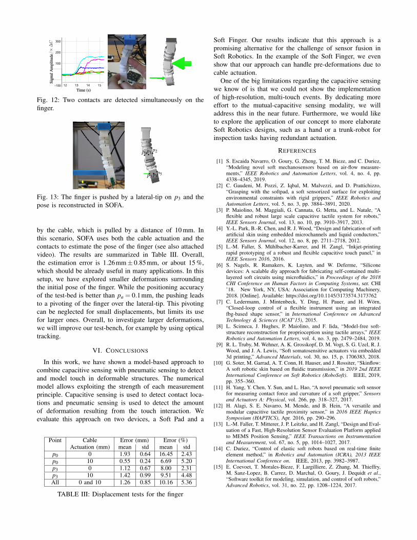
1) Contact Detection: To detect a contact, a simplethreshold is applied to the signal of the capacitive sensors.Then, the constraints corresponding to the contact are en-abled in the model (see Sec. IV-B). The model will find theamount of force applied to all enabled constraints, includingcable actuation, that best explains the measured changesin deformation (volume). The amount of force found for acontact is not determined by the intensity of the capacitivesensor value, but by the optimization method. In Fig. 12,the case of two simultaneous contacts is shown. The signalscorresponding to the enabled contacts is clearly distinct fromthe not activated contacts. It is not necessary to fine-tunethis threshold to get satisfactory behavior for conductiveobjects, such as the human finger. However, detection ofnon-conductive objects remains a challenge for this setup.A mutual-capacitive design could address these use cases.For a more thorough display of possible interactions, pleasesee the attached video.
2) Shape Estimation: To test the accuracy of the shapereconstruction, the lateral-tip shown in Fig. 13 was used. Itis attached to the test-bed displayed in Fig. 8. The fingeris pushed separately on the points p0 and p3 by 5, 10,15 and 20 mm respectively. The estimated displacement ofp0 and p3 in SOFA is compared to the real displacement.This experiment is performed with the finger starting fromits rest position as well as with the finger initially actuated
12 1413 15
0
200
-100
300
Time (s)
Sig
nal A
mpl
itude
100
Fig. 12: Two contacts are detected simultaneously on thefinger.
p0p1 p2
p3 p4p5
Fig. 13: The finger is pushed by a lateral-tip on p3 and thepose is reconstructed in SOFA.
by the cable, which is pulled by a distance of 10 mm. Inthis scenario, SOFA uses both the cable actuation and thecontacts to estimate the pose of the finger (see also attachedvideo). The results are summarized in Table III. Overall,the estimation error is 1.26mm± 0.85mm, or about 15 %,which should be already useful in many applications. In thissetup, we have explored smaller deformations surroundingthe initial pose of the finger. While the positioning accuracyof the test-bed is better than pa = 0.1mm, the pushing leadsto a pivoting of the finger over the lateral-tip. This pivotingcan be neglected for small displacements, but limits its usefor larger ones. Overall, to investigate larger deformations,we will improve our test-bench, for example by using opticaltracking.
VI. CONCLUSIONS
In this work, we have shown a model-based approach tocombine capacitive sensing with pneumatic sensing to detectand model touch in deformable structures. The numericalmodel allows exploiting the strength of each measurementprinciple. Capacitive sensing is used to detect contact loca-tions and pneumatic sensing is used to detect the amountof deformation resulting from the touch interaction. Weevaluate this approach on two devices, a Soft Pad and a
Point Cable Error (mm) Error (%)Actuation (mm) mean std mean std
p0 0 1.93 0.64 16.45 2.43p0 10 0.55 0.24 6.69 5.20p3 0 1.12 0.67 8.00 2.31p3 10 1.42 0.99 9.51 4.48All 0 and 10 1.26 0.85 10.16 5.36
TABLE III: Displacement tests for the finger
Soft Finger. Our results indicate that this approach is apromising alternative for the challenge of sensor fusion inSoft Robotics. In the example of the Soft Finger, we evenshow that our approach can handle pre-deformations due tocable actuation.
One of the big limitations regarding the capacitive sensingwe know of is that we could not show the implementationof high-resolution, multi-touch events. By dedicating moreeffort to the mutual-capacitive sensing modality, we willaddress this in the near future. Furthermore, we would liketo explore the application of our concept to more elaborateSoft Robotics designs, such as a hand or a trunk-robot forinspection tasks having redundant actuation.
REFERENCES
[1] S. Escaida Navarro, O. Goury, G. Zheng, T. M. Bieze, and C. Duriez,“Modeling novel soft mechanosensors based on air-flow measure-ments,” IEEE Robotics and Automation Letters, vol. 4, no. 4, pp.4338–4345, 2019.
[2] C. Gaudeni, M. Pozzi, Z. Iqbal, M. Malvezzi, and D. Prattichizzo,“Grasping with the softpad, a soft sensorized surface for exploitingenvironmental constraints with rigid grippers,” IEEE Robotics andAutomation Letters, vol. 5, no. 3, pp. 3884–3891, 2020.
[3] P. Maiolino, M. Maggiali, G. Cannata, G. Metta, and L. Natale, “Aflexible and robust large scale capacitive tactile system for robots,”IEEE Sensors Journal, vol. 13, no. 10, pp. 3910–3917, 2013.
[4] Y.-L. Park, B.-R. Chen, and R. J. Wood, “Design and fabrication of softartificial skin using embedded microchannels and liquid conductors,”IEEE Sensors Journal, vol. 12, no. 8, pp. 2711–2718, 2012.
[5] L.-M. Faller, S. Muhlbacher-Karrer, and H. Zangl, “Inkjet-printingrapid prototyping of a robust and flexible capacitive touch panel,” inIEEE Sensors 2016, 2016.
[6] S. Nagels, R. Ramakers, K. Luyten, and W. Deferme, “Siliconedevices: A scalable diy approach for fabricating self-contained multi-layered soft circuits using microfluidics,” in Proceedings of the 2018CHI Conference on Human Factors in Computing Systems, ser. CHI’18. New York, NY, USA: Association for Computing Machinery,2018. [Online]. Available: https://doi.org/10.1145/3173574.3173762
[7] C. Ledermann, J. Mintenbeck, Y. Ding, H. Pauer, and H. Worn,“Closed-loop control of a flexible instrument using an integratedfbg-based shape sensor,” in International Conference on AdvancedTechnology & Sciences (ICAT’15), 2015.
[8] L. Scimeca, J. Hughes, P. Maiolino, and F. Iida, “Model-free soft-structure reconstruction for proprioception using tactile arrays,” IEEERobotics and Automation Letters, vol. 4, no. 3, pp. 2479–2484, 2019.
[9] R. L. Truby, M. Wehner, A. K. Grosskopf, D. M. Vogt, S. G. Uzel, R. J.Wood, and J. A. Lewis, “Soft somatosensitive actuators via embedded3d printing,” Advanced Materials, vol. 30, no. 15, p. 1706383, 2018.
[10] G. Soter, M. Garrad, A. T. Conn, H. Hauser, and J. Rossiter, “Skinflow:A soft robotic skin based on fluidic transmission,” in 2019 2nd IEEEInternational Conference on Soft Robotics (RoboSoft). IEEE, 2019,pp. 355–360.
[11] H. Yang, Y. Chen, Y. Sun, and L. Hao, “A novel pneumatic soft sensorfor measuring contact force and curvature of a soft gripper,” Sensorsand Actuators A: Physical, vol. 266, pp. 318–327, 2017.
[12] H. Alagi, S. E. Navarro, M. Mende, and B. Hein, “A versatile andmodular capacitive tactile proximity sensor,” in 2016 IEEE HapticsSymposium (HAPTICS), Apr. 2016, pp. 290–296.
[13] L.-M. Faller, T. Mitterer, J. P. Leitzke, and H. Zangl, “Design and Eval-uation of a Fast, High-Resolution Sensor Evaluation Platform appliedto MEMS Position Sensing,” IEEE Transactions on Instrumentationand Measurement, vol. 67, no. 5, pp. 1014–1027, 2017.
[14] C. Duriez, “Control of elastic soft robots based on real-time finiteelement method,” in Robotics and Automation (ICRA), 2013 IEEEInternational Conference on. IEEE, 2013, pp. 3982–3987.
[15] E. Coevoet, T. Morales-Bieze, F. Largilliere, Z. Zhang, M. Thieffry,M. Sanz-Lopez, B. Carrez, D. Marchal, O. Goury, J. Dequidt et al.,“Software toolkit for modeling, simulation, and control of soft robots,”Advanced Robotics, vol. 31, no. 22, pp. 1208–1224, 2017.