a multifunctional coating for autonomous corrosion …
TRANSCRIPT

A MULTIFUNCTIONAL COATING FOR AUTONOMOUS CORROSION CONTROL
Luz M Calle and Paul E. Hil1lze NASA
Kennedy Space Center, FL 32899
Wenyan Li, Jerry W. Buhrow, and Scon T. Jo lley ASRC Aerospace
Kennedy Space Center, FL 32899
ABSTRACT
[Corrosion is a destructi ve process that o ft en causes failure in metallic components and structures. Protective coatings are the most commonly used method of corrosion control. However, progress ive ly stricter environmental regulati ons have resulted in the ban of many commerciall y available corrosion protecti ve coatings due to the harm ful effects of their solvents or corrosion inhibitors. This work concerns the deve lopment of a multifunctional, smart coating fo r the autonomous control of corrosion. This coating is being developed to have the inherent ability to detect the chemica l changes associated with the onset of corrosion and respond autonomously to control it. The multi-functionality of the coating is based on microencapsulation technology specifically des igned for corrosion control applications. This design has, in additi on to all the advantages of other ex isting microcapsules designs, the corrosion controlled release function that allows the delivery of corrosion indicators and inhibitors on demand only when an where they are needed. Corrosion indicators as well as corros ion inhibitors have been incorporated into the microcapsul es, blended into several paint systems, and tested fo r corrosion detecti on and protection effi cacy.
1. INTRODUCTION
Metals and alloys are present in some shape or form in nearly every facet of our li ves. Nearly a ll metal and metal alloys arc subject to corros ion that eauses them to lose their structural integri ty or other functi onality. It is essential to detect corrosion when it occurs, and preferably at its early stage, so that action can be taken to avoid structure damage or loss of functi on of the metals and their alloys. Because corrosion is mostl y an electrochemical process, pH and other electrochemica l changes are o ft en associated with corrosion, so it is expected that materials that are pH or otherwise electrochemical responsive can be used to detect and control corros ion. The authors developed a smart coating with a controll ed-release system that uses pH-triggered release microcapsules for early detecti on of corros ion and for corros ion protection. The following sections will briefl y describe the relation between pH and corrosion, the design of pH sensiti ve microcapsules and their synthesis, as we ll as selected test results of the smart coating with pH sensitive microcapsules fo r corros ion indicati on and inhibition.
1.1 Corrosion and pH
Th is paper is declared a work of the U.S. Government and is not subject to copyright protection in the United States .

[Corrosion is largely an electrochemical phenomenon, because, in most cases, it involves the transfer of electrons between a metal surface and an aqueous electrolyte solution. For instance, when iron corrodes in near neutral environments, the typical electrochemical reactions are:
Cathodic reaction: 0 , + 2H ,0 + 4e ~ 40H
Anodic reaction:
P Of0U'5 CaJl 0 ,. H, Q
fi gure 1. The electrochemical cell set up between anodic and cathodic sites on an iron surface undergoing pitting corrosion.
In the case of localized corrosion, such as pitting corros ion, the anodi c reaction happens in a confi ned area, the metal ions produced are precipitated as solid corrosion products, such as iron(lI) ox ide, Fe(OH)2, (often further oxidized to iron(lll ) ox ide, Fe(OH)3), which covers the mouth of the pi t.
2Fe'· + 2H ,0 + 0 , + 4e~ ~ 2Fe(OH ), - - -4Fe(OH ), + 2H ,0+ 0 , ~ 3Fe(OH )3
This covering traps the solution in the pit and all ows the bu ildup of hydronium ions, H-, through a hydrolysis reaction:
Fe'· + 2H,0 ~ 2Fe(OH ), + 2H ·
Then, chloride, cr, or other damaging negative ions diffuse into the pit to maintain charge neutrali ty. Consequentl y, the solution inside the pit becomes highly acidic. The overall effect is that, while localized corrosion happens, the anode area often has an acidic pH and the cathode has an alkaline pH .'
2

Besides pitting, crevice corrosion and diss imilar metal corrosion result in pH changes as the simple demonstration in Figure 2 shows. A universal pH indicator was used to show the pH changes that occur during corrosion of a metal, such as steel. In this demonstration, most of the steel was exposed to water whil e a strip in the midd le was wrapped in copper tape. The color change of the pH indicator shows that the exposed steel tends to be acidic (yell ow color) whi le the strip wrapped in the copper tape tends to be basic (purple color) due to the oxygen reduction reacti on and the release of the hydroxide ion, OH' .
j Addle
:J SIIBhtfy AcIdic:: Ohour 5 hours
- Neutnol
:=J SIIBhtfy Basic
- Basic 1 hour 3 days
Figure 2. pH Changes associated with corrosion.
pH and other electroc hemical changes are often assoc iated with corrosion, so it is expected that materials that are pH or otherwise electrochemica l responsive can be used to detect and control corrosion. Various pH and electrochemical responsive materials and their potential applications in smart coatings for corrosion control can be found in our prev ious review2 Self healing coatings is another new development in material design that is important to corrosion controI3
•4
•5
lnsert text]
1.2 pH sensitive Microcapsules
The authors developed a controlled-release system that combines the advantages of corrosion sensing and corrosion protection by using pH-triggered release microcapsules for early corrosion detection and corrosion protection2
.6
.7 The key component of this technology is a pH sensitive
microcapsule with a wall designed to break down and release the encapsulated contents in response to the pH condition of the cathodic site of locali zed corrosion (as shown the fi gure below).
3

... , ..... -.-.. pH
-~.-~ -*I
". ..... at .. " .... .. -_ ..... _pH _F .-... .. _ tljdi: I) iii r..-..
pH_",-__ io
....... tan .. 'i ... '4 .. lnilrblllc ...... .
Figure 3. The key component ofthe smart coating system: pH sensitive microcapsules.
The chemistry of the pH sensiti ve microcapsul es is base-catalyzed ester hydrolys is. The polymeric walls of the microcapsules include a cross-linking agent that has one or more ester and mercapto groups. A typica l cross-linker is pentaerythritol tetraki s (3 -mercaptopropionate) (PTT), a tetra-functional molecul e wbose structurc is shown below.
Figure 4. Structure of pentaerythritot tctrakis (3-mercaptopropionate) (PTT).
Since this cross-linker is not a good film fo rmer, other prepolymers or monomers are needed to provide the structural integri ty of the microcapsul e wall. Examples of the film-forming monomers and pre-polymers include urea fo rmaldehyde and melamine formaldehyde monomers and prepolymers. A generali zed structure of a urealfomlaldehyde/PTT condensati on polymer is given in Figure 5.
4

Figure 5. Generalizcd urea/formaldehydc/PTT structurc, where R represents a continuation of the condensation polymcr.
The mercapto functionality is an excellent participant in forming the microcapsule wall s. The proton on the thiol moiety is quite acidic, allowing it to function as an excellent active hydrogen group. The pKa value of alkyl mercaptans falls generall y in the 10-11 range which is significantly lower than water ( 15 .7) and alcohols (16_1 8)8 The 3-mercaptopropionate version proved to be more useful than other commercially available mercaptoesters based on mercaptoethyl ester chemistry. Mercaptoethyl versions reacted more quickl/ and cross- linked to a greater degree than the mercaptopropyl chemistry, which cou ld result in a polymer condensation rate too fast for the optimized encapsul ation conditions when in-siru polymerization is used. The hydroxyalkyl pol yo I esters were also considered as possible candidates for use as hydrolysable crosslinkers, but their preparation prcscnts difficulties due to the self condcnsation side reaction.
Capsule wall breakdown under basic conditions can be observed visuall y. Figure 6 shows such breakdown occurring in response to exposure to a small amount of water containing sodium hydroxide, NaOH, (pH of 12). Soon after the NaOH solution was added, the so lution starts to penetrate the microcapsul e wall, as indicated by the color change inside the microcapsules (Frames b-d). In frame e, the microcapsul e begins to slowly rel ease its contents (as evidenced by the small droplet that begins to form on the bottom left quadrant of the frame). The content continues to be released until (as seen on frame i), it di ss ipates into the solution. The microcapsule wall eventually collapses as shown in frames j through n.
5

Figure 6. Microcapsule breakdown in bas ic solution.
1.3 Smart Coating Based on pH Sensitive Microcapsules
Microcapsulation is a versatile approach because it can be used to encapsulate an unlimited number of materials, in both solid and liquid phase, and even in the gas phase when entrapped in aerogel. It is possible to incorporate microcapsules into composites or coatings. For corrosion applications, various compounds, such as corrosion ind icators, inhibitors, self-healing agents, and dyes can he encapsulated. These microcapsules can be incorporated into vari ous coating systems for corrosion detection, protecti on and self-repair of mechanical coating damage (Figure 7). The versatili ty of the design is of special interest in corros ion inhibition applications. Almost all corrosion inhibitors are chemically active reagents. Very often, the reacti vity that makes them effective corrosion inh ibitors also causes them to be environmentally un friendly, such as in the case of chromates. Because of thi s, research fo r new and environmentally friendly corrosion inhibitors is an on-going effort in the corrosion protection industry. After a new inhibitor is developed, it usually takes a long time to incorporate it into a paint formulation. A smart coating that includes encapsulated inhibitors and releases them on demand when corrosion starts, can shorten this long reformulation process fo r new inhibitors by simply changing the core content of the microcapsul es.
The pH-controlled release microcapsul e design has, in addition to all the advantages of the regul ar microcapsule design, the true controlled-release func tion for corros ion applications. Regular microcapsules release their contents when they are mechanically broken. pH sensiti ve microcapsules release their contents when corrosion occurs. Mechan ical damage in a coating is one of the important causes for corros ion of the base metal. However, it is not the only one. Many fo mls of defects in coatings, such as air bubbles, uneven thi ckness, permeation, porosi ty or edge effects, will result in poor corrosion protection of the coating and allow corros ion to occur. pH sensiti ve microcapsul es will release their content fo r corrosion detection or protecti on regardless of the corrosion cause.
6

- ------ - - --
1 ~!on Indlcatgnl
Ruplunld Mic:rc>apOUle: -Indl __ on
. pl'Cllt8cta metal from COI"T'OIIIion
. ,....,,. damaged .,..
~h.nic.1 damage ca~" c 'p&ul. to
ruphJrfl
l' Corrosion
c: au." c:apaule
'OT"M~$
Figure 7. Smart coating with pH sensitive microcapsules for corrosion detection and protection applications.
1.4 Encapsulation Process
1.4.1 Encapsulation Methods
pH sensitive microcapsules are the key component o f the smart coatings. Severa l methods such as spray drying, emulsion polymerization, interfac ia l polymerization, as well as in-situ polymerization have been used to synthesize pH sensitive microcapsules. Interfac ial polymeri zati on is illustrated below as an example. There are two main steps involved in the interfacial polymerizati on process: microemulsion fo nnation and microcapsule wall fonnation. This technique can be used to fo rm both oil (or hydrophobic) core and water (or hydrophilic) core microcapsules. Figure 8 shows a schemati c representation of the steps involved in fonning oil core microcapsules: the microemulsion is fo nned by addi ng the oil phase (with prepolymer, shown in yellow) to the water phase (with surfactant, shown in blue) and mi xing; the last step is the fonnation of the microcapsule wa ll (shown in green) by interfacial polymerization. Figure 9 shows a schematic representati on of the steps involved in fo nning water core microcapsules: in thi s case, the microemulsion is fo mled by adding water (shown in blue) to the oil (with prepolymer and the surfactant, shown in yellow) fo ll owed by mixing; the last step is the formation o f the mi crocapsule wa ll (shown in green) by interfac ial polymerization.
7

surfac1a11 prepcr,mer
water
, t
Addition of oi l and prepotymer
, t mixing
Caps •• with polymer wall
00 o
000
, t
potymerization
Figure 8. Schematic representation of the steps involved in the interfacial polymerization of an oil-in-water microemulsion for making oil core microcapsules. Oil is shown in yellow and water in blue.
prepotymer surfactant
oil oil
, t
Addition of water
• •• • , t
Capsule with po/ymerwall
, t
mixing potymerization
Figure 9. Schematic representation of the steps involved in the interfacial polymerization of a water-in-oil microemulsion to synthesize water core microcapsules. Oil is shown in yellow and water in blue.
The two illustrati on above involve the use of oil , or hydrophobic so lvent soluble wall fo nning prepo lymer. A similar process can be deve loped to use water soluble wa ll fo nn ing materials by
8

dissolving the wall forming prepolymer in the water phase and the catalyst in the oil phase. The reaction at the interface will form the capsul e.
In situ polymerization is also used to form pH sensitive microcapsules . The distinguishing characteristic between interfacial polymeri zation and in s itu polymerization is that the polymerization reaction occurs in the continuous phase and the polymer is formed through the reaction deposits at the interface to form the capsul e wall.
Spray drying involves dispersing the wall fo rming precursor and substance to be encapsulated (the core material) into a continuous phase (water for instance), spraying the mixture into a mist and irno a hot gas fl ow; the liquid droplets arc dried into solid particles. In the process, the core material is encapsulated inside the wall materials.
Interfac ial polymerization and in-situ polymerization are the main approaches used by the authors for microcapsule synthesis. Interfacial polymeri zation is used to synthesize oil-core and water-core microcapsules with corrosion indicators, corros ion inhibitors, and self healing agents as acti ve core contents. In s itu polymeri zation is also used to synthesize microcapsules with corrosion indicators and self healing agents mainly into oil-core microcapsules where water is used as the continuous phase. Spray drying has been used to synthesize solid core microcapsules and as a use ful method for dry ing microcapsul es into a free fl owing powder form without forming clusters.
1.4.2 Microcapsule Synthesis
Di fferent acti ve core contents have been encapsulated, including corrosion indicators, corrosion inhibitors, dye, and se lf healing agents. Both water core microcapsules and oil core microcapsules were synthesized using the methods described above.
To tailor these processes for encapsul ating corrosion inhibitors and indicators, various indicators and inhibitors were selected and tested for their indicating and inhibiting effici ency respectively . The so lubili ty and dispersibility of the acti ve compounds were surveyed or tested to find a suitable method for their encapsulation.
An acti ve compound that can be di sso lved or d ispersed in a hydrophobic solvent, such as o il , can be encapsul ated into oil core microcapsules. Normally, oil core microcapsules are used for encapsulating oil soluble materials but not water soluble materials, such as salts or polar molecules. However, these materials can still be encapsulated by di ssolving them first into a polar co-solvent and adding the resultant solution to the oil phase. Alternatively, a surfactant can be added to the oil phase. This will dissolve or disperse the polar or water soluble reagents into the oil phase. The oil-in-water emulsion can then be formed and the interfacial reaction can be used to encapsulate these reagents into tbe oil core of the microcapsules (Figure 10).
Similarly, if a compound can be di ssolved or di spersed in water, with or without the aid of a cosolvent, or a surfactant, it is possible to encapsulate it into water core microcapsules . For example, phenolphthalein does not di ssolve in water, but ethanol can be used as a co-solvent to di ssolve moderate amount of the indicator in water making it possible to encapsulate it into water core microcapsul es (Figure 11 ).
9

Figure 10. Oil core microcapsules with a pH indicator as core content.
Figure II. SEM images of the water core microcapsules with phenolphthalein
Various compounds of interest for corrosion control applications have been encapsulated into oil core microcapsules. These compounds include: corrosion indicators such as phenolphthalein , phenol red, and fluorescein ; corrosion inhibitors such as cerium(IlI) ch loride, CeCil; dyes such as Rhodamine B; healing agents such as epoxy and polysil oxane; and various solvents, such as chlorobenzene, which can be used as a healing agent. Some examples of these oil core microcapsules are shown in Figure 12.
10

Figure 12. Oil Core Microcapsules in free flowin g powder form . The core contents of these microcapsules are Rhodamine B (on the left ), Phenolphtha lein (in the middle), and a universal pH indicator (on the right).
Various corrosion inhibilors and indicators have been encapsulated into water core microcapsules, such as corrosion indicator phenolphthalein, corrosion inhibitor sodium molybdate, Na2Mo04, cerium nitrate, Ce(N03h, sodium phosphate, NaH2P04, calcium metaborate, and phenol phosphoric acid. Some examples of these oi l core microcapsules are shown in Figure 13.
Figu re 13. SEM images of microcapsules with different inhibitor core contents at different concentrations. From left to right: low, medium, and high inhibitor concentrations. From top to bottom: Ce(N03h, Na2MoO,,,
and Na H2PO" inhibitors.
After a microcapsule fom1Ula is developed, an optimization process usually follows to obtain microcapsules of desired properties, such as a suitable size for its application. The capsule size can be controlled by adjusti ng the emulsion formula or by varying the mixing speed of the mixer
II

or the homogenizer during the emulsion formation. These methods can be used to obtain microcapsules of a desired size within a narrow range of di stribut ion. Sizes from 200 nm to 200 micron can be obtained, with a typical size from about I to 5 microns. Oil core microcapsules of vari ous sizes are shown in Figure 14.
Figure 14. Oil core microcapsules of different sizes.
The SEM images in Figure 15 show capsules of spherica l shape with less than I ~m in di ameter size. The capsule wall thickness is about 50-100 nm as shown in the SEM images of the microcapsules obtained using a transmiss ion electron detector (Figure 16).
Figure 15. SEM Images of the water core microcapsule.

Figure 16. SEM images of a water core microcapsule obtained by using a transmission electron detector.
Figure 17 shows an example of o il core microcapsules with a size range from 10 to 20 microns in which epoxy was encapsulated through the in situ polymerization reaction in oil-in-water emulsion for self healing applications. The same fi gure also shows the relatively smooth wall surface of the microcapsules. The wa ll thickness of these microcapsules was measured by incorporating the microcapsules into a thin film and observ ing a cross section of the film by SEM ( Figure 18). This capsule wall appears, on average, to be about 300 nm to I micron thick.
13

Figure 17. SEM images of oil core microcapsules with epoxy self healing agent.
Figure 18. SEM images of the cross section of oil core microcapsules in a polymer fi lm.
1.4.3 Sub sub-heading
2. EXPERIMENTATION AND RESULTS
Microcapsules have been incorporated into different commercially ava ilable coat ings in order to test their corros ion indication and inhibition functions. Preliminary results of these tests are presented below.
2.1 Corrosion Indication Tests
Corrosion indication is one of the functions of the smart coating for corrosion detection, control, and self healing. This function can be incorporated into the coating by encapsulating a corrosion indicator in to pH sensitive microcapsules or particles. Figure 19 shows the results from the salt immersion test of steel panels coated with a clear urethane coating containing 10% of microcapsules with corrosion indicator. The panels were scribed and observed fo r visual changes over time. It was observed that the indicator signaled the onset of corrosion in the scribe about I minute after immersion which is considerably earlier than the 2 hours for the appearance of the typical color of rust.
14

Before immersion initial 30 sec 1 min 2 min 3 min 5 min
15

Figure 19. Corrosion indication test reusu lts.
16

17

in addition to early corrosion detection, another potential application of the smart coating is to detect hidden corrosion. A conceptual illustration of how these coatings can be used to detect hidden corrosion is shown in Figure 20.
~ :.'
Figure 20. Conceptual illustration of hidden corrosion indication in structural bolts.
An experiment was designed to test the ability of the encapsulated indicator to detect hidden corrosion when incorporated into a coating system. Several coating systems (Table No) were prepared in order to find a coating system that would indicate crevice corrosion as can be expected to occur in the nut and bolt set up shown in figures No. As it can be seen in Figure No, the epoxy/urethane coating system showed the ability of the coating to indicate hidden corrosion as evidenced by the appearance of the purple color.
S stem #
2
3
4
5
Sand blasted nut and bolt to bare carbon steel. The ends of the nut and bolt were coated with Cathacoat 304V® inorganic zinc coating. The entire nut and bolt was coated with Diamond Clad 3-part urethane® containing 10% phenolphthalein
articles. Sand blasted nut and bolt to bare carbon steel. The ends of the nut and bolt were coated with Cathacoat 304 V® inorganic zinc coating. The entire nut and bolt was coated with Macropoxy 2-part epoxy® and then top coated with Diamond Clad 3-part urethane® containin 10% henol hthalein articles.
18

6 Zinc galvanized nut and bolt where the ends of the nut and bolt were coated with Macropoxy 2-part epoxy® and top coated with Diamond Clad 3-part urethane® containing 10% phenolphthale in particles.
Initial Pictures
(
237 hours salt fog
19

20

----- ----------
605 hours salt fog
21

---------------------
Figure 21. Selected pictures that show hidden corrosion indication.
22
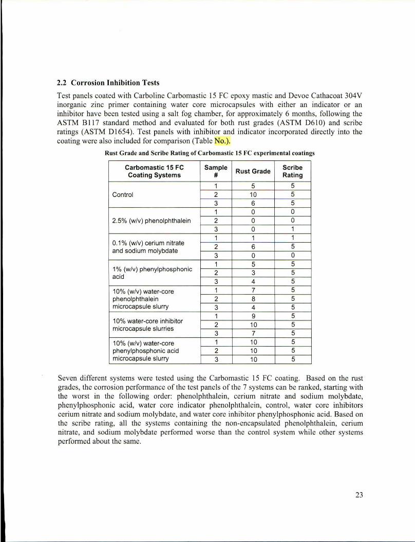
2.2 Corrosion Inhibition Tests
Test panels coated with Carboline Carbomastic 15 FC epoxy mastic and Devoe Cathacoat 304V inorganic zinc primer containing water core microcapsules with either an indicator or an inhibitor have been tested using a salt fog chamber, for approximately 6 months, fo llowing the ASTM B 11 7 standard method and evaluated for both rust grades (ASTM D6 10) and scribe ratings (ASTM D 1654). Test panels with inhibitor and indicator incorporated di rectly into the coating were also included for compari son (Table No.).
Rust Grade and Scribe Rating of Carbo mastic IS Fe experimental coatings
Carbomastic 15 FC Sample Rust Grade
Scribe Coat ing Systems # Rating
1 5 5 Control 2 10 5
3 6 5 1 0 0
2.5% (w/v ) phenolphtha lein 2 0 0 3 0 1
1 1 1 0.1 % (w/v) cerium nitrate
2 6 5 and sodium molybdate
3 0 0 1 5 5
1 % (w/v) phenylphosphonic 2 3 5
acid 3 4 5
10% (w/v) water-core 1 7 5 phenolphthalein 2 8 5 microcapsule slurry 3 4 5
1 9 5 10% water-core inhibitor
2 10 5 microcapsule slurries
3 7 5
10% (w/v) water-core 1 10 5 phenylphosphonic acid 2 10 5 microcapsule slurry 3 10 5
Seven different systems were tested using the Carbomastic 15 Fe coating. Based on the rust grades, the corrosion performance of the test panels of the 7 systems can be ranked, starting with the worst in the following order: phenolphthalein, cerium nitrate and sodium molybdate, phenylphosphonic acid, water core indicator phenolphthalein , control, water core inhibitors cerium nitrate and sodium molybdate, and water core inhibitor phenylphosphonic acid. Based on the scribe rating, all the systems containing the non-encapsulated phenolphthalein, cerium nitrate, and sodium molybdate performed worse than the control system whi le other systems performed about the same.
23

24

25

26

RuSI Grade for Calhacoal 304V Zn primer for sail fog samples
Cathacoat 304V Coating Sample # Rust Grade
Systems
1 1 Control 2 2
3 3 1 5
2.5% (w/v) phenolphlhalein 2 5 3 4 1 3
0.1 % (w/v) cerium nitrale and 2 3
sodium molybdate 3 3
10% (w/v) water-core 1 4 phenolphthalein microcapsule 2 6 slurry 3 7
1 6 10% water-core inh ibitor
2 7 microcapsule slurries
3 7
Five different systems were tested using the Cathacoat 304V Zn primer. The fol losing corrosion performance ranking, staning with the worst, was obtained by comparing the rust grades for the test panel s of the 5 systems: control , cerium nitrate and sodium molybdate, phenylphosphonic acid, phenolphthalein, water core indicator phenolphthalein, water core inhibitors cerium nitrate and sodium molybdate.
27

28

---------------- - ------------
Figure 22. Pictures of Devoe 304 Zn primer panels after 15 days in salt fog testing
3. SUMMARY
4. REFERENCES
I. I. F. J. Maile, T. Schauer, and C. D. Eisenbach, Evaluation of corrosion and protection of coated metals with local ion concentration technique (LICT), Progress in Organic Coatings 38, III (2000).
2. I. W. Li and L. M. Calle, pH and Electrochemical Responsive Materials for Corrosion Control Applications (Invited), NACE Corrosion 2008, New Orleans, LA, March 2008.
3. I. M. R. Kessler, Self-healing: a new paradigm in material design, Proc. [MechE Vol. 221 Part G: J. Aerospace Engineering, page 479-495 (2007)
4. I. Magnus Andersson, Gerald O. Wilson, Scott R. White, Evaluation of Self-Healing Polymer Chemistries for Application in Anti-Corrosion Coatings, American Coatings Conference 2008 at Charlotte, NC (June 2-4, 2008).
5. I. Soo Hyoun Cho, PhD Thesis "Polydimethylsiloxane-Based Self healing Composite and Coating materials", University of lIIinois at Urbana-Champaign, Urbana IL (2006).
6. I. W. Li and L. M. Calle, Controlled Release Microcapsules for Smart Coatings, NACE Corrosion 2007, Paper 07228, Nashville, TN, March 2007
7. I. W. Li and L. M. Calle, A smart coating for the Early Detection and Inhibition of Corrosion, Proceeding of the Smart Coatings 2007, p.191 , Orlando, Florida, February 2007
8. I. Jerry March, Advanced Organic Chemistry, second edition (1977) (R. H. Summersgill and A. T. Vinnicombe, Eds) McGraw-Hili Book Company.
9. I. A. E. Rydholm, K. S. Anseth, and C. N. Bowman, Acta Biomater, 3, 449-455 (2007)
10. [Insert reference I]
II. [Insert reference 2]
12. [Insert reference 3]
13. [Insert reference 4]
14. [Insert reference 5]
IS. [Insert reference 6]
16. [Insert reference 7]
17. [Insert reference 8]
18. [Insert reference 9]
19. [Insert reference 10]
'. F. J. Maile, T. Schauer, and C. D. Eisenbach, Evaluation of corrosion and protection of coated metals with local ion concentration technique (L1CT), Progress in Organic Coatings 38, III (2000). 2. W. Li and L. M. Calle, pH and Electrochemical Responsive Materials for Corrosion Control Applications (Invited), NACE Corrosion 2008, New Orleans, LA, March 2008 .
29

3. M. R. Kessler, Self-healing: a new paradigm in material design, Proc. IMechE Vol. 221 Pan G: J. Aerospace Engineering, page 479-495 (2007) 4. Magnus Andersson, Gerald O. Wilson, Scott R. White, Evaluation of Self-Healing Polymer Chemistries for Application in Anti-Corrosion Coat ings, American Coatings Conference 2008 at Charlotte, NC (J une 2-4, 2008). 5. Soo Hyoun Cho, PhD Thcsis "Polydimcthylsi loxanc-Bascd Self healing Composite and Coating materials" , University of Illinois at Urbana-Champaign, Urbana IL (2006). 6. W. Li and L. M. Calle, Controlled Release Microcapsules for Sman Coatings, NACE Corrosion 2007, Paper 07228, Nashville, TN, March 2007 7. W. Li and L. M. Calle, A sman coating for the Early Detection and Inhibition of Corrosion, Proceeding of the Sman Coatings 2007 , p.191, Orlando, Florida, February 2007 8. Jerry March, Advanced Organic Chemistry, second ed ition (1977) (R. H. Summersgill and A. T. Vinnicombe, Eds) McGraw-Hili Book Company. 9. A. E. RydhoLm, K. S. Anseth, and C. N. Bowman, Acta Biomater, 3, 449-455 (2007)
•
30