a multiphysics thermal-fluid analysis of a non-nuclear ... · source of acquisition nqa marshall...
TRANSCRIPT
Source of Acquisition NQA Marshall Space Flight Center
A Draft Paper for STAIF-2006, Feb. 12-16,2006, Albuqerque, New Mexico. Multiphysics Thermal-Fluid Analysis of a Non-Nuclear
Tester for Hot-Hydrogen Materials Development
Ten-See Wang, John Foote, and Ron Litchford
NASA Marshall Space Flight Center, Huntsville, Alabama, 35812
Abstract. The objective of this effort is to analyze the thermal field of a non-nuclear tester, as a first step towards developing efficient and accurate multiphysics, thermo-fluid computational methodology to predict environments for hypothetical solid-core, nuclear thermal engine thrust chamber design and analysis. The computational methodology is based on a multidimensional, finite- volume, turbulent, chemically reacting, radiating, unstructured-grid, and pressure-based formulation. The multiphysics invoked in this study include hydrogen dissociation kinetics and thermodynamics, turbulent flow, convective, radiative and conjugate heat transfers.
Keywords: Multiphysics, computational fluid dynamics, conjugate heat transfer, nuclear thermal engine.
PACS: 47.1 1 .+j; Computational methods in fluid dynamics.
INTRODUCTION
Nuclear thermal propulsion (NTP) may open up the solar system to far broader and faster exploration than is now possible with chemical propulsion. The feasibility of NTF’ systems was established by extensive testing in the RoverMERVA programs and the technical merits of NTP have been identified in numerous studies (Koenig, 1986). In a NTP system, the propellant is heated by a nuclear reactor instead of combustion. The best NTP propellant is hydrogen with which high exhaust speed can be achieved with its low molecular weight, resulting in high thrust per unit mass of propellant consumed. Under the operating temperature inside a nuclear reactor, often at 2,500-3,OOO deg. K, the heated hydrogen further dissociates into atomic hydrogen - at a formula weight only half that of molecular hydrogen, indicating an even greater thrust may be realized. The heat transfer efficiency and degree of hydrogen dissociation are therefore two very important performance factors for NTP. On the other hand, the need to push fuel element temperatures to extremes in order to maximize performance also intensifies hydrogen induced corrosion rates, which are known to increase in direct proportion to reactor operating temperature. In order to develop candidate high temperature fuel materials that would be compatible with the hot hydrogen environment of a high performance solid core NTP engine, a non-nuclear test effort entitled “Hot Hydrogen Materials and Component Development” is underway at NASA’s Marshall Space Flight Center (MSFC). In the mean time, this study is performed under a task entitled “Multiphysics Thrust Chamber Modeling” to develop a computational methodology capable of predicting the thermal-fluid environment in a nuclear thermal engine thrust chamber. This is important because one of the most significant improvements in engineering capability since the RoverhTERVA program is the ability to provide accurate and detailed models of the engineering environment prior to hardware fabrication and test. After the cancellation of the RoverMERVA program, project personnel indicated that use of such computational engineering would be instrumental to future developments to understand and prevent the types of material failures that were identified during concept testing. A thermal-fluid computational tool based on an Unstructured-grid Navier-Stokes Internal-external flow Code (UNIC), that was anchored with Space Shuttle Main Engine thruster performance and heat transfer (Wang, 2004), is therefore being enhanced to address the kind of multiphysics encountered in a NTP thruster. In this study, as a first step, the UNIC computational methodology is benchmarked with the thermal-fluid data obtained from the afore-mentioned “Hot Hydrogen Materials and Component Development” effort. A design analysis of the test fixture for that effort is also presented to demonstrate the UNIC capability in design and analysis of NTP thrust chambers.
COMPUTATIONAL METHODOLOGY
The time-varying transport equations of continuity, species continuity, momentum, total enthalpy, turbulent kinetic energy, and turbulent kinetic energy dissipation can be written as:
https://ntrs.nasa.gov/search.jsp?R=20060007803 2018-09-06T19:05:17+00:00Z
"p+-(ou d j)' 0 at a x j
-+a(p jaj )=q a at ax j
A predictor and corrector solution algorithm was employed to provide coupling of the fluid governing equations. A second-order central-difference scheme was employed to discretize the diffusion fluxes and source terms of the governing equations. For the convective terms, a second-order upwind total variation diminishing difference scheme was used in this effort. To enhance the temporal accuracy, a second-order backward difference scheme was employed to discretize the temporal terms. A point-implicit (operator splitting) method was employed to solve the chemistry system. An extended k-E turbulence model (Chen, 1987) was used to describe the turbulence.
The convective heat transfer follows the modified Newtonian law
Q, =(pu,/T+)(h, - h p - R ( u g / 2 ) )
The radiative heat transfer is analyzed by solving the radiative transfer equation
(Q . V)Z( r , Q) = -KI( r , SL) + KZb ( r )
Discrete ordinate method was used to solve the radiative transfer equation. The radiative heat flux is given by the integration of the wall leaving radiative intensities
Details of the numerical algorithm can be found in (Wang, 2003 and 2004).
DESIGN ANALYSIS
Three design analyses were performed to demonstrate capability of UNIC computational methodology in helping the design of the text fixture for a non-nuclear hot-hydrogen materials development. Multiphysics invoked in this simplified analysis include turbulence, hydrogen dissociation and thermodynamics, convective heat transfer, and surface radiation. As shown in Fig.1, the sample for material testing is placed inside a water-cooled chamber where it is subjected to the external heating of a hot-hydrogen jet, which is heated by a 1-MW arc-heater. The goals of this design analysis are to ensure the computed total chamber wall heat flux lower than a pre-determined 5 . 0 ~ 1 0 ~ Watts/m2, and to minimize the heat loss of the hot-hydrogen jet such that nuclear reactor operating temperature can be achieved when the jet reaches

the sample.
Run matrix
Figure 1 shows three design configurations for the test fixture: baseline, baseline with funnel, and baseline with shield. The computational domain includes part of the arc- heater containing a straight inlet pipe and an anode section, the copper chamber wall, and a graphite insert. The anode section of the arc heater and the beginning part of the chamber wall form a divergent section, while the rear part of the chamber wall and the graphite insert form a convergent section. The latter part of the graphite insert is a straight pipe that serves as the flow exit. The sample is placed near the end of the chamber. The funnel configuration has a funnel placed in front of the sample in order to reduce the energy dissipation of the hot-hydrogen flow. The shield configuration has a shield that not only prevents the overheating of the chamber wall, but also serves as a radiation shield for maintaining the surface temperature of the heated sample.
The run matrix is shown in Table I where four cases were run for the baseline configuration to show the effects of hydrogen dissociation and surface radiation. A simple one- step hydrogen dissociation reaction was used for the finite- rate chemistry (Wang, 2004). Two cases were run for each of the funnel and shield configurations to study the effects of surface radiation. Note that the shield is supported by a
Baseline case
copper chamber wall 0 9 F --@?Qh,f@ - -, .. x.!QSeq 6.
1- _/ --
,’ hot H2 inflow - @
Baseline with funnel
Baseline with shield configuration 3
.
FIGURE 1. Three design configurations for the hot- hydrogen test fixture.
360 deg. Flange and it is closed off at the intersection of the anode section and the chamber wall.
Table I. Run matrix
Boundary Conditions
No-slip condition was applied to the solid walls. Fixed mass flow rate boundary condition was used at the inlet, and mass conservation boundary condition was used at the exit. For a conservative calculation of the chamber wall heat flux, a fixed temperature of 400 deg. K was estimated for the chamber wall and the hot-hydrogen temperature was set at 3500 deg. K. The wall temperature of the upper shield facing the chamber wall was estimated to be 2600 deg. K from a separate 1-D heat transfer calculation. Adiabatic condition was applied to walls of sample, funnel, lower shield and flanges, and graphite insert. The hydrogen inlet mass flow rate was 10 g/s and the chamber pressure was 35 atm. An emissivity of 0.6 was applied to the copper chamber wall, whereas an emissivity of 0.4 was applied to the shield. The emissivity for the rest of the solid walls was set at 0.9. The inlet boundary was considered as a radiating wall to approximate the radiation from the Arc heater section. A series of pre-calculations were performed on the baseline case to iterate the inlet temperature and species concentrations such that the inlet species concentrations correspond to a
temperature of 3500 deg. K.
Preliminary results
I
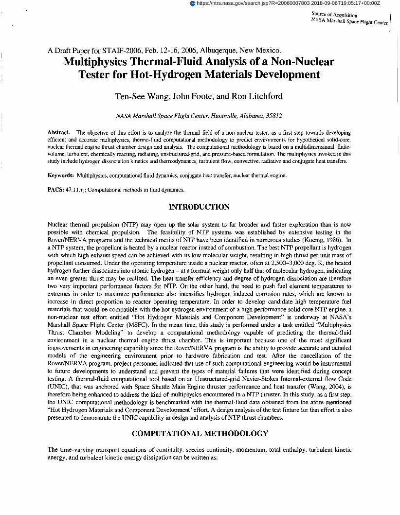
Figure 2 shows the computed temperature, H mass fraction contours and streamlines for the baseline case (with radiation and finite-rate chemistry). Temperature contours show the energy dissipation of the hot hydrogen jet, due to the heat exchange between the hot jet and the cooled chamber wall. As a result, H recombines to become H2, in the colder temperature region. The streamline plot shows an expanding jet flowing around the sample, picking up the speed later in the convergent section. A large recirculation zone appears in the divergent section of the chamber, while a small recirculation region forms behind the sample holder; both of which are affected by the turbulence. Note that the pressure and Mach number contours are fairly uniform inside the chamber (not shown), until they reach the exit pipe.
drogen dissociation and H recombination in the temperature calculation. With surface radiation, the central sample
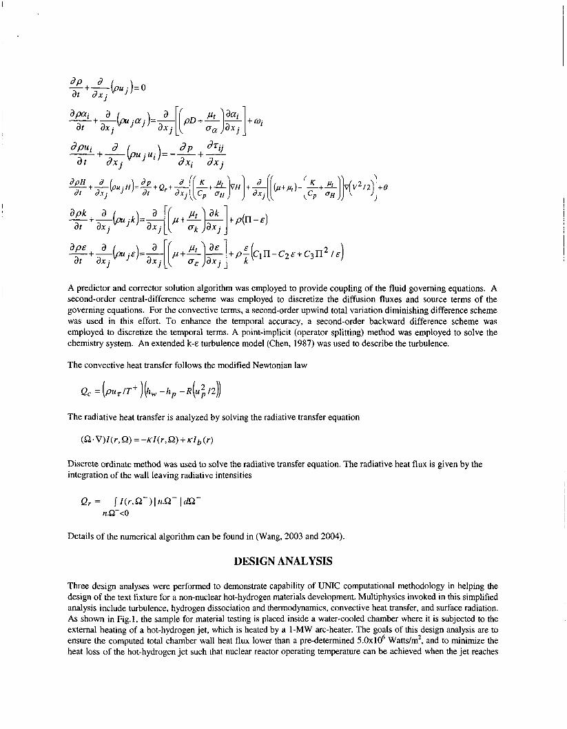
Figure 3 shows the computed centerline temperature profiles from inlet to the sample front face for the baseline configuration. The centerline line temperature is able to maintain a nearly constant value until the energy dissipation starts to take effect and it drops rapidly until reaching the sample front surface. Without radiation, the central surface temperatures for frozen and finite-rate chemistry are 2954.1 and 3 170.8 deg. K, respectively. Since the H is unable to recombine during the frozen chemistry calculation at low temperatures, the unphysical species composition results in incorrect thermodynamic property distribution, driving the local
I I
I I
FIGURE 2. Computed temperature, H mass fraction contours and streamlines for baseline case.
3400 - 3300 - 3200 - 3100 -
z -' 3000 2900
2800 - 2700 -
l i l d frc no radiation tlld frcr with radiation Hld fzc no radiation lf ld fzcr with radiation
+ .--......
2600 kbaseline
\
'. \. \.
sample stagn pt
\ 250Ob.dp ' ' ' ' -0 I 15 ' ' ' ' -0 I 1 ' ' ' ' -0 I 05 ' ' '
x. m ' " 4 2 4 1 0 0 1
x, m
UGURE 4. Computed total, convective, and adiative heat fluxes s:: chambe: ws!! fcr base!ine ase.
surface temperature drops further due to surface energy exchange with the colder chamber wall, resulting in central surface temperatures for frozen and finite-rate chemistry at 2805.6 and 3052.8 deg. K, respectively. Table I1 gives a summary of the central surface temperature for the four parametric cases. The finite-rate chemistry and radiation combination is obviously the right solution for the baseline case. However, the approximately 450 deg. K temperature
drop from inlet indicates energy dissipation is too fast. In addition, the 118.0 deg. K temperature drop with and without radiation indicates a radiation shield may be in order.
chemis the computed total, convective, and radiative heat 2954.1 Frozen fluxes along the chamber wall, between anode and graphite 2805.6 Frozen sections. The radiative heat flux is at least one order-of-magnitude 3170.8 Fini te-rate lower than the convective heat flux, because neither H2 nor H is 3052.8 Finite-rate participatin; medium and only surface radiations from hotter
surfaces to colder chamber wall are contributing. The average tc flux about lx107 Wattdm2 at the hot hydrogen flow impingement point on the chamber, indicating the baseline configuration may have overheating issue as well.
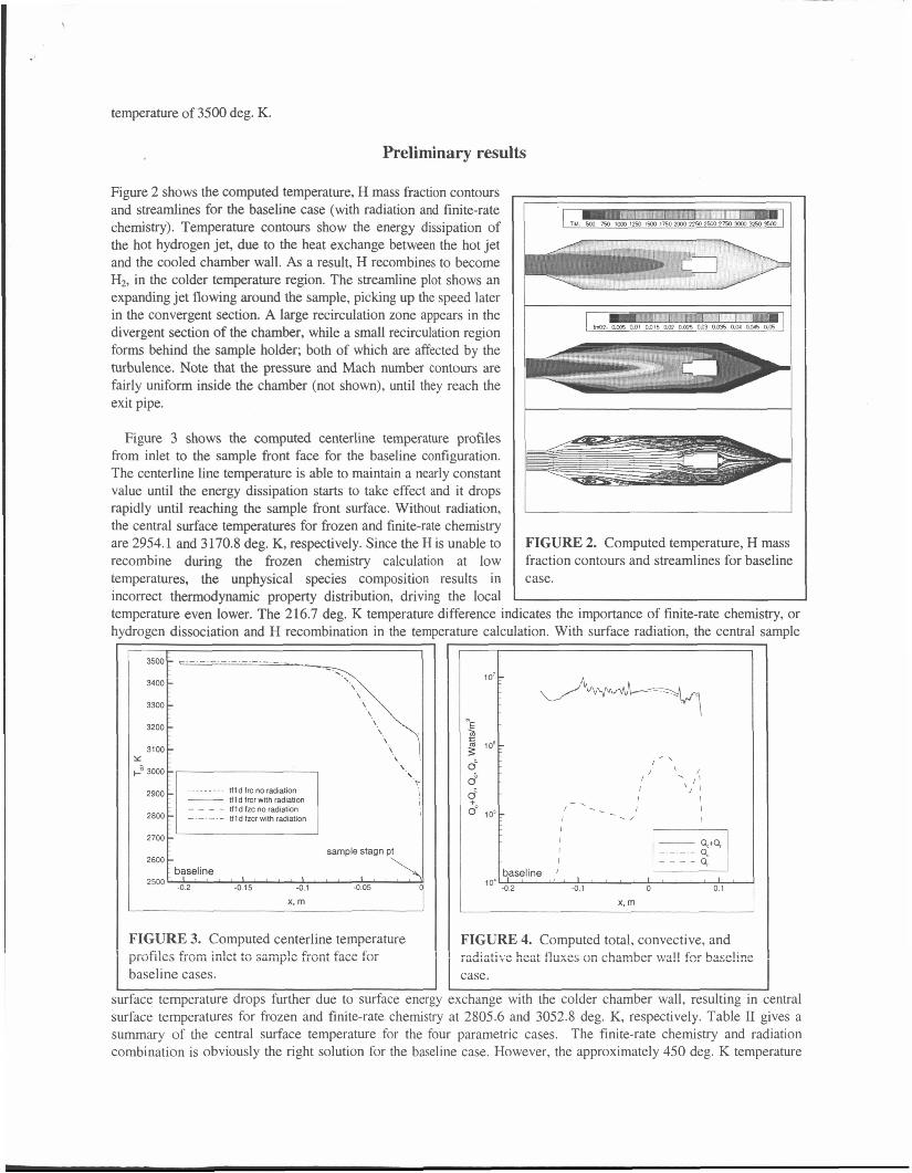
A funnel in front of the coupon was thought to improve on both aspects, because it concentrates the hot hydrogen flow while partially shielding the convective energy exchange between the hot jet and the cooled chamber. And it also serves as a partial radiation-shield with which some of the surface radiations are fended off.
Figure 5 shows the computed temperature, H concentration and streamlines for the funnel case. Again the higher concentration of H associates with higher temperatures. It can also be seen that the expansion of the hot hydrogen jet is suppressed and converged into a more energy concentrated jet. This can be seen from the slower decreasing slope of the central surface temperature profiles in Fig. 6, and the surface temperatures of 3172.0 deg. K (with radiation) and 3191.7 deg. K (without radiation). The surface temperature drop with and without radiation is now only 19.7 deg. K, indicating that the funnel indeed serves as a partial radiation shield.
I heat flux is above 5x10⁶ Wattdm', with a peak
FIGURE 5. Temperature, H mass fraction contours and streamlines for funnel case.
t
The funnel however, makes the flowfield not as uniform as that of the baseline case. When the higher energy,
c
t l lc lrc no radiation
2700 sample stagn pt
\ \ 2600
-0 15 -0.1 -0 05
x, m
'IGURE 6. Computed centerline temperature rofiles from inlet to sample front face for funnel ases.
lo5 t rIGURE 7. Computed total, convective, and radiative ieat fluxes on chamber wall for funnel case.

,
3300
3200
3100 Y
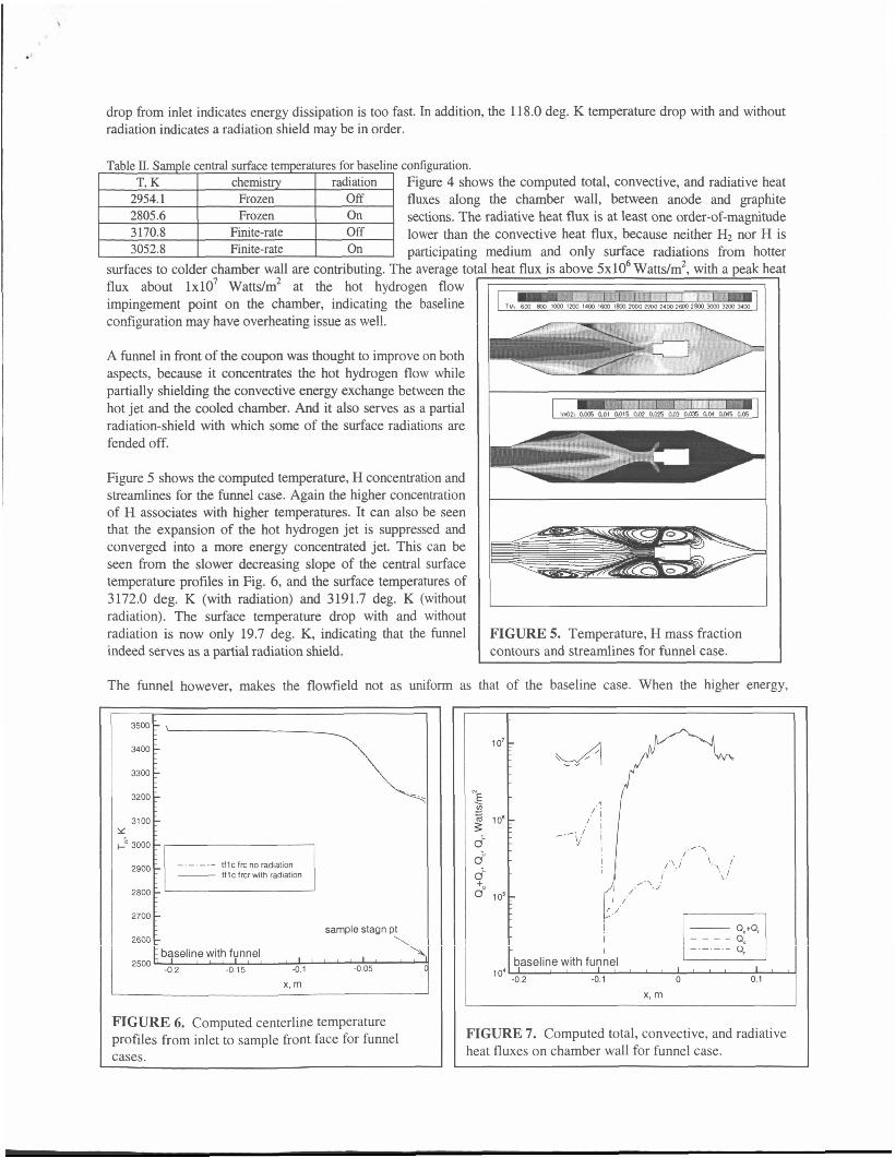
concentrated hot-hydrogen jet impinges on the sample, instead of flowing around it smoothly as in the baseline case, it forms a stronger jet impinging on the chamber wall, as indicated in the streamline plot in Fig. 5. That results in a peak total chamber wall heat flux of 1 . 5 4 ~ 1 0 ~ Watts/m2, exceeding the maximum heat flux desirable, as shown in Fig. 7.
L - - -
The final design (see Fig. 1) involves a Tungsten shield that almost completely shields the wall chamber from convective heating and it is supported by a 360 deg. Flange. The beginning of the shield is closed off at the intersection of the chamber and the anode section so that no hot flow can get in between the shield and chamber wall. In addition, this shield also serves as a radiation shield such that the central sample surface temperature should be at a maximum. Figure 8 shows the computed temperature, H concentration contours and streamlines for this design. It can be seen from the temperature contours that the flow is even more uniform - uniformly hot - than that of the baseline case. The H jet is now propagating the longest and wrapping around the coupon, indicating minimum energy dissipation for the hot jet. The H concentration between the chamber and the shield is lower because of lower local temperature due to convective heat transfer. The streamlines look very similar to those of the baseline case except the flow speed is a little faster due to smaller flowing area, resulting in a smaller recirculation bubble at the divergent section. All of these allow the central sample surface temperatures becoming very high among all three cases, i.e., at 3426.0 deg. K with radiation, and at 3440.7 deg. K without radiation. Figure 9 shows the slow dropping temperature profiles. The results of the central sample surface temperature for all three cases are summarized in Table III. Note the temperature difference with and without radiation is a lowest 14.7 deg. K for the
2800
2700
2600
I
- :
sample stagn pt - I baseline with shield config. 3
FIGURE 8. Computed temperature, H mass fraction contours and streamlines for baseline with shield configuration with radiation.
'IGURE 9 Computed centerline temperature profiles or shield configuration cases.
shield configuration, indicating that this shield is a very effec average total heat flux is now an acceptable 1 . 7 ~ 1 0 ~ Wattdn
I I(
FIGURE 10. Computed total, convective, and radiative heat fluxes on chamber wall for shield configuration. ,re radiation shield. In the mean time, Figure 10 shows the- ~
There is a peak total heat flux of 5 . 6 5 ~ 1 0 ~ Wattdm2 right

behind the close-off shield that is probably caused by the pre-determined 2600 deg. K for the chamber-facing shield surface. Since the close-off part of the shield is connected to the cold chamber wall at 400 deg. K, it is believed that the shield surface temperature at the close-off should be lower due to conduction, resulting in lower local gas temperature. Therefore that peak heat flux should be much lower if a conjugate heat transfer calculation was conducted. Furthermore, there is a second peak near the end of the shield at 3 . 4 6 ~ 1 0 ~ Watts/m2 which is again lower than the threshold, where a small recirculation bubble is formed at the mouth of the opening. In summary, the shield configuration is the best design among the 3 configurations and it was selected for the test fixture.
baseline I 3170.8 I 3052.8 funnel 3191.7 3172.0
Table 111. Sample central surface temperature for reacting flow cases. Case I No radiation, K I Radiation, K I A, K
118.0 19.7
I shield 3440.7 3426.0 14.7
BENCHMARK ANALYSIS
This computation is in progress. Laser diagnostics will be conducted to measure the central sample surface temperature and a centerline flow temperature at a short distance from the sample. These measured temperatures will be used to benchmark the computed temperatures. Conjugate heat transfer of the sample will be added. It is expected that this final analysis be done at the manuscript due date.
CONCLUSION
A computational methodology was developed to provide thermal-fluid environment in a nuclear thermal engine thrust chamber. It was developed in conjunction with a non-nuclear test effort entitled “Hot-Hydrogen Materials and Component Development.” Several design analyses were performed to determine the best design for the test fixture to ensure the integrity of the chamber and to minimize the energy dissipation of the hot-hydrogen jet. The shield configuration was selected over the baseline and funnel configurations. Code benchmark analyses are in progress to compare the predicted centerline flow temperature and the sample surface temperature with those of laser measurement.
NOMENCLATURE
CI, C2,Cj,Cp turbulence modeling constants, 1.15, 1.9,0.25, and 0.09. CP = heat capacity D = diffusivity H = total enthalpy I = radiative intensity K = thermal conductivity k = turbulent kinetic energy P = pressure Q = heat flux R = recovery factor r = location coordinate T = temperature ‘I“ = non-dimensional temperature t = time, s 4 4 = wall friction velocity X = Cartesian coordinates E e = energy dissipation contribution K = absorption coefficient P = viscosity
= mean velocities in three directions
= turbulent kinetic energy dissipation rate

Pr n P = density 0 = turbulence modeling constants t = shear stress D w
= turbulent eddy viscosity (=pC,k2k) = turbulent kinetic energy production
= direction vector. 0- denotes the leaving radiative intensity direction = chemical species production rate
Subscripts b = black body c = convective r = radiative t = turbulent flow
ACKNOWLEDGMENTS
This study was partially supported by a Nuclear Systems Office task entitled “Multiphysics Thrust Chamber Modeling” and by a MSFC Internal Research and Development focus area task entitled “Hot Hydrogen Materials and Component Development.”
RFERENCES
Koenig, D.R., “Experience Gained from the Space Nuclear Rocket Program (Rover)”, LA- 10062-H, Los Alamos National Laboratory, Los Alamos, New Mexico, May 1986. Wang, T.-S., “Multidimensional Unstructured-Grid Liquid Rocket Engine Nozzle Performance and Heat Transfer Analysis,” AIAA Paper 2004-4016, July 2004, to appear in Journal of Propulsion and Power. Chen, Y . -S. , and Kim, S . W., “Computation of Turbulent Flows Using an Extended k-E Turbulence Closure Model,” NASA CR-179204, Oct. 1987. Wang, T.-S., Chen, Y.-S., Liu, J., Myrabo, L.N., and Mead, F.B. Jr., “Advanced Performance Modeling of Experimental Laser Lightcraft,” Journal of Propulsion and Power, Vol. 18, No. 6, November-December, 2002, pp. 1129-1 138.