a new algorithm for instantaneous speed and position ... · a new algorithm for instantaneous speed...
TRANSCRIPT

TitleA new algorithm for instantaneous speed and positionestimation of surface-mounted permanent magnet synchronousmotors
Author(s) Yin, J; Lee, CK; Hui, RSY; Shrivastava, Y
Citation
The 5th Annual International Energy Conversion Congress andExhibition for the Asia/Pacific Region (ECCE Asia DownUnder2013), Melbourne, Australia, 3-6 June 2013. In IEEE ECCE AsiaDownunder (ECCE Asia) Proceedings, 2013, p. 518-524
Issued Date 2013
URL http://hdl.handle.net/10722/189864
Rights IEEE ECCE Asia Downunder (ECCE Asia) Proceedings.Copyright © IEEE.
A New Algorithm for Instantaneous Speed and Position Estimation of Surface-Mounted Permanent
Magnet Synchronous Motors
J. Yin, C.K. Lee and S.Y.R. Hui Department of Electrical & Electronic Engineering
The University of Hong Kong Hong Kong, China [email protected]
Abstract-This paper describes a patent-pending method that
can be used to estimate the speed and position of surface
mounted permanent magnet synchronous motors (SMPMSM) with
cylindrical rotor structure and sinusoidal back emf. The concept
involves the use of the power inverter's switching actions and
switching current to provide instantaneous real-time information
for extracting the speed information. The theory and algorithm are
included to explain the proposed concept, which has been verified
by simulations on a SMPMSM drive under the control of a
sensorless speed control scheme.
Keywords-permanent magnet synchronous motor (PMSM); speed estimation; position estimation; sensorless control.
I. INTRODUCTION
Reliability of mechanically-coupled speed sensors is an issue particularly in hostile working environment where wide temperature fluctuation, mechanical vibration and dust are factors affecting the lifetime of the speed sensors. Therefore sensorless control has been a hot research topic for over two decades. A variety of sensorless control techniques, primarily based on the d-q model, have been proposed [\-6]. Some methods involve the use of flux linkage estimation [1]. However, such kinds of methods have limitations at low or even zero speeds. For some other speed sensorless methods, the common way to overcome the zero-speed limitation is to energize the motor so as to kick start the speed before the speed sensorless method takes actions [2]. The d-q transformation model [ 3 - 6] tends to use the filtered or fundamental waveforms of the machine voltage and current for computation. Consequently, the switching ripples of the voltage and current waveforms and their associated real-time information are lost.
In this paper, a patent-pending instantaneous sampling method based on the power inverter switching actions and a trigonometry equality equation for estimating the speed and position of a surface-mounted permanent magnet synchronous motor (SMPMSM) with cylindrical rotor structure and sinusoidal back emf distribution is described [7]. The fundamental mathematical model is demonstrated at first. Then the proposed method to estimate the speed and position
978-1-4799-0482-2/13/$31.00 ©2013 IEEE 518
Y. Shravastava Department of Electrical & Information Engineering
The University of Sydney Australia
is elaborated with simulation verification and error analysis. Finally, a sensorless control scheme has been successfully implemented with the proposed method in the drive simulation study. The proposed algorithm for speed and position estimation performs well in the simulation study.
II. MATHEMATICAL MODEL
A Surface-Mounted Permanent Magnet Synchronous Motor (SMPMSM) has permanent magnets mounted on the surface of the rotor to provide the rotor magnetic field. With the assumption that the three-phase motor connected to the power inverter is symmetrical, the SMPMSM dynamic mathematical model in the a-b-c-axis stationary reference frame can be established. The equivalent circuit of the SMPMSM is shown in Fig. 1. The three-phase voltages of the SMPMSM can be described by the following equations:
dA va = rJa + __ a dt
. dAb Vb = r,ih +Tt dA
V =ri + __ c e sc dt
(1)
(2)
(3)
where Va, v" and Vc are the terminal phase voltages of the motor, rs is the resistance of the stator windings, ia, hand ic are the stator currents, d/dt is the differential operator, Aa, A" and Ac are the flux linkages of the three-phase windings. The flux linkages can be expressed as:
A-a =LSia+LMib+LMic+A-msin[8e (t)+80] (4)
A-b = Lsib + LM ic + LM ia + A-m sin [8e (t) + 80 -23TC] (5) 2TC Ac = L,\ic + LMia + LMih +Am sin[8eCt)+80 +3] (6)
where Ls is the self inductance of each phase of stator windings, and LM is the mutual inductance between different phases of stator windings. Note that the self and mutual

a
b c
Fig. 1. Three-phase SMPMSM equivalent circuit.
inductances are assumed to be independent of the rotor's angular position due to the cylindrical structural characteristic that a SMPMSM always has an uniform air gap, so they are constant parameters in (4)- (6). Am is the amplitude of the flux linkage established by the permanent magnets as viewed from the stator phase windings. 8eCt) is the electrical angular displacement of the rotor position related to time, and 80 is the initial electrical angle of the rotor position.
For star-connected stator windings, the relationship of currents obeys the following equation:
(7)
Therefore (4)- (6) can be rewritten in a decoupled form:
Aa = (LI -LM )ia + Am sin[8e (t) + 80]
Ab = (LI -LM )ib + Am sin[8e (t) + 80 -23n]
Ac = (L� -LM )ic + Am sin[8e (t) + 80 + 23n]
(8)
(9)
(10)
The corresponding decoupled equivalent circuit is shown in Fig. 2.
Substituting (8) - (10) into (I) - (3), the phase voltage equations can be re-written as:
. di P va = r,la +L d
; + 2 Am {Or cos[8e (t)+80] di P 2n
Vb = rJh + L_b +-Am{Or cos[8e (t)+80 --] . m 2 3 di. P 2n
Ve =rJe+L-' +-Am{Orcos[8e (t)+8o+-] m 2 3
(11)
(12 )
(l3)
where P is the number of poles, {Or = (2/ P) (d8e (t)/ dt) is the
mechanical angular speed of the rotor, and L = Ls -LM is an
inductive parameter integrating both self and mutual
519
a
b r,
c
Fig. 2. Decoupled three-phase SMPMSM equivalent circuit.
inductances. In the d-q reference frame model of SMPMSM,
L = Ld = Lq . Similarly the voltage equations can be expressed
in the trivial matrix form as:
dia dt cos [8e (t) + 80]
[:},,[tj+L dib P 2n + 2 Am {Or cos[8e (t)+80 --] dt 3
die 2n dt cos[8e (t) + 80 +3]
III. SPEED AND POSITION ESTIMATION
A. Estimation a/the Angular Speed a/the Rotor
Rearranging (11) - ( 1 3) ,
2 di I' {Oa = {Or cos[8e (t)+ 80] = -- (Va - rJa -L _a ) PAm . dt
(14)
(15)
{Ob = {Or cos[8e (t)+80 --] = -- (Vb -rJb -L_h ) (16) 2n 2 di 1* 3 PAm . dt 2n 2 . die I' {Oe = (Or cos[8. (t)+80 +-] =-- (Ve -rJ. -L- ) (17) c 3 P\" . , dt
where, di l*
is the instantaneous sampled value of the slope of dt the stator current. In general, a high sampling rate for the stator currents can be employed to derive the slopes of the currents. In a discretized form, the instantaneous slope of the stator current can be linearly approximated from the difference of the consecutive sampled values of the stator current over a small sampling time M (i.e. a high sampling frequency) as
iabe (n) - iabe (n -I)
At ( 18)

Note that (Oa, (Oh and (Oe are cosine functions that vary with time. The rotor speed information �. derived from the three equations in (15)-( 17) should be identical. The uniqueness of the proposed speed estimation method is to take advantage of the following trigonometric equality,
(19)
so that the instantaneous angular speed of the rotor can be expressed from (15) - (17) as:
(20)
Note that the direction of the rotor rotation can be determined from the rotor positions as will be explained later.
If the motor's parameters r" L, and Am can be regarded as constants, and the electrical variables Va, Vh, v'" and ia, ih, ie, are measurable instantaneously, (Oa, (Oh and (Oe can be calculated with the use of (15) -(17), and then the angular speed of the rotor can be determined with the use of (20).
1) Voltage terms In (15) - (17), the voltage terms Va, Vh, Ve are phase
voltages with respect to the neutral point of motor's stator windings. However in some cases, the neutral point of the stator windings may not be accessible externally. Consequently (15)-(17) cannot be used directly. Under such situation, it is necessary to transform the phase voltage variables into the terminal voltages such as the line-to-line voltages that can be measured directly.
Now define Vam Vbm and Vcn as the input three-phase voltages from a three-phase power source, such as from the three output terminals of a power inverter, relative to an arbitrary reference point n, and define Vn as the reference point's potential with respect to the neutral point of the motor's stator windings. Then, Va, Vh and Ve can be expressed as:
Va =Van+Vn Vb = Vbn +Vn Vc = Vcn +Vn
Since va +Vb +Vc = 0, Vn can be expressed as:
(21)
(22)
(23)
V = n V +v +v an bn en
(24) 3
So far, Va, Vh, v'" and (Om (Oh and (Oe can be determined with respect to phase voltages Vam Vbm and Vcm which are easily measured. It is convenient to select one of the three-phase terminals as the reference point, such as phase-a. In this case, n=a (and so van=O as they are the same point) and the voltage
520
of the reference point relative to the neutral point inside the motor is
Vba +vca V =v = n a 3
And the other two phase voltages can be obtained as
(25)
(26)
(27)
The three-phase voltage quantities Vm Vh, Ve can now be expressed in terms of two line-to-line voltage quantities as
[J 3 3
2 [::: ] 3 3 (28)
1 2 -- -
3 3
2) Current slope terms As far as the current slope (di / dt) terms are concerned,
there exist some non-differentiable points in the current waveforms during each switching cycle, as shown in Fig. 3 . If such a non-differentiable point occurs between two consecutive sampling instants, the current slope will be incorrectly calculated. This means the non-differentiable points would introduce serious errors to the estimation results. However, such non-differentiable points are caused by the switching actions of the power inverter, which alters the current slopes. Because the current control scheme and the switching actions are known, the errors by caused by the nondifferentiable points can be avoided.
It should be noted that more than one non-diffferentiable point between two consecutive sampling instants could exist if the switching frequency of the inverter is higher than the sampling frequency. Therefore, it is necessary to choose a current sampling rate much higher than the maximum inverter
11.5
;:s 11
. -
E � 1 05 B s; 1! 0- lD
9.5 07002
i(n-1 )
i(n-2)� �
�ondifferentiable Point .k-i(n)
Nondifferentiable Point
01003
.K'i(n+1)
I
07004 Time r (5)
Fig. 3. Nondiflerentiable points in the current curve.
o 7[

switching frequency.
There are two important points about the speed estimation method stated above:
• (15) - (17) are not independent of one another, and theoretically each one can be deduced out of the other two. Nevertheless, due to the linear approximation in (15) -(17), the measurement errors, the environmental noises, the fmite word length of the microprocessor, potential parameter drifting, and other unpredictable nonlinear factors of the practical system, the modeling equations are not perfectly balanced. To minimize such kinds of possible errors, it is desirable to use all of the three equations for practical implementations.
• (20) provides the absolute value of the instantaneous angular speed of the rotor. The direction of the rotation can be determined from the angular position of the rotor.
B. Estimation o{the Angular Position o/the Rotor
The rotor's angular position estimation method is based on the assumption that the rotor's position cannot vary considerably due to the mechanical inertia of the rotor. If the sampling frequency is high enough compared with the rotor's rotating speed, the variation of the rotor's position over two consecutive sampling instants is limited within a small range.
The sequences of Wm Wh, and We can be used to determine the rotor's angular position. Fig. 4 shows the typical variations of Wm Wh, and We sequences when the motor is running in the positive direction. The waveforms are divided into six segments within one period. Firstly by comparing values of Wa, Wb, and We> the segment of the rotor angle can be located. Next the inverse trigonometric function can be applied to find the exact value of the rotor's angular position as shown in TABLE I. In practical implementation, the near-linear portions of the sinusoidal waveform should be used to make sure that the estimation results are more robust and less sensitive to measurement errors. Based on the same approach, Fig. 5 and TABLE II provide the similar information for the opposite direction of rotation.
If the rotating direction is not given, for the first sampling instant we can get two possible position estimation values simultaneously, 8e+(n-l) from TABLE I and 8e_(n-l) from TABLE II. With respect to the next measuring instant, a new pair of 8ein) and 8e_(n) can be obtained. By comparing 8e+ and 8e- with their respective position values in the previous sampling instant, the angular displacements are obtained, i.e.
A8e+ (n) = 8e+ (n) -8e+ (n-1)
A8e_ (n) = 8e_ (n) -8e_ (n-1) (29)
(30)
If the rotating direction is positive, A8e+(n) > 0 and A8e_ (n) > 0, otherwise Me+(n) < 0 and A8e _ (n) < O. So the electrical position 8eCn-l) for the last instant, which is equal to either 8e+(n-l) or 8e_(n-l), is determined, and so is the direction of rotation.
521
Poslhve Rotahan
1 1 1 1 1 1 1 1 1 · · · 1· · 1 / . .,..- . t- . ....., . 1 1 1
� I 1 1 / " I · I Y " iii 1 " 1 1 / g" 1 1
w I 1 8
" 1 I 1 1 (
8:'- I 1 I
I I ·
8" I
"- 1 / 1 / "
�+ /
1 1
60
1 1 1
" 1 \1
.1
1\ I I \ 1 \ I 1 \ 1 1 1 I
. . .I. 1 1 1
300
I I I I I I 1 I I I
\1 · :1\
. I I "-I I I I
360
"
--00 ,
I /
420 481 Electrical Angular PosItion e, (degree)
FigA. Relationship between OJa, Olh, OJ, sequences and the rotor's electrical
angular position in positive rotating case.
TABLE I. ELECTRICAL ANGULAR POSITION 8e+ WHEN Wr > 0 .
Wa, Wh, We Sequence
wa > Wb :::: we
Wh :::: Wa > We
Wh > We :::: Wa
We :::: Wb > Wa
We > Wa :::: Wb
Wa :::: We > Wh
8e+ Range
0::::8 <� e 3
11: 211: -<8 <-3 - e 3
211: -::::8 <11: 3 e
411: 11:::::8 <-e 3
411: < 8 < 511: 3 - e 3
511: -::::8 <211: 3 e
8e+ Value
211: I wh --cos- (-) 3 IWrl
COS-' (I::
I)
411: -I We --cos (-) 3 IWrl
211: W -+cOS-I (_b ) 3 IWr I
211: -cos-l( Wa ) IWrl
411: 1 We -+cos- (-) 3 IWr I
By comparing Fig. 4 and Fig. 5, it can be seen that for the same sequences of Wm Wh, and We the positive version of position 8e+ and the negative version 8e- have an offset of 180°. So the estimation procedure can be further simplified. For every sampling instant, only 8e+ is calculated.
If A8e+(n) > 0,
8e(n-I)= 8ein-I), 8e(n) = 8e+(n),
Wren-I) > 0, wren) > 0; otherwise,
8e(n-I) = 8e_(n-I) = 8e+(n-I)± 180°,
8e(n) = 8e_(n) = 8e+(n)±180°,
wren -1) < 0, wr(n) < O.
Once the initial state of the motor has been determined, only the calculation of the position values in the positive sense

I --·i·� ...- "
� / I '" I v ( I " '" I " :if I
ifl I I 0" I I 0"' .1
0" I·· I I I I
60
Negative Rotabon
I I I I I I I I I I
" I I. I I \ I I I I \ I \1--.. " / I· I " / I " ./ ··r· I � . , I I I
120 180 240 300
. : . (j,)
' 0 . . . 1 ./ b
I I
. . I / _._ -
(j,) I
I
. I . C
{ . I
360 420 480 Electrical Angular Posibon e, (degree)
FigS Relationship between (!la, (!lb, (!le and the rotor's electrical angular
TABLE II. ELECTRICAL ANGULAR POSITION 8e_ WHEN Wr < 0 .
Ola, Olh, Ole Sequence
we � W" > Wa
We > Wa � Wh
Wa � We > Wb
Wa > Wb � We
Wh � Wa > We
W" > We � Wa
Se_ Range
0::::8 <� e 3 1t 21t -<8 <-3 - e 3 21t -::::8 <1t 3 e
41t 1t::::8 <-e 3 41t < 8 < 51t
3 - " 3 51t -::::8 <21t 3 e
Se_ Value
21t _I W" --cos (--) 3 IWr I
I ( Wa) cos --IWr I
41t -I We --cos (--) 3 IWr I 21t 1 Wb -+cos- (--) 3 IWr I
21t-cos-' (- Wa) IWr I
41t _I We -+cos (--) 3 IWr I is needed for the following instants, because the corresponding negative position values can be obtained automatically. Assume that the last instant's position is So, the two possible current positions are Se + and Se _ . Then calculate their displacements separately. The one closest to 1800 should be excluded, i.e.
the current position 8" = 8e+ , wr > 0 ;
otherwise, the current position 8" = 8e_ , wr < 0 .
An alternative way to find the current position of the rotor is to determine the integral of Olr with respect to the sampling time step. For every fixed time interval, the estimated position value is applied to avoid the accumulative error of the integral effect.
522
Resuming the aforementioned steps, one can estimate the electrical angular positions at subsequent measuring instants. The mechanical angular position of the rotor can be expressed as
(31)
The mechanical position estimated by this method is not absolute except for the case that the motor has only one pair of poles inside. In order to determine the initial position, several methods [8 - 11] that can kick start the motor can be considered when the proposed method is employed.
C. Simulation Verification
To verify the speed and posItIOn estimation method proposed, a SMPMSM is given with following parameters:
P=8 r,=0.55 n L=12.5 mH Am=0.175 Wb
The algorithm is first tested with a standard inverter-fed, close-loop control motor drive scheme based on a position sensor (which provides both position and speed information) in the simulation study. This is to check the accuracy of the estimated speed and position before we use these- estimated values for the close-loop control in a speed/position sensorless manner. The motor is started from standstill to 600 r/min and then the speed is reduced to zero speed under the condition of a constant load torque of 4 Nm. The power inverter switching actions, the terminal voltages and the line currents of the three phases are instantaneously monitored for applying the proposed method. Fig. 6 describes the Ola, Olh, Ole sequences. Fig. 7 and Fig. 8 show the estimated speed and position results (by the proposed method) and their simulated counterparts. The absolute errors for speed and position estimation are displayed together.
It is observed that even for the near-zero speed range the algorithm can still give reasonably accurate speed and position estimation. The error does not depend on the speed range. The estimation results are calculated directly from the equations and principles proposed above and no filter is used. For the
800 ,----,--------,-------,---,--------,------,------,-----===�
600
� 400 :s
8"'
8; -400
-600
-800 '-----_--'----_---'---_-----'-__ L-_--'---_---'--_-----' __ -'-----_---' o 01 02 03 04 05 06 07 08 09
Time (s)
Fig. 6. O)a, OJ" OJ, sequences.

Tlme (5)
Fig. 7. Motor speed and absolute error.
2000r--�-�-�--r--�-�-�--r---,
1500
� '-..' 1000
§ � � 500
� �
0 05r--�-�-�--r--�-�-�--r---,
� -0.1
� ::s -015
is J3 -0.2
-03
-O ,350�-c'---�---c'��L--�-�
OL
6---c'
0 7��
OL8
---c'O
9
Time (s)
Fig. 8. Rotor position and absolute error.
implementation of sensorless control scheme, a low-pass filter can be added to the feedback loop to improve the performance.
523
IV. SENSORLESS CONTROL IMPLEMENTATION
To implement the sensorless control scheme with use of the speed and position estimation method proposed, the typical field-oriented control is utilized [12 -15]. Instead of using a position or speed sensor, a speed/position estimator (Fig. 9) is used to provide the estimated motor speed dynamically to the speed controller to generate electromagnetic torque reference. The position estimator generates the real-time position information of the rotor for the current controller to do the Park transformation and then produce switching signals. In the control block of Fig. 9, no speed/position sensor is needed. Only the terminal voltages and currents are instantaneously sampled. The sampling frequency is 100 kHz and the maximum switching frequency of the hysteresis currentcontrol power inverter is about 5 kHz.
Satlmllion
Fig. 9. Block diagram of tbe control scheme.
OOO'---�--�---'----'r=====c=====� - - -Reference speed
600
400
'2 200
� 0
b.r -200
-400
·600
-8000O---=-'cc-----='c05�-----cO-'c75�--"-----c-,25'=---�, 5
Time (s)
Time (s)
Fig. 10. Motor speed and absolute error.
30,------.------,------,,------,------,------,
Time (5)
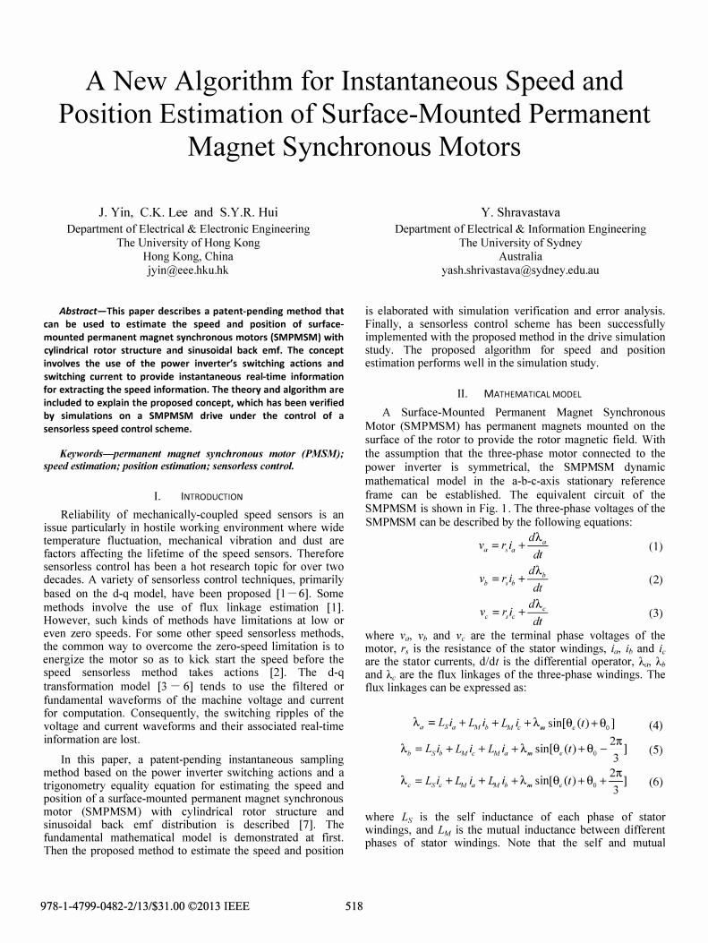
Fig. 11. Electromagnetic torque.
The parameter of the motor are selected to be the same as those in section III. The motor is started from standstill to 600 rev/min in one direction. At the time instant OAs, the motor speed is reduced to -600 rev/min in the opposite direction. At 1.1 s it starts braking and finally returns to zero speed again. Initially a constant load torque of 4 Nm is applied. At the time instant O.Ss the load torque is changed to - 8 Nm. To simplify the simulation, the initial position of the rotor is given. The speed response of the motor is described in Fig. 10 along with the error compared with the speed command. It can be seen that the proposed speed and position algorithm can achieve good performance for sensorless speed control. The electromagnetic torque is also plotted in Fig. 11.
V. CONCLUSION
In this paper, a patent-pending speed and posItIOn estimation method for SMPMSM is proposed. The mathematical deductions and principles are elaborated. Simulation results are included to confirm this concept. Further work is needed to evaluate the effects of the non-linear motor parameters on the accuracy of this method. This method is mainly based on power inverter's switching actions and switching currents. In principle, it can be applied to zero speed. Its performance does not depend on the speed range. However, this method is only valid for SMPMSM and does not apply to interior permanent magnet synchronous motors.
524
References [1] M. F. Rahman, L. Zhong, M. E. Haque, and M. A. Ragman, "A direct
torque controlled interior permanent -magnet synchronous motor drive without a speed sensor," IEEE Transactions on Industry Energy Conversion, vol. 18, no. 1, pp. 17-22, Mar., 2003.J.
[2] 1. H. Jang, S. K. Sui, 1. I. Ha, K, Ide, and M. Sawamura, "Sensorless drive of surface-mounted pennanent-magnet motor by high-frequency signal injection based on magnetic saliency," IEEE Transactions on Industry Applications, vol. 39, no. 4, pp. 1031-1039, Jul.lAug., 2003.
[3] S. Bolognani, M. Zigliotto, and M. Zordan, "Extended-range PMSM sensorless speed drive based on stochastic filtering," IEEE Transactions on Power Electronics, vol. 16, no. 1, pp. 110-117, Jan. 2001.
[4] J. L. Shi, T. H. Liu, and Y. C. Chang, "Adaptive controller design for a sensorless IPMSM drive system with a maximum torque control," lEE Proceedings on Electric Power Applications, vol. 153, no. 6, pp. 823-833, Nov. 2006.
[5] J. L. Shi, T. H. Liu, and Y. C. Chang, "Position control of an interior permanent-magnetic synchronous motor without using a shaft position sensor," IEEE Transactions on Industrial Electronics, vol. 54, no. 4, pp. 1989-2000, Aug. 2007.
[6] D. Yousfi, A. Halefadl, and M. EI Kard, "Review and evaluation of some position and speed estimation methods for PMSM sensorless drives," in International Conference on Multimedia Computing and Systems, ICMCS '09, 2009, pp. 409-414.
[7] S. Y. R. Hui, "Apparatus and method for providing information relating to a motor," US patent application 12/501,645, Jul. 2009.
[8] P. B. Schmidt, M. L. Gasperi, G. Ray, and A. H. Wijenayake, "Initial rotor angle detection of nonsalient pole permanent magnet synchronous machine," in Conf. Rec. IEEE-lAS Annu. Meeting, New Orleans, LA, 1997, pp. 459-463.
[9] M. Tursini, R. Petrella, and F. Parasiliti, "Initial rotor position estimation method for PM motors," IEEE Transactions on Industry Applications, vol. 39, no. 6, pp. 1630-1640, Nov.lDec. 2003.
[10] J Persson, M. Markovic, and Y. Perriand, "A new standstill position detection technique nonsalient pennanent-magnet synchronous motors using the magnetic anisotropy method," IEEE Transactions on Magnetics, vol. 43, no. 2, pp. 554-560, Feb. 2007.
[11] S. Y. Yun, H. J. Lee, I. G. Kim, and J. Lee, "Research on the starting methods for initial drYing PMSM," in 15th International Conference on Electrical Machines and Systems, ICEMS '09, 2012, pp. 1-5.
[12] P. C. Krause, "Analysis of electric machinery," McGraw-Hili, 1986.
[13] P. Pillay, and R. Krishnan, "Modeling of pennanent magnet motor drives," IEEE Transactions on Industrial Electronics, vol. 35, no. 4, pp. 537-541, Nov. 1988.
[14] P. Pillay, and R. Krishnan, "Control characteristics and speed controller design for a high performance permanent magnet motor drive," IEEE Transactions on Power Electronics, vol. 5, no. 2, pp. 151-159, Apr. 1990.
[15] B. K. Bose, "Modern power electronics and ac drives," Prentice-Hall, N. J. , 2002.