a new era of mortgage lending - iowa finance authority
TRANSCRIPT
1
PRESTRESSED CONCRETE STRUCTURES
Amlan K. Sengupta, PhD PE
Department of Civil Engineering,
Indian Institute of Technology Madras
Module – 2: Losses in Prestress
Lecture – 10: Creep, Shrinkage and Relaxation Losses
Welcome back to Prestressed Concrete Structures. This is the third lecture in the module
on losses in prestress.
(Refer Slide Time: 01:16)
In this lecture, we shall study the long term losses of prestress due to creep of concrete,
shrinkage of concrete and relaxation of prestressed steel. We shall also learn how to
calculate the total time-dependent loss. First is the loss due to creep of concrete.

2
(Refer Slide Time: 01:44)
The creep of concrete is defined as the increase in deformation with time under constant
load. Due to the creep of concrete, the prestress in the tendon is reduced with time.
(Refer Slide Time: 02:02)
The details of creep of concrete were explained in the module on Introduction,
Prestressing Systems and Material Properties. Here, the information is summarised.

3
(Refer Slide Time: 02:14)
The variation of strain with time, under a constant axial compressive stress, is represented
in the above figure. Here, the time is plotted in the horizontal axis and the strain in the
vertical axis. When we apply the prestress, there is an immediate strain, and then there is
a gradual increase in the strain with time. If the initial stress is limited within a certain
fraction of the characteristic strength, then the increase in the strain due to creep stabilises
to a certain value. This final increase in the strain is termed as the ultimate creep strain
and denoted as εcr,ult.
4
(Refer Slide Time: 03:23)
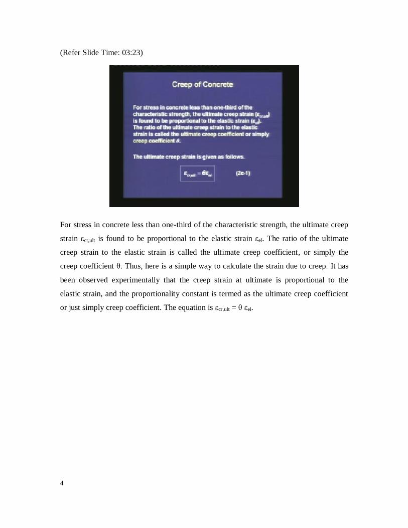
For stress in concrete less than one-third of the characteristic strength, the ultimate creep
strain εcr,ult is found to be proportional to the elastic strain εel. The ratio of the ultimate
creep strain to the elastic strain is called the ultimate creep coefficient, or simply the
creep coefficient θ. Thus, here is a simple way to calculate the strain due to creep. It has
been observed experimentally that the creep strain at ultimate is proportional to the
elastic strain, and the proportionality constant is termed as the ultimate creep coefficient
or just simply creep coefficient. The equation is εcr,ult = θ εel.

5
(Refer Slide Time: 04:27)
The creep strain depends on several factors. It increases with the following variables.
First, the cement content which influences the cement paste to the aggregate ratio. More
the cement paste we have, there is a higher chance of creep. Second is the water-to-
cement ratio. If water-to-cement ratio increases, then the strength of concrete decreases
and the creep goes up. Third is the air entrainment. If there are more air pockets within
the concrete, then creep increases. Fourth is the ambient temperature. If the temperature
is high, then it is observed that creep increases.

6
(Refer Slide Time: 05:21)
There are several factors for which the creep strain decreases. The first one is the age of
concrete at the time of loading. If we delay the loading of the concrete member, whether
it is the prestressing force or the service loads, it is found that the creep strain is reduced.
Second is the relative humidity. If the relative humidity goes up, the hydration gets better
and the creep strain reduces. The third is the volume-to-(surface area) ratio. If the
volume-to-(surface area) ratio increases, which means the exposed surface area
decreases, there is less loss of moisture, and it is found that the creep strain decreases.
The creep strain also depends on the type of aggregates. Usually, for synthetic aggregates
like pelletised fly ash, the creep strain can be higher.

7
(Refer Slide Time: 06:38)
The code IS: 1343 - 1980 gives some guidelines to estimate the ultimate creep strain in
Section 5.2.5. It is a simplified estimate, where only one factor has been considered. The
factor is the age of loading of the prestressed concrete structure. The creep coefficient θ is
provided for three values of the age of loading.
(Refer Slide Time: 07:04)
8
If the age of loading is 7 days, then the creep coefficient is 2.2, which means the ultimate
creep strain is more than twice the elastic strain. If we load it at 28 days, then the creep
strain is 1.6 times that of the elastic strain, and if we load the structure after 1 year then
the creep strain is slightly larger than the elastic strain. For all of the cases, the creep
strain is higher than the elastic strain.
(Refer Slide Time: 08:08)
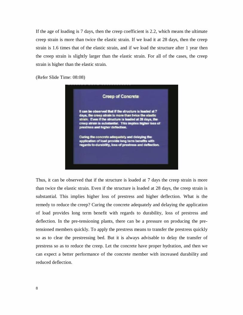
Thus, it can be observed that if the structure is loaded at 7 days the creep strain is more
than twice the elastic strain. Even if the structure is loaded at 28 days, the creep strain is
substantial. This implies higher loss of prestress and higher deflection. What is the
remedy to reduce the creep? Curing the concrete adequately and delaying the application
of load provides long term benefit with regards to durability, loss of prestress and
deflection. In the pre-tensioning plants, there can be a pressure on producing the pre-
tensioned members quickly. To apply the prestress means to transfer the prestress quickly
so as to clear the prestressing bed. But it is always advisable to delay the transfer of
prestress so as to reduce the creep. Let the concrete have proper hydration, and then we
can expect a better performance of the concrete member with increased durability and
reduced deflection.

9
(Refer Slide Time: 09:37)
The method that is given in the code to estimate creep is simple. In special situations,
detailed calculation may be necessary to monitor the creep strain with time. Specialised
literature or international codes can provide guidelines for such calculations.
(Refer Slide Time: 09:57)
Once we know the creep strain, the loss in the prestress due to creep is given as Δfp is
equal to the modulus of the prestressing steel times the ultimate creep strain. Here, we are

10
assuming a strain compatibility of the concrete and the prestressing steel. The amount of
strain the concrete undergoes, the same amount of strain the prestressing steel is also
undergoing. Hence, the drop in the prestress is equal to the modulus of the prestressing
steel times the strain which we are calculating for the ultimate creep.
(Refer Slide Time: 10:47)
When we are calculating the loss in prestress, the following considerations are applicable.
First, the creep is due to the sustained loads only. The sustained loads are the permanent
loads. Temporary loads are not considered in the calculation of creep. Usually, the dead
load which includes the self-weight, is a permanent load. A fraction of the live load may
be permanent, like the furniture and the book shelves in a library are considered to be a
sustained load. But in some situation, the full live load may be considered to be
temporary, like in a bridge structure. Hence, appropriate judgment has to be made to
consider whether the live load is sustained or what fraction of the live load is sustained,
and then calculate the creep based only on the sustained load. The temporary load need
not be considered to calculate the creep.
The second consideration is since the prestress vary along the length of the member, an
average value of the prestress can be considered. For a post-tensioned member with a
curved profile of the tendon, the prestress can vary along the length because there will be

11
a loss due to friction. But we can consider an average prestress to make the calculations
simpler. Since there is a variation of the stress in the concrete, we can consider an
average value for the calculation of the creep of the full member.
(Refer Slide Time: 13:05)
The third consideration is that the prestress change due to creep, and the creep is related
to the instantaneous prestress. We have to remember that the creep depends on the
prestressing force, because the creep strain is equal to a certain factor times the elastic
strain. The elastic strain depends on the prestressing force. Hence, creep depends on the
prestressing force. Also, with creep the prestressing force is reducing. Thus, we observe
that the creep and prestressing force are interrelated.
To consider this interaction, the calculation of creep can be iterated over small time steps.
We can do a refined calculation by breaking up the time span into several time steps, and
we can recalculate the creep strain and the prestressing force at the end of each time step.
That will be a better calculation of the creep, instead of just lump sum calculation based
on the prestress at transfer.
We are moving on to the second long term loss, which is due to the shrinkage of
concrete.

12
(Refer Slide Time: 14:40)
The shrinkage of concrete is defined as the contraction due to loss of moisture. Due to the
shrinkage of concrete, the prestress in the tendon gets reduced with time. The shrinkage
of concrete was explained in details in the Module “Introduction, Prestressing Systems
and Material Properties”.
(Refer Slide Time: 15:03)

13
Here, we shall just summarise shrinkage, and how to estimate the shrinkage strain. The
above sketch shows the variation of shrinkage strain with time. Here, t0 is the time at
commencement of drying and εsh is the ultimate shrinkage strain.
From this curve, what we observe is that till we cure there is no shrinkage. But once the
curing stops and the member is allowed to dry, there is a shrinkage and gradually, the
strain stabilises to a certain value which we are representing as εsh. It is termed as the
ultimate shrinkage strain.
(Refer Slide Time: 15:58)
Like creep, shrinkage also depends on several factors. The shrinkage strain increases with
the following variables.
First is the ambient temperature. If the temperature goes up, then the loss of moisture is
rapid and the shrinkage strain goes up. Second is the temperature gradient in the member.
If the temperature gradient is high, then we observe that the shrinkage will be also high.
Third is the water-to-cement ratio. If the water-to-cement ratio is higher, it is a low grade
of concrete; loss of moisture is high and hence, the shrinkage is also high. The last factor
is the cement content. Just like creep, if the cement paste to aggregate is high, then the
shrinkage strain goes up.

14
(Refer Slide Time: 17:01)
The shrinkage strain decreases with the following variables. First is the age of concrete at
commencement of drying. If we cure the concrete for a longer period, and then if we
apply the prestress or put it into service, then shrinkage is low. Second is the relative
humidity. If the relative humidity goes up then hydration is better, loss of moisture is less
and shrinkage will be also less. Third is the volume-to-(surface area) ratio. If the exposed
surface area decreases, then the volume-to-(surface area) ratio increases, the loss of
moisture is less and hence, the shrinkage is also less. The shrinkage also depends on the
type of aggregates used for making the concrete.
15
(Refer Slide Time: 18:00)
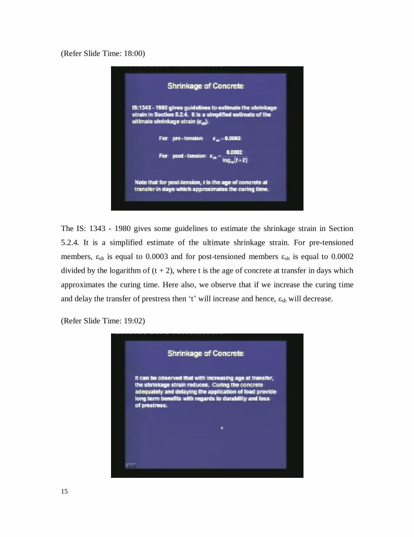
The IS: 1343 - 1980 gives some guidelines to estimate the shrinkage strain in Section
5.2.4. It is a simplified estimate of the ultimate shrinkage strain. For pre-tensioned
members, εsh is equal to 0.0003 and for post-tensioned members εsh is equal to 0.0002
divided by the logarithm of (t + 2), where t is the age of concrete at transfer in days which
approximates the curing time. Here also, we observe that if we increase the curing time
and delay the transfer of prestress then „t‟ will increase and hence, εsh will decrease.
(Refer Slide Time: 19:02)

16
Thus, with increasing age at transfer, the shrinkage strain reduces. Curing the concrete
adequately and delaying the application of load provide long term benefits with regards
to durability and loss of prestress. Just as we have seen for creep, similarly for shrinkage,
if the concrete member is properly cured and then if the prestress is transferred, then the
shrinkage strain will be less. The durability of the member will be better and the
deflection will get reduced.
(Refer Slide Time: 19:47)
In special situations, detailed calculations may be necessary to monitor shrinkage strain
with time. Specialised literature or international codes can provide guidelines for such
calculations. Shrinkage is a concern for liquid retaining structures. Restrained shrinkage
causes cracking, and the liquid can percolate out through those cracks. That will lead to a
problem of durability of the liquid retaining structure.

17
(Refer Slide Time: 20:25)
The loss in prestress (which is termed as Δfp) due to shrinkage is given as the modulus of
the prestressing steel times the shrinkage strain. Here also, we are assuming compatibility
between the strain in the concrete and the steel. If εsh is the strain in concrete due to
shrinkage, then the prestressing steel has a change in strain which is equal to εsh. The loss
in the prestress is equal to the change in the strain times the modulus.
The third type of long term loss is the relaxation of steel.
18
(Refer Slide Time: 21:20)
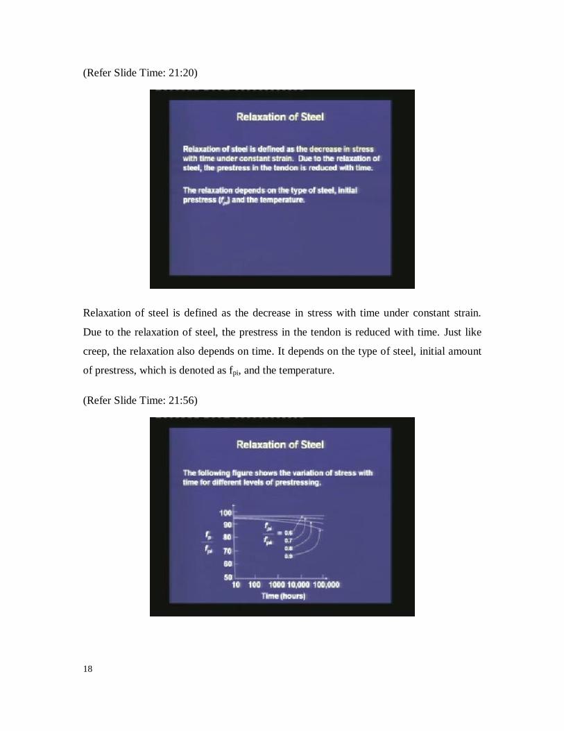
Relaxation of steel is defined as the decrease in stress with time under constant strain.
Due to the relaxation of steel, the prestress in the tendon is reduced with time. Just like
creep, the relaxation also depends on time. It depends on the type of steel, initial amount
of prestress, which is denoted as fpi, and the temperature.
(Refer Slide Time: 21:56)

19
This figure shows the variation of the stress with time for different levels of prestressing.
In the horizontal axis, we are plotting the time in a logarithmic scale. In the vertical axis,
we are plotting the instantaneous prestress normalised with the initial prestress. We
observe that if the initial prestress is about 60% of the characteristic strength, then the
change in the prestress is almost imperceptible. That means the relaxation loss is
insignificant. If the initial prestress is increased, say if it is 70% of the characteristic
strength, then we can notice a drop in the prestress. For 80% of the characteristic
strength, the drop is substantial. When we go for an initial prestress which is equal to
90% of the characteristic strength, the drop is extremely high, and that is not safe for the
structure.
(Refer Slide Time: 23:16)
Thus, it can be observed that there is a significant relaxation loss when the applied stress
is more than 70% of the characteristic tensile strength of the prestressing steel. Hence, the
code limits the maximum value of the prestress which is based on safety, and also from
the consideration of relaxation loss in the tendons. The calculation of the drop or loss in
prestress, was explained in the module of Introduction, Prestressing Systems and Material
Properties. In the absence of test data, the recommendations of IS: 1343 - 1980 can be
followed. The relaxation loss is given for 1000 hours and for a temperature of 27ºC.

20
(Refer Slide Time: 24:26)
If the initial prestress is 50% of the characteristic strength, then the relaxation loss is
negligible. It can be considered as zero. If the initial stress is 60% of the characteristic
strength, relaxation loss is 35 N/mm2. If the initial stress is 70% of the characteristic
strength, then the relaxation loss is 70 N/mm2. If the initial stress goes to the maximum
limit which is 80% of the characteristic strength, then the relaxation loss is 90 N/mm2.
We can see that this relaxation loss is a lump sum estimate, which is not depending on the
type of steel. If we need more detailed calculation of the relaxation loss based on the type
of steel, we can either get the information from the supplier of the steel or else we can do
some tests in the laboratory to find out the relaxation loss. We can also monitor the drop
in the prestress with time.

21
(Refer Slide Time: 25:00)
Let us understand the calculation of this long term loss by a simple example. A concrete
beam of dimension 100 mm 300 mm is post-tensioned with 5 wires of 7 mm diameter.
The average applied prestress after short-term losses is 70% of the characteristic strength,
which is equal to 1200 N/mm2. The age of loading is given as 28 days after the casting of
the concrete. Given that the modulus of the prestressing steel is equal to 200 103 MPa
and the modulus of concrete is equal to 35,000 MPa, find out the losses of prestress due
to creep, shrinkage and relaxation.
Note that, here we are not calculating the short term losses. We are just calculating the
long term losses. Before we start the calculations, we need to find out the geometric
properties. Here, the location of the CGS is given as 50 mm below the centroid of the
section; that means, the eccentricity of the CGS is 50 mm.

22
(Refer Slide Time: 27:12)
The area of concrete is 100 300 = 30,000 mm2. Next, we are calculating the moment of
inertia of the section, which is 100 3003 / 12 = 225 10
6 mm
4.
(Refer Slide Time: 27:41)
The total area of prestressing steel is equal to 5 times the area of each wire. The area of
each wire is given as /4 times the diameter square, and thus the total area of the
prestressing steel is 192.42 mm2. The prestressing force after the short term losses is

23
equal to the area of the prestressing steel times the prestress, which is equal to 192.4
1200 = 230.88 kN. This is the initial prestress after the short terms losses.
Now, we can calculate the drop in the prestress due to each of the long term loss, and
then try to find out an estimate of the total drop in the prestressing force.
(Refer Slide Time: 28:54)
We are calculating the modular ratio, which is the ratio of the moduli of the prestressing
steel and the concrete, and that is equal to 5.71. Next our objective is to find out the stress
in concrete at the level of CGS. Remember that when we are calculating the creep strain,
we first need to know the elastic strain, because we multiply the elastic strain by the
creep coefficient to get the ultimate creep strain. In order to get the elastic strain, we need
to know the stress in the concrete at the level of the CGS. The first term of the stress is
–P0/A, which represents a constant stress throughout the depth of the section. The second
term is P0e e divided by I. This term considers the eccentricity of the tendon „e‟. P0e is
the moment due to the eccentricity. Since, we are finding out the stress at the level of the
CGS, the distance from the centroid that we are interested in, is also equal to the
eccentricity e.
24
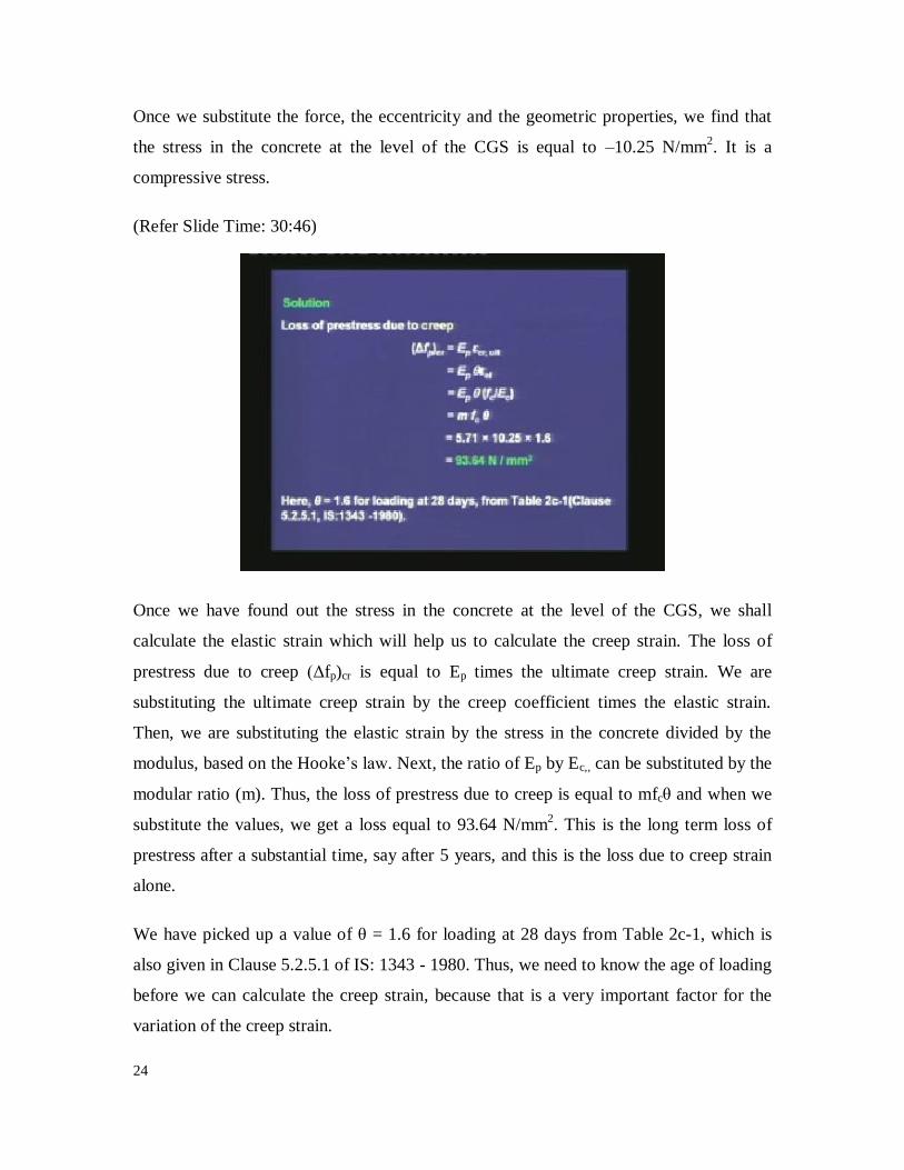
Once we substitute the force, the eccentricity and the geometric properties, we find that
the stress in the concrete at the level of the CGS is equal to ‒10.25 N/mm2. It is a
compressive stress.
(Refer Slide Time: 30:46)
Once we have found out the stress in the concrete at the level of the CGS, we shall
calculate the elastic strain which will help us to calculate the creep strain. The loss of
prestress due to creep (Δfp)cr is equal to Ep times the ultimate creep strain. We are
substituting the ultimate creep strain by the creep coefficient times the elastic strain.
Then, we are substituting the elastic strain by the stress in the concrete divided by the
modulus, based on the Hooke‟s law. Next, the ratio of Ep by Ec,, can be substituted by the
modular ratio (m). Thus, the loss of prestress due to creep is equal to mfcθ and when we
substitute the values, we get a loss equal to 93.64 N/mm2. This is the long term loss of
prestress after a substantial time, say after 5 years, and this is the loss due to creep strain
alone.
We have picked up a value of θ = 1.6 for loading at 28 days from Table 2c-1, which is
also given in Clause 5.2.5.1 of IS: 1343 - 1980. Thus, we need to know the age of loading
before we can calculate the creep strain, because that is a very important factor for the
variation of the creep strain.

25
(Refer Slide Time: 32:57)
Next, we are calculating the shrinkage strain from Clause 5.2.4.1 of the code IS: 1343 –
1980. Since it is a post-tensioned member, the shrinkage strain is given as 0.0002 divided
by the logarithm of (t+2), and in the problem t is 28 days. Once we substitute that, we are
able to find out the shrinkage strain in the member. This shrinkage strain is uniform
throughout the depth of the section. Hence, it is the same value at the level of the CGS.
The loss of prestress due to shrinkage (Δfp)sh is equal to the shrinkage strain times the
modulus of the prestressing steel and once we substitute the two values, we get a loss of
prestress equal to 27.08 N/mm2.

26
(Refer Slide Time: 34:07)
Third, we are calculating the loss of prestress due to relaxation. From Table 2c-2, which
is same as Table 4 of IS: 1343, we find that for an initial stress of 70% of the
characteristic strength, (Δfp)rl is equal to 70.0 N/mm2.
(Refer Slide Time: 34:33)
We have calculated the loss of the prestress for the creep, shrinkage and relaxation,
individually. Next, we are calculating the loss of the prestressing force. The loss of the

27
prestressing force is given as the drop in the prestress times the area of the prestressing
steel. The loss of prestressing force due to creep is equal to 93.64 192.42 = 18,018 N.
The loss of prestressing force due to shrinkage is equal to 27.08 192.42 = 5,211 N. The
loss of prestressing force due to relaxation is equal to 70 192.42 = 13,469 N. Thus, we
have calculated the loss of the prestressing force due to the creep, shrinkage and
relaxation, individually.
(Refer Slide Time: 35:59)
To find out the total long-term loss of the prestressing force, a simple way is to over-
estimate the total loss by neglecting the interaction of the losses and prestressing force.
We add the individual losses together to get the total long-term loss of 36,698 N. The
percentage loss of prestress is equal to this total drop divided by the applied prestress at
transfer times 100%, which comes around 16%.
Thus, we can observe that first when we apply the prestress, there is a short-term loss due
to the friction, anchorage slip and elastic shortening. We have seen that for a pre-
tensioned member, the loss due to elastic shortening can be substantial. For a post-
tensioned member, the friction and the anchorage slip can be substantial; especially, if the
member is long. Now, we can observe that the long term loss, which happens over a
period can also be substantial. For the above problem, we can see that the drop in

28
prestress is 16%. This was the reason, why prestressed concrete initially was not getting
the confidence of the designers. It was observed that the effective prestress was reducing
with time. In the earlier days, before the use of high strength steel, the effective prestress
almost became zero. To circumvent this problem, the solution was to use high strength
steel along with high strength concrete, for which even after the loss of the prestress with
time, there will be a residual prestress, which will be satisfactory for the service loads.
Now, we are calculating the total time dependent loss.
(Refer Slide Time: 38:27)
In the loss of prestress, the individual phenomena of creep and relaxation are dependent
on each other. The creep strain is dependent on the elastic strain, which is dependent on
the prestressing force. On the other hand, prestressing force reduces due to the creep
strain. Similarly, with relaxation, the prestressing force will drop that will affect the
creep. Hence, we observe that creep, shrinkage, relaxation and the prestressing force are
interrelated.
Earlier, we calculated each loss separately and added them up. This gives an over
estimate of the prestressing loss. The result may be adequate for simple construction. But,
when we are doing the calculations for more important structures, we have to refine our

29
calculations to include the interaction of the creep, shrinkage, relaxation on the
prestressing force.
(Refer Slide Time: 40:00)
To consider this inter-relationship of the cause and effect, the calculation can be done for
discrete time steps. We had seen before that the phenomena of creep, shrinkage,
relaxation are all dependent on time. The estimates that are given in the code IS: 1343 are
simple estimates, where the values are given only for the ultimate, and the time does not
appear as a function for any one of the losses. But if we want to do the calculations more
accurately, we have to use discrete time steps where we also need to have expressions of
creep, shrinkage and relaxation as functions of time. Such expressions are available in
specialised literature or the international codes, with which we can monitor each
individual loss with time. The results at the end of each time step are used for the next
time step. The basic idea is that we discretise the service life into several time steps, and
calculate the loss at the end of each time step by assuming that the prestressing force is
constant over the time step.
Once, we have computed the loss at the end of one time step, we re-calculate the
prestressing force. The new value of the prestressing force becomes effective for the next
time step. This means that, when we are doing the calculations for the next time step, we

30
use the revised value of the prestressing force. We calculate the losses at the end of the
second time step and from that, we again re-compute the prestressing force. The
calculation goes step by step, by which we are able to incorporate the inter-relationship
between the creep, shrinkage, relaxation and the drop in the prestressing force. This step-
by-step procedure was suggested by the Precast/Prestressed Concrete Institute committee
and it is called the General Method.
Precast/Prestressed Concrete Institute, in short PCI, is a professional organisation to
promote prestressed and precast concrete in the United States. The following method is
given in a paper written by a PCI committee. The title of the paper is “Recommendations
for Estimating Prestress Losses”. It was published in the PCI Journal, Vol. 20, No. 4, in
the months of July-August 1975, and the pages are from 43 to 75.
(Refer Slide Time: 43:36)
In the PCI step-by-step method, a minimum of four time steps are considered in the
service life of a prestressed member. As I said before, that in this procedure we are
discretising the service life of a structure into several time steps. This method suggests
that the minimum number of time steps that we need to consider is four. The
discretisation is a rational one based on the variations of the creep and shrinkage with

31
time. That is why in the initial period, the discretised steps are small, and then the steps
are larger, because the variations of creep and shrinkage get stabilised with time.
(Refer Slide Time: 44:34)
The time steps are as follows. The first time step starts with the anchorage of steel for a
pre-tensioned member. For a post-tensioned member, it starts with the end of curing. The
end of the first time step is the age of prestressing. For a pre-tensioned member once we
have anchored the steel, if we take substantial time to cast the concrete, cure the concrete,
cut the steel and transfer the prestress, by that time, there is some relaxation loss of the
steel because it has been holding against the end abutments. For a post-tensioned
member, once we have cured the concrete and applied the prestress after a certain time,
we will have some shrinkage strain before the prestressing, which is not considered as
part of the loss. But, if the prestressing is done right after the end of curing, then we do
not deduct any part of shrinkage from the calculation of long-term loss.
The second time step starts at the end of first step. It starts at the age of prestressing and
ends at 30 days after prestressing, or when subjected to superimposed load. In the first
month, the creep and shrinkage can be substantial. Hence, we are evaluating the losses
over the first 30 days, or if the time to impose the load is more than 30 days, then we may

32
consider the period from the age of prestressing to the time when the member is subjected
to the superimposed load.
The third time step starts from the end of the second time step, that means after 30 days
after prestressing to the first year of service. Thus, the third time step considers the loss of
prestress for the first service year. Because it has been found that creep and shrinkage can
be substantial in the first year of the service, we need to recompute the prestressing force
after the first year of service.
Finally, the fourth time step starts with the end of the third time step which is the first
year of service, and it ends with the end of service life which may be 50 years.
To summarise, creep, shrinkage and relaxation are related to the drop in the prestressing
force. If we calculate the losses individually and add them up, that is an over estimate of
the total prestressing loss. For important structures, we need to do a more precise
calculation, considering the interaction between the creep, shrinkage, relaxation and the
drop in the prestressing force. The method to do this is the step-by-step method which has
been proposed by the PCI committee.
In the step-by-step method, we discretise the service life of the prestressed member into a
minimum of four steps, and this division is based on the variation of the creep and
shrinkage. The first time step is crucial for a pre-tensioned member, wherein there can be
relaxation of the tendons till the prestressing is transferred to the concrete. The first time
step may not be crucial for a post-tensioned member, if the prestressing is right after the
end of curing. The second time step is from the age of prestressing to 30 days after
prestressing. Since, the creep and shrinkage are substantial in the first month, we
calculate the creep, shrinkage and relaxation losses, and recompute the prestressing force.
The third time step starts from the end of the first month and ends at the first year of the
service life. Here also we observe that in the first year of service life, the losses can be
substantial and hence, we need to recompute the prestressing force after the first year of
the service life. Finally, in the fourth time step, we are starting at the end of the first year
and doing the calculations of the total loss after a substantial period which is say, equal to
33
the end of the service life of the structure. This will give the final values of the creep,
shrinkage and the relaxation losses and the drop of the prestressing force.
(Refer Slide Time: 51:12)
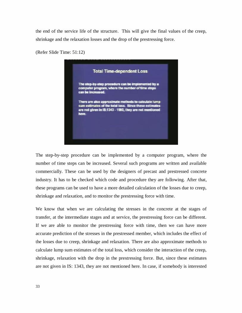
The step-by-step procedure can be implemented by a computer program, where the
number of time steps can be increased. Several such programs are written and available
commercially. These can be used by the designers of precast and prestressed concrete
industry. It has to be checked which code and procedure they are following. After that,
these programs can be used to have a more detailed calculation of the losses due to creep,
shrinkage and relaxation, and to monitor the prestressing force with time.
We know that when we are calculating the stresses in the concrete at the stages of
transfer, at the intermediate stages and at service, the prestressing force can be different.
If we are able to monitor the prestressing force with time, then we can have more
accurate prediction of the stresses in the prestressed member, which includes the effect of
the losses due to creep, shrinkage and relaxation. There are also approximate methods to
calculate lump sum estimates of the total loss, which consider the interaction of the creep,
shrinkage, relaxation with the drop in the prestressing force. But, since these estimates
are not given in IS: 1343, they are not mentioned here. In case, if somebody is interested

34
then the method recommended by the PCI committee or which are published in
recognised publications, can be used.
(Refer Slide Time: 53:15)
Today, we studied the loss of prestress due to the long term effects. First, we studied the
loss due to the creep of concrete. The creep is defined as the increase in strain in the
concrete under a constant stress. We have seen that, if the stress is limited within a certain
value of the characteristic strength, then the ultimate creep strain is proportional to the
elastic strain. The estimation of the ultimate creep strain is given by a simple expression,
where it is equal to a proportionality constant times the elastic strain.
The proportionality constant is called the creep coefficient. The creep depends on several
factors. It increases with a few variables and decreases with a few other variables. The
code IS: 1343 gives a simple procedure to estimate the ultimate creep strain. There the
coefficient is a function of only one variable which is the age at which the prestress is
transferred. We have observed that, if the age is large then the creep is reduced. Hence, if
we have to reduce the loss of prestress due to creep, then we should cure the concrete for
a longer period and delay the transfer of prestress. This will have long term benefits of
durability also. The loss of prestress is calculated from the creep strain by multiplying it
with the modulus of the prestressing steel. Here we assume strain compatibility between

35
the concrete at the level of the CGS with that of the steel, and once we know the drop in
the prestress, we can calculate the loss of the prestressing force by multiplying the drop in
the prestress with the area of the prestressing steel.
The second loss that we have studied was due to the shrinkage of concrete. The shrinkage
of concrete is the reduction of volume or the reduction of length with time, due to the loss
of moisture. Like creep, shrinkage also depends on several variables. It increases with
some of the variables and decreases with some other variables. The code IS: 1343 gives a
simple estimate of the shrinkage strain. For a pre-tensioned member it is higher, which is,
0.0003. For a post-tensioned member it is lower, but it depends on the age of concrete at
transfer. It has been assumed that, the age is the end of the curing period. Once we
estimate the shrinkage strain, we can find out the loss in the prestress by multiplying the
shrinkage strain with the modulus of the steel. The loss of the prestressing force is equal
to the loss of prestress times the area of the prestressing steel.
The third type of long term loss is due to the relaxation of steel, which is the drop in
stress at constant strain. The relaxation also depends on the type of steel, the amount of
initial prestress and the temperature. If the initial prestress is very high, if it is equal to
70% or more than the characteristic strength, then the relaxation losses can be substantial.
The code limits the initial prestress to about 80% of the characteristic strength for safety
reasons, as well as to limit the loss due to relaxation. The code gives us simple estimates
of the relaxation loss, which is a function of the initial prestressing force. The loss in the
prestressing force is equal to the drop in the prestress times the area of the steel.
We can have an estimate of the total long-term loss by adding up the individual losses.
But if we want to have a refined calculation, then we have to adopt a more accurate
procedure. We have learnt the step-by-step procedure suggested by the PCI, where the
time is discretised into small steps, and the prestressing force is updated after each step.
With this, we are ending the calculation of losses of prestress. In the next lecture we are
entering the third module, which is the analysis of prestressed concrete members.
Thank you.