a new fpga/dsp-based parallel architecture for real-time … · 2010-11-02 · a new fpga/dsp-based...
TRANSCRIPT

Real-Time Imaging 8, 345–356 (2002)doi:10.1006/rtim.2001.0273, available online at http://www.idealibrary.com on
A New FPGA/DSP-Based ParallelArchitecture for Real-Time ImageProcessing
In this article, we present a new reconfigurable parallel architecture oriented to video-ratecomputer vision applications. This architecture is structured with a two-dimensional (2D)array of FPGA/DSP-based reprogrammable processors Pij. These processors are inter-
connected by means of a systolic 2D array of FPGA-based video-addressing units which allowvideo-rate links between any two processors in the net to overcome the associated restrictions inclassic crossbar systems such as those which occur with butterfly connections. This architecturehas been designed to deal with parallel/pipeline procedures, performing operations which handlevarious simultaneous input images, and cover a wide range of real-time computer visionapplications from pre-processing operations to low-level interpretation. This proposed openarchitecture allows the host to deal with final high-level interpretation tasks. The exchange ofinformation between the linked processors Pij of the 2D net lies in the transfer of complete images,pixel by pixel, at video-rate. Therefore, any kind of processor satisfying such a requirement can beintegrated. Furthermore, the whole architecture has been designed host-independent.
# 2002 Published by Elsevier Science Ltd.
J. Batlle1, J. Martı1, P. Ridao1 and J. Amat2
1Computer Vision and Robotics Group,Institute of Informatics and Applications,
University of Girona, Av. Lluıs Santalo s/n,17071 – Girona, Catalonia, Spain
E-mail: {jbatlle,joanm,pere}@eia.udg.es2ESAII, Polytechnical University of Catalonia,
C/Pau Gargallo, 5-08028 Barcelona,Catalonia, Spain
E-mail:[email protected]
Introduction
Computer vision presents us with a widefield ofresearch incorporating a great amount of data and,consequently, requires a high level of processing
1077-2014/02/$35.00
capacity, mainly in parallel computing. Stated simply,computer vision can be separated into three mainlevels. The first one, the lower level, deals with pixel-operation functions such as differences between imagesand neighborhood filtering.
r 2002 Published by Elsevier Science Ltd.

Table 1. A parallel machine classification applied to computer vision systems, proposed by Sima et al. [1]
Parallelarchitectures
Data-parallelarchitectures
Vectorial
Associative and neuronal
SIMDs
Systolic
Function-parallelarchitectures
Pipeline processors
Instruction level VLIWs
(ILPs) Superscalar processors
Thread-levelMIMDs
Distributed memory MIMD(multicomputers)
Process-level Shared memory MIMD(multiprocessors)
346 J. BATLLE ETAL.
At the intermediate level, we kept in mind tasks suchas segmentation, motion estimation and feature extrac-tion or matching, all of which need pipelined processes.
At the upper level of computer vision we deal withinterpretation. This function usually requires ArtificialIntelligence tools as well as previous knowledge of theenvironment.
The challenge of pipelining these three levels in real-time can be undertaken using parallel architectures.
Table 1 shows a well-known classification presentedby Sima [1] in which the most representative groups offamilies are shown.
This table identifies some of the major families whichrepresent key junctures in the evolution of parallelismoriented to image processing. To date, these premisesare still quite valuable.
A great deal of work on parallelism has been carriedout over the past decade. However, most approaches,even the most recent ones, have been based on a handfulof historical architectures. In view of this, we shouldmention the systems based on a net of interconnectingmodules which process the whole image by localoperation on a pixeled neighborhood [2–6]. Thesearchitectures are generally based on geometric paralle-lism operating in a single instruction, multiple data(SIMD) mode. Moreover, pipelined systems and systolicnets of processors are based on multiple input processeswhose outputs constitute the inputs of the next opera-tion [7, 8], scanning the whole image and processing
it piece by piece. Thirdly, pyramidal systems computecomplex operations by using the divide and conquerparadigm [9, 10]. These architectures are frequently usedon multi-scalar or recursive operations such as imagegrabbing at different resolution levels. Furthermore,there are some architectures which are internallyorganized without taking into account the imagestructure or their operations [11–13]. Multiple instruc-tions, multiple data (MIMD) architectures, such asdigital signal processors (DSPs), permit the design ofseveral types of parallelism. Finally, hypercube proces-sors combine the advantages of pyramidal structuresand meshed nets [14,15].
Since architectures for real-time image processingneed to manage a large amount of data and work withinreal-time requirements, the use of parallelism is afundamental part of most of these systems. An interest-ing project considering specific architectures for paralle-lism was carried out by Raman and Clarkson [16]. Theirarticle describes a parallel architecture composed ofseveral specific, non-identical modules which can workconcurrently with only one shared memory.
Another interesting proposal was presented by Young[17], a DSPs-based structure which computes in parallelto solve tasks with a high computational cost, as in real-time image processing. He gives a few examples usingseveral DSPs from Texas Instruments, but mostspecifically the C40. Srinivasan and Govindaraj [18]have also used these devices (DSPs) in multi-processornetworks. To increase the process speed, they split theoriginal image into several independent blocks. Each
FPGA/DSP-BASEDPARALLEL ARCHITECTURE 347
block is then processed concurrently by the DSPs. Theyalso use Texas Instruments DSPs, in this case the C25.
Other projects, like Chen and Jen [19], show a specialprocessor for video signals. This processor is composedof several functional units which work in parallel.However, each unit in turn specializes in one kind ofcomputation (arithmetic unit, multiplicative unit, dis-crete cosine transform unit, and so forth). Anotherproject by Wu et al. [20], presents a co-processor built ofseveral basic modules interconnected by means of aprogrammable network.
The article by Turton et al. [21] is interesting sincethey attempt to apply genetic algorithms to computervision studies. To take advantage of this kind ofalgorithm they had to use parallelism and decided onparallel algorithms genetic (PAG), specifically the FineGrained version, which suggests that it is better to workwith a larger number of simple processors than withonly a few complex processors. Finally, the studies byBertozzi and Broggi [22] describe a stereo vision systemfor obstacle and lane detection. The kernel of thissystem is a parallel architecture called Paprica 3 which iscomposed of 256 processing elements (PEs) which workin an SIMD manner. We found that the GIOTTOsystem, an architecture proposed by Cucchiara [23] usedin robotics applications, was similar to the previouswork. This is also a parallel computer based on anSIMD reduced-size array processor with a novelorganization of the memory sub-system. Several of
Figure 1. The proposed architecture which constitutes a configu
these architectures are modular, which means that thesystem can be extended with more PEs or basic cells,depending on the application desired.
As far as our DSP/FPGA-based parallel architectureis concerned, this article is organized as follows. Firstly,in Section 3, the architecture and its performance arediscussed in general. Analog I/O video signal devices aswell as the systolic crossbar are briefly described inSection 4. Section 5 presents the architecture of theelemental processors and its hardware implementation.A brief overview concerning the control and synchro-nization of the whole architecture, as well as commu-nications with the host, is presented in Section 6.Finally, conclusions and further work are presented.
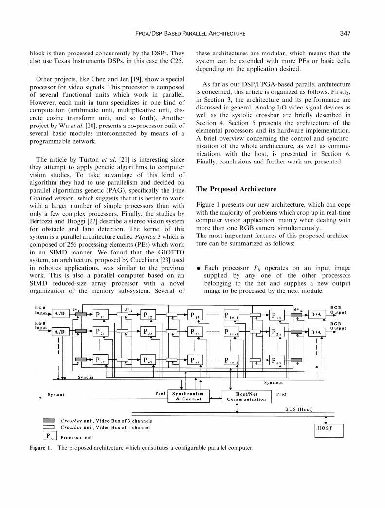
The Proposed Architecture
Figure 1 presents our new architecture, which can copewith the majority of problems which crop up in real-timecomputer vision application, mainly when dealing withmore than one RGB camera simultaneously.The most important features of this proposed architec-ture can be summarized as follows:
K Each processor Pij operates on an input imagesupplied by any one of the other processorsbelonging to the net and supplies a new outputimage to be processed by the next module.
rable parallel computer.

Figure 2. Systolic network of dv units which drives the video signal through the architecture.
Figure 3. A simplified architecture of the I/O buses for avideo-addressing cell [dvij].
348 J. BATLLE ETAL.
K The data BUS between processors have been designedfor byte-by-byte transmission, that is pixel by pixel.
K A set of digital video multiplexors (dvij) allowsparallel and pipeline connections betweenprocessors depending on the final application.
K Since only video-sync information and enable/disable control signals are considered, an FPGA-based processor (Pro1) controls the architecture.
K Processors are independent and perform differentimage-processing functions. Each processor controlsits own memory module. The same function can beparalleled as many times as needed.
K RGB images can be used as input/output.K All the processors can operate as a switch, allowingthe image to pass through without any inconvenience.In such cases, the video input is transferred straightaway to the output of the module.
We placed a processor (Pro1) in the overall control ofthe whole cell architecture, while another processor(Pro2) was in charge of communications with the host.Finally, a matrix of elemental processors [Pij] intercon-nected through a crossbar built with video-addressingprocessors called dvij to deal with the initial stages of thecomputing process was used. This crossbar constructionallows for all sorts of interaction among the basicprocessors [Pij] which can send or receive images pixelby pixel using a digital 8-bits BUS. Through Pro2, thisBUS is used to send information to the main host as well.
In the following, each module of the architecture will bedescribed in further detail, pointing out which kind ofdevices have been or will be used in future implementation.
Video Transmission
Analog input/output video signal
As mentioned before, multiple RGB input/outputsignals are possible when dealing with parallel
processing of various input images. As examples ofprobable applications requiring multiple parallel inputimages, we tested for three-dimensional (3D) imageprocessing, tracking, and object recognition.
In this architecture, every A/D module incorporates aPhilips TDA8709A converter and an LM1881 synchron-ism extractor. These synchronizational signals aresupplied to Pro1, the processor controlling the basicprocessors making up the net. The D/A conversion isperformed using TDA8702 devices.
The systolic crossbar
The video-addressing units [dvij] alone constitute a 2Dnet of FPGAs (see Figure 2) with the purpose of takingcare of video-transmission through the various basicprocessors [Pij] in the main architecture.
In such a net, we can differentiate between the input/output units addressing a 3� 8 video BUS from the restof the units addressing an 8-bit video BUS.
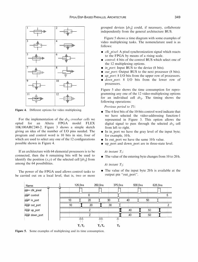
Figure 4. Different options for video multiplexing.
FPGA/DSP-BASEDPARALLEL ARCHITECTURE 349
For the implementation of the dvij crossbar cells weopted for an Altera FPGA model FLEX10K100ARC240-2. Figure 3 shows a simple sketchgiving an idea of the number of I/O pins needed. Theprogram and control word is 10 bits in size, four ofwhich are used to select any one of the 12 configurationspossible shown in Figure 4.
If an architecture with 64 elemental processors is to beconnected, then the 6 remaining bits will be used toidentify the position (x,y) of the selected cell [dvij] fromamong the 64 possibilities.
The power of the FPGA used allows control tasks tobe carried out on a local level, that is, two or more
Figure 5. Some examples of multiplexing and its time consump
grouped devices [dvij] could, if necessary, collaborateindependently from the general architecture BUS.
Figure 5 shows a time diagram with some examples ofvideo multiplexing tasks. The nomenclature used is asfollows:
K clk_pixel: A pixel synchronization signal which reactsto the FPGA by means of a rising scale.
K control: 4 bits of the control BUS which select one ofthe 12 multiplexing options.
K in_port: Input BUS to the device (8 bits).K out_port: Output BUS to the next processor (8 bits).K up_port: 8 I/O bits from the upper row of processors.K down_port: 8 I/O bits from the lower row ofprocessors.
Figure 5 also shows the time consumption for repro-gramming any one of the 12 video-multiplexing optionsfor an individual cell dvij. The timing shows thefollowing operations:
Previous period to T1:
K The 4 first bits of the 10-bits control word indicate thatwe have selected the video-addressing function-1represented in Figure 3. This option allows thedigital signal to pass through the selected dvij cellfrom left to right.
K In in_port we have the gray level of the input byte;for example, 10 h.
K In out_port we have the same 10 h value.K up_port and down_port are in three-state level.
At instant T1:
K The value of the entering byte changes from 10 to 20h.
At instant T2:
K The value of the input byte 20 h is available at theoutput pin ‘‘out_port’’.
tion.
350 J. BATLLE ETAL.
At instant T3:
K The value of the entering byte changes from 20 to30 h.
At instant T4:
K The value of the input byte 30 h is available at theoutput pin ‘‘out_port’’.
At instant T5:
K A change in the control signal produces the newfunction-6 configuration of the video-addressing cellto that represented in Figure 3.
The current prototype integrates the FPGA FLEX10-K250A.
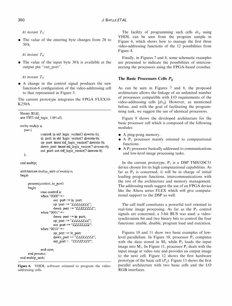
Figure 6. VHDL software oriented to program the video-addressing cells.
The facility of programming such cells dvij usingVHDL can be seen from the program sample inFigure 6, which shows how to manage the first threevideo-addressing functions of the 12 possibilities fromFigure 4.
Finally, in Figures 7 and 8, some schematic examplesare presented to indicate the possibilities of intercon-necting the processors using the FPGA-based crossbar.
The Basic Processors Cells Pij
As can be seen in Figures 7 and 8, the proposedarchitecture allows the linkage of an unlimited numberof processors compatible with I/O requirements of thevideo-addressing cells [dvij]. However, as mentionedbefore, and with the goal of facilitating the program-ming task, we suggest the use of identical processors.
Figure 9 shows the developed architecture for thebasic processor cell which is composed of the followingmodules:
K A ping-pong memory.K A P1 processor mainly oriented to computationalfunctions.
K A P2 processor basically addressed to communicationsand low-level image processing tasks.
In the current prototype, P1 is a DSP TMS320C51device chosen for its high computational capabilities. Asfar as P2 is concerned, it will be in charge of initialloading program functions, intercommunications withthe rest of the architecture and memory management.The addressing needs suggest the use of an FPGA devicelike the Altera series FLEX which will give computa-tional support to the DSP as well.
The cell itself constitutes a powerful tool oriented toreal-time image processing. As far as the P2 controlsignals are concerned, a 3-bit BUS was used: a video-synchronism bit and two binary bits to control the fourfunctions: enable, disable, program load and execution.
Figures 10 and 11 show two basic examples of low-level parallelism. In Figure 10, processor P1 computeswith the data stored in M2 while P2 loads the inputimage into M1. In Figure 11, processor P1 deals with theinput image at video rate and provides an output imageto the next cell. Figure 12 shows the first hardwareprototype of the basic cell (Pij). Figure 13 shows the firstparallel architecture with two basic cells and the I/ORGB interfaces.

Figure 7. Pipeline and parallel operations.
FPGA/DSP-BASEDPARALLEL ARCHITECTURE 351
To end this section, we would like to present anexample of how this basic cell (Pij) can be pro-grammed. The developed application consistsof loading a frame into the M1 memory andreading the previous frame from the M2 memory.Figure 14 shows a chart of the VHDL program.Figure 15 shows the code program. In summary, theDIV block is a simple frequency divider, while theRAMCTRL block is in charge or read/write memoryoperation.
Figure 8. Pipeline and parallel operations.
Control, Synchronization and Communication Tasks
Processor Prol – control and synchronization of the wholearchitecture
This processor is in charge of control and synchroniza-tional tasks. Its principal functions can be summarizedas follows:
K to supply external video-sync. signals for the videocameras,
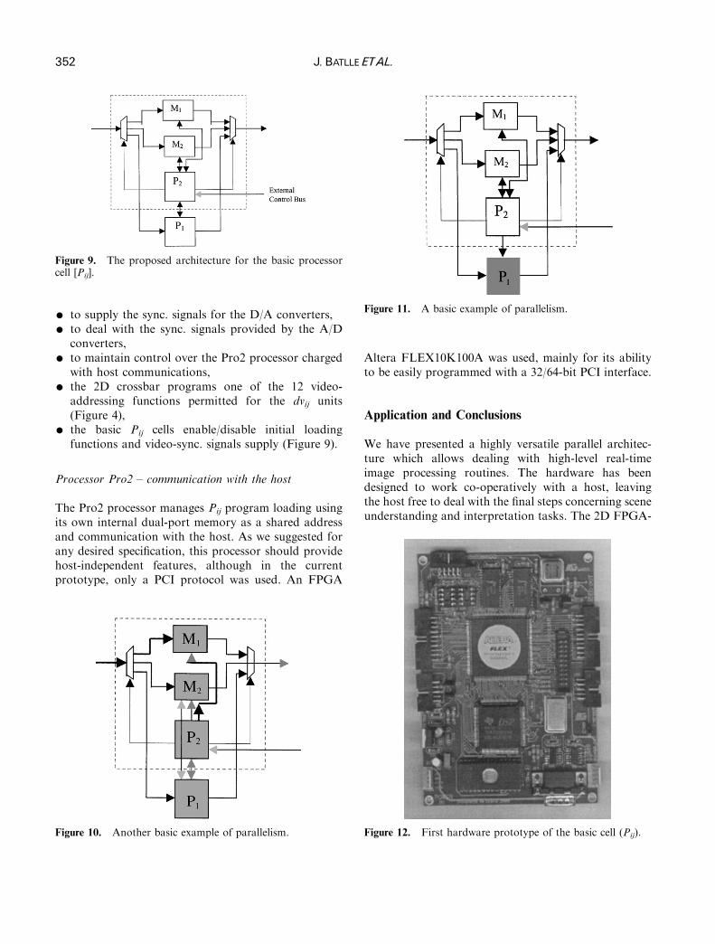
Figure 9. The proposed architecture for the basic processorcell [Pij].
Figure 11. A basic example of parallelism.
352 J. BATLLE ETAL.
K to supply the sync. signals for the D/A converters,K to deal with the sync. signals provided by the A/Dconverters,
K to maintain control over the Pro2 processor chargedwith host communications,
K the 2D crossbar programs one of the 12 video-addressing functions permitted for the dvij units(Figure 4),
K the basic Pij cells enable/disable initial loadingfunctions and video-sync. signals supply (Figure 9).
Processor Pro2 – communication with the host
The Pro2 processor manages Pij program loading usingits own internal dual-port memory as a shared addressand communication with the host. As we suggested forany desired specification, this processor should providehost-independent features, although in the currentprototype, only a PCI protocol was used. An FPGA
Figure 10. Another basic example of parallelism.
Altera FLEX10K100A was used, mainly for its abilityto be easily programmed with a 32/64-bit PCI interface.
Application and Conclusions
We have presented a highly versatile parallel architec-ture which allows dealing with high-level real-timeimage processing routines. The hardware has beendesigned to work co-operatively with a host, leavingthe host free to deal with the final steps concerning sceneunderstanding and interpretation tasks. The 2D FPGA-
Figure 12. First hardware prototype of the basic cell (Pij).
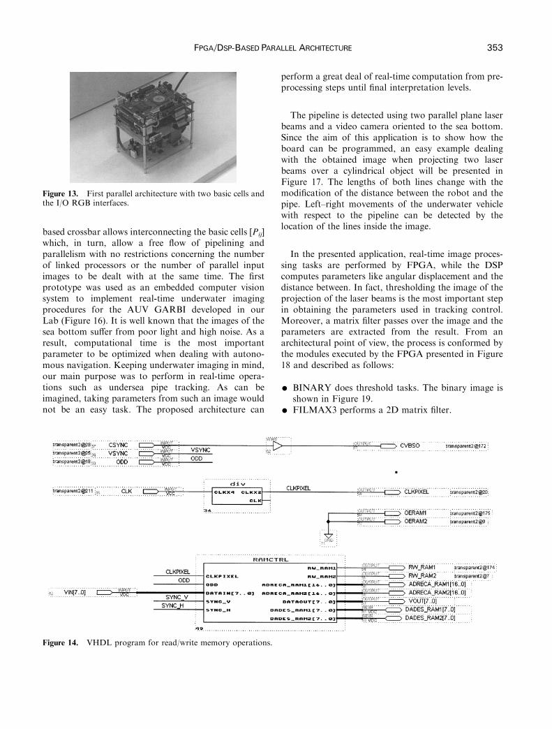
Figure 13. First parallel architecture with two basic cells andthe I/O RGB interfaces.
FPGA/DSP-BASEDPARALLEL ARCHITECTURE 353
based crossbar allows interconnecting the basic cells [Pij]which, in turn, allow a free flow of pipelining andparallelism with no restrictions concerning the numberof linked processors or the number of parallel inputimages to be dealt with at the same time. The firstprototype was used as an embedded computer visionsystem to implement real-time underwater imagingprocedures for the AUV GARBI developed in ourLab (Figure 16). It is well known that the images of thesea bottom suffer from poor light and high noise. As aresult, computational time is the most importantparameter to be optimized when dealing with autono-mous navigation. Keeping underwater imaging in mind,our main purpose was to perform in real-time opera-tions such as undersea pipe tracking. As can beimagined, taking parameters from such an image wouldnot be an easy task. The proposed architecture can
Figure 14. VHDL program for read/write memory operations.
perform a great deal of real-time computation from pre-processing steps until final interpretation levels.
The pipeline is detected using two parallel plane laserbeams and a video camera oriented to the sea bottom.Since the aim of this application is to show how theboard can be programmed, an easy example dealingwith the obtained image when projecting two laserbeams over a cylindrical object will be presented inFigure 17. The lengths of both lines change with themodification of the distance between the robot and thepipe. Left–right movements of the underwater vehiclewith respect to the pipeline can be detected by thelocation of the lines inside the image.
In the presented application, real-time image proces-sing tasks are performed by FPGA, while the DSPcomputes parameters like angular displacement and thedistance between. In fact, thresholding the image of theprojection of the laser beams is the most important stepin obtaining the parameters used in tracking control.Moreover, a matrix filter passes over the image and theparameters are extracted from the result. From anarchitectural point of view, the process is conformed bythe modules executed by the FPGA presented in Figure18 and described as follows:
K BINARY does threshold tasks. The binary image isshown in Figure 19.
K FILMAX3 performs a 2D matrix filter.

Figure 15. Code program for read/write memory operations.
Figure 16. The GARBI underwater robot.
Figure 17. Images taken by the camera from 2m.
354 J. BATLLE ETAL.
K CSERIE2 does the communication protocol RS232with the external devices, like PC.
K C_SERIE_N controls the input data flow from thePC, communication being done using the serial port.
K CONTROL_SERIE collects the signals to be sentthrough serial port and sends them to the previousblock.
K DSPCTRL does the communication function withthe DSP.
K GETOPTI is a buffer for initialization data. Theinformation taken from the image processing iscompared with the pre-set one.
K R_CONTROL2 processes the binary image. Itcomputes the distance between the lines appearingin the binary image, the position of the center of thefirst line and detects if one of the lines hasdisappeared from the image.
The system compares the information obtainedby processing the image with the pre-set values forthe optimum distance to be maintained between therobot and the pipeline. The DSP is used as acomplementary processor for computation ofthe displacement angle and the distance between Figure20 shows the implemented software in C-languagefor DSP.
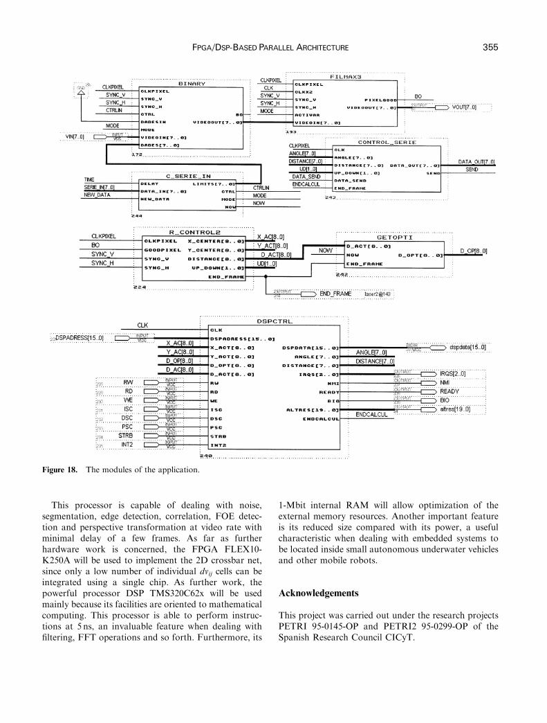
Figure 18. The modules of the application.
FPGA/DSP-BASEDPARALLEL ARCHITECTURE 355
This processor is capable of dealing with noise,segmentation, edge detection, correlation, FOE detec-tion and perspective transformation at video rate withminimal delay of a few frames. As far as furtherhardware work is concerned, the FPGA FLEX10-K250A will be used to implement the 2D crossbar net,since only a low number of individual dvij cells can beintegrated using a single chip. As further work, thepowerful processor DSP TMS320C62x will be usedmainly because its facilities are oriented to mathematicalcomputing. This processor is able to perform instruc-tions at 5 ns, an invaluable feature when dealing withfiltering, FFT operations and so forth. Furthermore, its
1-Mbit internal RAM will allow optimization of theexternal memory resources. Another important featureis its reduced size compared with its power, a usefulcharacteristic when dealing with embedded systems tobe located inside small autonomous underwater vehiclesand other mobile robots.
Acknowledgements
This project was carried out under the research projectsPETRI 95-0145-OP and PETRI2 95-0299-OP of theSpanish Research Council CICyT.
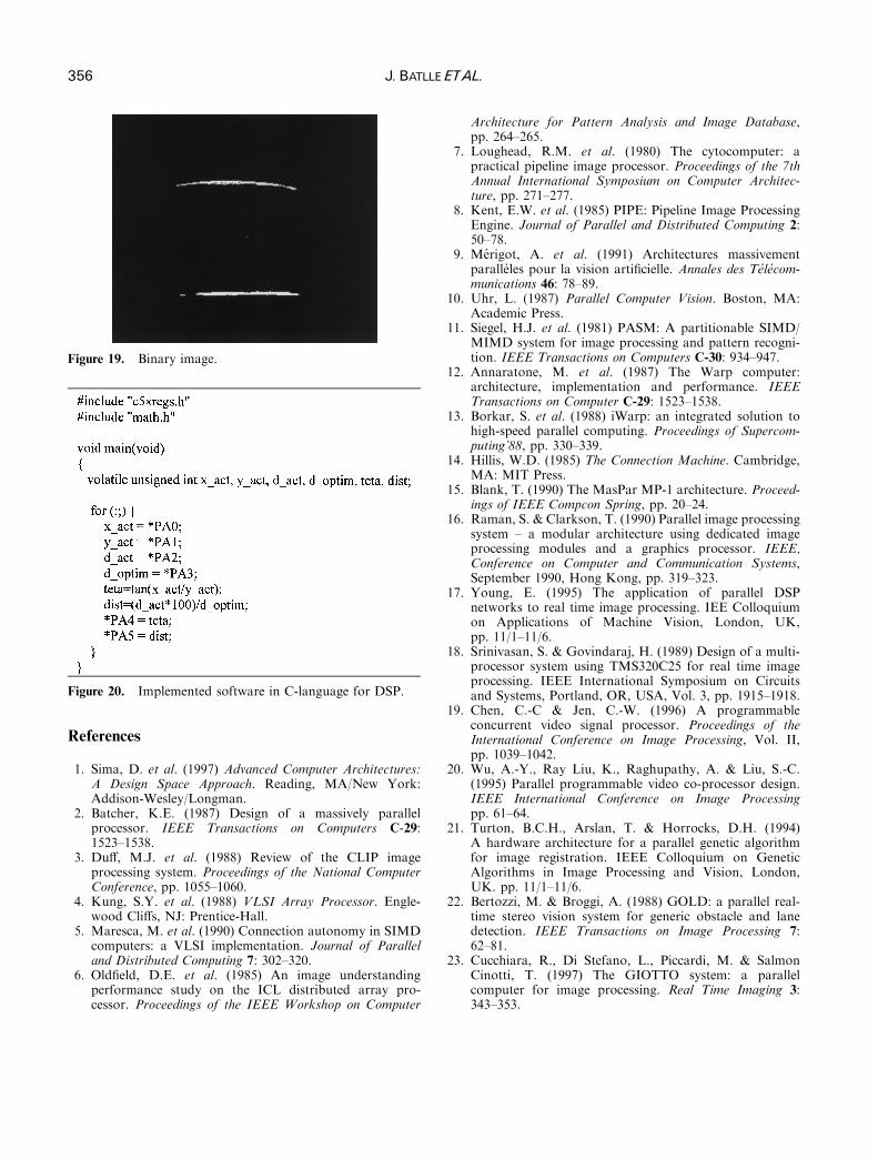
Figure 19. Binary image.
Figure 20. Implemented software in C-language for DSP.
356 J. BATLLE ETAL.
References
1. Sima, D. et al. (1997) Advanced Computer Architectures:A Design Space Approach. Reading, MA/New York:Addison-Wesley/Longman.
2. Batcher, K.E. (1987) Design of a massively parallelprocessor. IEEE Transactions on Computers C-29:1523–1538.
3. Duff, M.J. et al. (1988) Review of the CLIP imageprocessing system. Proceedings of the National ComputerConference, pp. 1055–1060.
4. Kung, S.Y. et al. (1988) VLSI Array Processor. Engle-wood Cliffs, NJ: Prentice-Hall.
5. Maresca, M. et al. (1990) Connection autonomy in SIMDcomputers: a VLSI implementation. Journal of Paralleland Distributed Computing 7: 302–320.
6. Oldfield, D.E. et al. (1985) An image understandingperformance study on the ICL distributed array pro-cessor. Proceedings of the IEEE Workshop on Computer
Architecture for Pattern Analysis and Image Database,pp. 264–265.
7. Loughead, R.M. et al. (1980) The cytocomputer: apractical pipeline image processor. Proceedings of the 7thAnnual International Symposium on Computer Architec-ture, pp. 271–277.
8. Kent, E.W. et al. (1985) PIPE: Pipeline Image ProcessingEngine. Journal of Parallel and Distributed Computing 2:50–78.
9. Merigot, A. et al. (1991) Architectures massivementparalleles pour la vision artificielle. Annales des Telecom-munications 46: 78–89.
10. Uhr, L. (1987) Parallel Computer Vision. Boston, MA:Academic Press.
11. Siegel, H.J. et al. (1981) PASM: A partitionable SIMD/MIMD system for image processing and pattern recogni-tion. IEEE Transactions on Computers C-30: 934–947.
12. Annaratone, M. et al. (1987) The Warp computer:architecture, implementation and performance. IEEETransactions on Computer C-29: 1523–1538.
13. Borkar, S. et al. (1988) iWarp: an integrated solution tohigh-speed parallel computing. Proceedings of Supercom-puting’88, pp. 330–339.
14. Hillis, W.D. (1985) The Connection Machine. Cambridge,MA: MIT Press.
15. Blank, T. (1990) The MasPar MP-1 architecture. Proceed-ings of IEEE Compcon Spring, pp. 20–24.
16. Raman, S. & Clarkson, T. (1990) Parallel image processingsystem – a modular architecture using dedicated imageprocessing modules and a graphics processor. IEEE,Conference on Computer and Communication Systems,September 1990, Hong Kong, pp. 319–323.
17. Young, E. (1995) The application of parallel DSPnetworks to real time image processing. IEE Colloquiumon Applications of Machine Vision, London, UK,pp. 11/1–11/6.
18. Srinivasan, S. & Govindaraj, H. (1989) Design of a multi-processor system using TMS320C25 for real time imageprocessing. IEEE International Symposium on Circuitsand Systems, Portland, OR, USA, Vol. 3, pp. 1915–1918.
19. Chen, C.-C & Jen, C.-W. (1996) A programmableconcurrent video signal processor. Proceedings of theInternational Conference on Image Processing, Vol. II,pp. 1039–1042.
20. Wu, A.-Y., Ray Liu, K., Raghupathy, A. & Liu, S.-C.(1995) Parallel programmable video co-processor design.IEEE International Conference on Image Processingpp. 61–64.
21. Turton, B.C.H., Arslan, T. & Horrocks, D.H. (1994)A hardware architecture for a parallel genetic algorithmfor image registration. IEEE Colloquium on GeneticAlgorithms in Image Processing and Vision, London,UK. pp. 11/1–11/6.
22. Bertozzi, M. & Broggi, A. (1988) GOLD: a parallel real-time stereo vision system for generic obstacle and lanedetection. IEEE Transactions on Image Processing 7:62–81.
23. Cucchiara, R., Di Stefano, L., Piccardi, M. & SalmonCinotti, T. (1997) The GIOTTO system: a parallelcomputer for image processing. Real Time Imaging 3:343–353.