a new framework for improving low quality fingerprint … a new framework for improving low quality...
TRANSCRIPT
1
A New Framework for improving low Quality Fingerprint Images
JitendraChoudhary Dr.Sanjeev Sharma Jitendra Singh Verma
SOIT RGPV Bhopal SOIT RGPV Bhopal SOIT RGPV Bhopal Email: [email protected] Email: [email protected] Email: [email protected]
Abstract Fingerprints are the oldest and most widely used
form of biometric identification. A fingerprint image
may not always be well defined due to elements of
noise that corrupts the clarity of the ridge structures
or basic information, which is required for
recognition. Noise may occur due to variations in
skin and impression condition. Thus, image
enhancement techniques are often used to reduce the
noise and enhance the structure of ridges and valleys
for minutiae detection. in this paper, we present a
fingerprint image enhancement method which can
adaptively improve the clarity of ridge and furrow
structures of input fingerprint image based on the
frequency and spatial domain filtering , local
orientation estimation , local frequency estimation
and morphological operation. There set of operation
applied on own database DB-Finger that Improve the
quality of fingerprint Image.
1. Introduction
Fingerprint identification is one of the most important
biometrics technologies which have received
increasingly more attention recently. Both the
academic and industry developed their own
algorithms and techniques for fingerprint recognition.
Fingerprints are used in many applications such as
forensics, access control etc. A fingerprint
identification system plays vital role in any
identification systems due to its uniqueness and
persistence. the fingerprint images are not always
provided with good quality due to skin conditions
(wet or dry, cuts, and bruises), sensor noise, incorrect
finger pressure, and worn-off ridges fingers (elderly
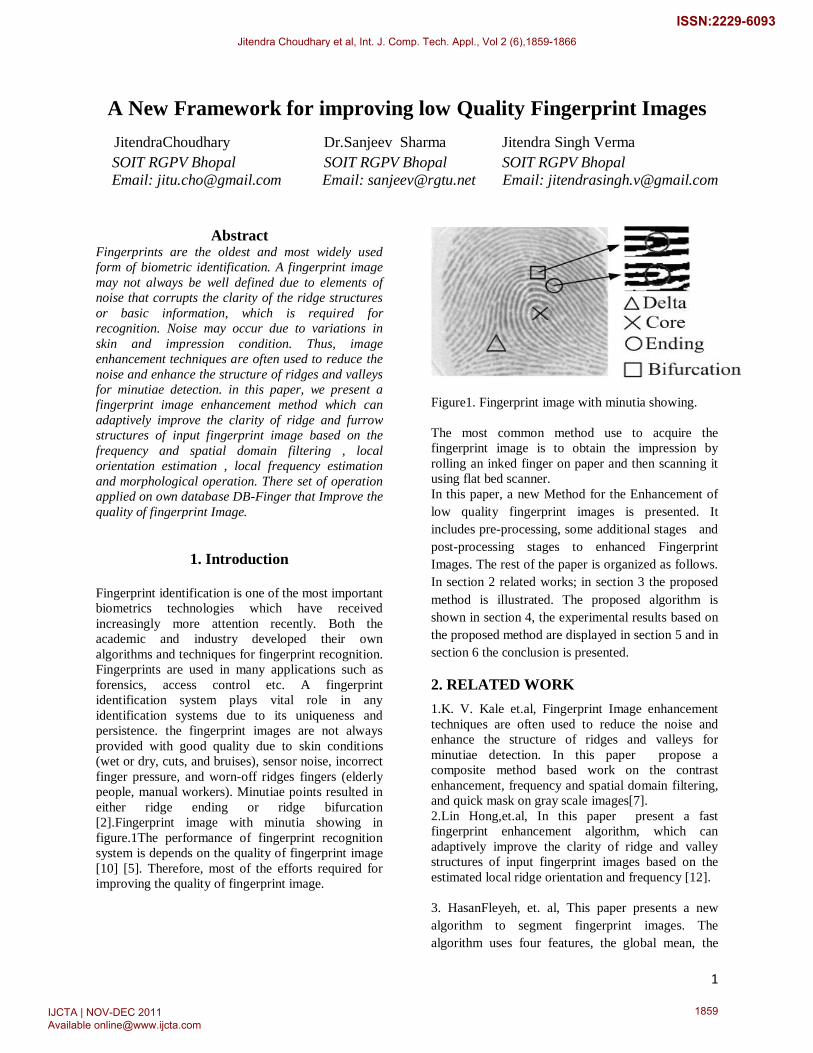
people, manual workers). Minutiae points resulted in
either ridge ending or ridge bifurcation
[2].Fingerprint image with minutia showing in
figure.1The performance of fingerprint recognition
system is depends on the quality of fingerprint image
[10] [5]. Therefore, most of the efforts required for
improving the quality of fingerprint image.
Figure1. Fingerprint image with minutia showing.
The most common method use to acquire the
fingerprint image is to obtain the impression by
rolling an inked finger on paper and then scanning it
using flat bed scanner.
In this paper, a new Method for the Enhancement of
low quality fingerprint images is presented. It
includes pre-processing, some additional stages and
post-processing stages to enhanced Fingerprint
Images. The rest of the paper is organized as follows.
In section 2 related works; in section 3 the proposed
method is illustrated. The proposed algorithm is
shown in section 4, the experimental results based on
the proposed method are displayed in section 5 and in
section 6 the conclusion is presented.
2. RELATED WORK
1.K. V. Kale et.al, Fingerprint Image enhancement
techniques are often used to reduce the noise and
enhance the structure of ridges and valleys for
minutiae detection. In this paper propose a
composite method based work on the contrast
enhancement, frequency and spatial domain filtering,
and quick mask on gray scale images[7].
2.Lin Hong,et.al, In this paper present a fast
fingerprint enhancement algorithm, which can
adaptively improve the clarity of ridge and valley
structures of input fingerprint images based on the
estimated local ridge orientation and frequency [12].
3. HasanFleyeh, et. al, This paper presents a new
algorithm to segment fingerprint images. The
algorithm uses four features, the global mean, the
Jitendra Choudhary et al, Int. J. Comp. Tech. Appl., Vol 2 (6),1859-1866
IJCTA | NOV-DEC 2011 Available [email protected]
1859
ISSN:2229-6093

2
local mean, variance and coherence of the image to
achieve the fingerprint segmentation. Based on these
features, a rule based system is built to segment the
image.
The proposed algorithm is implemented in three
stages; pre-processing, segmentation, and post
processing. Gaussian filter and histogram
equalization are applied in the pre-processing stage.
Segmentation is applied using the local features.
Finally, fill the gaps algorithm and a modified
version of Otsu thresholding are invoked in the post-
processing stage[1].
4. ShlomoGreenberg,et.al, In this work proposetwo
methods for fingerprint image enhancement. The first
one is carried out using local histogram equalization,
Wiener filtering, and image binarization. The second
method use a unique anisotropic filter for direct
grayscale enhancement. [8].
3. PROPOSED METHOD
Enhancement is a process for improving the
appearance or stability for particular image and its
applications. In fingerprint recognition system the
enhancement is an essential step for feature
extraction and matching. The overall performance of
the system is highly depends on quality of fingerprint
image i.e. good quality input image gives good
performance whereas poor quality image gives poor
performance. A fingerprint image enhancement
algorithm receives an input fingerprint image in pre-
processing stapes and applies a set of intermediate
steps on the input image, and the post-processing
steps, finally outputs the enhanced image. In order to
introduce our fingerprint image enhancement
algorithm, a list of notations and some basic
definitions are given below.
3.1 CONTRAST STRETCHING
The term spatial domain refers to the aggregate of
pixels used to compose the image. Spatial domain
methods are procedures that operate directly on the
pixels. Spatial domain process will be denoted by the
expression:
(1)
Where, f(x,y) is the input image, g is the
processed image and T is an operator on f defined
over some neighborhood of In addition T can
operate on a set of input images such as performing
the pixel by pixel some of k images for noise
reduction. T becomes a gray level operator also
called a gray level or mapping transformation
function [6] [5]. Through intensity mapping in our
experimental work we used the intensity stretching
technique using the gamma operator value 0.7.
3.2FREQUENCY AND SPATIAL FILTER
Frequency transformation discomposes an image
from its spatial-domain form of bright intensities into
a frequency domain form of frequency components
[9] as latent or fingerprint specialist are used to
dealing with a certain class of these images, we must
keep the subjective information brought by the
background. This background information is usually
removed by Appling Gaussian high-pass filter. The
foundation for linear filtering in both spatial and
frequency domain is the convolution theorem which
can be written as
(2)
and conversely,
(3)
Where, is the input image with filter
mask, F(u,v) is Fourier transform, and is
filter transfer function.In frequency domain filtering a
filter transform function modifies If high
frequency components of are attenuates and
low frequencies relatively unchanged then the
applied filter is lowpass filter.
High pass filter is defined as follows:
1-e-D(u,v)/2
(4)
Where, σ is the standard deviation, D(u,v) the
distance from point (u,v) to the center of the filter.
Fingerprint requires the enhancement of small areas
and details. A possible way of processing the image
is by considering not only the pixel itself, but also the
neighborhood of it at every location in the image [6] .
3.3 QUICK MASK EDGE DETECTOR
One of the principal approaches for edge detection is
based on the use of mask also called as filter, kernels,
templates, and windows. The quick mask is so named
because it can detect edges in all eight directions in
one convolution this as obvious speed advantages
when you want to detect all the edges [14].In the
experiment of this paper the quick mask of size 3-by-
3 is used to connect broken, cut and weak ridges of
all eight directions within only one convolution.
Jitendra Choudhary et al, Int. J. Comp. Tech. Appl., Vol 2 (6),1859-1866
IJCTA | NOV-DEC 2011 Available [email protected]
1860
ISSN:2229-6093
3
Following 3X3 matrix are used as a Quick Mask in
our method
-1 0 -1
0 4 0
-1 0 -1
3.4 AVERAGE FILTER
The Average (mean) filter smoothes image data, thus
eliminating noise. This filter performs spatial filtering
on each individual pixel in an image using the grey
level values in a square or rectangular window
surrounding each pixel. Here we use 5X5 average
filter
1/25 1/25 1/25 1/25 1/25
1/25 1/25 1/25 1/25 1/25
1/25 1/25 1/25 1/25 1/25
1/25 1/25 1/25 1/25 1/25
1/25 1/25 1/25 1/25 1/25
3.5NORMALIZATION
The next step in the fingerprint enhancement process
is image normalization [12]. Normalization is used to
standardize the intensity values in an image by
adjusting the range of grey-level values so that it lies
within a desired range of values. Let represent
the grey-level value at pixel (i; j), and N(i; j)
represent the normalized grey-level value at pixel
. The normalized image is defined as:
0+ 2
2
(5)
Where M and V are the estimated mean and variance
of I(i; j), respectively, and M0 and V0 are the desired
mean and variance values, respectively.
Normalization does not change the ridge structures in
a fingerprint; it is performed to standardize the
dynamic levels of variation in grey-level values,
which facilitates the processing of subsequent image
enhancement stages.
3.6ORIENTATION FIELD ESTIMATION
The orientation field of a fingerprint image represents
the directionality of ridges [5]. Fingerprint image
typically divided into number of non-overlapping
blocks and an orientation representative of the ridges
in the block is assigned to the block based on
grayscale gradients in the block. The orientation field
of block (i, j ) is given by
= -1Vy (I,j)
Vx (I,j) (6)
i+w/2 i+w/2
x = 2
x2
y
u=i-w/2 u= i-w/2 (7)
i+w/2 i+w/2
y = 2
x2
y
u=i-w/2 V=i-w/2 (8)
where w is the size of block . The orientation field of
a typical fingerprint image is shown in Fig.3.6 (The
orientation field is overlapped with the original
fingerprint image).
Fig .3.6 Oriented window and x-signature.
3.7 RIDGE FREQUENCY IMAGE
The gray levels along ridges and valleys can be
modeled as a sinusoidal-shaped wave along a
direction normal to the local ridge orientation (see
Fig.2.5). Therefore, local ridge frequency is another
intrinsic property of a fingerprint image. Let G be the
normalized image and 2 be the orientation image,
then the steps involved in local ridge frequency
estimation are as follows:
Jitendra Choudhary et al, Int. J. Comp. Tech. Appl., Vol 2 (6),1859-1866
IJCTA | NOV-DEC 2011 Available [email protected]
1861
ISSN:2229-6093
4
=
(9)
Therefore, the frequency of ridges and valleys can be
estimated from the x-signature. Let be the
average number of pixels between two consecutive
’
X
0
1 (11)
peaks in the x-signature, then the frequency,
is computed as: If no
consecutive peaks can be detected from the x-
signature, then the frequency is
l l
= ∑ ∑ l ’
u=- /2 v=- /2 (12)
Where is a two-dimensional low-pass filter with
unit integral and w l= 7 is the size of the filter.
3.8 REGION MASK
As mentioned early, a pixel (or a block) in an input
fingerprint image could be either in a recoverable
region or an unrecoverable region. Classification of
pixels into recoverable and unrecoverable categories
can be performed based on the assessment of the
shape of the wave formed by the local ridges and
valleys. In our algorithm, three features are used to
characterize the sinusoidal-shaped wave: amplitude
(α), frequency (β), and variance(γ).
be the x-signature of a block
centered at (i, j).
1 1
)2
i=1 i=1 (13)
3.9 GABOR FILTERING
Apply filters to enhance the ridge pattern; once the
ridge orientation and ridge frequency information has
been determined, these parameters are used to
construct the even-symmetric Gabor filter. A two
dimensional Gabor filter consists of a sinusoidal
plane wave of a particular orientation and frequency,
modulated by a Gaussian envelope [19]. Gabor filters
are employed because they have frequency-selective
and orientation-selective properties. The even-
symmetric Gabor filter is the real part of the Gabor
function, which is given by a cosine wave modulated
by a Gaussian .An even symmetric Gabor filter in the
spatial domain is defined as [16]:
1
=exp-
2
(14)
(15)
Where is the orientation of the Gabor filter, f is the
frequency of the cosine wave, and yare the
standard deviations of the Gaussian envelope along
the x and y axes, respectively, and and define
the x and y axes of the filter coordinate frame,
respectively.
3.10 BINARISATION
Most minutiae extraction algorithms operate on
binary images where there are only two levels of
interest: the black pixels that represent ridges, and the
white pixels that represent valleys. Binarisation is the
process that converts a grey level image into a binary
image. This improves the contrast between the ridges
and valleys in a fingerprint image, and consequently
facilitates the extraction of minutiae. One useful
property of the Gabor filter is that it has a DC
component of zero, which means the resulting
filtered image has a mean pixel value of zero.
Jitendra Choudhary et al, Int. J. Comp. Tech. Appl., Vol 2 (6),1859-1866
IJCTA | NOV-DEC 2011 Available [email protected]
1862
ISSN:2229-6093
5
3.11 THINNING
The final image enhancement step typically
performed prior to minutiae extraction is thinning.
Thinning is a morphological operation that
successively erodes away the foreground pixels until
they are one pixel wide. A standard thinning
algorithm [17] is employed, which performs the
thinning operation using two sub iterations.
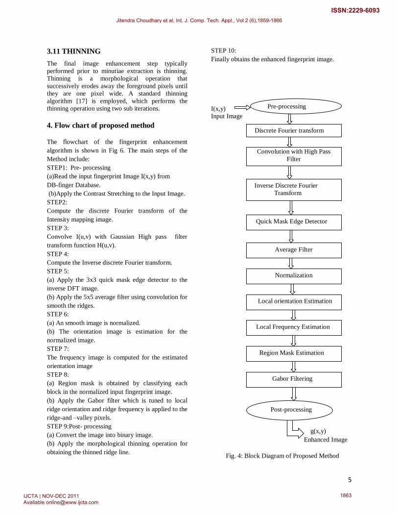
4. Flow chart of proposed method
The flowchart of the fingerprint enhancement
algorithm is shown in Fig 6. The main steps of the
Method include:
STEP1: Pre- processing
(a)Read the input fingerprint Image I(x,y) from
DB-finger Database.
(b)Apply the Contrast Stretching to the Input Image.
STEP2:
Compute the discrete Fourier transform of the
Intensity mapping image.
STEP 3:
Convolve I(u,v) with Gaussian High pass filter
transform function H(u,v).
STEP 4:
Compute the Inverse discrete Fourier transform.
STEP 5:
(a) Apply the 3x3 quick mask edge detector to the
inverse DFT image.
(b) Apply the 5x5 average filter using convolution for
smooth the ridges.
STEP 6:
(a) An smooth image is normalized.
(b) The orientation image is estimation for the
normalized image.
STEP 7:
The frequency image is computed for the estimated
orientation image
STEP 8:
(a) Region mask is obtained by classifying each
block in the normalized input fingerprint image.
(b) Apply the Gabor filter which is tuned to local
ridge orientation and ridge frequency is applied to the
ridge-and –valley pixels.
STEP 9:Post- processing
(a) Convert the image into binary image.
(b) Apply the morphological thinning operation for
obtaining the thinned ridge line.
STEP 10:
Finally obtains the enhanced fingerprint image.
I(x,y)
Input Image
g(x,y)
Enhanced Image
Fig. 4: Block Diagram of Proposed Method
Pre-processing
Discrete Fourier transform
Convolution with High Pass
Filter
Inverse Discrete Fourier
Transform
Quick Mask Edge Detector
Average Filter
Normalization
Local orientation Estimation
Local Frequency Estimation
Region Mask Estimation
Post-processing
Gabor Filtering
Jitendra Choudhary et al, Int. J. Comp. Tech. Appl., Vol 2 (6),1859-1866
IJCTA | NOV-DEC 2011 Available [email protected]
1863
ISSN:2229-6093
6
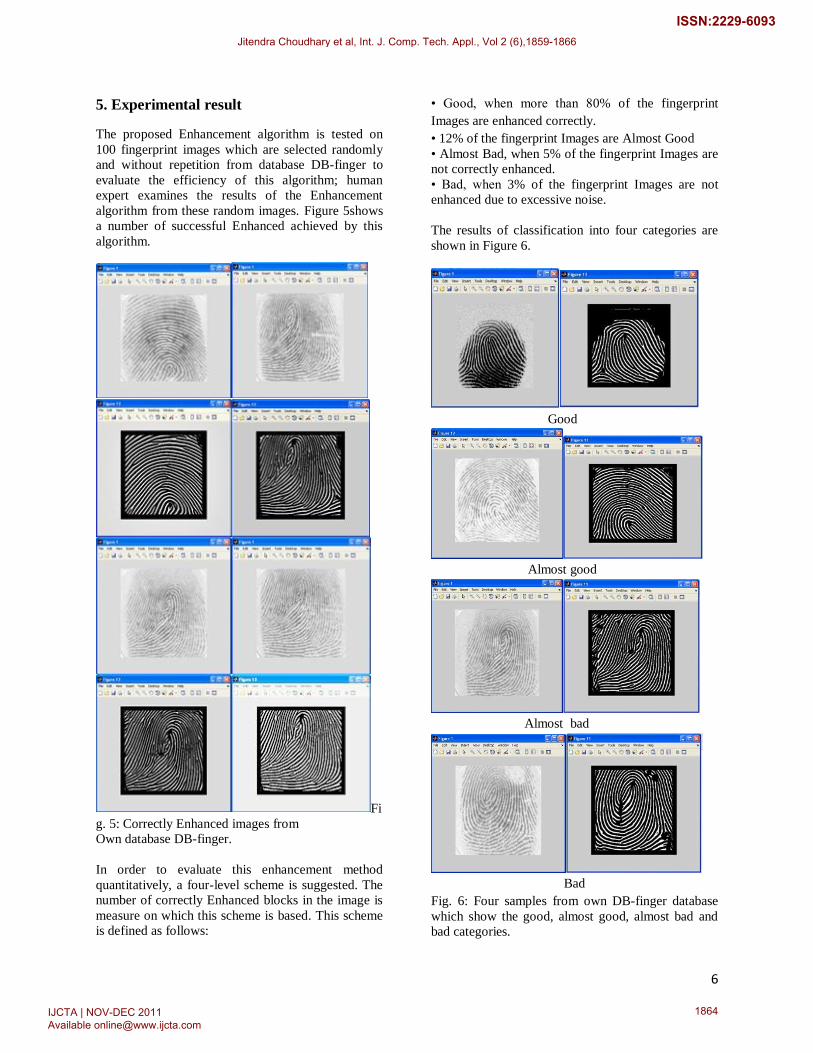
5. Experimental result
The proposed Enhancement algorithm is tested on
100 fingerprint images which are selected randomly
and without repetition from database DB-finger to
evaluate the efficiency of this algorithm; human
expert examines the results of the Enhancement
algorithm from these random images. Figure 5shows
a number of successful Enhanced achieved by this
algorithm.
Fi
g. 5: Correctly Enhanced images from
Own database DB-finger.
In order to evaluate this enhancement method
quantitatively, a four-level scheme is suggested. The
number of correctly Enhanced blocks in the image is
measure on which this scheme is based. This scheme
is defined as follows:
• Good, when more than 80% of the fingerprint
Images are enhanced correctly.
• 12% of the fingerprint Images are Almost Good
• Almost Bad, when 5% of the fingerprint Images are
not correctly enhanced.
• Bad, when 3% of the fingerprint Images are not
enhanced due to excessive noise.
The results of classification into four categories are
shown in Figure 6.
Good
Almost good
Almost bad
Bad
Fig. 6: Four samples from own DB-finger database
which show the good, almost good, almost bad and
bad categories.
Jitendra Choudhary et al, Int. J. Comp. Tech. Appl., Vol 2 (6),1859-1866
IJCTA | NOV-DEC 2011 Available [email protected]
1864
ISSN:2229-6093
7
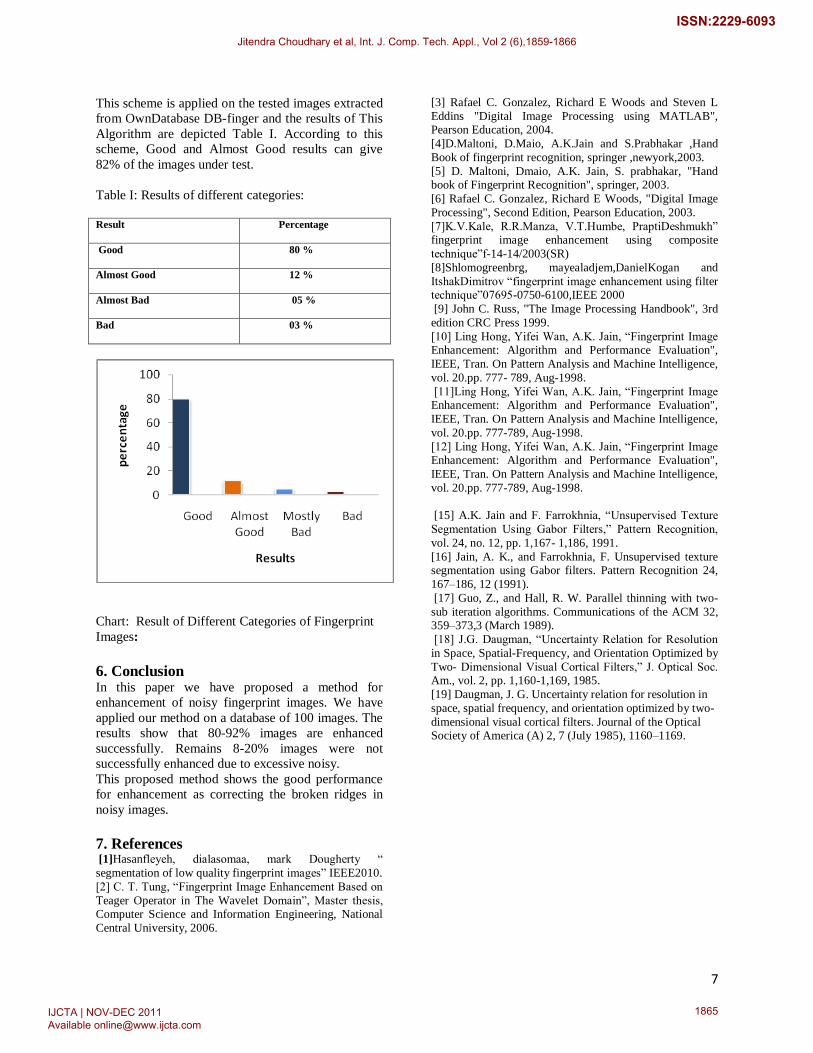
This scheme is applied on the tested images extracted
from OwnDatabase DB-finger and the results of This
Algorithm are depicted Table I. According to this
scheme, Good and Almost Good results can give
82% of the images under test.
Table I: Results of different categories:
Result
Percentage
Good
80 %
Almost Good
12 %
Almost Bad
05 %
Bad
03 %
Chart: Result of Different Categories of Fingerprint
Images:
6. Conclusion In this paper we have proposed a method for
enhancement of noisy fingerprint images. We have
applied our method on a database of 100 images. The
results show that 80-92% images are enhanced
successfully. Remains 8-20% images were not
successfully enhanced due to excessive noisy.
This proposed method shows the good performance
for enhancement as correcting the broken ridges in
noisy images.
7. References [1]Hasanfleyeh, dialasomaa, mark Dougherty “
segmentation of low quality fingerprint images” IEEE2010.
[2] C. T. Tung, “Fingerprint Image Enhancement Based on
Teager Operator in The Wavelet Domain”, Master thesis, Computer Science and Information Engineering, National
Central University, 2006.
[3] Rafael C. Gonzalez, Richard E Woods and Steven L
Eddins "Digital Image Processing using MATLAB", Pearson Education, 2004.
[4]D.Maltoni, D.Maio, A.K.Jain and S.Prabhakar ,Hand
Book of fingerprint recognition, springer ,newyork,2003.
[5] D. Maltoni, Dmaio, A.K. Jain, S. prabhakar, "Hand book of Fingerprint Recognition", springer, 2003.
[6] Rafael C. Gonzalez, Richard E Woods, "Digital Image
Processing", Second Edition, Pearson Education, 2003.
[7]K.V.Kale, R.R.Manza, V.T.Humbe, PraptiDeshmukh” fingerprint image enhancement using composite
technique”f-14-14/2003(SR)
[8]Shlomogreenbrg, mayealadjem,DanielKogan and
ItshakDimitrov “fingerprint image enhancement using filter technique”07695-0750-6100,IEEE 2000
[9] John C. Russ, "The Image Processing Handbook", 3rd
edition CRC Press 1999.
[10] Ling Hong, Yifei Wan, A.K. Jain, “Fingerprint Image Enhancement: Algorithm and Performance Evaluation",
IEEE, Tran. On Pattern Analysis and Machine Intelligence,
vol. 20.pp. 777- 789, Aug-1998.
[11]Ling Hong, Yifei Wan, A.K. Jain, “Fingerprint Image Enhancement: Algorithm and Performance Evaluation",
IEEE, Tran. On Pattern Analysis and Machine Intelligence,
vol. 20.pp. 777-789, Aug-1998.
[12] Ling Hong, Yifei Wan, A.K. Jain, “Fingerprint Image Enhancement: Algorithm and Performance Evaluation",
IEEE, Tran. On Pattern Analysis and Machine Intelligence,
vol. 20.pp. 777-789, Aug-1998.
[13]K. Karu and A.K. Jain, “Fingerprint Classification,” Pattern Recognition, vol. 29no. 3, pp. 389-404, 1996.[14] Dwayne Phillips, "Image Processing in C", BPB Publications, Ist Indian edition 1995. [15] A.K. Jain and F. Farrokhnia, “Unsupervised Texture
Segmentation Using Gabor Filters,” Pattern Recognition,
vol. 24, no. 12, pp. 1,167- 1,186, 1991.
[16] Jain, A. K., and Farrokhnia, F. Unsupervised texture segmentation using Gabor filters. Pattern Recognition 24,
167–186, 12 (1991).
[17] Guo, Z., and Hall, R. W. Parallel thinning with two-
sub iteration algorithms. Communications of the ACM 32, 359–373,3 (March 1989).
[18] J.G. Daugman, “Uncertainty Relation for Resolution
in Space, Spatial-Frequency, and Orientation Optimized by
Two- Dimensional Visual Cortical Filters,” J. Optical Soc. Am., vol. 2, pp. 1,160-1,169, 1985.
[19] Daugman, J. G. Uncertainty relation for resolution in
space, spatial frequency, and orientation optimized by two-
dimensional visual cortical filters. Journal of the Optical
Society of America (A) 2, 7 (July 1985), 1160–1169.
Jitendra Choudhary et al, Int. J. Comp. Tech. Appl., Vol 2 (6),1859-1866
IJCTA | NOV-DEC 2011 Available [email protected]
1865
ISSN:2229-6093

8
Jitendra Choudhary et al, Int. J. Comp. Tech. Appl., Vol 2 (6),1859-1866
IJCTA | NOV-DEC 2011 Available [email protected]
1866
ISSN:2229-6093