a new generation humanoid robot...
TRANSCRIPT
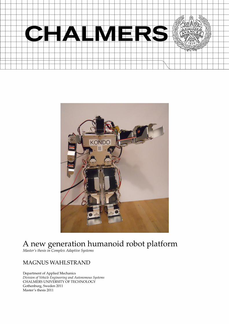
A new generation humanoid robot platformMaster’s thesis in Complex Adaptive Systems
MAGNUS WAHLSTRAND
Department of Applied MechanicsDivision of Vehicle Engineering and Autonomous SystemsCHALMERS UNIVERSITY OF TECHNOLOGYGothenburg, Sweden 2011Master’s thesis 2011

MASTER’S THESIS IN COMPLEX ADAPTIVE SYSTEMS
A new generation humanoid robot platform
MAGNUS WAHLSTRAND
Department of Applied MechanicsDivision of Vehicle Engineering and Autonomous Systems
CHALMERS UNIVERSITY OF TECHNOLOGY
Gothenburg, Sweden 2011
A new generation humanoid robot platformMAGNUS WAHLSTRAND
© MAGNUS WAHLSTRAND, 2011
Master’s thesis 2011Department of Applied MechanicsDivision of Vehicle Engineering and Autonomous SystemsChalmers University of TechnologySE-412 96 GothenburgSwedenTelephone: +46 (0)31-772 1000
Cover:Kondo, the humanoid robot that served as a basis for the project.
Printed by Reproservice, ChalmersGothenburg, Sweden 2011
ABSTRACT
There are many tasks that humans for different reasons are unwilling or unfit to do. Examples are, forinstance, dangerous tasks such as handling toxic waste or monotonous tasks, like working in assembly lines.The hope is that robots one day can do tasks like these for us. Even though a lot of progress has been made inrobotics in the last few decades, it is clear that a lot of work and research remains for this goal to be fulfilled.
This master thesis describes a process of upgrading Kondo, a small humanoid robot, from a basic robotwith no sensory capabilities to a more advanced robotic platform. The hope is that the improved platform canbe used to facilitate further research in several fields of robotics such as human-robot interaction, adaptivecontrol and evolutionary robotics.
In order to perform this upgrade, the servo controller of existing platform was replaced by a new pro-grammable servo controller. Furthermore, a sensor module with an accelerometer and distance sensors wasdesigned and added to the platform, giving Kondo sensory capabilities. To complete the system, a two partsoftware interface was created. This included a graphical user interface to directly control the robot and createmotion sequences and a Python class interface for prototyping and more advanced programs.
The resulting platform was tested in order to ensure that it fulfilled the objectives stipulated in the project.The tests included hardware testing, i.e. testing the actual motion of the robot and the communication betweento and from the electronic modules. The platform’s configurability was also tested by implementing threecommon robotic features, including automated fall recovery and wall avoidance.
The results of these tests indicate that the basic functionality of the new platform, such as walking andstanding, is rather robust. The speed of the developed gait however, can be improved. The platform isrelatively easy to extend and modify therefore can be used in education or in robotic research. A weaknessof the current platform is the number of connections needed to power and communicate with the electronicboards. Decreasing this number is something that could be worked on in future projects in order to increasethe robot’s autonomy.
Keywords: Humanoid robotics, Robotic research, Robot algorithm prototyping
i
ACKNOWLEDGEMENTS
First and foremost I would like to thank my supervisor, Krister Wolff, for letting me participate in thisproject and accepting to be my supervisor. Without his support and guidance this project would neversucceeded and I would not have learnt as much as I did.
I would also like thank my family for helping serving as moral support during the project and especiallyfor diligent proof-reading throughout the report writing process. Thank you also to Kajsa Greger and MatsStam for serving as semi-voluntary proof-readers and for enthusiastically cheering me on.
Furthermore, I owe a lot to many persons at ETA, Chalmers for helping me with the electronic design andmanufacturing and for drinking coffee with me. Special thanks goes to Robin Stephansen and Max Sikstromfor patiently answering my never ending questions and for their willingness to share there vast knowledge inelectronics. Many thanks also goes to Hans Odelius for being kind enough to let me use the equipment in theET-lab and helping me on very short notice.
Finally, I would like to thank Adrian, Frank and the rest of my friends. Without you I am nothing.
ii
CONTENTS
Abstract i
Acknowledgements ii
Contents iii
1 Introduction 11.1 Objectives . . . . . . . . . . . . . . . . . . . . . . . . . . . . . . . . . . . . . . . . . . . . . . . . . . . 11.2 Limitations . . . . . . . . . . . . . . . . . . . . . . . . . . . . . . . . . . . . . . . . . . . . . . . . . . . 21.3 Reading guidance . . . . . . . . . . . . . . . . . . . . . . . . . . . . . . . . . . . . . . . . . . . . . . . 2
2 Background 32.1 Autonomous robot . . . . . . . . . . . . . . . . . . . . . . . . . . . . . . . . . . . . . . . . . . . . . . 32.2 Robotic paradigms . . . . . . . . . . . . . . . . . . . . . . . . . . . . . . . . . . . . . . . . . . . . . . 32.3 Robotic motion . . . . . . . . . . . . . . . . . . . . . . . . . . . . . . . . . . . . . . . . . . . . . . . . 42.4 Locomotion in humanoid robotics . . . . . . . . . . . . . . . . . . . . . . . . . . . . . . . . . . . . . 42.5 Sensors . . . . . . . . . . . . . . . . . . . . . . . . . . . . . . . . . . . . . . . . . . . . . . . . . . . . . 52.6 Robot brain . . . . . . . . . . . . . . . . . . . . . . . . . . . . . . . . . . . . . . . . . . . . . . . . . . 7
3 Existing platform 83.1 Mechanical structure . . . . . . . . . . . . . . . . . . . . . . . . . . . . . . . . . . . . . . . . . . . . . 83.2 Servo motors . . . . . . . . . . . . . . . . . . . . . . . . . . . . . . . . . . . . . . . . . . . . . . . . . . 93.3 Electronics . . . . . . . . . . . . . . . . . . . . . . . . . . . . . . . . . . . . . . . . . . . . . . . . . . . 93.4 Software . . . . . . . . . . . . . . . . . . . . . . . . . . . . . . . . . . . . . . . . . . . . . . . . . . . . 10
4 Method 124.1 Hardware upgrade . . . . . . . . . . . . . . . . . . . . . . . . . . . . . . . . . . . . . . . . . . . . . . 124.2 Software development . . . . . . . . . . . . . . . . . . . . . . . . . . . . . . . . . . . . . . . . . . . . 124.3 Platform evaluation . . . . . . . . . . . . . . . . . . . . . . . . . . . . . . . . . . . . . . . . . . . . . . 124.4 Development tools . . . . . . . . . . . . . . . . . . . . . . . . . . . . . . . . . . . . . . . . . . . . . . 12
5 Design and implementation 135.1 Servo controller . . . . . . . . . . . . . . . . . . . . . . . . . . . . . . . . . . . . . . . . . . . . . . . . 135.2 Sensor module . . . . . . . . . . . . . . . . . . . . . . . . . . . . . . . . . . . . . . . . . . . . . . . . . 145.3 Python interface . . . . . . . . . . . . . . . . . . . . . . . . . . . . . . . . . . . . . . . . . . . . . . . . 15
6 Platform testing 176.1 Hardware testing . . . . . . . . . . . . . . . . . . . . . . . . . . . . . . . . . . . . . . . . . . . . . . . 176.2 Extendibility testing . . . . . . . . . . . . . . . . . . . . . . . . . . . . . . . . . . . . . . . . . . . . . 17
7 Results 197.1 Developed hardware . . . . . . . . . . . . . . . . . . . . . . . . . . . . . . . . . . . . . . . . . . . . . 197.2 Developed software . . . . . . . . . . . . . . . . . . . . . . . . . . . . . . . . . . . . . . . . . . . . . . 197.3 Test results . . . . . . . . . . . . . . . . . . . . . . . . . . . . . . . . . . . . . . . . . . . . . . . . . . . 20
8 Discussion 24
9 Conclusion and future work 259.1 Conclusion . . . . . . . . . . . . . . . . . . . . . . . . . . . . . . . . . . . . . . . . . . . . . . . . . . . 259.2 Future work . . . . . . . . . . . . . . . . . . . . . . . . . . . . . . . . . . . . . . . . . . . . . . . . . . 25
A ASC protocol 28
B ASM protocol 29
1 IntroductionThere are many tasks that humans do not like doing or are simply unfit to do for different reasons. This couldbe things that are dangerous, such as handling toxic waste or working in space, or tasks that are monotonous,such as working in assembly lines or harvesting cashew nuts.
In factories, industrial robots have been introduced to reduce the number of such tasks and at the sametime increasing speed, precision and efficiency of assembly lines. The first industrial robot, called the Unimate,was sold to General Motors in 1961. Since then the market has grown substantially and the total number ofindustrial robots are now about 1.2 million worldwide. While industrial robots have been used heavily inthe industry for almost half a century, the use of robots in the rest of society have been limited. Since thebeginning of the new millennium however, many service robots such as vacuum cleaning and lawn mowingrobots have been introduced to the market in parallel to robots used for military applications. In 2007, thenumber of service robots were about 5.5 million. This was expected to increase to 17 million until 2011 [1].
As the demand for robots in general has increased, there has also been an increased demand for moreadvanced robots that can perform more than just mundane, domestic duties. The hope is that these robotscan aid in solving many of problems we face in a modern society. For example the problem with an ageingpopulation, and that the working portion of the population is decreasing. Many of the robots being designedfor this purpose are of the type humanoid robots.
A humanoid robot is a robot whose overall structure is based on the human body. Humanoid robots aregenerally more complex, expensive and more difficult to control than their wheeled counterparts. In manysituations and environments however, humanoid robots have several advantages over traditional, wheeledrobots. Due to their structural similarity to humans, they are well suited to operate in human environments,use tools and operate vehicles designed for humans. For example, they are well adapted to climbing stairs.This makes humanoids suitable for tasks such as personal assistance, elderly care and other tasks in people’shomes. However, even though a lot of progress has been made both in general and humanoid robotics in thelast decade, it is clear that a lot of work and research has to be done before robots can be released to roam freein society.
At Chalmers university of technology, robotic research is being conducted by Adaptive systems researchgroup. Their main focus lies towards decision-making in autonomous agents, but robots are also used ineducation to teach engineering students about a multitude of topics such as microcontroller programming,signal treatment and the uncertainties when working with robotic systems in real life. One of the robots usedby group in the Humanoid robotics class is called Kondo KHR-1 and is a small humanoid robot.
This master thesis describes a process of upgrading Kondo, from a basic humanoid into a more advancedrobotic platform. The hope is that the improved platform will be used to facilitate further research in severalfields of robotics such as human-robot interaction (HRI), adaptive control and evolutionary robotics.
1.1 Objectives
The main objective of this project is to create a multi-level robotic platform that can be used in research ofrobotic topics as well as education. To accomplish this, the existing servo controller will be replaced by anew one that can be re-programmed if needed and extended with extra functionality. It is also relevant toexpand the existing robotic platform to include a sensory system. This would allow the robot a means ofdirect interaction with the environment and could also potentially serve to improve the robot’s motion controlsystem. On top of this, a high-level software interface shall be created in order to tie the different parts of therobot into a complete robotic system. This platform should be open for extension and modification.
These objectives can be divided into the following subobjectives:
1.1.1 SubobjectivesThe platform should be able to:
• execute basic motion, such as walking and turning.
• detect if it has fallen to the ground.
• get up from horizontal position.
1
• be controlled by users of different level of experience with robots.
• be easy to modify and extend.
To do this several things need to be created:
• a servo controller with at least 17 output channels.
• a sensor module with a distance sensor and accelerometer.
• a high level software interface for all modules.
• a graphical user interface for direct control of the robot.
1.2 Limitations
What is not within the scope of this project is to alter the physical features of the existing platform. The onlyactual hardware that will be replaced is the electronic modules on the back of the robot, while the actuatorsand the aluminium frame will be kept. This project does not aim at developing advanced robotic features,such as pattern recognition or a dynamic gait, but rather creating a general multi-functional robotic platformthat can later be extended and specialized if desired.
1.3 Reading guidance
This master thesis is organised in the following way:Chapter 2 gives an overview of robotics in general and discusses common robot architectures, actuators,
sensors and processors. In chapter 3, the existing robot that served as a basis for the project is presented.Chapter 4 describes the overall structure of the project; what has been done and why, and which tools thatwere used for the development. Chapter 5 describes the design process of the new servo controller, sensormodule and software interface. The tests that were performed to ensure that the platform fulfilled the projectgoals are described in chapter 6. The results from these tests, together with the final versions of the createdhardware and software are presented in chapter 7. Finally, chapter 8 discusses these results, while chapter 9concludes the project and presents possible future work with the platform.
2
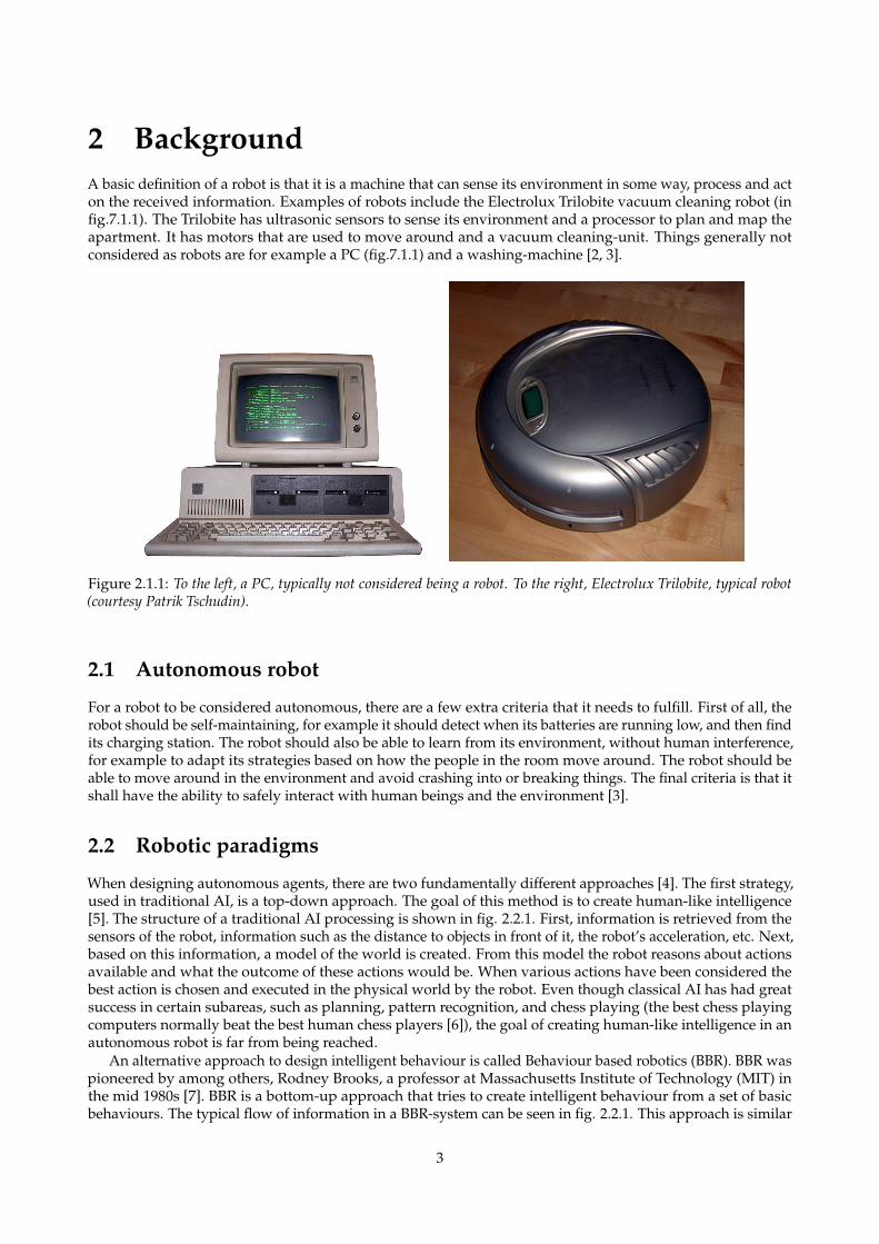
2 BackgroundA basic definition of a robot is that it is a machine that can sense its environment in some way, process and acton the received information. Examples of robots include the Electrolux Trilobite vacuum cleaning robot (infig.7.1.1). The Trilobite has ultrasonic sensors to sense its environment and a processor to plan and map theapartment. It has motors that are used to move around and a vacuum cleaning-unit. Things generally notconsidered as robots are for example a PC (fig.7.1.1) and a washing-machine [2, 3].
Figure 2.1.1: To the left, a PC, typically not considered being a robot. To the right, Electrolux Trilobite, typical robot(courtesy Patrik Tschudin).
2.1 Autonomous robot
For a robot to be considered autonomous, there are a few extra criteria that it needs to fulfill. First of all, therobot should be self-maintaining, for example it should detect when its batteries are running low, and then findits charging station. The robot should also be able to learn from its environment, without human interference,for example to adapt its strategies based on how the people in the room move around. The robot should beable to move around in the environment and avoid crashing into or breaking things. The final criteria is that itshall have the ability to safely interact with human beings and the environment [3].
2.2 Robotic paradigms
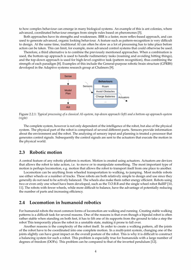
When designing autonomous agents, there are two fundamentally different approaches [4]. The first strategy,used in traditional AI, is a top-down approach. The goal of this method is to create human-like intelligence[5]. The structure of a traditional AI processing is shown in fig. 2.2.1. First, information is retrieved from thesensors of the robot, information such as the distance to objects in front of it, the robot’s acceleration, etc. Next,based on this information, a model of the world is created. From this model the robot reasons about actionsavailable and what the outcome of these actions would be. When various actions have been considered thebest action is chosen and executed in the physical world by the robot. Even though classical AI has had greatsuccess in certain subareas, such as planning, pattern recognition, and chess playing (the best chess playingcomputers normally beat the best human chess players [6]), the goal of creating human-like intelligence in anautonomous robot is far from being reached.
An alternative approach to design intelligent behaviour is called Behaviour based robotics (BBR). BBR waspioneered by among others, Rodney Brooks, a professor at Massachusetts Institute of Technology (MIT) inthe mid 1980s [7]. BBR is a bottom-up approach that tries to create intelligent behaviour from a set of basicbehaviours. The typical flow of information in a BBR-system can be seen in fig. 2.2.1. This approach is similar
3
to how complex behaviour can emerge in many biological systems. An example of this is ant colonies, whereadvanced, coordinated behaviour emerges from simple rules based on pheromones [5].
Both approaches have its strengths and weaknesses. BBR is a faster, more reflex-based approach, and canused to generate advanced, organic looking behaviour. A feature such as pattern-recognition is very difficultto design. At the same time, traditional AI can often be slow as a lot of processing has to take place beforeaction can be taken. This can limit, for example, more advanced control systems that could otherwise be used.
Therefore, a third alternative is to combine the previously mentioned approaches. When a combination isused, the bottom-up approach is used to handle rudimentary tasks (roaming and avoiding hitting things),and the top-down approach is used for high-level cognitive task (pattern recognition), thus combining thestrength of each paradigm [8]. Examples of this include the General-purpose robotic brain structure (GPRBS)developed in the Adaptive systems research group at Chalmers [9].
Avoid Obstacles
Roam
...
Charge Batteries
Behaviours
Actuators
Sense
Model
Plan
Act
Sensors
Figure 2.2.1: Typical processing of a classical AI-system, top-down approach (left) and a bottom-up approach-system(right)
The complete system, however is not only dependent of the intelligence of the robot, but also of the physicalsystem. The physical part of the robot is comprised of several different parts. Sensors provide informationabout the environment and the robot. The analysing of sensory input and planning is treated a processor thatgenerates control signals. Subsequently the control signals are sent to the actuators that execute the motion inthe physical world.
2.3 Robotic motion
A central feature of any robotic platform is motion. Motion is created using actuators. Actuators are devicesthat allows the robot to take action, i.e. to move or to manipulate something. The most important type ofmotion is perhaps locomotion, e.g. motion that allows the robot to transport itself from one place to another.
Locomotion can be anything from wheeled transportation to walking, to jumping. Most mobile robotsuse either wheels or a number of tracks. These robots are both relatively simple to design and use since theygenerally do not need to be actively balanced. The wheels also make them rather energy efficient. Robots usingtwo or even only one wheel have been developed, such as the T.O.B.B and the single wheel robot BallIP [10,11]. The robots with fewer wheels, while more difficult to balance, have the advantage of potentially reducingthe number of parts and increasing efficiency.
2.4 Locomotion in humanoid robotics
For humanoid robots the most common forms of locomotion are walking and running. Creating stable walkingpatterns is a difficult task for several reasons. One of the reasons is that even though a bipedal robot is oftenrather stable when standing on both feet, it has to lift one of its supports from the ground to take a step therobot This temporarily places the robot in a unstable state, making it prone to fall over.
Another reasons is the complexity of the robot itself. In order to create a walking pattern, all the jointsof the robot have to be coordinated into one complete motion. In a multi-joint system, changing one of thejoints slightly can have great impact on the overall posture of the robot. This is why it is difficult to constructa balancing system for such a robot. This problem is especially true for humanoids with a large number ofdegrees of freedom (DOFs). This problem can be compared to that of the inverted pendulum [12].
4
o_O
Support region
o_O
COM COM
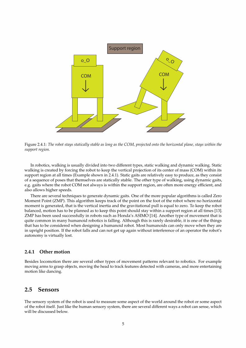
Figure 2.4.1: The robot stays statically stable as long as the COM, projected onto the horizontal plane, stays within thesupport region.
In robotics, walking is usually divided into two different types, static walking and dynamic walking. Staticwalking is created by forcing the robot to keep the vertical projection of its center of mass (COM) within itssupport region at all times (Example shown in 2.4.1). Static gaits are relatively easy to produce, as they consistof a sequence of poses that themselves are statically stable. The other type of walking, using dynamic gaits,e.g. gaits where the robot COM not always is within the support region, are often more energy efficient, andalso allows higher speeds.
There are several techniques to generate dynamic gaits. One of the more popular algorithms is called ZeroMoment Point (ZMP). This algorithm keeps track of the point on the foot of the robot where no horizontalmoment is generated, that is the vertical inertia and the gravitational pull is equal to zero. To keep the robotbalanced, motion has to be planned as to keep this point should stay within a support region at all times [13].ZMP has been used successfully in robots such as Honda’s ASIMO [14]. Another type of movement that isquite common in many humanoid robotics is falling. Although this is rarely desirable, it is one of the thingsthat has to be considered when designing a humanoid robot. Most humanoids can only move when they arein upright position. If the robot falls and can not get up again without interference of an operator the robot’sautonomy is virtually lost.
2.4.1 Other motion
Besides locomotion there are several other types of movement patterns relevant to robotics. For examplemoving arms to grasp objects, moving the head to track features detected with cameras, and more entertainingmotion like dancing.
2.5 Sensors
The sensory system of the robot is used to measure some aspect of the world around the robot or some aspectof the robot itself. Just like the human sensory system, there are several different ways a robot can sense, whichwill be discussed below.
5
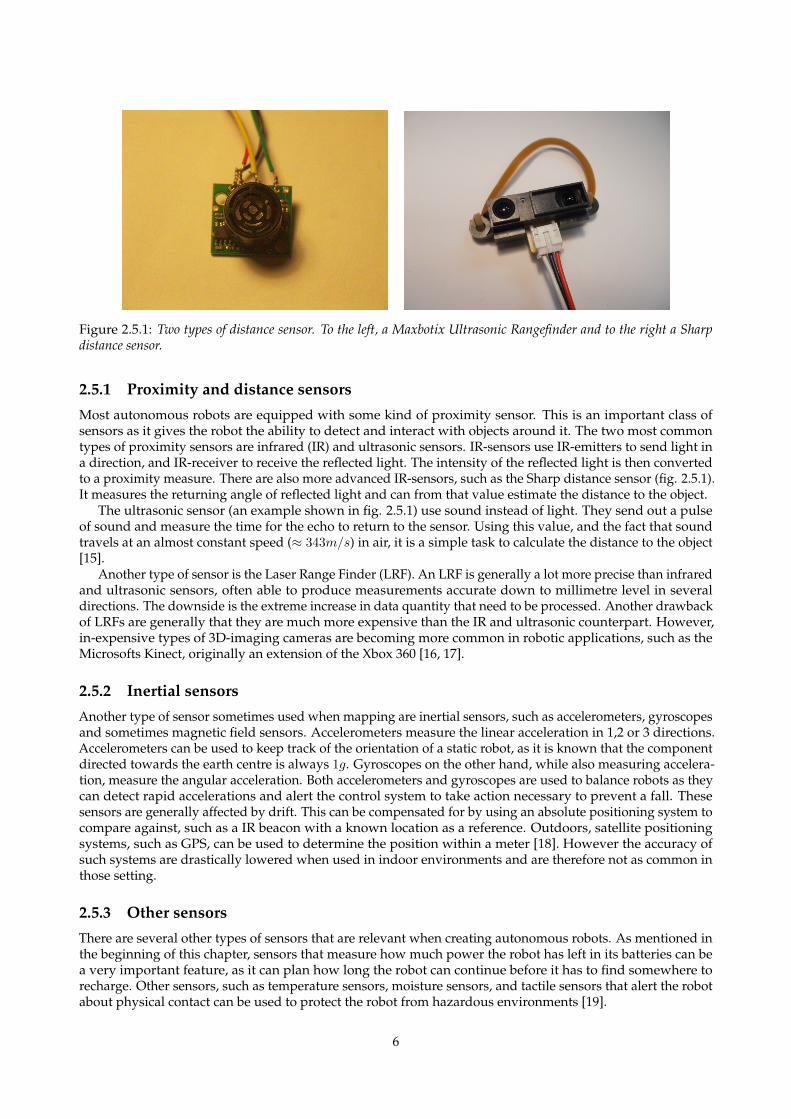
Figure 2.5.1: Two types of distance sensor. To the left, a Maxbotix Ultrasonic Rangefinder and to the right a Sharpdistance sensor.
2.5.1 Proximity and distance sensors
Most autonomous robots are equipped with some kind of proximity sensor. This is an important class ofsensors as it gives the robot the ability to detect and interact with objects around it. The two most commontypes of proximity sensors are infrared (IR) and ultrasonic sensors. IR-sensors use IR-emitters to send light ina direction, and IR-receiver to receive the reflected light. The intensity of the reflected light is then convertedto a proximity measure. There are also more advanced IR-sensors, such as the Sharp distance sensor (fig. 2.5.1).It measures the returning angle of reflected light and can from that value estimate the distance to the object.
The ultrasonic sensor (an example shown in fig. 2.5.1) use sound instead of light. They send out a pulseof sound and measure the time for the echo to return to the sensor. Using this value, and the fact that soundtravels at an almost constant speed (≈ 343m/s) in air, it is a simple task to calculate the distance to the object[15].
Another type of sensor is the Laser Range Finder (LRF). An LRF is generally a lot more precise than infraredand ultrasonic sensors, often able to produce measurements accurate down to millimetre level in severaldirections. The downside is the extreme increase in data quantity that need to be processed. Another drawbackof LRFs are generally that they are much more expensive than the IR and ultrasonic counterpart. However,in-expensive types of 3D-imaging cameras are becoming more common in robotic applications, such as theMicrosofts Kinect, originally an extension of the Xbox 360 [16, 17].
2.5.2 Inertial sensors
Another type of sensor sometimes used when mapping are inertial sensors, such as accelerometers, gyroscopesand sometimes magnetic field sensors. Accelerometers measure the linear acceleration in 1,2 or 3 directions.Accelerometers can be used to keep track of the orientation of a static robot, as it is known that the componentdirected towards the earth centre is always 1g. Gyroscopes on the other hand, while also measuring accelera-tion, measure the angular acceleration. Both accelerometers and gyroscopes are used to balance robots as theycan detect rapid accelerations and alert the control system to take action necessary to prevent a fall. Thesesensors are generally affected by drift. This can be compensated for by using an absolute positioning system tocompare against, such as a IR beacon with a known location as a reference. Outdoors, satellite positioningsystems, such as GPS, can be used to determine the position within a meter [18]. However the accuracy ofsuch systems are drastically lowered when used in indoor environments and are therefore not as common inthose setting.
2.5.3 Other sensors
There are several other types of sensors that are relevant when creating autonomous robots. As mentioned inthe beginning of this chapter, sensors that measure how much power the robot has left in its batteries can bea very important feature, as it can plan how long the robot can continue before it has to find somewhere torecharge. Other sensors, such as temperature sensors, moisture sensors, and tactile sensors that alert the robotabout physical contact can be used to protect the robot from hazardous environments [19].
6
2.6 Robot brain
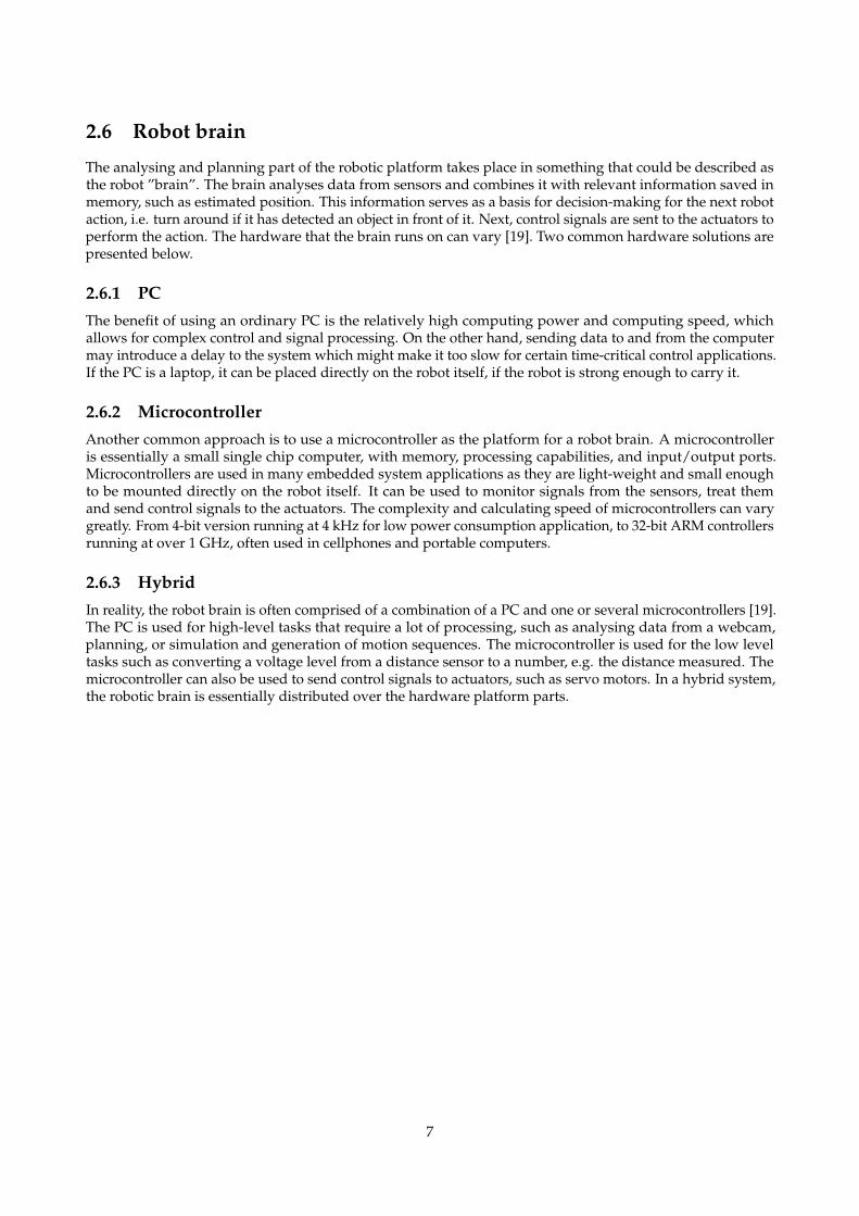
The analysing and planning part of the robotic platform takes place in something that could be described asthe robot ”brain”. The brain analyses data from sensors and combines it with relevant information saved inmemory, such as estimated position. This information serves as a basis for decision-making for the next robotaction, i.e. turn around if it has detected an object in front of it. Next, control signals are sent to the actuators toperform the action. The hardware that the brain runs on can vary [19]. Two common hardware solutions arepresented below.
2.6.1 PCThe benefit of using an ordinary PC is the relatively high computing power and computing speed, whichallows for complex control and signal processing. On the other hand, sending data to and from the computermay introduce a delay to the system which might make it too slow for certain time-critical control applications.If the PC is a laptop, it can be placed directly on the robot itself, if the robot is strong enough to carry it.
2.6.2 MicrocontrollerAnother common approach is to use a microcontroller as the platform for a robot brain. A microcontrolleris essentially a small single chip computer, with memory, processing capabilities, and input/output ports.Microcontrollers are used in many embedded system applications as they are light-weight and small enoughto be mounted directly on the robot itself. It can be used to monitor signals from the sensors, treat themand send control signals to the actuators. The complexity and calculating speed of microcontrollers can varygreatly. From 4-bit version running at 4 kHz for low power consumption application, to 32-bit ARM controllersrunning at over 1 GHz, often used in cellphones and portable computers.
2.6.3 HybridIn reality, the robot brain is often comprised of a combination of a PC and one or several microcontrollers [19].The PC is used for high-level tasks that require a lot of processing, such as analysing data from a webcam,planning, or simulation and generation of motion sequences. The microcontroller is used for the low leveltasks such as converting a voltage level from a distance sensor to a number, e.g. the distance measured. Themicrocontroller can also be used to send control signals to actuators, such as servo motors. In a hybrid system,the robotic brain is essentially distributed over the hardware platform parts.
7
3 Existing platform
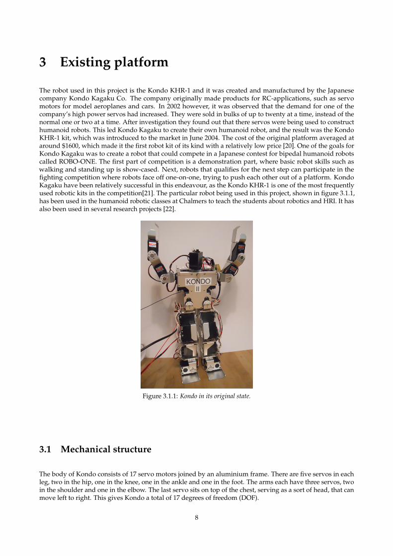
The robot used in this project is the Kondo KHR-1 and it was created and manufactured by the Japanesecompany Kondo Kagaku Co. The company originally made products for RC-applications, such as servomotors for model aeroplanes and cars. In 2002 however, it was observed that the demand for one of thecompany’s high power servos had increased. They were sold in bulks of up to twenty at a time, instead of thenormal one or two at a time. After investigation they found out that there servos were being used to constructhumanoid robots. This led Kondo Kagaku to create their own humanoid robot, and the result was the KondoKHR-1 kit, which was introduced to the market in June 2004. The cost of the original platform averaged ataround $1600, which made it the first robot kit of its kind with a relatively low price [20]. One of the goals forKondo Kagaku was to create a robot that could compete in a Japanese contest for bipedal humanoid robotscalled ROBO-ONE. The first part of competition is a demonstration part, where basic robot skills such aswalking and standing up is show-cased. Next, robots that qualifies for the next step can participate in thefighting competition where robots face off one-on-one, trying to push each other out of a platform. KondoKagaku have been relatively successful in this endeavour, as the Kondo KHR-1 is one of the most frequentlyused robotic kits in the competition[21]. The particular robot being used in this project, shown in figure 3.1.1,has been used in the humanoid robotic classes at Chalmers to teach the students about robotics and HRI. It hasalso been used in several research projects [22].
Figure 3.1.1: Kondo in its original state.
3.1 Mechanical structure
The body of Kondo consists of 17 servo motors joined by an aluminium frame. There are five servos in eachleg, two in the hip, one in the knee, one in the ankle and one in the foot. The arms each have three servos, twoin the shoulder and one in the elbow. The last servo sits on top of the chest, serving as a sort of head, that canmove left to right. This gives Kondo a total of 17 degrees of freedom (DOF).
8
3.2 Servo motors
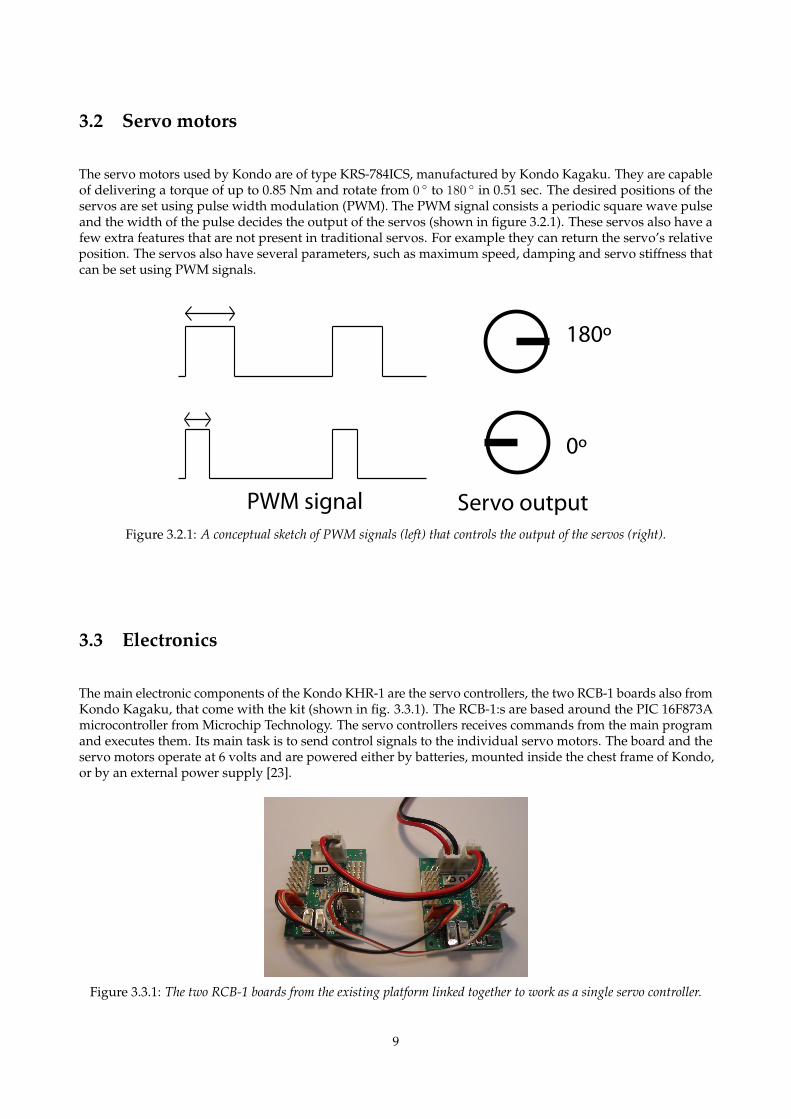
The servo motors used by Kondo are of type KRS-784ICS, manufactured by Kondo Kagaku. They are capableof delivering a torque of up to 0.85 Nm and rotate from 0 ◦ to 180 ◦ in 0.51 sec. The desired positions of theservos are set using pulse width modulation (PWM). The PWM signal consists a periodic square wave pulseand the width of the pulse decides the output of the servos (shown in figure 3.2.1). These servos also have afew extra features that are not present in traditional servos. For example they can return the servo’s relativeposition. The servos also have several parameters, such as maximum speed, damping and servo stiffness thatcan be set using PWM signals.
PWM signal Servo output
180º
0º
Figure 3.2.1: A conceptual sketch of PWM signals (left) that controls the output of the servos (right).
3.3 Electronics
The main electronic components of the Kondo KHR-1 are the servo controllers, the two RCB-1 boards also fromKondo Kagaku, that come with the kit (shown in fig. 3.3.1). The RCB-1:s are based around the PIC 16F873Amicrocontroller from Microchip Technology. The servo controllers receives commands from the main programand executes them. Its main task is to send control signals to the individual servo motors. The board and theservo motors operate at 6 volts and are powered either by batteries, mounted inside the chest frame of Kondo,or by an external power supply [23].
Figure 3.3.1: The two RCB-1 boards from the existing platform linked together to work as a single servo controller.
9
3.4 Software
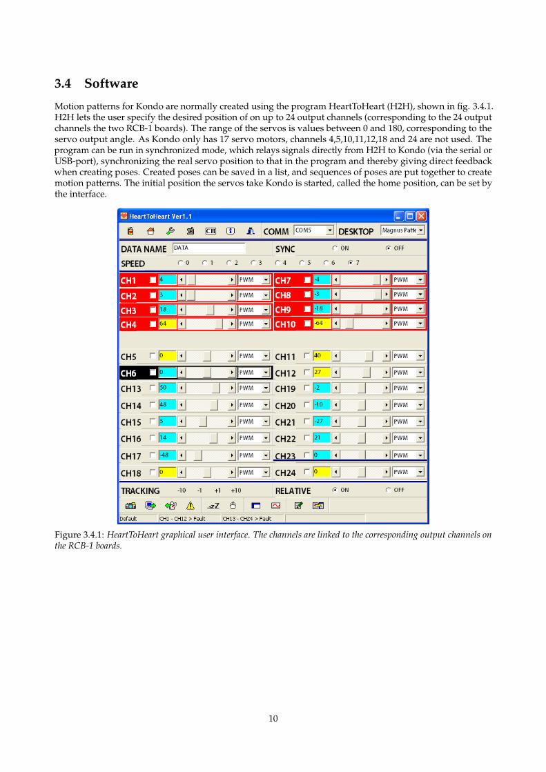
Motion patterns for Kondo are normally created using the program HeartToHeart (H2H), shown in fig. 3.4.1.H2H lets the user specify the desired position of on up to 24 output channels (corresponding to the 24 outputchannels the two RCB-1 boards). The range of the servos is values between 0 and 180, corresponding to theservo output angle. As Kondo only has 17 servo motors, channels 4,5,10,11,12,18 and 24 are not used. Theprogram can be run in synchronized mode, which relays signals directly from H2H to Kondo (via the serial orUSB-port), synchronizing the real servo position to that in the program and thereby giving direct feedbackwhen creating poses. Created poses can be saved in a list, and sequences of poses are put together to createmotion patterns. The initial position the servos take Kondo is started, called the home position, can be set bythe interface.
Figure 3.4.1: HeartToHeart graphical user interface. The channels are linked to the corresponding output channels onthe RCB-1 boards.
10
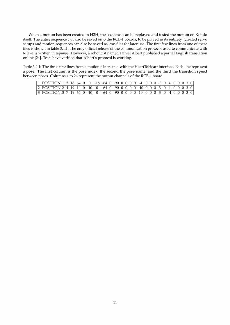
When a motion has been created in H2H, the sequence can be replayed and tested the motion on Kondoitself. The entire sequence can also be saved onto the RCB-1 boards, to be played in its entirety. Created servosetups and motion sequences can also be saved as .csv-files for later use. The first few lines from one of thesefiles is shown in table 3.4.1. The only official release of the communication protocol used to communicate withRCB-1 is written in Japanse. However, a roboticist named Daniel Albert published a partial English translationonline [24]. Tests have verified that Albert’s protocol is working.
Table 3.4.1: The three first lines from a motion file created with the HeartToHeart interface. Each line representa pose. The first column is the pose index, the second the pose name, and the third the transition speedbetween poses. Columns 4 to 24 represent the output channels of the RCB-1 board.
1 POSITION 1 5 18 64 0 0 -18 -64 0 -90 0 0 0 0 -4 0 0 0 -3 0 4 0 0 0 3 02 POSITION 2 4 19 14 0 -10 0 -64 0 -90 0 0 0 0 -40 0 0 0 3 0 4 0 0 0 3 03 POSITION 3 7 19 64 0 -10 0 -64 0 -90 0 0 0 0 10 0 0 0 3 0 -4 0 0 0 3 0
11
4 MethodThe work of creating the platform itself can be divided into three main parts: (1) upgrading and extending thehardware of the robot, (2) developing the software interface, and (3) platform testing and evaluation. The firsttwo parts were developed in parallel, while the evaluation took place after the platform had been completed.
4.1 Hardware upgrade
Preceding the development of the new hardware, the existing platform was evaluated. The RCB-1 boards andthe servos were mapped using oscilloscopes and signal generators and the translated communication protocol(section 3.4) was tested using RealTerm (see section 4.4).
While the existing Kondo performs well in many situations, there are a few situations when the designdoes not fulfill the needs of a research platform. In its original setup the servo controller is not made for usermodification. For the platform to be usable both in research and educational settings, it should be adaptableand modifiable. For these reasons, a new servo controller had to be developed so that it fulfills these demands.An important aspect was that the new servo controller could be reprogrammed if needed and extended withextra functionality.
Another weakness of the existing platform is that it does not have any sensory capabilities. This limits therobots capabilities of interacting with and adapting to the environment. To address this, a sensor board wasdesigned as to help increase the autonomy of the robot. This was also important for creating the fall recoveryprocedure. To achieve the goal of creating a platform that can be used to create autonomous behaviour.
4.2 Software development
In the original setup, motion is created using the H2H interface. The interface simplifies the creation of suchmotion by giving the user direct control over the servo output. It is therefore desirable to create a similarimplementation for the re-designed electronic system. While simplicity of the control is important, creatingmore advanced algorithms using the GUI is not possible. As one of the goals of this project is to be able toprototype and test robotic algorithms rapidly, it is of interest to create an environment where control of therobot can be scripted, modularised and reused. For this purpose, a class interface was created. The interfaceshould serve the purpose of bringing the different parts of the system (servo controller, sensor module andhost PC) into one complete system.
4.3 Platform evaluation
Once the platform is set up and electronic modules and software interface created, extensive testing should beperformed in order to ensure that the system satisfied the project specifications. It is therefore relevant to testthe hardware and how easy the platform is to extend and modify.
4.4 Development tools
Circuit design were performed in the EAGLE, a program used to create electronic schematics and to CADcorresponding PCB layouts. PCBs from these blue prints were created in the lab. To test and develop thePC-to-Circuit-communication systems, the terminal program RealTerm was used to send and receive bytedata over the serial port [25].
All of the programming in the project was performed in the Eclipse IDE. The programs for the mi-crocontrollers were written in C in Eclipse extended with the AVR Eclipse Plugin, and transferred to themicrocontrollers using a USBtinyISP-programmer [26].
For the developed software interface, created in Python 2.6, the Eclipse-plugin PyDev was used [27]. Themain external Python libraries used were pySerial, used to send and receive byte data over the serial port,wxPython used to create the GUI for the ASI, and OpenCV, used in the evaluation stage to implement thefacial detection and tracking [28, 29, 30].
12
5 Design and implementation
This chapter discusses the design and implementation of the electronic and software systems of the robotplatform.
5.1 Servo controller
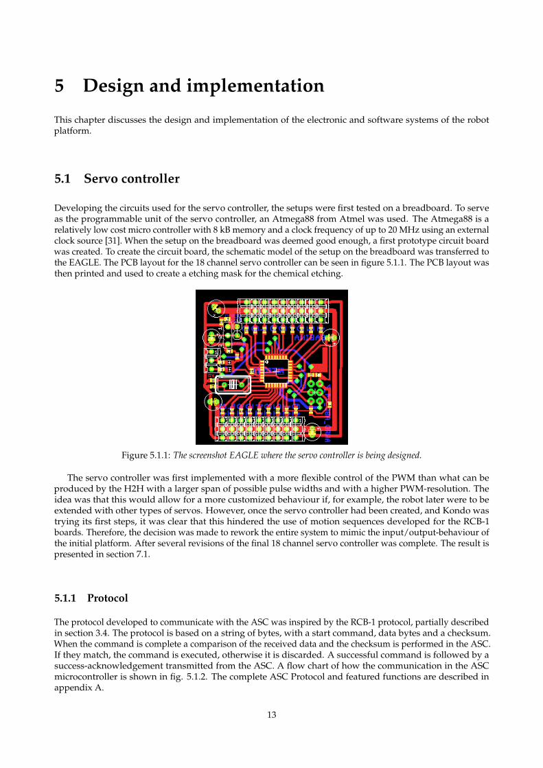
Developing the circuits used for the servo controller, the setups were first tested on a breadboard. To serveas the programmable unit of the servo controller, an Atmega88 from Atmel was used. The Atmega88 is arelatively low cost micro controller with 8 kB memory and a clock frequency of up to 20 MHz using an externalclock source [31]. When the setup on the breadboard was deemed good enough, a first prototype circuit boardwas created. To create the circuit board, the schematic model of the setup on the breadboard was transferred tothe EAGLE. The PCB layout for the 18 channel servo controller can be seen in figure 5.1.1. The PCB layout wasthen printed and used to create a etching mask for the chemical etching.
Figure 5.1.1: The screenshot EAGLE where the servo controller is being designed.
The servo controller was first implemented with a more flexible control of the PWM than what can beproduced by the H2H with a larger span of possible pulse widths and with a higher PWM-resolution. Theidea was that this would allow for a more customized behaviour if, for example, the robot later were to beextended with other types of servos. However, once the servo controller had been created, and Kondo wastrying its first steps, it was clear that this hindered the use of motion sequences developed for the RCB-1boards. Therefore, the decision was made to rework the entire system to mimic the input/output-behaviour ofthe initial platform. After several revisions of the final 18 channel servo controller was complete. The result ispresented in section 7.1.
5.1.1 Protocol
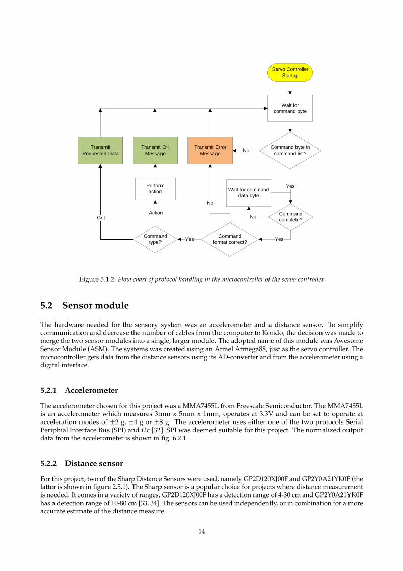
The protocol developed to communicate with the ASC was inspired by the RCB-1 protocol, partially describedin section 3.4. The protocol is based on a string of bytes, with a start command, data bytes and a checksum.When the command is complete a comparison of the received data and the checksum is performed in the ASC.If they match, the command is executed, otherwise it is discarded. A successful command is followed by asuccess-acknowledgement transmitted from the ASC. A flow chart of how the communication in the ASCmicrocontroller is shown in fig. 5.1.2. The complete ASC Protocol and featured functions are described inappendix A.
13
Command byte in
command list?
Wait for
command byte
Transmit Error
MessageNo
Wait for command
data byte
Command
complete?No
Command
format correct?Yes
No
Command
type?Yes
Transmit
Requested Data
Perform
action
Action
Transmit OK
Message
Get
Yes
Servo Controller
Startup
Figure 5.1.2: Flow chart of protocol handling in the microcontroller of the servo controller
5.2 Sensor module
The hardware needed for the sensory system was an accelerometer and a distance sensor. To simplifycommunication and decrease the number of cables from the computer to Kondo, the decision was made tomerge the two sensor modules into a single, larger module. The adopted name of this module was AwesomeSensor Module (ASM). The systems was created using an Atmel Atmega88, just as the servo controller. Themicrocontroller gets data from the distance sensors using its AD-converter and from the accelerometer using adigital interface.
5.2.1 Accelerometer
The accelerometer chosen for this project was a MMA7455L from Freescale Semiconductor. The MMA7455Lis an accelerometer which measures 3mm x 5mm x 1mm, operates at 3.3V and can be set to operate atacceleration modes of ±2 g, ±4 g or ±8 g. The accelerometer uses either one of the two protocols SerialPeriphial Interface Bus (SPI) and i2c [32]. SPI was deemed suitable for this project. The normalized outputdata from the accelerometer is shown in fig. 6.2.1
5.2.2 Distance sensor
For this project, two of the Sharp Distance Sensors were used, namely GP2D120XJ00F and GP2Y0A21YK0F (thelatter is shown in figure 2.5.1). The Sharp sensor is a popular choice for projects where distance measurementis needed. It comes in a variety of ranges, GP2D120XJ00F has a detection range of 4-30 cm and GP2Y0A21YK0Fhas a detection range of 10-80 cm [33, 34]. The sensors can be used independently, or in combination for a moreaccurate estimate of the distance measure.
14
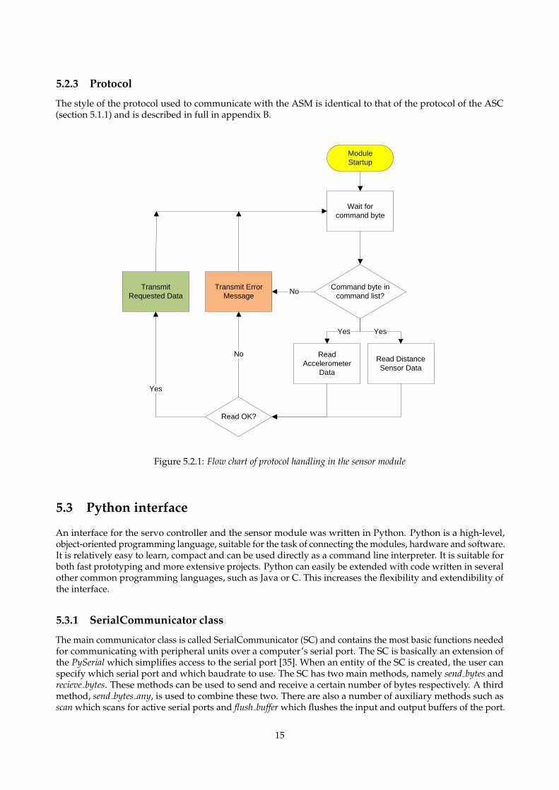
5.2.3 Protocol
The style of the protocol used to communicate with the ASM is identical to that of the protocol of the ASC(section 5.1.1) and is described in full in appendix B.
Command byte in
command list?
Wait for
command byte
Transmit Error
Message No
Transmit
Requested Data
Module
Startup
Read
Accelerometer
Data
Read Distance
Sensor Data
Yes
Read OK?
Yes
No
Yes
Figure 5.2.1: Flow chart of protocol handling in the sensor module
5.3 Python interface
An interface for the servo controller and the sensor module was written in Python. Python is a high-level,object-oriented programming language, suitable for the task of connecting the modules, hardware and software.It is relatively easy to learn, compact and can be used directly as a command line interpreter. It is suitable forboth fast prototyping and more extensive projects. Python can easily be extended with code written in severalother common programming languages, such as Java or C. This increases the flexibility and extendibility ofthe interface.
5.3.1 SerialCommunicator class
The main communicator class is called SerialCommunicator (SC) and contains the most basic functions neededfor communicating with peripheral units over a computer’s serial port. The SC is basically an extension ofthe PySerial which simplifies access to the serial port [35]. When an entity of the SC is created, the user canspecify which serial port and which baudrate to use. The SC has two main methods, namely send bytes andrecieve bytes. These methods can be used to send and receive a certain number of bytes respectively. A thirdmethod, send bytes any, is used to combine these two. There are also a number of auxiliary methods such asscan which scans for active serial ports and flush buffer which flushes the input and output buffers of the port.
15
5.3.2 ServoControllerCommunicator classThe ServoControllerCommunicator (SCC) implements the SC-class and extends it to form a link to theAwesome Servo Controller. The SCC lets the user send any of the functions available in the ASC, such asset servo position, get servo position and set speed. SCC also controls the error handling, and resubmits anycommand until it gets an success-acknowledgement together with the correct checksum from the servocontroller, or a maximum number of attempts have been reached. The complete command list can be found inthe appendix A.
5.3.3 SensorModuleCommunicator classThis module is another implementation of the SC-class. It was created with the intent of serving as an interfaceto the ASM. The main methods of this module are thus get acceleration x, get acceleration y, get acceleration z andget distance 1,get distance 2. Just as the SCC, the SMC has built-in error handling systems for the communication.The complete command list can be found in the appendix B.
5.3.4 Kondo classThe Kondo class is the highest level class created in the project. It is mainly made up by a SensorModuleCom-municator object and a ServoControllerCommunicator object to allow control over both the ASC and the ASM.The Kondo-class keeps track of the low level information such as what pose the robot is currently in and whichspeed the servo controller is set to, but also higher level information such as which foot is foward, or whichsequence of motion that is needed before Kondo can start executing one of the higher level motion patterns.The Kondo interface includes several motion functions such as walk, turn left and turn right, that simplifiesthe control of the robot’s motion. It also features information methods such as has fallen, and is standing. Thisclass also has methods for loading sequences of motions for the Kondo and storing them, for future use. Forexample load motion(’fast walk.ss’,’walk2’) can be executed by run motion(’walk2’).
5.3.5 Awesome servo interfaceA GUI called the Awesome Servo Interface (ASI) was created on top of the SCC-class and has similar function-ality to H2H. ASI uses wxPython which is a wrapper for the wxWidget toolkit, often used in Python to creategraphical interfaces, to display the graphical components.
16
6 Platform testingAfter the basic functionality of the robot had been implemented, further test were carried out in order to makesure that the platform fulfilled the objectives in section 1.1. This chapter describes the process of testing thenew system and its parts. The test result are presented in chapter 7.
6.1 Hardware testing
An important aspect of this project is that the basic functionality, such as motion and communication betweenthe separate parts of the research platform, work in a satisfactory manner. The developed hardware weretested to ensure that the developed motion (i.e. the walking, the fall recovery) and the communication worked.
6.1.1 Test of gait
To test the developed gait, the robot was made to walk a distance of 30 centimetres on a flat hardwood floor.The total time and the number of falls were recorded. If the robot fell during the course, time was stopped andit was recovered to upright position and no penalty was given. The test was run 20 times and the result can beseen in table 7.3.1.
6.1.2 Standing up-test
As stated earlier, a working fall recovery procedure is very important to increase the level of autonomy ofthe robot. When the robot has detected a fall (further described in 7.3.2) it has to stand up. Two aspects ofthe standing up-procedure were tested. The first one aspect is how reliable the procedure is, that is, does itmanage to get up from lying position or does it fall down again. This is important as extra falls could putunnecessary strain on the robot, and thus wearing it out more easily and also consuming more time.
6.1.3 Communication test
To measure the reliability of the communication between the PC and the servo controller, and the PC and thesensor module, another test was designed. The test was performed by taking operations from each modulesrespective command-list, and send these commands to the modules. An error is defined as when a command issent and the answer bytes are incorrect or not returned at all. When an error occurs, the interface automaticallyresends the data (up to 10 times). Fatal error is defined as the command has not been completed after themaximum number of resends. The result of the test is shown in section 7.3.1.
6.2 Extendibility testing
Another important aspect of this project was to test the developed robotics platform to see whether it actuallymade prototyping easier. To test this, three different test cases were introduced and evaluated. The first oneis called Fall recovery and tested the servo controller in combination with the accelerometer. The second testwas called Face detection and tracking to test the webcam and the third one Wall avoidance and uses one of thedistance sensors.
6.2.1 Wall avoidance
A common requirement in robotic application is obstacle avoidance, and in particular wall avoidance. This isimportant because if the robot walks into something, it runs the risk of damaging itself or the object. This testaims at giving Kondo this ability. The robot is to walk forward in a straight line until it finds a wall, then turnaway from said wall, and continue walking. The results of the test case is presented in section 7.3.2.
17
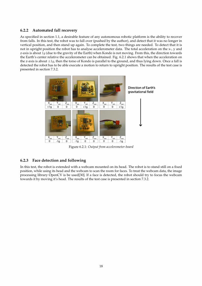
6.2.2 Automated fall recoveryAs specified in section 1.1, a desirable feature of any autonomous robotic platform is the ability to recoverfrom falls. In this test, the robot was to fall over (pushed by the author), and detect that it was no longer invertical position, and then stand up again. To complete the test, two things are needed. To detect that it isnot in upright position the robot has to analyse accelerometer data. The total acceleration on the x-, y andz-axis is about 1g (due to the gravity of the Earth) when Kondo is not moving. From this, the direction towardsthe Earth’s center relative the accelerometer can be obtained. Fig. 6.2.1 shows that when the acceleration onthe z-axis is about ±1g, then the torso of Kondo is parallel to the ground, and thus lying down. Once a fall isdetected the robot has to be able execute a motion to return to upright position. The results of the test case ispresented in section 7.3.2.
Figure 6.2.1: Output from accelerometer-board
6.2.3 Face detection and followingIn this test, the robot is extended with a webcam mounted on its head. The robot is to stand still on a fixedposition, while using its head and the webcam to scan the room for faces. To treat the webcam data, the imageprocessing library OpenCV is be used[30]. If a face is detected, the robot should try to focus the webcamtowards it by moving it’s head. The results of the test case is presented in section 7.3.2.
18
7 ResultsIn this chapter, an overview of the created hardware modules and the software interface is presented togetherwith the results of the tests described in chapter 6.
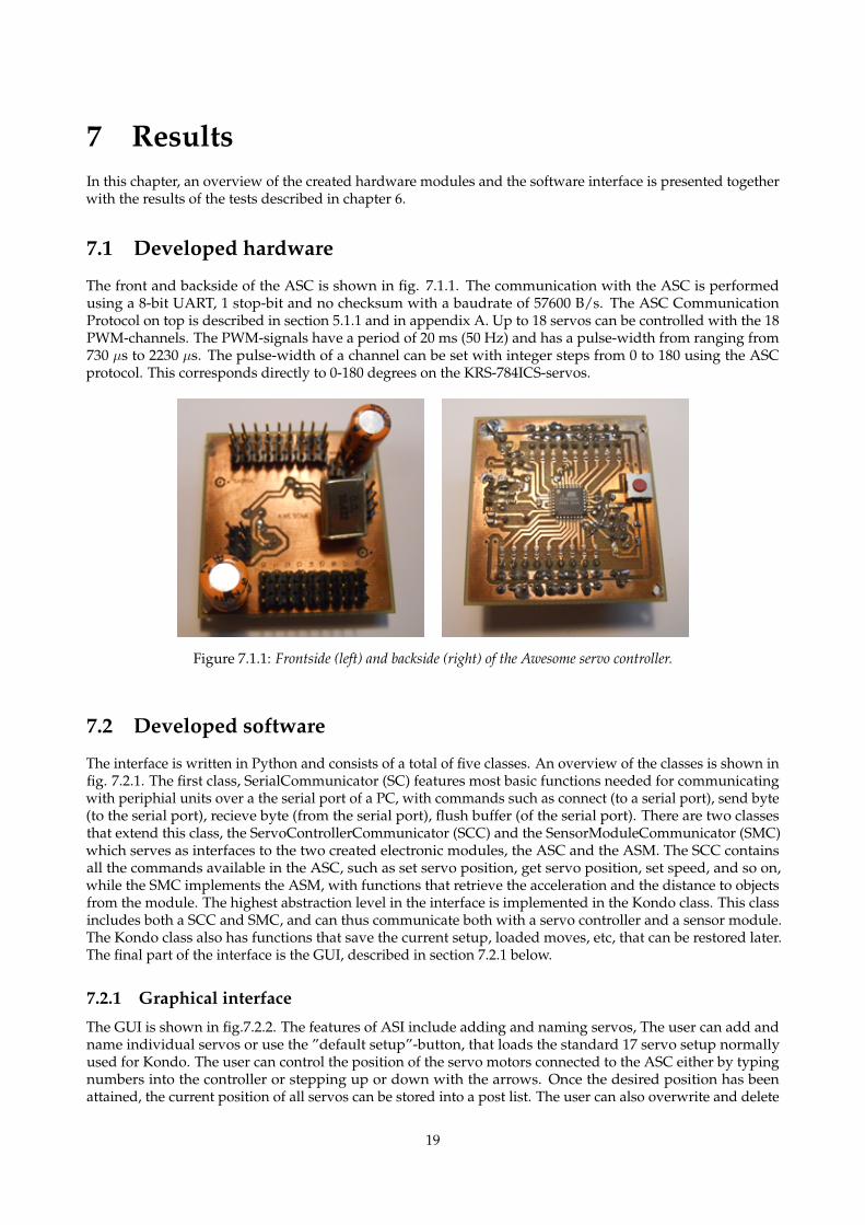
7.1 Developed hardware
The front and backside of the ASC is shown in fig. 7.1.1. The communication with the ASC is performedusing a 8-bit UART, 1 stop-bit and no checksum with a baudrate of 57600 B/s. The ASC CommunicationProtocol on top is described in section 5.1.1 and in appendix A. Up to 18 servos can be controlled with the 18PWM-channels. The PWM-signals have a period of 20 ms (50 Hz) and has a pulse-width from ranging from730 µs to 2230 µs. The pulse-width of a channel can be set with integer steps from 0 to 180 using the ASCprotocol. This corresponds directly to 0-180 degrees on the KRS-784ICS-servos.
Figure 7.1.1: Frontside (left) and backside (right) of the Awesome servo controller.
7.2 Developed software
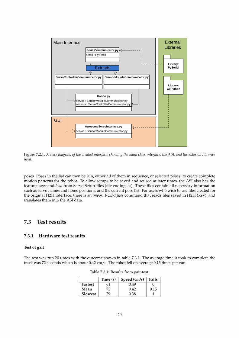
The interface is written in Python and consists of a total of five classes. An overview of the classes is shown infig. 7.2.1. The first class, SerialCommunicator (SC) features most basic functions needed for communicatingwith periphial units over a the serial port of a PC, with commands such as connect (to a serial port), send byte(to the serial port), recieve byte (from the serial port), flush buffer (of the serial port). There are two classesthat extend this class, the ServoControllerCommunicator (SCC) and the SensorModuleCommunicator (SMC)which serves as interfaces to the two created electronic modules, the ASC and the ASM. The SCC containsall the commands available in the ASC, such as set servo position, get servo position, set speed, and so on,while the SMC implements the ASM, with functions that retrieve the acceleration and the distance to objectsfrom the module. The highest abstraction level in the interface is implemented in the Kondo class. This classincludes both a SCC and SMC, and can thus communicate both with a servo controller and a sensor module.The Kondo class also has functions that save the current setup, loaded moves, etc, that can be restored later.The final part of the interface is the GUI, described in section 7.2.1 below.
7.2.1 Graphical interface
The GUI is shown in fig.7.2.2. The features of ASI include adding and naming servos, The user can add andname individual servos or use the ”default setup”-button, that loads the standard 17 servo setup normallyused for Kondo. The user can control the position of the servo motors connected to the ASC either by typingnumbers into the controller or stepping up or down with the arrows. Once the desired position has beenattained, the current position of all servos can be stored into a post list. The user can also overwrite and delete
19
serial : PySerial
SerialCommunicator.py
SensorModuleCommunicator.pyServoControllerCommunicator.py
servos : SensorModuleCommunicator.py
sensors : ServoControllerCommunicator.py
Kondo.py
Library:
PySerial
servos : SensorModuleCommunicator.py
AwesomeServoInterface.py
External
LibrariesMain Interface
GUI
Library:
wxPython
Extends
Figure 7.2.1: A class diagram of the created interface, showing the main class interface, the ASI, and the external librariesused.
poses. Poses in the list can then be run, either all of them in sequence, or selected poses, to create completemotion patterns for the robot. To allow setups to be saved and reused at later times, the ASI also has thefeatures save and load from Servo Setup-files (file ending .ss). These files contain all necessary informationsuch as servo names and home positions, and the current pose list. For users who wish to use files created forthe original H2H interface, there is an import RCB-1 files command that reads files saved in H2H (.csv), andtranslates them into the ASI data.
7.3 Test results
7.3.1 Hardware test results
Test of gait
The test was run 20 times with the outcome shown in table 7.3.1. The average time it took to complete thetrack was 72 seconds which is about 0.42 cm/s. The robot fell on average 0.15 times per run.
Table 7.3.1: Results from gait-test.
Time (s) Speed (cm/s) FallsFastest 61 0.49 0Mean 72 0.42 0.15Slowest 79 0.38 1
20
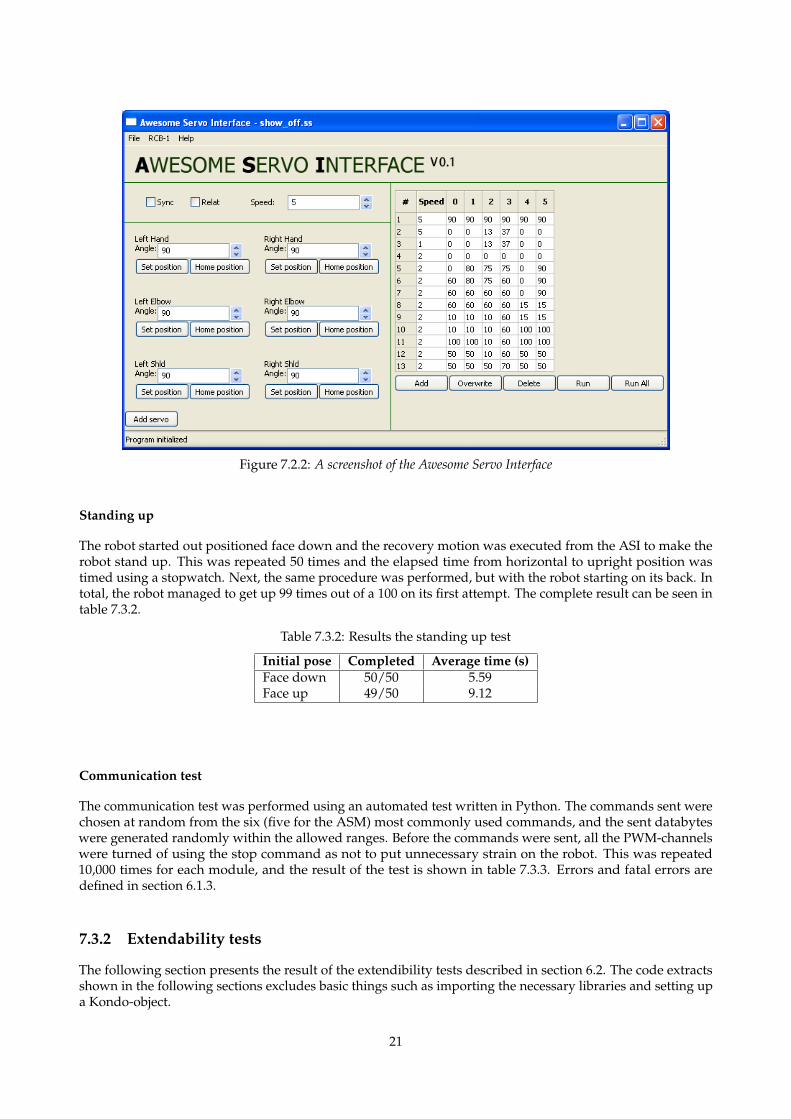
Figure 7.2.2: A screenshot of the Awesome Servo Interface
Standing up
The robot started out positioned face down and the recovery motion was executed from the ASI to make therobot stand up. This was repeated 50 times and the elapsed time from horizontal to upright position wastimed using a stopwatch. Next, the same procedure was performed, but with the robot starting on its back. Intotal, the robot managed to get up 99 times out of a 100 on its first attempt. The complete result can be seen intable 7.3.2.
Table 7.3.2: Results the standing up test
Initial pose Completed Average time (s)Face down 50/50 5.59Face up 49/50 9.12
Communication test
The communication test was performed using an automated test written in Python. The commands sent werechosen at random from the six (five for the ASM) most commonly used commands, and the sent databyteswere generated randomly within the allowed ranges. Before the commands were sent, all the PWM-channelswere turned of using the stop command as not to put unnecessary strain on the robot. This was repeated10,000 times for each module, and the result of the test is shown in table 7.3.3. Errors and fatal errors aredefined in section 6.1.3.
7.3.2 Extendability tests
The following section presents the result of the extendibility tests described in section 6.2. The code extractsshown in the following sections excludes basic things such as importing the necessary libraries and setting upa Kondo-object.
21
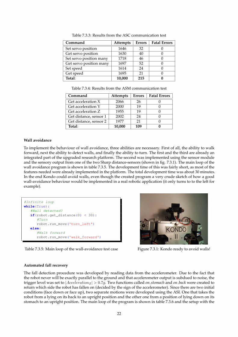
Table 7.3.3: Results from the ASC communication test
Command Attempts Errors Fatal ErrorsSet servo position 1646 32 0Get servo position 1630 40 0Set servo position many 1718 46 0Get servo position many 1697 52 0Set speed 1614 24 0Get speed 1695 21 0Total: 10,000 215 0
Table 7.3.4: Results from the ASM communication test
Command Attempts Errors Fatal ErrorsGet acceleration X 2066 26 0Get acceleration Y 2000 19 0Get acceleration Z 1955 19 0Get distance, sensor 1 2002 24 0Get distance, sensor 2 1977 21 0Total: 10,000 109 0
Wall avoidance
To implement the behaviour of wall avoidance, three abilities are necessary. First of all, the ability to walkforward, next the ability to detect walls, and finally the ability to turn. The first and the third are already anintegrated part of the upgraded research platform. The second was implemented using the sensor moduleand the sensory output from one of the two Sharp distance-sensors (shown in fig. 7.3.1). The main loop of thewall avoidance program is shown in table 7.3.5. The development time of this was fairly short, as most of thefeatures needed were already implemented in the platform. The total development time was about 30 minutes.In the end Kondo could avoid walls, even though the created program a very crude sketch of how a goodwall-avoidance behaviour would be implemented in a real robotic application (it only turns to to the left forexample).
#Infinite loopwhile(True):
#Wall detected?if(robot.get_distance(0) < 30):
#Turnrobot.run_move('turn_left')
else:#Walk forwardrobot.run_move('walk_forward')
Table 7.3.5: Main loop of the wall-avoidance test case Figure 7.3.1: Kondo ready to avoid walls!
Automated fall recovery
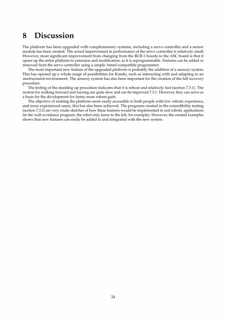
The fall detection procedure was developed by reading data from the accelerometer. Due to the fact thatthe robot never will be exactly parallel to the ground and that accelerometer output is subdued to noise, thetrigger level was set to |AccelerationZ | > 0.7g. Two functions called on stomach and on back were created toreturn which side the robot has fallen on (decided by the sign of the accelerometer). Since there are two initialconditions (face down or face up), two separate motions were developed using the ASI. One that takes therobot from a lying on its back to an upright position and the other one from a position of lying down on itsstomach to an upright position. The main loop of the program is shown in table 7.3.6 and the setup with the
22
accelerometer on the back of Kondo is shown in fig 7.3.2.The development time for the fall recovery ability was about 3 hours. Most of the time was needed to
create the two standing up-procedures.
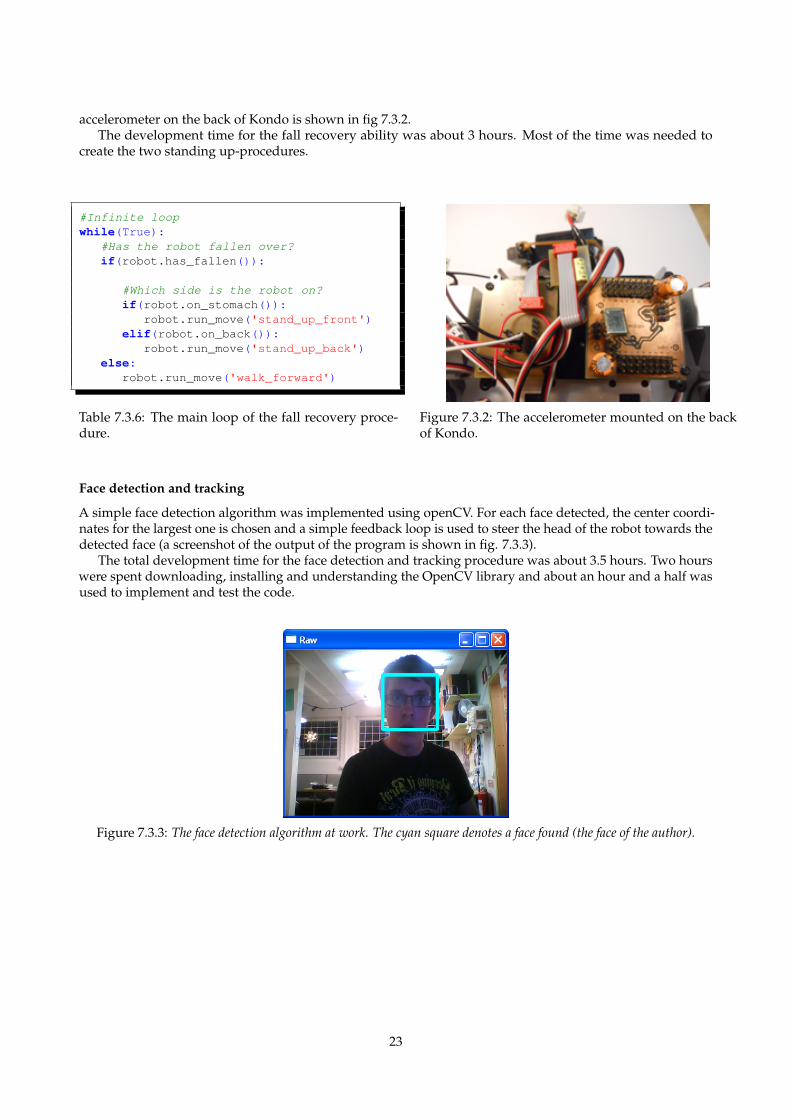
#Infinite loopwhile(True):
#Has the robot fallen over?if(robot.has_fallen()):
#Which side is the robot on?if(robot.on_stomach()):
robot.run_move('stand_up_front')elif(robot.on_back()):
robot.run_move('stand_up_back')else:
robot.run_move('walk_forward')
Table 7.3.6: The main loop of the fall recovery proce-dure.
Figure 7.3.2: The accelerometer mounted on the backof Kondo.
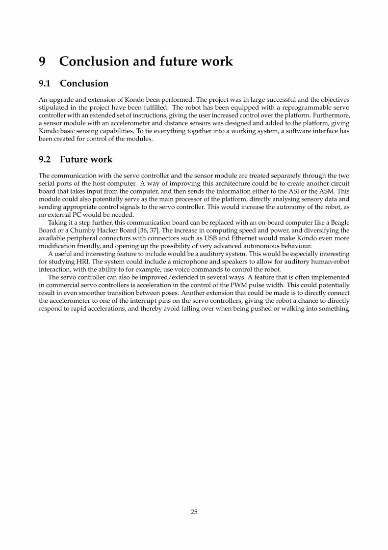
Face detection and tracking
A simple face detection algorithm was implemented using openCV. For each face detected, the center coordi-nates for the largest one is chosen and a simple feedback loop is used to steer the head of the robot towards thedetected face (a screenshot of the output of the program is shown in fig. 7.3.3).
The total development time for the face detection and tracking procedure was about 3.5 hours. Two hourswere spent downloading, installing and understanding the OpenCV library and about an hour and a half wasused to implement and test the code.
Figure 7.3.3: The face detection algorithm at work. The cyan square denotes a face found (the face of the author).
23
8 DiscussionThe platform has been upgraded with complementary systems, including a servo controller and a sensormodule has been created. The actual improvement in performance of the servo controller is relatively small.However, most significant improvement from changing from the RCB-1 boards to the ASC board is that itopens up the entire platform to extension and modification, as it is reprogrammable. Features can be added orremoved from the servo controller using a simple Atmel-compatible programmer.
The most important new feature of the upgraded platform is probably the addition of a sensory system.This has opened up a whole range of possibilities for Kondo, such as interacting with and adapting to anunstructured environment. The sensory system has also been important for the creation of the fall recoveryprocedure.
The testing of the standing up procedure indicates that it is robust and relatively fast (section 7.3.1). Themotion for walking forward and turning are quite slow and can be improved 7.3.1. However, they can serve asa basis for the development for faster, more robust gaits.
The objective of making the platform more easily accessible to both people with low robotic experience,and more experienced users, this has also been achieved. The programs created in the extendibility testing(section 7.3.2) are very crude sketches of how these features would be implemented in real robotic applications(in the wall avoidance program, the robot only turns to the left, for example). However, the created examplesshows that new features can easily be added to and integrated with the new system.
24
9 Conclusion and future work9.1 Conclusion
An upgrade and extension of Kondo been performed. The project was in large successful and the objectivesstipulated in the project have been fulfilled. The robot has been equipped with a reprogrammable servocontroller with an extended set of instructions, giving the user increased control over the platform. Furthermore,a sensor module with an accelerometer and distance sensors was designed and added to the platform, givingKondo basic sensing capabilities. To tie everything together into a working system, a software interface hasbeen created for control of the modules.
9.2 Future work
The communication with the servo controller and the sensor module are treated separately through the twoserial ports of the host computer. A way of improving this architecture could be to create another circuitboard that takes input from the computer, and then sends the information either to the ASI or the ASM. Thismodule could also potentially serve as the main processor of the platform, directly analysing sensory data andsending appropriate control signals to the servo controller. This would increase the autonomy of the robot, asno external PC would be needed.
Taking it a step further, this communication board can be replaced with an on-board computer like a BeagleBoard or a Chumby Hacker Board [36, 37]. The increase in computing speed and power, and diversifying theavailable peripheral connectors with connectors such as USB and Ethernet would make Kondo even moremodification friendly, and opening up the possibility of very advanced autonomous behaviour.
A useful and interesting feature to include would be a auditory system. This would be especially interestingfor studying HRI. The system could include a microphone and speakers to allow for auditory human-robotinteraction, with the ability to for example, use voice commands to control the robot.
The servo controller can also be improved/extended in several ways. A feature that is often implementedin commercial servo controllers is acceleration in the control of the PWM pulse width. This could potentiallyresult in even smoother transition between poses. Another extension that could be made is to directly connectthe accelerometer to one of the interrupt pins on the servo controllers, giving the robot a chance to directlyrespond to rapid accelerations, and thereby avoid falling over when being pushed or walking into something.
25
References[1] Erico Guizzoi. 6.5 Million Robots Now Inhabit the Earth. Oct. 2011. URL: http://spectrum.ieee.
org/automaton/robotics/robotics-software/world_robot_population_reaches_6_and_half_million.
[2] Robot Definitions. Oct. 2011. URL: http://en.wikipedia.org/wiki/Robot#Definitions.[3] George A Bekey. Autonomous robots: from biological inspiration to implementation and control. MIT Press,
June 2005. ISBN: 0-262-02578-7.[4] Robin Murphy. Introduction to AI robotics. MIT Press, 2000. ISBN: 0-262-13383-0.[5] Matthias Wahde. Approaches to machine intelligence. University Lecture. 2011. URL: http://www.me.ch
almers.se/˜mwahde/courses/aa/2011/FFR125_Chapter5.pdf.[6] Chess Computers. Sept. 2011. URL: http://en.wikipedia.org/wiki/Computer_chess.[7] Derek Wadsworth and Doug Few. Behavior-Based Robotics. Nov. 2011. URL: https://inlportal.inl.
gov/portal/server.pt?open=512&objID=526&mode=2.[8] Kolja Kuhnlenz Tingting Xu and Martin Buss. “Autonomous Behavior-Based Switched Top-Down and
Bottom-Up Visual Attention for Mobile Robots”. In: IEEE Transactions On Robotics 26 (2010), pp. 947–954.[9] Matthias Wahde. Autonomous Agents. University Lecture. 2011. URL: http://www.me.chalmers.se/
˜mwahde/courses/aa/2011/FFR125_Chapter5.pdf.[10] Matthias Toussaint. T.O.B.B, Two-wheeled robot. Sept. 2011. URL: http://www.mtoussaint.de/tob
b/index.html.[11] Masaaki Kumagai. Development of a Robot Balanced on a Ball - First Report, Implementation of the Robot and
Basic Control -. Sept. 2009. URL: http://www.mech.tohoku-gakuin.ac.jp/rde/index_e.html.[12] Ken Dye. Inverted Pendulum Balancing.[13] Miomir Vukobratovi and Branisalv Borovac. “Zero Moment Point. Thirty Five Years of its Life”. In:
International Journal of Humanoid Robotics 1 (2004), pp. 157–173.[14] Honda Motor Co. Ltd. Achieving Stable Walking. Sept. 2011. URL: http://world.honda.com/ASIM
O/history/technology2.html.[15] Speed of sound. Nov. 2011. URL: http://en.wikipedia.org/wiki/Speed_of_sound.[16] Piyush Khandelwal and Peter Stone. “A Low Cost Ground Truth Detection System Using the Kinect”.
In: Proceedings of the RoboCup International Symposium 2011 (RoboCup 2011). July 2011. URL: http://www.cs.utexas.edu/users/ai-lab/pub-view.php?PubID=127100.
[17] Hacked Microsoft Kinect Used for Controlling Robots. Nov. 2011. URL: http://news.softpedia.com/news/Hacked-Microsoft-Kinect-Used-for-Controlling-Robots-168490.shtml.
[18] Kowama.de. Achievable Accuracy. Oct. 2011. URL: http://www.kowoma.de/en/gps/accuracy.html.
[19] Matthias Wahde. Autonomous Agents. University Lecture. 2011. URL: http://www.me.chalmers.se/˜mwahde/courses/aa/2011/FFR125_Chapter1.pdf.
[20] History. May 2011. URL: robosavvy.com/KHR1Info/2.[21] KHR-1. Nov. 2011. URL: http://en.wikipedia.org/wiki/KHR-1.[22] Krister Wolff, David Sandberg, and Mattias Wahde. “Evolutionary optimization of a bipedal gait in a
physical robot”. In: 2008 IEEE World Congress on Computational Intelligence (2008). Ed. by JunEditor Wang,pp. 440–445. URL: http://ieeexplore.ieee.org/lpdocs/epic03/wrapper.htm?arnumber=4630835.
[23] Kit Content. May 2011. URL: robosavvy.com/KHR1Info/1.[24] Daniel Albert. RCB-1 Command Reference. July 2011. URL: http://unikluni.uni-klu.ac.at/
?p=46.[25] The RealTerm website. May 2011. URL: http://realterm.sourceforge.net/.[26] USBtinyISP website. Sept. 2011. URL: http://www.ladyada.net/make/usbtinyisp/.[27] PyDev website. May 2011. URL: http://pydev.org/.[28] pySerial API. Oct. 2011. URL: http://pyserial.sourceforge.net/.[29] wxPython website. May 2011. URL: http://www.wxpython.org/.[30] openCV website. Oct. 2011. URL: http://opencv.willowgarage.com/wiki/.[31] 8-bit Atmel Microcontroller with 4,8,16K Bytes In-System Programmable Flash. Atmel Corporation, 2011.[32] Freescale Semiconductor. MMA7455L Datasheet. Sept. 2011. URL: http://www.freescale.com/fil
es/sensors/doc/data_sheet/MMA7455L.pdf.
26
[33] GP2D120XJ manual. Optoelectronic Device. Sharp Corporation, 2006.[34] GP2Y0A21YK manual. Optoelectronic Device. Sharp Corporation, 2005.[35] PySerial. The PySerial website. Oct. 2011. URL: http://pyserial.sourceforge.net/.[36] BeagleBoard.org. Sept. 2011. URL: http://beagleboard.org.[37] chumbyhackerboard [AdaWiki]. Sept. 2011. URL: http://wiki.ladyada.net/chumbyhackerboard.[38] Society of Robots. Society of Robots: Description of UART. June 2011. URL: http://www.societyofrob
ots.com/microcontroller_uart.shtml.
27
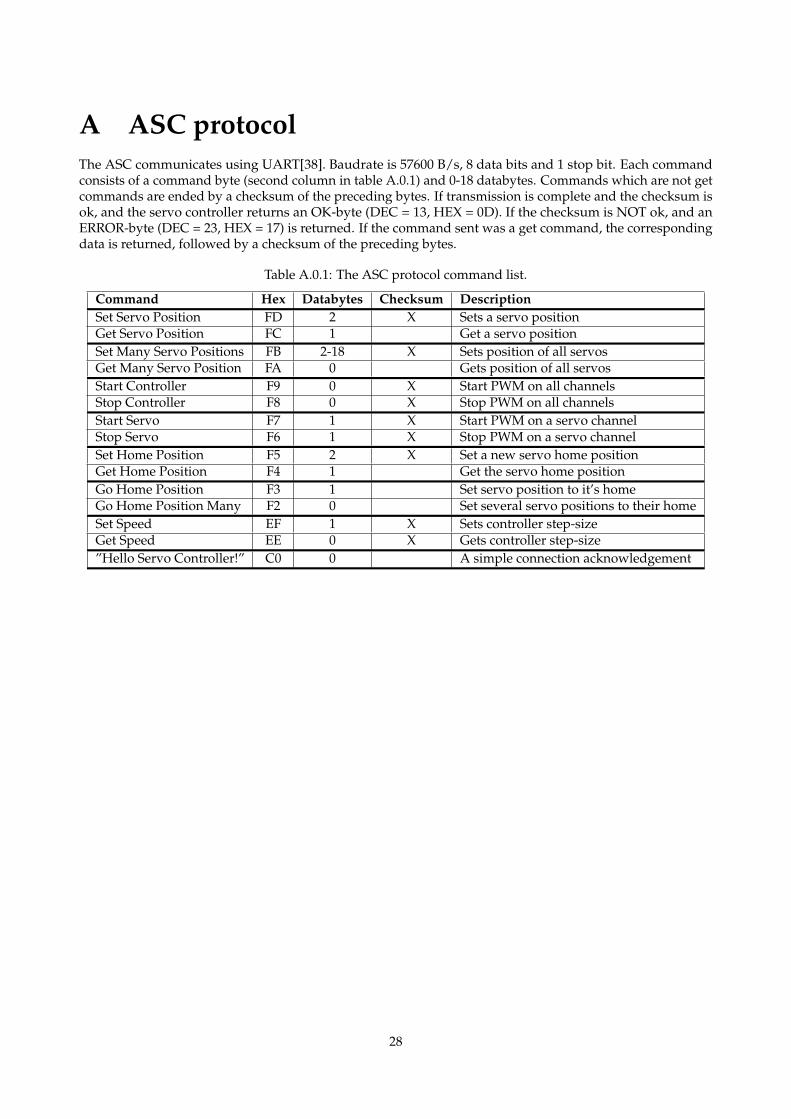
A ASC protocolThe ASC communicates using UART[38]. Baudrate is 57600 B/s, 8 data bits and 1 stop bit. Each commandconsists of a command byte (second column in table A.0.1) and 0-18 databytes. Commands which are not getcommands are ended by a checksum of the preceding bytes. If transmission is complete and the checksum isok, and the servo controller returns an OK-byte (DEC = 13, HEX = 0D). If the checksum is NOT ok, and anERROR-byte (DEC = 23, HEX = 17) is returned. If the command sent was a get command, the correspondingdata is returned, followed by a checksum of the preceding bytes.
Table A.0.1: The ASC protocol command list.
Command Hex Databytes Checksum DescriptionSet Servo Position FD 2 X Sets a servo positionGet Servo Position FC 1 Get a servo positionSet Many Servo Positions FB 2-18 X Sets position of all servosGet Many Servo Position FA 0 Gets position of all servosStart Controller F9 0 X Start PWM on all channelsStop Controller F8 0 X Stop PWM on all channelsStart Servo F7 1 X Start PWM on a servo channelStop Servo F6 1 X Stop PWM on a servo channelSet Home Position F5 2 X Set a new servo home positionGet Home Position F4 1 Get the servo home positionGo Home Position F3 1 Set servo position to it’s homeGo Home Position Many F2 0 Set several servo positions to their homeSet Speed EF 1 X Sets controller step-sizeGet Speed EE 0 X Gets controller step-size”Hello Servo Controller!” C0 0 A simple connection acknowledgement
28
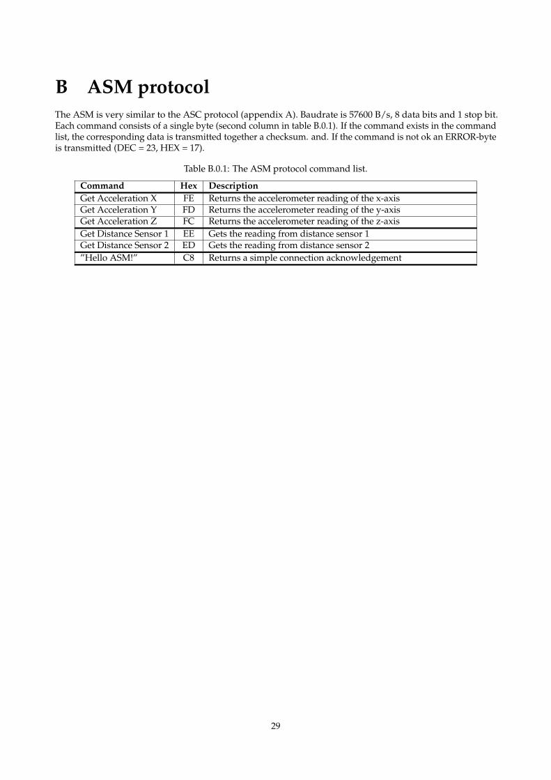
B ASM protocolThe ASM is very similar to the ASC protocol (appendix A). Baudrate is 57600 B/s, 8 data bits and 1 stop bit.Each command consists of a single byte (second column in table B.0.1). If the command exists in the commandlist, the corresponding data is transmitted together a checksum. and. If the command is not ok an ERROR-byteis transmitted (DEC = 23, HEX = 17).
Table B.0.1: The ASM protocol command list.
Command Hex DescriptionGet Acceleration X FE Returns the accelerometer reading of the x-axisGet Acceleration Y FD Returns the accelerometer reading of the y-axisGet Acceleration Z FC Returns the accelerometer reading of the z-axisGet Distance Sensor 1 EE Gets the reading from distance sensor 1Get Distance Sensor 2 ED Gets the reading from distance sensor 2”Hello ASM!” C8 Returns a simple connection acknowledgement
29