a (not so!?) brief introduction to the 32-bit mips processor architecture
TRANSCRIPT
A (not so!?) brief introduction to the 32-bit MIPS processor
architecture

The MIPS family tree

Pipeline architecture
• All MIPS processors use some variation of a pipeline in their architecture.
• A (MIPS) pipeline is divided into the following discrete parts, or stages (see ref. 1 (lacks details)):1. Fetch2. Arithmetic operation3. Memory access4. Write back

4-stages, but only single pipeline
• 1 issued every 4 clock cycles

4 pipelines
• 1 issued every clock cycle

Superpipeline(2 issued every clock cycle)

Superscalar pipeline
• Parallel start and completion. (Note: 5 stages below.)

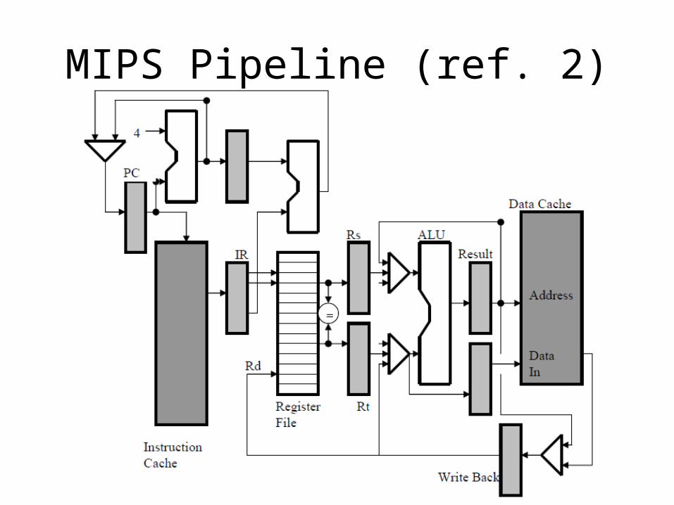
MIPS Pipeline (ref. 2)1. Fetch the instruction from cache memory and load it into the Instruction register (IR).
Increment the Program Counter (PC) by four.
2. Fetch values Rs and Rt from the Register File. If it is a branch instruction and the branch condition is met, then load the PC with the branch target address.
3. Perform an arithmetic or logic function in the ALU. This is the stage where an addition is performed to calculate the effective address for a load or store instruction.
4. If the instruction is a load, read from the data cache. If the instruction is a store, write to the data to cache. Otherwise, pass the data in the Result register on to the Write Back register.
5. Store the value in the Write Back register to the Register File. Notice that when the first instruction into the pipeline is storing results back to the Register File the fourth instruction into the pipeline is simultaneously reading from the register file.
MIPS Pipeline (ref. 2)
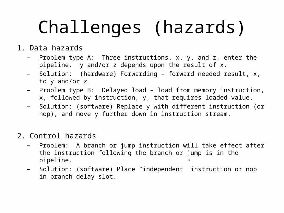
Challenges (hazards)1. Data hazards
– Problem type A: Three instructions, x, y, and z, enter the pipeline. y and/or z depends upon the result of x.
– Solution: (hardware) Forwarding – forward needed result, x, to y and/or z.– Problem type B: Delayed load – load from memory instruction, x, followed
by instruction, y, that requires loaded value.– Solution: (software) Replace y with different instruction (or nop), and move
y further down in instruction stream.
2. Control hazards– Problem: A branch or jump instruction will take effect after the instruction
following the branch or jump is in the pipeline.– Solution: (software) Place “independent” instruction or nop in branch delay
slot.

CPU (int) data formats
• The CPU defines the following data formats:
1. Bit (b)2. Byte (8 bits, B)3. Halfword (16 bits, H)4. Word (32 bits, W)5. Doubleword (64 bits, D)
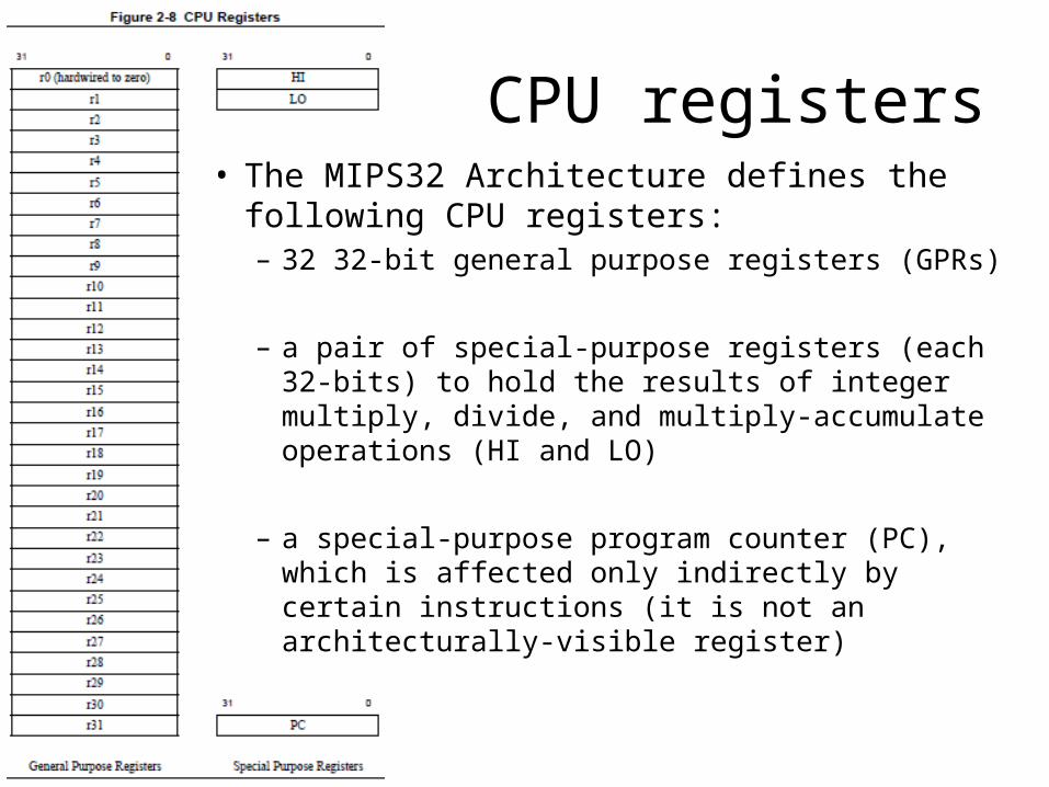
CPU registers• The MIPS32 Architecture defines the following
CPU registers:– 32 32-bit general purpose registers (GPRs)
– a pair of special-purpose registers (each 32-bits) to hold the results of integer multiply, divide, and multiply-accumulate operations (HI and LO)
– a special-purpose program counter (PC), which is affected only indirectly by certain instructions (it is not an architecturally-visible register)

CPU GPRs
• Two of the CPU general-purpose registers have assigned functions:1. r0 is hard-wired to a value of zero, and can be used as the
target register for any instruction whose result is to be discarded. r0 can also be used as a source when a zero value is needed.
2. r31 is the destination register used by JAL, BLTZAL, BLTZALL, BGEZAL, and BGEZALL without being explicitly specified in the instruction word. Otherwise r31 is used as a normal register.
• The remaining registers are available for general-purpose use.
CPU special purpose registers
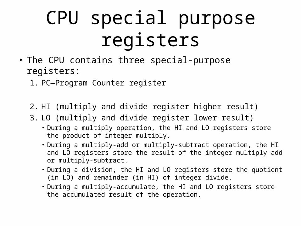
• The CPU contains three special-purpose registers:1. PC—Program Counter register
2. HI (multiply and divide register higher result)3. LO (multiply and divide register lower result)
• During a multiply operation, the HI and LO registers store the product of integer multiply.
• During a multiply-add or multiply-subtract operation, the HI and LO registers store the result of the integer multiply-add or multiply-subtract.
• During a division, the HI and LO registers store the quotient (in LO) and remainder (in HI) of integer divide.
• During a multiply-accumulate, the HI and LO registers store the accumulated result of the operation.

Suggested GPR uses:
• constant 0

Suggested GPR uses:
• May be used as temporary register during macro expansion via assembler. (So avoid using it.)Example:
Load Address (used to initialize pointers): la Rd, Label
lui $at, Upper-16-bits-of-Labelori Rd, $at, Lower-16-bits of-Label

Suggested GPR uses:
• function return values (2), and
• expression evaluation

Suggested GPR uses:
• function arguments (4)

Suggested GPR uses:
• temporary (not preserved)

Suggested GPR uses:
• temporary (preserved)

Suggested GPR uses:
• global pointer• stack pointer• frame pointer• return address

Overview of the CPU instruction set
• CPU instructions are organized into the following functional groups:1. Load and store2. Computational3. Jump and branch4. Miscellaneous5. Coprocessor
• Each instruction is 32 bits long.

CPU LOAD AND STORE INSTRUCTIONS
CPU load and store instructions
• MIPS processors use a load/store architecture; all operations are performed on operands held in processor registers and main memory is accessed only through load and store instructions.

Types of loads and stores
• There are several different types of load and store instructions, each designed for a different purpose:– transferring variously-sized fields (for example, LB, SW)– trading transferred data as signed or unsigned integers
(for example, LHU)– accessing unaligned fields (for example, LWR, SWL)– selecting the addressing mode (for example, SDXC1, in the
FPU)– atomic memory update (read-modify-write: for instance,
LL/SC)
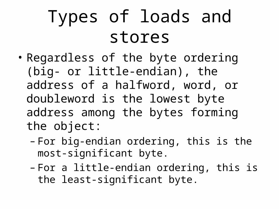
Types of loads and stores
• Regardless of the byte ordering (big- or little-endian), the address of a halfword, word, or doubleword is the lowest byte address among the bytes forming the object:– For big-endian ordering, this is the most-
significant byte.– For a little-endian ordering, this is the least-
significant byte.


COMPUTATIONAL INSTRUCTIONS
Computational instructions
• ALU Immediate
• ALU Three-Operand
• ALU Two-Operand
• Shift
• Multiply and Divide

ALU Immediate (16-bit) Instructions

ALU Three-Operand Instructions

ALU Three-Operand Instructions (cont’d.)

ALU Two-Operand Instructions

Shift Instructions

Shift Instructions (cont’d.)

Multiply and Divide Instructions• The multiply and divide instructions produce twice as many result bits.• With one exception (MUL), they deliver their results into the HI and LO
special registers. (The MUL instruction delivers the lower half of the result directly to a GPR.)– Multiply produces a full-width product twice the width of the input operands;
the low half is loaded into LO and the high half is loaded into HI.– Multiply-Add and Multiply-Subtract produce a full-width product twice the
width of the input operations and adds or subtracts the product from the concatenated value of HI and LO. The low half of the addition is loaded into LO and the high half is loaded into HI.
– Divide produces a quotient that is loaded into LO and a remainder that is loaded into HI.
• The results are accessed by instructions that transfer data between HI/LO and the general registers.
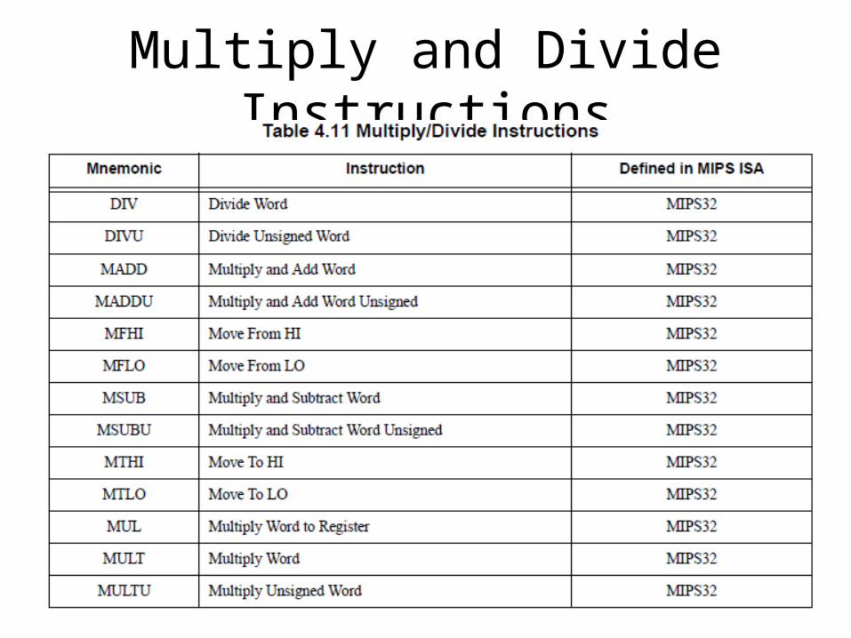
Multiply and Divide Instructions

JUMP AND BRANCH INSTRUCTIONS

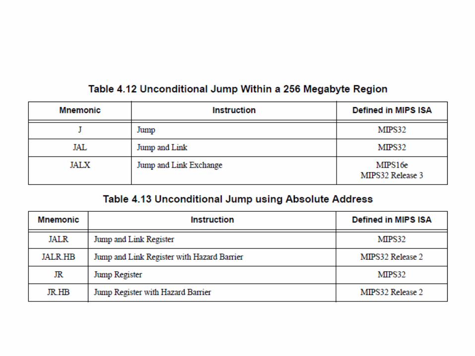
Types of jump and branch instructions
• The architecture defines the following jump and branch instructions:1. PC-relative conditional branch2. PC-region unconditional jump3. Absolute (register) unconditional jump4. A set of procedure calls that record a return link
address in a general register.


Branch delays and the branch delay slot• All branches have an architectural delay of
one instruction.
• The instruction immediately following a branch is said to be in the branch delay slot. (If a branch or jump instruction is placed in the branch delay slot, the operation of both instructions is UNPREDICTABLE!)

Branch delays and the branch delay slot• There are two versions of branches and jumps; they
differ in the manner in which they handle the instruction in the delay slot when the branch is not taken and execution falls through.1. Branch and Jump instructions execute the instruction in
the delay slot.2. Branch Likely instructions do not execute the instruction
in the delay slot if the branch is not taken.1. Software is strongly encouraged to avoid the use of the Branch
Likely instructions, as they will be removed from a future revision of the MIPS Architecture.

MISCELLANEOUS INSTRUCTIONS

Miscellaneous instructions
• Miscellaneous instructions include:1. instruction serialization (SYNC and SYNCI)2. exception instructions3. conditional move instructions4. prefetch instructions5. NOP instructions

1. Instruction serialization

2. Exceptioninstructions

3. Conditional move instructions

4. Prefetch instructions

5. NOP instructions

COPROCESSOR INSTRUCTIONS
Coprocessors
• The MIPS Architecture defines four coprocessors (designated CP0, CP1, CP2, and CP3):– Coprocessor 0 (CP0) is incorporated on the CPU chip and
supports the virtual memory system and exception handling. CP0 is also referred to as the System Control Coprocessor.• CP0 translates virtual addresses into physical addresses, manages
exceptions, and handles switches between kernel, supervisor, and user states. CP0 also controls the cache subsystem, as well as providing diagnostic control and error recovery facilities.

Coprocessors (cont’d.)
• The MIPS Architecture defines four coprocessors (designated CP0, CP1, CP2, and CP3):– Coprocessor 1 (CP1) is reserved for the floating point
coprocessor, the FPU.– Coprocessor 2 (CP2) is available for specific
implementations.– Coprocessor 3 (CP3) is reserved for the floating point unit
in a Release 1 implementation of the MIPS64 Architecture, and on all Release 2 (and subsequent releases) implementations of the Architecture.

Coprocessor instructions

Note
• We have not discussed MIPS floating point instructions.

FPU data formats
• The FPU defines the following data formats:– Floating point (in IEEE 754 format):
1. 32-bit single-precision floating point (.fmt type S)2. 32-bit single-precision floating point paired-single
(.fmt type PS)3. 64-bit double-precision floating point (.fmt type D)
– Fixed point:1. 32-bit Word fixed point (.fmt type W)2. 64-bit Long fixed point (.fmt type L)


FPU registers
• The MIPS32 Architecture defines the following FPU registers:– 32 floating point registers (FPRs). These registers
are 32 bits wide in a 32-bit FPU (and 64 bits wide on a 64-bit FPU).
– Five FPU control registers are used to identify and control the FPU.
– Eight floating point condition codes that are part of the FCSR register.
FPU registers
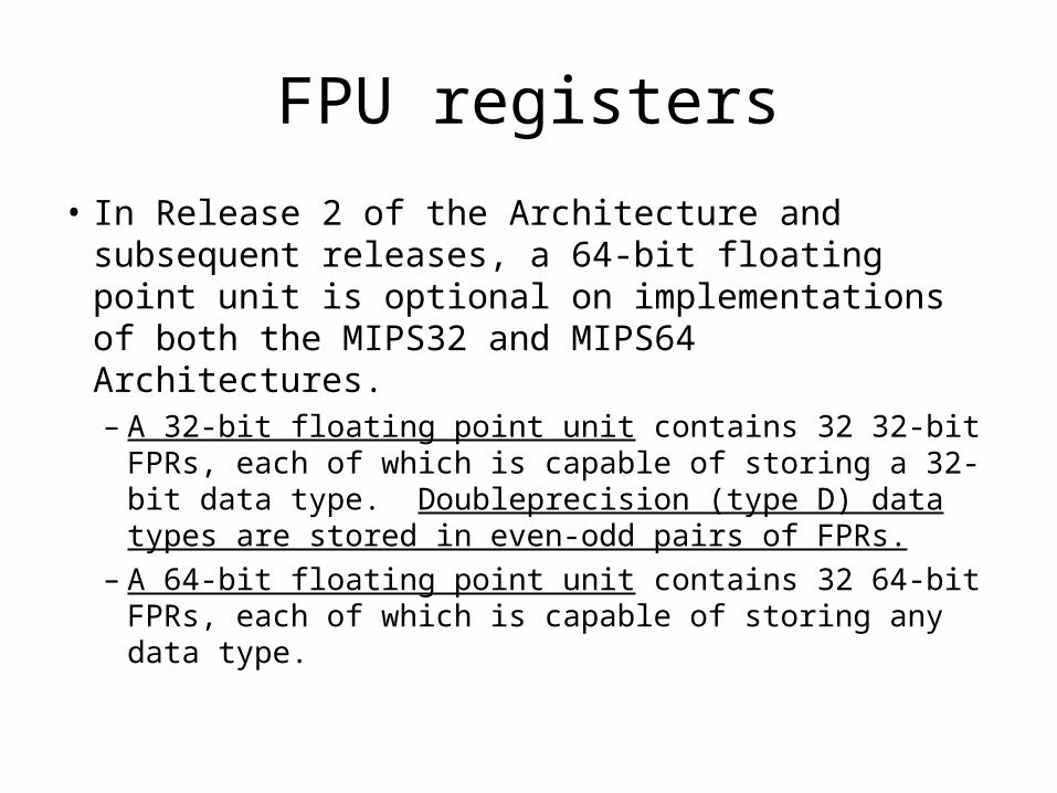
• In Release 2 of the Architecture and subsequent releases, a 64-bit floating point unit is optional on implementations of both the MIPS32 and MIPS64 Architectures.– A 32-bit floating point unit contains 32 32-bit FPRs,
each of which is capable of storing a 32-bit data type. Doubleprecision (type D) data types are stored in even-odd pairs of FPRs.
– A 64-bit floating point unit contains 32 64-bit FPRs, each of which is capable of storing any data type.

FPU registers (MIPS32 & MIPS64):
FPU instructions:
1. Data transfer2. Arithmetic3. Conversion4. Formatted operand-value move5. Conditional branch6. Miscellaneous

FPU instructions: data transfer

FPU instructions: data transfer (cont’d.)

FPU instructions: arithmetic

FPU instructions: arithmetic (cont’d.)

FPU instructions: arithmetic (cont’d.)

FPU instructions: conversion
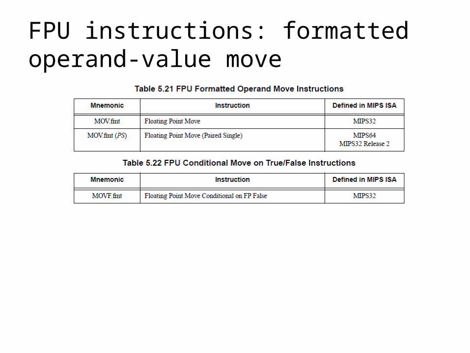
FPU instructions: formatted operand-value move

FPU instructions: formatted operand-value move (cont’d.)

FPU instructions: conditional branch

FPU instructions: miscellaneous
Operating modes
1. User2. Kernel3. Supervisor (optional)4. EJTAG Debug (optional)

SPIM – THE MIPS SIMULATOR (SPIMULATOR?)
http://spimsimulator.sourceforge.net/

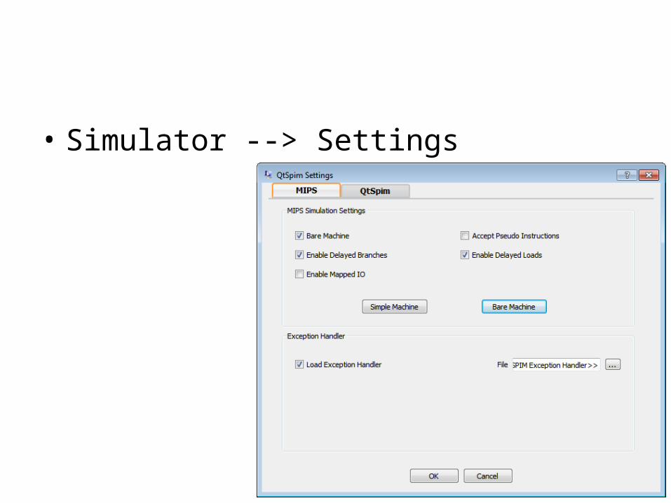
• Simulator --> Settings
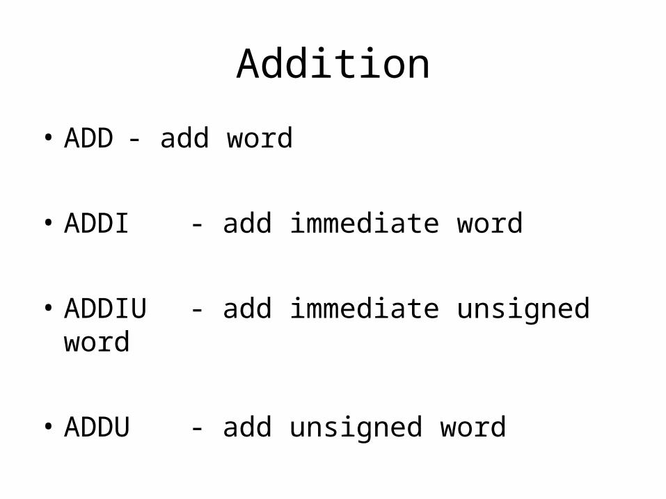
Addition
• ADD - add word
• ADDI - add immediate word
• ADDIU - add immediate unsigned word
• ADDU - add unsigned word

ADD (signed, 32-bit registers)

ADDI (signed, 32-bit register + 16-bit immediate)

ADDIU (unsigned 32-bit register + signed 16-bit immediate)
• (Note: Simply allows one to increase or decrease an unsigned value.)

ADDU (unsigned, 32-bit registers)

Subtraction
• SUB - subtract word
• SUBU - subtract unsigned word

SUB (signed, 32-bit)

SUBU (unsigned, 32-bit)

Function calls and returns
• BAL - branch and link• +/- 128K offset
• JAL - jump and link• within the current 256MB-aligned region
• JALR - jump and link register• destination function specified by 32-bits in register
• Return instruction? None! Use JR $ra (Jump Register) instead.

SPIM subset of MIPS assembler directives: code
.align nAlign the next datum on a 2 n byte boundary. For example, .align 2 aligns the next value on a word boundary. .align 0 turns off automatic alignment of .half, .word, .float, and .double directives until the next .data or .kdata directive.
.extern sym sizeDeclare that the datum stored at sym is size bytes and is a global label. This directive enables assembler to store the datum in a portion of data segment that is efficiently accessed via register $gp.
.globl symDeclare that label sym is global and can be referenced from other files.
.ktextSubsequent items are put in the kernel text segment. In SPIM, these items may only be instructions or words (see the .word directive below). If the optional argument addr is present, subsequent items are stored starting at address addr.
.set noat and .set atThe first directive prevents SPIM from complaining about subsequent instructions that use register $at. The second directive reenables the warning. Since pseudoinstructions expand into code that uses register $at, programmers must be very careful about leaving values in this register.
.text <addr>Subsequent items are put in the user text segment. In SPIM, these items may only be instructions or words (see the .word directive below). If the optional argument addr is present, subsequent items are stored starting at address addr.

SPIM subset of MIPS assembler directives: data
.align nAlign the next datum on a 2n byte boundary. For example, .align 2 aligns the next value on a word boundary. .align 0 turns off automatic alignment of .half, .word, .float, and .double directives until the next .data or .kdata directive.
.dataSubsequent items are stored in the data segment. If the optional argument addr is present, subsequent items are stored starting at address addr. (SPIM does not distinguish various parts of the data segment (.data, .rdata, and .sdata).)
.kdataSubsequent data items are stored in the kernel segment. If the optional argument addr is present, subsequent items are stored starting at address addr.

SPIM subset of MIPS assembler directives: data allocation
.ascii strStore the string str in memory, but do not null-terminate it.
.asciiz strStore the string str in memory and null-terminated it.
.byte b1, ..., bnStore the n values in successive bytes of memory.
.double d1, ..., dnStore the n floating-point double precision numbers in successive memory locations.
.extern sym sizeDeclare that the datum stored at sym is size bytes and is a global label. This directive enables assembler to store the datum in a portion of data segment that is efficiently accessed via register $gp.
.float f1, ..., fnStore the n floating-point single precision numbers in successive memory locations.
.half h1, ..., hnStore the n 16-bit quantities in successive memory halfwords.
.space nAllocate n bytes of space in the current segment (which must be the data segment in SPIM).
.word w1, ..., wnStore the n 32-bit quantities in successive memory words.

References
1. MIPS® Architecture For Programmers Volume I-A: Introduction to the MIPS32® Architecture, Revision 3.02, 2011, Document Number: MD00082, MIPS Technologies Inc.
2. MIPS Assemby Language Programming, Robert L. Britton, 2002.
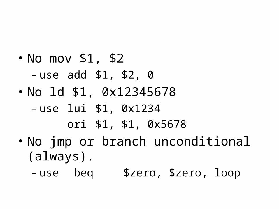
• No mov $1, $2– use add $1, $2, 0
• No ld $1, 0x12345678– use lui $1, 0x1234
ori $1, $1, 0x5678
• No jmp or branch unconditional (always).– use beq $zero, $zero, loop