a novel wireless power transmission system using ...ap-s.ei.tuat.ac.jp/isapx/2016/pdf/pos1-123.pdfa...
TRANSCRIPT
A Novel Wireless Power Transmission System Using Microstrip Coil Structure with Ferrite and
Dielectric Layers
Fang-Hua Liu, Shi Pu Department of Physics, School of Science, Wuhan University of Technology, 122 Luoshi Road, Wuhan, 430070, China
Abstract –In this paper, a novel wireless power transmission (WPT) system composed of microstrip coils with ferrite and dielectric layers is proposed. The structure of each microstrip coil includes a loop one placed outside and a spiral one put inside. It would be concluded that the transfer efficiency of the proposed WPT system with load of 50 Ohm can get up to around 59.7% at the resonant frequency of 13.56 MHz.
Index Terms — Wireless power transmission, Microstrip coil, Magnetic resonant coupling, Ferrite.
1. Introduction
In recent years, a great deal of research has been focused on the WPT issue because of its convenience in power charging device. Generally, the wireless power transfer methods can be divided into three categories: inductive transfer, radiative transfer and resonant transfer ways, which has been analyzed and summarized in Ref. [1]. Among these three methods, the resonant transfer way can deliver power with higher efficiency than the radiative transfer way and over larger range than the inductive transfer way, which was mentioned in Ref. [2]. Therefore, the resonant transfer way is chosen in this paper for the design of WPT system. In Section 2, a WPT system by replacing the wire coils designed in Ref. [3] with the microstrip coils, would be presented. Besides, two two-layer substrates made up of FR4 and ferrite were set respectively under transmitting coil (Tx) and above receiving coil (Rx) so as to improve the transfer efficiency, the effect of which has been demonstrated in Ref. [4] and Ref. [5]. Finally, our designed WPT system would be shown to be well resonant at the center frequency of 13.56 MHz with the transfer efficiency of around 59.7%.
2. Structure Design and Simulation Results
Fig. 1. Overall view of WPT system.
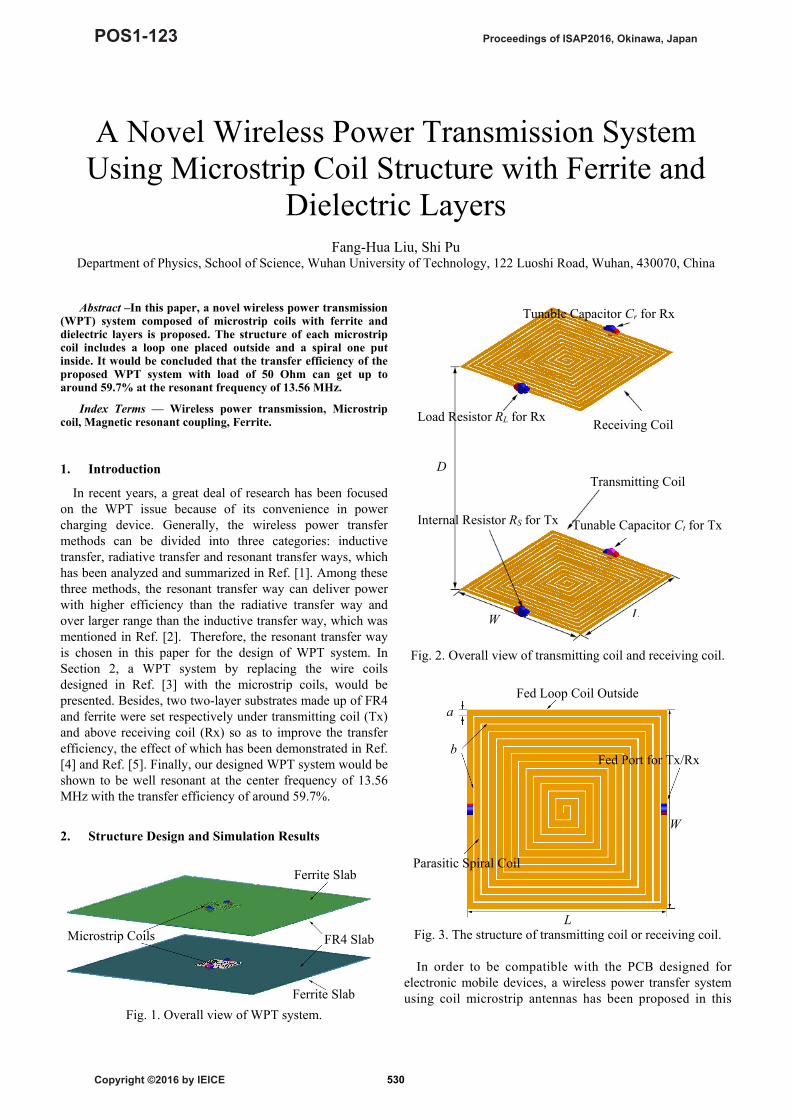
Fig. 2. Overall view of transmitting coil and receiving coil.
Fig. 3. The structure of transmitting coil or receiving coil.
In order to be compatible with the PCB designed for
electronic mobile devices, a wireless power transfer system using coil microstrip antennas has been proposed in this
Ferrite Slab
Microstrip Coils FR4 Slab
Ferrite Slab
D
W
Tunable Capacitor Cr for Rx
L
Load Resistor RL for Rx
Transmitting Coil
Receiving Coil
Internal Resistor RS for Tx Tunable Capacitor Ct for Tx
a
b
Fed Loop Coil Outside
L
W
Fed Port for Tx/Rx
Parasitic Spiral Coil
Proceedings of ISAP2016, Okinawa, Japan
Copyright ©2016 by IEICE
POS1-123
530

12.0 12.5 13.0 13.5 14.0 14.5 15.0-2000
-1000
0
1000
2000
3000 Real Part for Tx Port Imaginary Part for Tx Port
Inpu
t Im
peda
nce
(Ω)
Frequency (MHz)
Fig. 4. Input impedance of WPT system calculated from fed
port of Tx.
Output Power in Load Resistor Power Dissipated in Source Resistor Total input Power from Source supply
12.0 12.5 13.0 13.5 14.0 14.5 15.00
1
2
3
4
5
6
Pow
ers
(mW
)
Frequency (MHz) 13.56 MHz
Fig. 5. Three power parameters of WPT system.
12.0 12.5 13.0 13.5 14.0 14.5 15.00
20
40
60
80
Tra
nsfe
r E
ffic
ienc
y (%
)
Frequency (MHz)
Fig. 6. Transfer efficiency of WPT system.
paper. The system was designed and optimized by using FEKOTM, which is a commercial software based on method of moments (MoM). The whole structure of the proposed WPT system is drawn as in Fig. 1. The microstrip coil antenna is cladding on FR4 with the thickness of 2.0 mm. Moreover, the ferrite layer of 3.0 mm thickness set together with the FR4 layer, intends to uniform and reflect the magnetic-field energy for further transferring. The ferrite’s relative permeability and the magnetic loss tangent were set to be 1000 and zero. The overall view of the transmitting coil
and receiving coil is depicted as in Fig. 2. They are faced with each other and the distance between them is D = 30.0 cm. As drawn in Fig. 3, the transmitting/receiving antennas are made up of the port fed loop coil and the parasitic spiral coil, both of which are the microstrip design. The width of all microstrip lines is a = 5.685 mm and the in-between gap is b = 1.0 mm. Through optimization, the length of the transmitting/receiving antenna structure is L = 179.5 mm and its width is W = 178.5 mm, which is made of copper. The input source is with voltage magnitude of |VS| = 1.0 V and an internal resistor of RS = 50 Ω, while the output terminal is a load resistor of RL = 50 Ω. In addition, two equal tunable capacitors of Ct/Cr = 30.65 pF are set to connect with the transmitting/receiving coils so that the whole system can be well resonant at the frequency of 13.56 MHz.
To sweep the frequency band from 12.0 MHz to 15.0 MHz, the input impedance of the WPT system has been shown as in Fig. 4. It can be found that the impedance value matches well with (50.0 + j 0.0) Ω at the point of 13.56 MHz. Here, the transfer efficiency defined as [3] follows
ηeff = [Pl/(Pi-Ps)]×100% , (1)
where Pl, Pi and Ps are the power output from load resistor, total input from source supply, and dissipated in source resistor, as shown in Fig. 5 respectively. Therefore, the transfer efficiency reaches 59.7% at the frequency of 13.56 MHz as depicted in Fig. 6.
3. Conclusion
A wireless power transfer system using microstrip coil based on the magnetic resonant coupling has been designed and optimized by using a full-wave numerical method. This microstrip coil system can reach its maximum power transfer efficiency of nearly 60% and the impedance matches well with 50 Ω at the resonant frequency of 13.56 MHz.
Acknowledgment
The authors thank the assistance in simulation with FEKO from their engineers during the research process.
References
[1] J. I. Agbinya, Wireless Power Transfer, Aalborg: River Publishers, 2012.
[2] A. P. Sample, D. A. Meyer and J. R. Smith, “Analysis, experimental result s, and range adaptation of magnetically coupled resonators for wireless power transfer,” IEEE Trans. Ind. Electron., Vol. 58, No. 2, pp. 544-554, Feb. 2011.
[3] S. Pu, H. T.Hui, “An efficient wireless power transmission system by employing 3 × 3 stacked coil antenna arrays,” in RFID Technology and Applications (RFID-TA), Tokyo, Japan, Sept. 2015, pp 171-175.
[4] H. Kim, J. Cho, S. Ahn, J. Kim and J. Kim, “Suppression of leakage magnetic field from a wireless power transfer system using ferrimagnetic material and metallic shielding,” in Electromagnetic Compatibility (EMC), Pittsburgh, USA, Aug. 2012, pp 640-645.
[5] Seongheon Jeong, “Ferrite-loaded coil for uniform magnetic field distribution,” in Wireless Power Transfer Conference (WPTC), Boulder, USA, May. 2015, pp 1-3.
13.2 13.4 13.6 13.8-100
-50
0
50
100
Inpu
t im
peda
nce
(Ω)
Frequency (MHz)
13.56 MHz
531