a numerical study of forced convection...
TRANSCRIPT
1ST
INTERNATIONAL CONFERENCE in MECHANICAL ENGINEERING RESEARCH ( ICMER ) 2011
216
A Numerical Study of Forced Convection Heat Transfer
for Staggered Tube Banks in Cross-Flow
T. A. Tahseen
1, M. Ishak
1,2 and M. M. Rahman
1,2
1Faculty of Mechanical Engineering, University Malaysia Pahang
26600 Pekan, Pahang, Malaysia
Phone : +609-424-2246 ; Fax : +609-424-2202
Email: [email protected]; [email protected];
[email protected] 2Automotive Engineering Centre, Universiti Malaysia Pahang,
26600 Pekan, Pahang, Malaysia.
Abstract: This paper presents the numerical study on the two-dimensional forced
convection heat transfer for staggered tube banks in cross flow under
incompressible, steady-state conditions. This system is solved on the body fitted
coordinates (BFC) using the finite difference method (FDM) for the flow over a
bundle of cylindrical tubes. The constant heat flux is imposed on the surface of the
tubes as the thermal boundary condition. The type of the arrangement is considered
a staggered of tubes. The longitudinal pitch to tube diameter ratios (ST/D) of 1.25,
1.5 and 2 are also considered. Reynolds numbers are varied from 25 to 250 and
Prandtl number is taken as 0.71. Velocity field vectors and temperature contours,
local and average Nusselt numbers were analysed in this paper. It can be seen that
the predicted results are good agreements with previous experimental and
numerical results. The obtained results show that the heat transfer rate increases
with decreases of the step to the longitudinal tube diameter. The local heat transfer
strongly depends on the Reynolds number. It tends to obtain the highest values at
the surface opposite to the direction of flow. The heat transfer rate is insignificant
in the areas of recycling.
Keywords: Forced convection, cylindrical tube, staggered arrangement, body fitted
coordinates, finite different method.
1. Introduction
The flow of fluids and heat transfer in tube banks represents an idealization of many industrially
important processes. Tube bundles are widely employed in cross-flow heat exchangers, the
design is still based on empirical correlations of heat transfer and pressure drop. Heat
exchangers with tube banks in cross-flow are of great practical interest in many thermal and
chemical engineering processes (Incropera and Dewitt, 1996; Buyruk, 2002; Mandhani et al.
2002; Liang and Papadakis, 2007; Kaptan et al., 2008). A two dimensions numerical study
pressure drop, heat transfer and incompressible laminar flow for staggered tube arrays in cross-
flow (Yuan et al., 1998; Rahmani et al., 2005; Khan et al., 2006; Marchi and Hobmeir, 2007).
The low Reynolds number and Prandtl number equal to 0.71 are considered in general (Chang
et al., 1989; Wang and Georgiadis, 1996). An experimental study was carried out to investigate
heat transfer and flow characteristics from one tube within a staggered tube bundle and within a
row of similar tubes. Variation of a local Nusselt number and local pressure coefficients were
shown with different blockages and Reynolds numbers (Buyruk et al., 1998; Buyruk, 1999;
Matos et al., 2001, 2004). The experimental and numerical study pressure drop and heat transfer

1ST
INTERNATIONAL CONFERENCE in MECHANICAL ENGINEERING RESEARCH ( ICMER ) 2011
217
through bundles of parallel cylinders The numerical results cover the range 1≤ ReD ≤ 30,
0.72≤ Pr ≤ 100, 0.6 ≤ Φ ≤ 0.95 and 0o
≤ β ≤ 60°, where Φ is the porosity of the bundle as a
saturated porous medium, and β is the angle between the cylinder centreline. The experimental
measurements in the range of 1≤ ReD ≤ 30, 0.84 ≤ Φ ≤ 0.92 and 0° ≤ β ≤ 60°. The results show
that the significant errors may occur if the available large-ReD information is extrapolated to the
domain covered by this study (Fowler and Bejan, 1994). This is an experimental, numerical
and analytical study of the optimal spacing between cylinders in cross-flow forced
convection. The experimental ReD range of 50- 4000 and the second part, similar results are
developed based on numerical simulations for Pr = 0.72 and 40 ≤ ReD ≤ 200. The experimental
and numerical results for optimal spacing and maximum thermal conductance are explained and
correlated analytically by intersecting the small-spacing and large- spacing asymptotes of the
thermal conductance function (Stanescu et al., 1996). A calculation procedure for two-
dimensional elliptic flow is applied to predict the pressure drop and heat transfer characteristics
of laminar and turbulent flow of air across tube banks. The theoretical results of the present
model are compared with previously published experimental data (Wilson and Bassiouny,
2000). Cross-flow over tube banks are commonly encountered in practice in heat transfer
equipments. The average Nusselt number increases more than 30% and 65% on the second and
third tubes, respectively, in comparison with that of the first tube (Yoo et al., 2007). The
objective of this study is to numerical study of the two-dimension laminar incompressible flow
and heat transfer over a staggered circular tube bank. The local and average heat transfer
characteristics for staggered tube banks are investigated in the present study.
2. Methodology
The treated problem is a two-dimensional of a staggered tube bank with the diameter of tube
15mm and the SL=15mm. The equations governing the conservation of continuity, momentum,
and energy equation. Assuming constant thermophysical properties of the fluid, with two-
dimensional expressions in Cartesian vector notation for steady-state incompressible flow. The
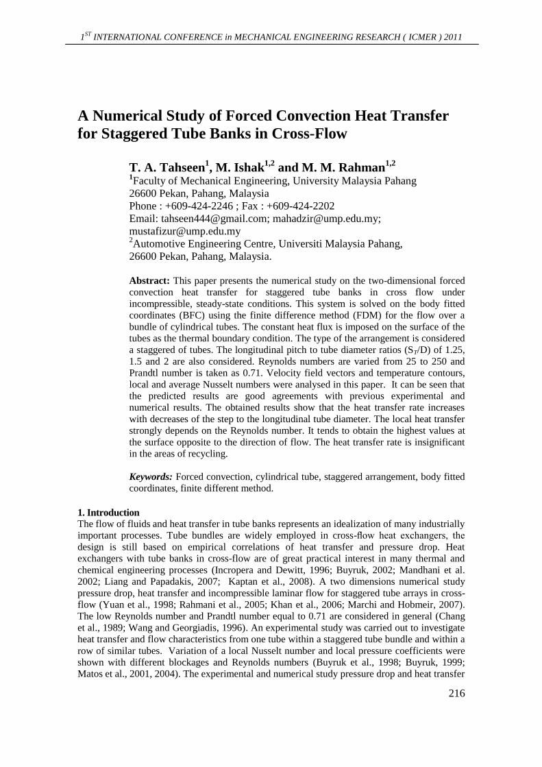
physical system considered in the present study is displayed in ‘figure 1’, are (Bejan, 1995):
Continuity: U V
0 (1)X Y
Momentum (Navier-Stokes): 2 2
2 2
D
2 2
2 2
D
V V P 1 U UX-direction (u momentum) U V
X Y X Re X Y(2)
V V P 1 V VY-direction (v momentum) U V
X Y X Re X Y
Energy: 2 2
2 2D
1U V (3)
X Y Pr Re X Y
The dimensionless variables have been defined based on appropriate physical scales as Eq. (4):
P
D2w
x, y u,v T T U D CpX,Y ,P ,(U,V) , ,Re ,Pr (4)
D U T T kU
The schematic of staggered tube banks and computational domain is shown in figure 1.
Boundary conditions are as follows:
V(I) U 1, 0, 0
X
U(B) 0, V 0, 0
Y Y
(A) U V 0, 1
U V(E) 0, 0
X X X
1ST
INTERNATIONAL CONFERENCE in MECHANICAL ENGINEERING RESEARCH ( ICMER ) 2011
218
Figure 1. Schematic of staggered tube banks and computational domain
The heat transfer coefficient (h) can be expressed in the dimensionless form by the local and
average Nusselt numbers Nu and Nu , which is defined as Eq. (5) and Eq. (6) respectively
(Chen and Wung, 1989):
hDNu (5)
k n
hDNu Nuds ds (6)
k
The set of conservation (Eq. 2 and Eq. 4) can be written in general form in Cartesian
coordinates as Eq. (7):
(U ) (V )S (7)
X Y X X Y Y
The continuity equation, Eq. (1) has no diffusion and source terms. It will be used to derive an
equation for the pressure correction. The grid generation scheme based on elliptic partial
differential equations is used in the present study to generate the curvilinear coordinates. Eq. (7)
can be transformed from the physical domain to the computational domain according to the
following transformation (x,y), (x,y) (Thompson et al. 1985). The final form of the
transformed equation can be written as Eq. (8):
1 2G G JS (8)J J
Where:
1 2
2 2 2 2
Y X X Y X Y Y XG U V , G V U , J
(9)x y x x y y x y
, ,

1ST
INTERNATIONAL CONFERENCE in MECHANICAL ENGINEERING RESEARCH ( ICMER ) 2011
219
Eq., (8) was solved numerically using a control volume-based finite difference method.
The solved by the marching type procedure envolving a series of two dimensional
elliptic problem in the cross-stream plane. The marching step size is 1 × 10⁻⁴
along the axial
distance. At each marching step, the strong coupling of pressure and velocity in the cross
section was calculated by the SIMPLER-algorithm on a collocated non-orthogonal grid. It is
used to adjust the velocity field to satisfy the conservation of mass (Patankar, 1980). For the
computational calculations, a computer code was prepared in FORTRAN-90. In the numerical
calculation, a146 × 21 grid arrangements are found to be sufficient for grid independent solution
and then the 2D-algbraic grid is generated.
Figure 2. Schematic of grid systems generated by body-fitted coordinates.
3. Validation
The numerical model was validated with some of previous published benchmark problems. The
fluid flow and heat transfer over a row of in a staggered circular tube subjected to constant wall
temperature and constant heat flux were predicted. The Nusselt number for the fully developed
region between two tubes subjected to constant wall temperature using by previous literatures.
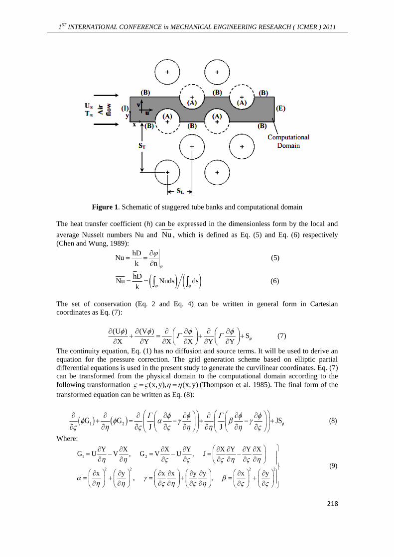
‘Figure 3’ shows comparison between the present study with previous literatures (( Kaptan et
al., 2008; Buyruk, 2002) for local Nusselt number with Re = 120, Pr = 0.71 and ST/D = 2.0. It
can be seen that an excellent agreement is achieved between the present results and the
numerical results of Kaptan et al. (2008) and Buyruk (2002), for the local Nusselt number
distribution circumference of the first tube.
1ST
INTERNATIONAL CONFERENCE in MECHANICAL ENGINEERING RESEARCH ( ICMER ) 2011
220
Figure 3. Comparison between the present study with previous literatures (Kaptan et al., 2008;
Buyruk, 2002) for local Nusselt number with Re =120, Pr = 0.71 and ST/D = 2.0
4. Results and Discussion
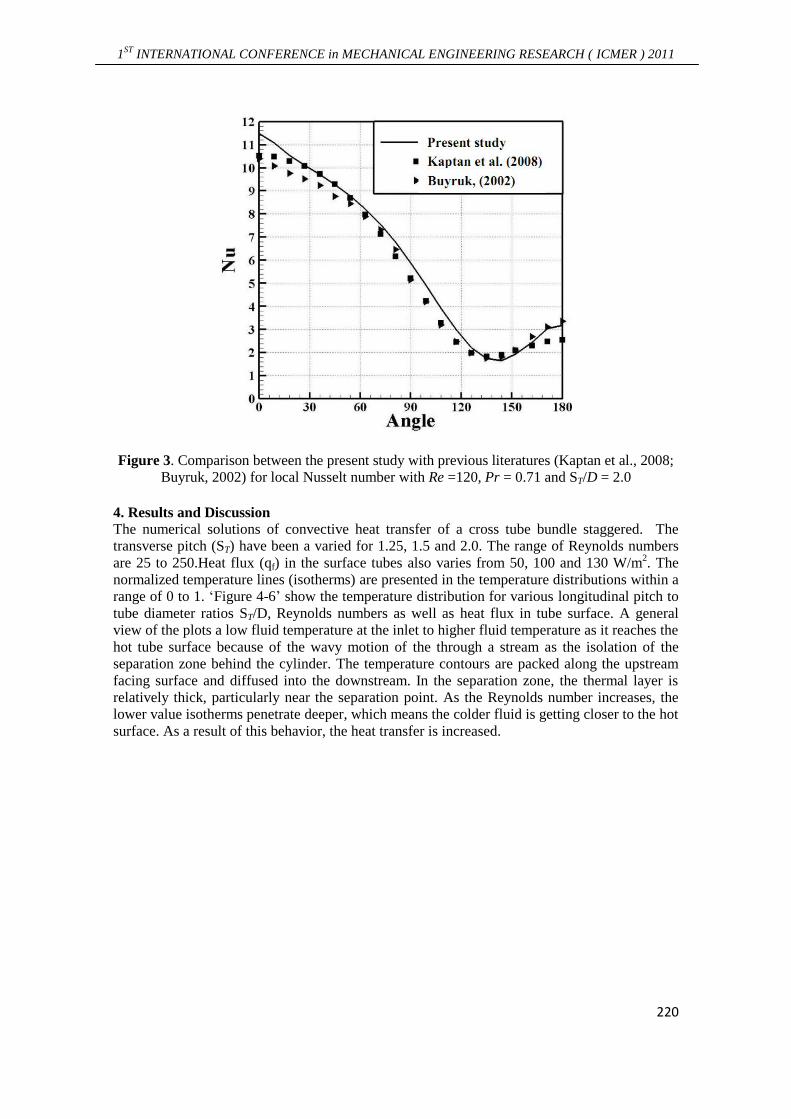
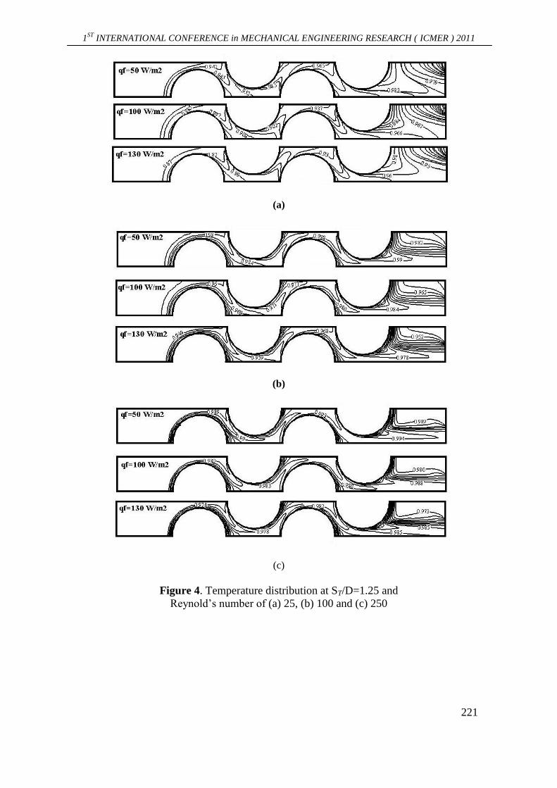
The numerical solutions of convective heat transfer of a cross tube bundle staggered. The
transverse pitch (ST) have been a varied for 1.25, 1.5 and 2.0. The range of Reynolds numbers
are 25 to 250.Heat flux (qf) in the surface tubes also varies from 50, 100 and 130 W/m2. The
normalized temperature lines (isotherms) are presented in the temperature distributions within a
range of 0 to 1. ‘Figure 4-6’ show the temperature distribution for various longitudinal pitch to
tube diameter ratios ST/D, Reynolds numbers as well as heat flux in tube surface. A general
view of the plots a low fluid temperature at the inlet to higher fluid temperature as it reaches the
hot tube surface because of the wavy motion of the through a stream as the isolation of the
separation zone behind the cylinder. The temperature contours are packed along the upstream
facing surface and diffused into the downstream. In the separation zone, the thermal layer is
relatively thick, particularly near the separation point. As the Reynolds number increases, the
lower value isotherms penetrate deeper, which means the colder fluid is getting closer to the hot
surface. As a result of this behavior, the heat transfer is increased.
1ST
INTERNATIONAL CONFERENCE in MECHANICAL ENGINEERING RESEARCH ( ICMER ) 2011
221
(a)
(b)
(c)
Figure 4. Temperature distribution at ST/D=1.25 and
Reynold’s number of (a) 25, (b) 100 and (c) 250

1ST
INTERNATIONAL CONFERENCE in MECHANICAL ENGINEERING RESEARCH ( ICMER ) 2011
222
(a)
(b)
(c)
Figure 5. Temperature distribution at ST/D=1.50 and
Reynold’s number of (a) 25, (b) 100 and (c) 250

1ST
INTERNATIONAL CONFERENCE in MECHANICAL ENGINEERING RESEARCH ( ICMER ) 2011
223
(a)
(b)
(c)
Figure 6. Temperature distribution at ST/D=2.0 and
Reynold’s number for (a) 25, (b) 100 and (c) 250
1ST
INTERNATIONAL CONFERENCE in MECHANICAL ENGINEERING RESEARCH ( ICMER ) 2011
224
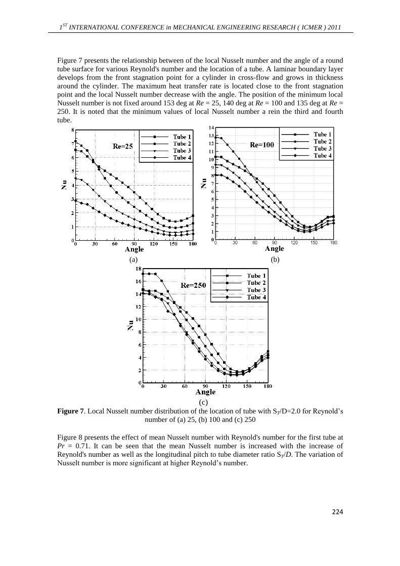
Figure 7 presents the relationship between of the local Nusselt number and the angle of a round
tube surface for various Reynold's number and the location of a tube. A laminar boundary layer
develops from the front stagnation point for a cylinder in cross-flow and grows in thickness
around the cylinder. The maximum heat transfer rate is located close to the front stagnation
point and the local Nusselt number decrease with the angle. The position of the minimum local
Nusselt number is not fixed around 153 deg at Re = 25, 140 deg at Re = 100 and 135 deg at Re =
250. It is noted that the minimum values of local Nusselt number a rein the third and fourth
tube.
(a) (b)
(c)
Figure 7. Local Nusselt number distribution of the location of tube with ST/D=2.0 for Reynold’s
number of (a) 25, (b) 100 and (c) 250
Figure 8 presents the effect of mean Nusselt number with Reynold's number for the first tube at
Pr = 0.71. It can be seen that the mean Nusselt number is increased with the increase of
Reynold's number as well as the longitudinal pitch to tube diameter ratio ST/D. The variation of
Nusselt number is more significant at higher Reynold’s number.

1ST
INTERNATIONAL CONFERENCE in MECHANICAL ENGINEERING RESEARCH ( ICMER ) 2011
225
Figure 8. Variation of mean Nusselt number with Re for the first tube at Pr = 0.71
5. Conclusions
The flow and heat transfer tubes in the regulation of cross-flow is of great importance in many
engineering applications. The two-dimensional steady-state and incompressible laminar flow for
staggered tube arrays in cross-flow is investigated numerically. A finite difference method is
numerically used to solve the governing Navier-Stokes and energy equations. The results show
that the behavior of flow and heat transfer of the first tube is similar to the behavior of flow and
heat transfer of a single tube. The local Nusselt number is increases by increases the
longitudinal pitch to tube diameter ratios and decreasing the angle of the surface tube. The
average Nu number increases by increases Reynolds number or by increases the longitudinal
pitch to tube diameter ratios. The form of temperature distribution is affected by Reynolds
number.
Acknowledgements
The authors would like to thank Universiti Malaysia Pahang for providing laboratory facilities
and financial support under Doctoral Grant scheme.
References
[1] Bejan A 1995 Convection Heat Transfer New York: John Wiley.
[2] Buyruk E 1999 Heat transfer and flow structures around circular cylinders in cross-
flow Tr. J. of Engineering and Environmental Science 23 299-315.
[3] Buyruk E 2002 Numerical study of heat transfer characteristics on tandem cylinders
inline and staggered tube banks in cross-flow of air International Communica-tions
in Heat and Mass Transfer 29 355-366.
[4] Buyruk E, Johnson M W, Owen I 1998 Numerical and experimental study of flow
and heat transfer around a tube in cross-flow at low Reynolds number International
Journal of Heat and Fluid Flow 19 223-232.
[5] Chang Y, Beris A N, Michaelides E E 1989 A numerical study of heat and
momentum transfer for flexible tube bundles in cross flow International Journal of
Heat and Mass Transfer 32 2027-2036.

1ST
INTERNATIONAL CONFERENCE in MECHANICAL ENGINEERING RESEARCH ( ICMER ) 2011
226
[6] Chen C J, Wung T S 1989 Finite analytic solution of convective heat transfer for
tube arrays in cross-flow: Part II-Heat transfer analysis Journal of Heat Transfer
111 641-648.
[7] Fowler A J, Bejan A 1994 Forced convection in banks of inclined cylinders at low
Reynolds numbers International Journal of Heat and Fluid Flow 15 90-99.
[8] Incropera F P, Dewitt D P 1996 Fundamentals of heat and mass transfer New
York: John Wiley.
[9] Kaptan Y, Buyruk E, Ecder A 2008 Numerical investigation of fouling on cross-
flow heat exchanger tubes with conjugated heat transfer approach. International
Communications in Heat and Mass Transfer 35 1153-1158.
[10] Khan W A, Culham J R, Yovanovich M M 2006 Convection heat transfer from
tube banks in cross-flow: analytical approach International Journal of Heat and
Mass Transfer 49 4831-4838.
[11] Liang C, Papadakis G 2007 Large eddy simulation of cross-flow through a
staggered tube bundle at subcritical Reynolds number Journal of Fluids and
Structures 23 1215-1230.
[12] Mandhani V K, Chhabra R P, Eswaran V 2002 Forced convection heat transfer in
tube banks in cross-flow Chemical Engineering Science 57 379-391.
[13] Marchi C H, Hobmeir M A 2007 Numerical solution of staggered circular tubes
in two-dimensional laminar forced convection J. of the Braz. Soc. of Mech. Sci. &
Eng, XXIX 42-48.
[14] Matos R S, Vargas J V C, Laursen T A, Bejan A 2004 Optimally staggered finned
circular and elliptic tubes in forced convection International Journal of Heat and
Mass Transfer 47 1347-1359.
[15] Matos R S, Vargas J V C, Laursen T A, Saboya F E M 2001 Optimization study
and heat transfer comparison of staggered circular and elliptic tubes in forced
convection International Journal of Heat and Mass Transfer 44 3953-3961.
[16] Patankar S V 1980 Numerical heat transfer and fluid flow Hemisphere,
Washington, DC.
[17] Rahmani R, Mirzaee I, Shirvani H 2005 Computation of a laminar flow and heat
transfer of air for staggered tube arrays in cross-flow Iranian Journal of
Mechanical Engineering 6 19-33.
[18] Stanescu G, Fowler A J, Bejan A 1996 The optimal spacing of cylinders in free-
stream cross-flow forced convection International Journal of Heat and Mass
Transfer 39 311-317.
[19] Thompson J R, Warsi Z U A, Martin C W 1985 Numerical grid generation,
foundations and applications North-Holland, New York.
[20] Wang M, Georgiadis J G 1996 Conjugate forced convection in cross-flow over a
cylinder array with volumetric heating International Journal of Heat and Mass
Transfer 39 1351-1361.
[21] Wilson A S, Bassiouny M K 2000 Modeling of heat transfer for flow a cross tube
banks Chemical Engineering and Processing 39 1-14.
[22] Yoo S Y, Kwonb H K, Kim J H 2007 A study on heat transfer characteristics for
staggered tube banks in cross-flow Journal of Mechanical Science and Technology
21 505-512.
[23] Yuan Z X, Tao W Q, Wang Q W 1998 Numerical prediction for laminar forced
convection heat transfer in parallel-plate channels with stream wise-periodic rod
disturbances Int. J. Numer. Meth. Fluids 28 1371–1387.
1ST
INTERNATIONAL CONFERENCE in MECHANICAL ENGINEERING RESEARCH ( ICMER ) 2011
227
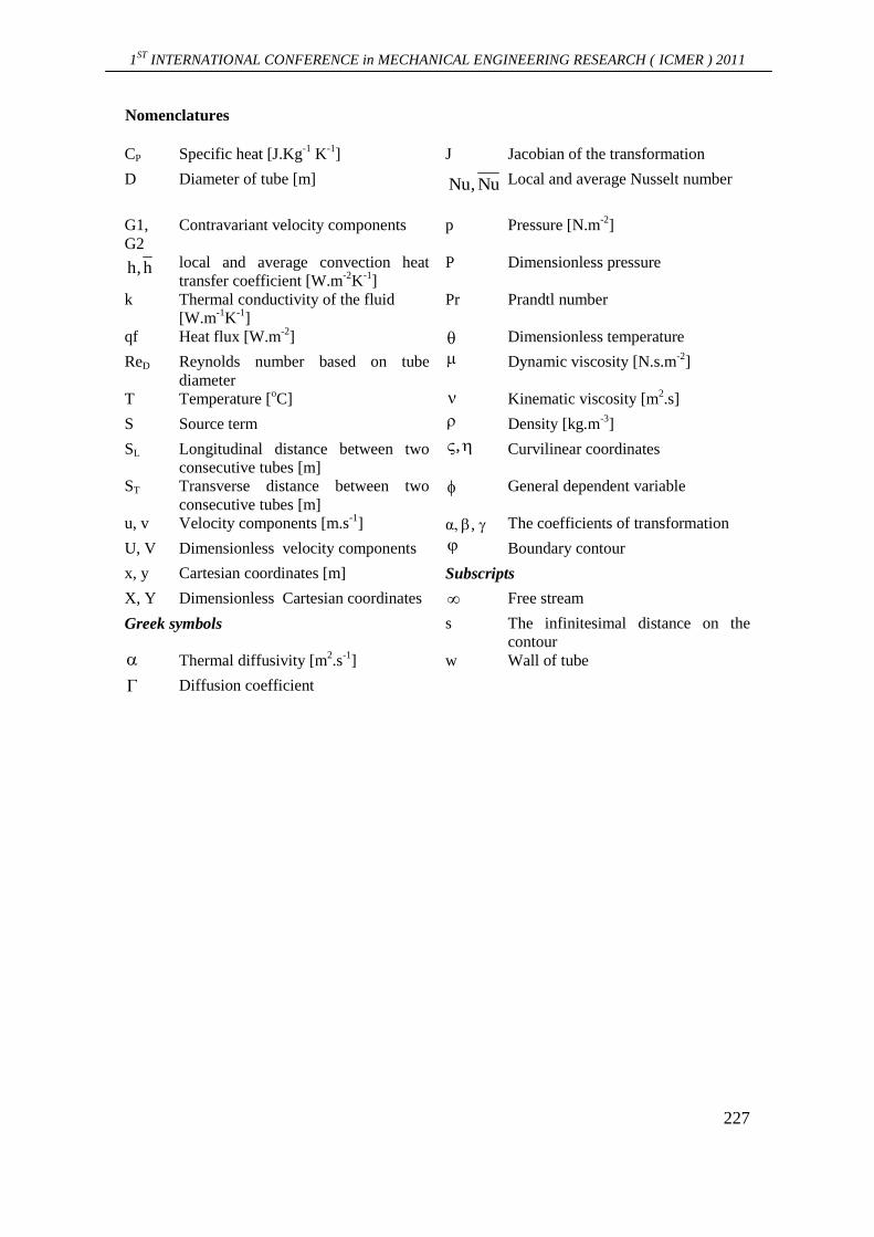
Nomenclatures
Jacobian of the transformation J Specific heat [J.Kg
-1 K
-1] CP
Local and average Nusselt number Nu, Nu
Diameter of tube [m] D
Pressure [N.m-2
] p Contravariant velocity components G1,
G2
Dimensionless pressure P local and average convection heat
transfer coefficient [W.m-2
K-1
] h,h
Prandtl number Pr Thermal conductivity of the fluid
[W.m-1
K-1
]
k
Dimensionless temperature Heat flux [W.m-2
] qf
Dynamic viscosity [N.s.m-2
] Reynolds number based on tube
diameter
ReD
Kinematic viscosity [m2.s] Temperature [
oC] T
Density [kg.m-3
] Source term S
Curvilinear coordinates , Longitudinal distance between two
consecutive tubes [m]
SL
General dependent variable Transverse distance between two
consecutive tubes [m]
ST
The coefficients of transformation α, , Velocity components [m.s-1
] u, v
Boundary contour Dimensionless velocity components U, V
Subscripts Cartesian coordinates [m] x, y
Free stream Dimensionless Cartesian coordinates X, Y
The infinitesimal distance on the
contour
s Greek symbols
Wall of tube w Thermal diffusivity [m2.s
-1]
Diffusion coefficient