a p4-based 5g user plane function
TRANSCRIPT
A P4-based 5G User Plane Function
Robert MacDavid∗, Carmelo Cascone†, Pingping Lin†, Badhrinath Padmanabhan†,Ajay Thakur†, Larry Peterson†, Jennifer Rexford∗, Oguz Sunay†
Princeton University∗, Open Networking Foundation†
ABSTRACTThe demands on mobile networks are constantly evolving, but de-signing and integrating new high-speed packet processing remainsa challenge due to the complexity of requirements and opacityof protocol specifications. 5G data planes should be implementedin programmable hardware for both speed and flexibility, and ex-tending or replacing these data planes should be painless. In thispaper we implement the 5G data plane using two P4 programs:one that acts as a open-source model data plane to simplify theinterface with the control plane, and one to run efficiently on hard-ware switches to minimize latency and maximize bandwidth. Themodel data plane enables testing changes made to the control planebefore integrating with a performant data plane, and vice versa.The hardware data plane implements the fast path for device traffic,and makes use of microservices to implement functions that high-speed switch hardware cannot do. Our data plane implementationis currently in limited deployment on three university campuseswhere it is enabling new research on mobile networks.
CCS CONCEPTS• Networks → Mobile networks; Programmable networks;Middle boxes / network appliances.
KEYWORDS5G, P4, Mobile networking, Programmable dataplanesACM Reference Format:Robert MacDavid, Carmelo Cascone, Pingping Lin, Badhrinath Padmanab-han, Ajay Thakur, Larry Peterson, Jennifer Rexford, Oguz Sunay. 2021. AP4-based 5G User Plane Function. In The ACM SIGCOMM Symposium onSDN Research (SOSR) (SOSR ’21), September 20–21, 2021, Virtual Event, USA.ACM, New York, NY, USA, 7 pages. https://doi.org/10.1145/3482898.3483358
1 INTRODUCTIONThe emergence of 5G promises high speed and low latency, enablinga wide range of innovative applications like Internet of Things (IoT)and augmented/virtual reality. As a result, many organizations—from global carriers and cloud providers to university campusesand small businesses—want to deploy their own 5G networks, andcustomize them for their users and applications. Historically, mo-bile network technology has been closed and vertically integrated,
Permission to make digital or hard copies of all or part of this work for personal orclassroom use is granted without fee provided that copies are not made or distributedfor profit or commercial advantage and that copies bear this notice and the full citationon the first page. Copyrights for components of this work owned by others than ACMmust be honored. Abstracting with credit is permitted. To copy otherwise, or republish,to post on servers or to redistribute to lists, requires prior specific permission and/or afee. Request permissions from [email protected] ’21, September 20–21, 2021, Virtual Event, USA© 2021 Association for Computing Machinery.ACM ISBN 978-1-4503-9084-2/21/09. . . $15.00https://doi.org/10.1145/3482898.3483358
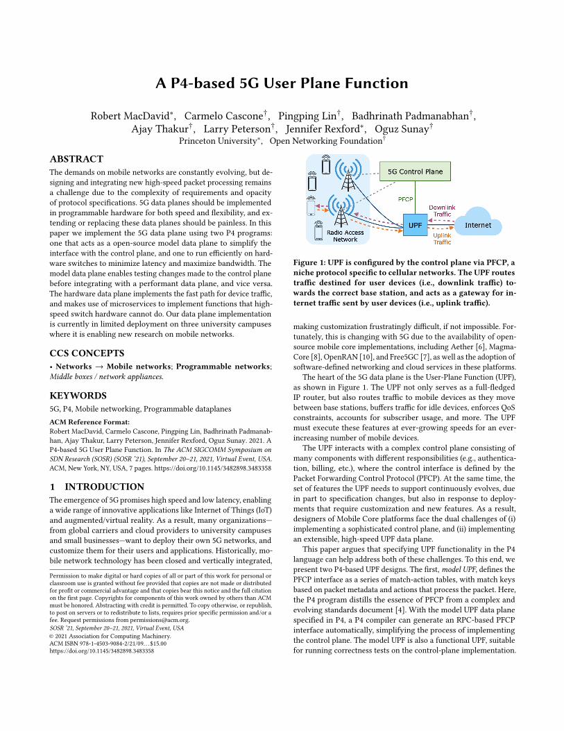
Figure 1: UPF is configured by the control plane via PFCP, aniche protocol specific to cellular networks. The UPF routestraffic destined for user devices (i.e., downlink traffic) to-wards the correct base station, and acts as a gateway for in-ternet traffic sent by user devices (i.e., uplink traffic).
making customization frustratingly difficult, if not impossible. For-tunately, this is changing with 5G due to the availability of open-source mobile core implementations, including Aether [6], Magma-Core [8], OpenRAN [10], and Free5GC [7], as well as the adoption ofsoftware-defined networking and cloud services in these platforms.
The heart of the 5G data plane is the User-Plane Function (UPF),as shown in Figure 1. The UPF not only serves as a full-fledgedIP router, but also routes traffic to mobile devices as they movebetween base stations, buffers traffic for idle devices, enforces QoSconstraints, accounts for subscriber usage, and more. The UPFmust execute these features at ever-growing speeds for an ever-increasing number of mobile devices.
The UPF interacts with a complex control plane consisting ofmany components with different responsibilities (e.g., authentica-tion, billing, etc.), where the control interface is defined by thePacket Forwarding Control Protocol (PFCP). At the same time, theset of features the UPF needs to support continuously evolves, duein part to specification changes, but also in response to deploy-ments that require customization and new features. As a result,designers of Mobile Core platforms face the dual challenges of (i)implementing a sophisticated control plane, and (ii) implementingan extensible, high-speed UPF data plane.
This paper argues that specifying UPF functionality in the P4language can help address both of these challenges. To this end, wepresent two P4-based UPF designs. The first,model UPF, defines thePFCP interface as a series of match-action tables, with match keysbased on packet metadata and actions that process the packet. Here,the P4 program distills the essence of PFCP from a complex andevolving standards document [4]. With the model UPF data planespecified in P4, a P4 compiler can generate an RPC-based PFCPinterface automatically, simplifying the process of implementingthe control plane. The model UPF is also a functional UPF, suitablefor running correctness tests on the control-plane implementation.
SOSR ’21, September 20–21, 2021, Virtual Event, USA MacDavid, et al.
Running on a software switch, the model UPF supports developingcontrol-plane software in emulation environments like Mininet [9],without developers requiring access to special-purpose data-planehardware. Additionally, recent research focused on automaticallygenerating test cases based on P4 programs would allow the modelUPF to be used to test other UPF implementations [16, 21].
The model UPF P4 program serves as a useful starting pointfor creating full-fledged UPF implementations for specific hard-ware targets. This leads to our second design, the performant UPF,which runs on the Intel Tofino programmable data-plane switch.While earlier open-source 5G platforms implemented the UPF en-tirely in software, hardware network interface cards (NICs) andswitches offer higher speed and lower power. The performant UPFP4 program must grapple with the realities of limited data-planeresources. Some match-action tables in the model UPF are too large,requiring optimizations that break “wide" match-action tables intoa collection of smaller tables. Other capabilities of a performant UPFcannot be expressed in P4, or cannot be supported in high-speedpacket-processing hardware at all. Here, we rely on microservicesto support certain functionality, such as buffering traffic for idlemobile devices. The end result is an efficient system with a hard-ware data plane processing most traffic, an a set of microserviceshandling other UPF functionality.
Many existing works aim to solve issues present in both LTEand 5G such as control signalling load [19, 22, 24], fault toler-ance [14, 20], and software data-plane performance [23] but fewseek to implement the data-plane in hardware, although there areproprietary P4-based solutions [2]. TurboEPC [24] implementsLTE’s equivalent of the UPF in P4 switches and reduces control-plane load by processing some common control messages in thedata-plane, but it requires control plane modification and does notdiscuss features like idle buffering that are currently unsupportedby P4. Aghdai et. al [13] introduce a new P4-based network func-tion to the mobile core for reducing latency between user devicesand edge services, but they do not implement the UPF or its LTEequivalent.
The remainder of the paper is organized as follows. §2 presentsbackground on the User Plane Function and the control-plane in-terface. §3 presents the model UPF, including how to synthesize thecontrol-plane interface and specify the data plane. We release themodel UPF P4 program as open source, to serve as executable UPFdocumentation for the community. [12] §4 describes the perfor-mant UPF for the Intel Tofino switch, including how to work withinlimited data-plane memory and interface to an external bufferingmicroservice. §5 presents our experiences with the two UPFs in theAether mobile core platform (including deployments on universitycampuses), and §6 discusses future research directions.
2 USER PLANE FUNCTION (UPF)The User Plane Function (UPF) connects the base stations of theRadio Access Network (RAN) to the Internet. It performs packetprocessing for user devices, including supportingmobility, bufferingfor idle devices, traffic accounting, and quality-of-service based onrules configured by the control plane, as summarized in Table 1.
Traffic classification: Each packet corresponds to a user deviceattached to the cellular network. The UPF associates a packet withthe corresponding user device and traffic class, based on Packet
Rule Rule Key(s) Rule ParametersPacket Detection Rule IP Address, 5-Tuple,
Tunnel Headers,Endpoint DNS NameRegex
FAR-ID, QER-ID, URR-ID,Decapsulation Flag
Forwarding Action Rule FAR-ID (Forward, Buffer, Notify)Flags, Tunnel Headers (op-tional), BAR-ID (optional)
Buffering Action Rule BAR-ID Buffer Depth, Buffer DurationUsage Reporting Rule URR-ID Counter Index, Reporting
Frequency or ThresholdQoS Enforcement Rule QER-ID QoS Flow ID (QFI), Guaran-
teed BitRate, Maximum Bi-tRate
Table 1: The rules a 5G control plane uses to configure a UPF,the match keys used to look up a rule, and the parametersloaded into a packet’s metadata by said rule. Italicized fieldsare either scaffolded or not present in the model UPF.
Detection Rules (PDRs). A PDR may simply match the device’s IPaddress, or consider tunnel headers, the five-tuple, or even the do-main name of the other end-point. The matching PDR determineshow other parts of the UPF process the packet. Each attached userdevice has at least two PDRs, for uplink and downlink traffic, re-spectively, and possibly more to support multiple traffic classes(e.g., for different QoS levels, pricing plans, etc.). The control planeinstalls, changes, and removes PDRs when a device attaches, movesto another base station, and detaches, respectively.
Mobility and packet forwarding:User devices connect to newbase stations as the user moves. To tunnel downlink packets to theright base station, the UPF applies a Forwarding Action Rule (FAR)identified by the PDR during packet classification. The FAR fordownlink traffic indicates the tunnel header field and the IP addressof the base station. More generally, a FAR specifies a set of actions(using flags) to apply to the packet, including tunneling, forwarding,buffering, and notifying the control plane. For example, a typicalFAR for uplink traffic contains only a ‘forward’ flag, signifying thatthe packet is permitted to enter the UPF’s IP router functionality.In contrast, the ‘notify’ flag sends an alert to the control plane towake an idle device. FARs are installed and removed when a deviceattaches or detaches, respectively, and the downlink FAR changeswhen the device moves, goes idle, or wakes.
Buffering for idle devices:When a user device goes idle, theUPF buffers downlink traffic that arrives for that device until itreawakens; this feature is increasingly important as battery opti-mizations and limited radio spectrum push devices to spend moretime idle. When traffic first arrives, the UPF sends an “DownlinkData Notification” alert to the control plane, which triggers the basestation to attempt to wake the device. Once the device awakens, theUPF releases the buffered traffic and resumes normal forwarding.The buffering and notification functions are activated by modifyinga FAR to include ‘buffer’ and ‘notify’ flags. An additional set ofBuffering Action Rules (BARs) decide settings like the maximumnumber of packets (and the maximum duration) to buffer. The iden-tifier of the BAR to use is determined by the FAR that triggeredbuffering. If no BAR is provided, default settings are assumed.
Traffic accounting: The UPF sends usage reports for each userdevice to the control plane. These reports include counts of thepackets sent and received by the UPF for both the uplink and down-link traffic for each user device and traffic class. Service providersuse these measurements to limit and bill their customers separately

A P4-based 5G User Plane Function SOSR ’21, September 20–21, 2021, Virtual Event, USA
for upload and download usage. The control plane installs and re-moves Usage Reporting Rules (URRs) when the device attaches anddetaches, respectively. Each URR includes parameters specifyingwhether usage reports should be sent periodically or when a quotais exceeded. Typically a device has two URRs, one for uplink anddownlink usage, respectively. If a user’s plan includes special treat-ment for certain types of traffic, an additional URR is created foreach traffic class (e.g., to support plans with free VoIP/video calls).
Quality-of-Service: The UPF guarantees a minimum amountof available bandwidth and enforces a bandwidth cap for eachuser device, for uplink and downlink packets for each traffic class.These parameters are decided by per-device Quality EnforcementRules (QERs). The identifier of the associated QER is determinedby the PDR in the traffic-classification process. The control planeinstalls and removes QERs when a device attaches and detaches,respectively, and are modified according to operator-defined eventssuch as when the network becomes more or less congested, the userdevice exceeds a quota, or the network policy changes (e.g., theuser signs up for a new pricing plan). The UPF can perform trafficpolicing to enforce the bandwidth cap, as well as packet schedulingto ensure a minimum bandwidth in conjunction with admissioncontrol in the control plane.
3 THE MODEL UPFThe PFCP protocol used for communication between the controlplane and the UPF can be difficult to understand, even though therules it installs are actually simple match-action rules, as summa-rized in Table 1. Additionally, documentation on the operationsapplied to a packet by the UPF and the order in which they ap-ply are scattered across the 5G specifications. To address both ofthese issues, we proposemodeling the UPF with a P4 program. Sucha model would provide unambiguous, executable documentationon the UPF and, with the addition of P4Runtime, provides a sim-ple control-plane interface as well. More specifically, we have twoobjectives in the implementation of a model UPF:
(1) The model UPF should serve as an interface that the 5Gcontrol plane can expect a data-plane implementation toexpose. Developers creating their own data plane need onlypresent the same interface as the model UPF in order tointegrate with the control plane. Implementing the sameinterface also means that testing infrastructure can be reusedto verify the behavior of a new UPF.
(2) The model UPF should implement a minimally functionalUPF, to act as a valid and executable data plane suitable forrunning correctness tests on the 5G control plane in theabsence of a more sophisticated data-plane implementation.The implemented functions can also serve as behavioralreferences for implementers of new UPFs.
3.1 Synthesizing the Control-Plane InterfaceP4 is a language for specifying packet-processing pipelines, butit does not provide any means for the control plane to configurethose pipelines at runtime. P4Runtime fills this need. P4Runtime isan RPC (Remote Procedure Call) protocol that allows a P4Runtimeclient running in the control plane to read and write table entries,read counter values, and install new P4 programs from a P4Runtime
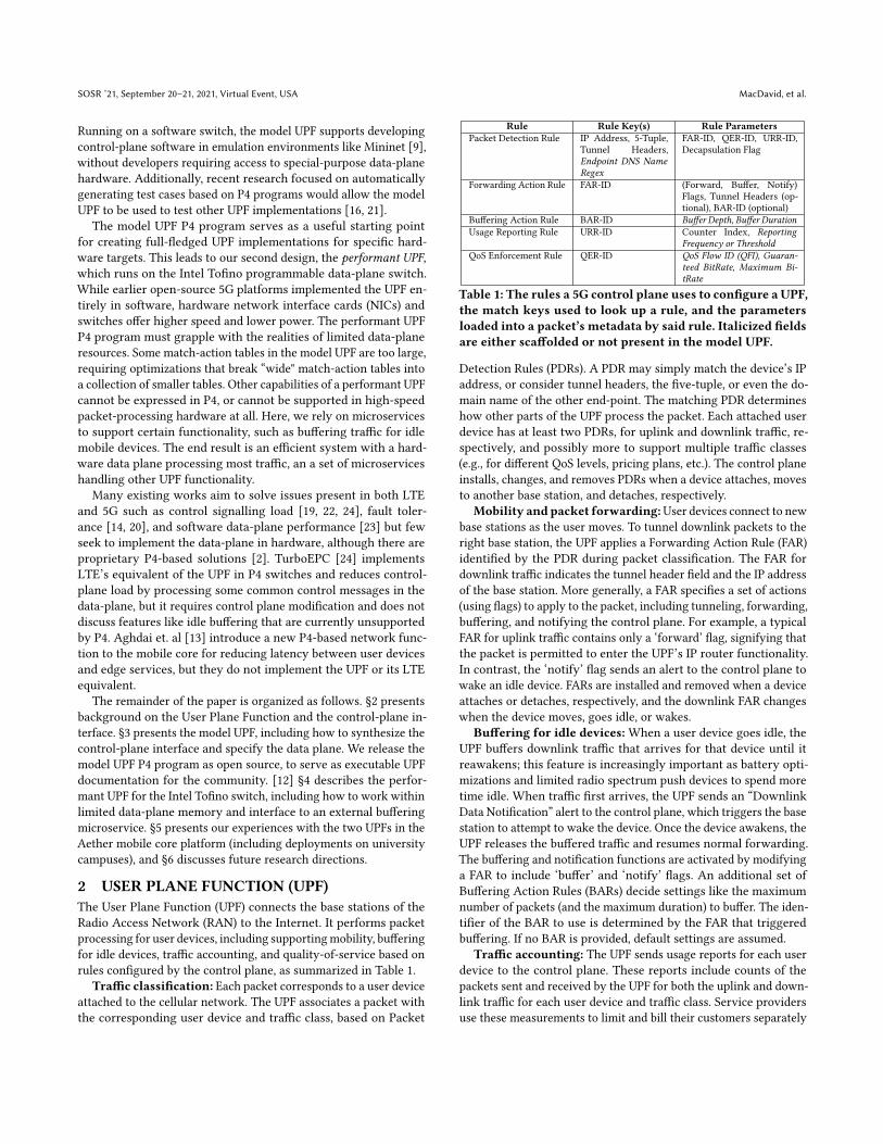
Figure 2: The model UPF P4 pipeline
server running on a data plane 1. The format of table and counterreads and writes is determined by a p4info file, akin to a headerfile, that is generated when a P4 program is compiled. For example,for each table in a P4 program, the p4info contains a description ofthe table name, match keys, action names, and action parameters,but not details of the operations or packet modifications performedby the table. A P4Runtime client can install an entry into a table bysending a write request message containing a table entry matchingthe format specified in the p4info. If we create P4 representationsof every UPF feature, P4Runtime automatically gives us a controlinterface to those representations.
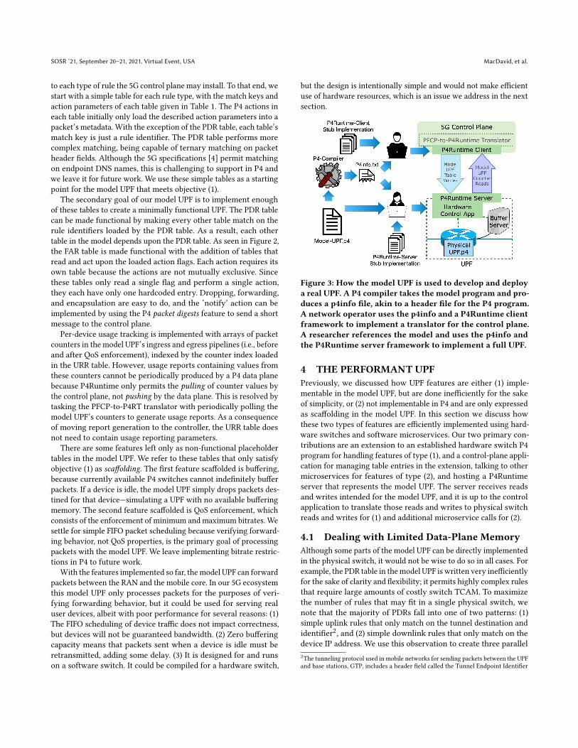
To implement a real UPF that uses the model UPF interface, theimplementer must only implement a P4Runtime server that acceptsmessages matching the p4info of the model UPF, as shown in Fig-ure 3. Since P4Runtime is based on gRPC, client and server stub im-plementations can be automatically generated from the P4Runtimeprotocol specification for a variety of popular languages. The stubimplementations take care of message serialization and connectionmanagement; the implementer need only worry about reading andwriting message objects, accelerating the development and inte-gration of new UPFs. However, to support these new UPFs, the5G control plane must speak P4Runtime instead of PFCP. This ishandled by the implementation of a PFCP-to-P4Runtime transla-tion microservice, which must be done once and can be reused bydifferent control plane implementations without modification.
An important note here is that the data plane driven by theP4Runtime server need not exactly adhere to the P4 program pre-sented to the client. For example, the data plane may consist of twoparallel ASICs, eachwith onematch-action table, but the P4Runtimeserver may choose to abstract them as a single device with a sin-gle table. In such a setting where the data plane does not matchthe p4info presented to clients, it is up to the server to translatereads/writes to the representative P4 program into reads/writes tothe true data plane. Although this translation currently must bemanually implemented, there is research interest in automatingsuch translations [16].
3.2 Specifying the Model UPF Data PlaneIn order to meet objective (1), we need a P4 program that, whencompiled, generates a set of P4Runtime messages that directly map1The server is not exactly “on” the data plane. Modern switches are typically comprisedof a both a CPU and a packet-processing ASIC. The ASIC is configured via the PCIbus by control processes (like a P4Runtime server) running on the CPU.
SOSR ’21, September 20–21, 2021, Virtual Event, USA MacDavid, et al.
to each type of rule the 5G control plane may install. To that end, westart with a simple table for each rule type, with the match keys andaction parameters of each table given in Table 1. The P4 actions ineach table initially only load the described action parameters into apacket’s metadata. With the exception of the PDR table, each table’smatch key is just a rule identifier. The PDR table performs morecomplex matching, being capable of ternary matching on packetheader fields. Although the 5G specifications [4] permit matchingon endpoint DNS names, this is challenging to support in P4 andwe leave it for future work. We use these simple tables as a startingpoint for the model UPF that meets objective (1).
The secondary goal of our model UPF is to implement enoughof these tables to create a minimally functional UPF. The PDR tablecan be made functional by making every other table match on therule identifiers loaded by the PDR table. As a result, each othertable in the model depends upon the PDR table. As seen in Figure 2,the FAR table is made functional with the addition of tables thatread and act upon the loaded action flags. Each action requires itsown table because the actions are not mutually exclusive. Sincethese tables only read a single flag and perform a single action,they each have only one hardcoded entry. Dropping, forwarding,and encapsulation are easy to do, and the ‘notify’ action can beimplemented by using the P4 packet digests feature to send a shortmessage to the control plane.
Per-device usage tracking is implemented with arrays of packetcounters in the model UPF’s ingress and egress pipelines (i.e., beforeand after QoS enforcement), indexed by the counter index loadedin the URR table. However, usage reports containing values fromthese counters cannot be periodically produced by a P4 data planebecause P4Runtime only permits the pulling of counter values bythe control plane, not pushing by the data plane. This is resolved bytasking the PFCP-to-P4RT translator with periodically polling themodel UPF’s counters to generate usage reports. As a consequenceof moving report generation to the controller, the URR table doesnot need to contain usage reporting parameters.
There are some features left only as non-functional placeholdertables in the model UPF. We refer to these tables that only satisfyobjective (1) as scaffolding. The first feature scaffolded is buffering,because currently available P4 switches cannot indefinitely bufferpackets. If a device is idle, the model UPF simply drops packets des-tined for that device—simulating a UPF with no available bufferingmemory. The second feature scaffolded is QoS enforcement, whichconsists of the enforcement of minimum and maximum bitrates. Wesettle for simple FIFO packet scheduling because verifying forward-ing behavior, not QoS properties, is the primary goal of processingpackets with the model UPF. We leave implementing bitrate restric-tions in P4 to future work.
With the features implemented so far, themodel UPF can forwardpackets between the RAN and the mobile core. In our 5G ecosystemthis model UPF only processes packets for the purposes of veri-fying forwarding behavior, but it could be used for serving realuser devices, albeit with poor performance for several reasons: (1)The FIFO scheduling of device traffic does not impact correctness,but devices will not be guaranteed bandwidth. (2) Zero bufferingcapacity means that packets sent when a device is idle must beretransmitted, adding some delay. (3) It is designed for and runson a software switch. It could be compiled for a hardware switch,
but the design is intentionally simple and would not make efficientuse of hardware resources, which is an issue we address in the nextsection.
Figure 3: How the model UPF is used to develop and deploya real UPF. A P4 compiler takes the model program and pro-duces a p4info file, akin to a header file for the P4 program.A network operator uses the p4info and a P4Runtime clientframework to implement a translator for the control plane.A researcher references the model and uses the p4info andthe P4Runtime server framework to implement a full UPF.
4 THE PERFORMANT UPFPreviously, we discussed how UPF features are either (1) imple-mentable in the model UPF, but are done inefficiently for the sakeof simplicity, or (2) not implementable in P4 and are only expressedas scaffolding in the model UPF. In this section we discuss howthese two types of features are efficiently implemented using hard-ware switches and software microservices. Our two primary con-tributions are an extension to an established hardware switch P4program for handling features of type (1), and a control-plane appli-cation for managing table entries in the extension, talking to othermicroservices for features of type (2), and hosting a P4Runtimeserver that represents the model UPF. The server receives readsand writes intended for the model UPF, and it is up to the controlapplication to translate those reads and writes to physical switchreads and writes for (1) and additional microservice calls for (2).
4.1 Dealing with Limited Data-Plane MemoryAlthough some parts of the model UPF can be directly implementedin the physical switch, it would not be wise to do so in all cases. Forexample, the PDR table in themodel UPF is written very inefficientlyfor the sake of clarity and flexibility; it permits highly complex rulesthat require large amounts of costly switch TCAM. To maximizethe number of rules that may fit in a single physical switch, wenote that the majority of PDRs fall into one of two patterns: (1)simple uplink rules that only match on the tunnel destination andidentifier2, and (2) simple downlink rules that only match on thedevice IP address. We use this observation to create three parallel2The tunneling protocol used in mobile networks for sending packets between the UPFand base stations, GTP, includes a header field called the Tunnel Endpoint Identifier
A P4-based 5G User Plane Function SOSR ’21, September 20–21, 2021, Virtual Event, USA
PDR tables in the physical switch: one for common-case uplink rulesthat exactly matches (using the relatively plentiful switch SRAMinstead of TCAM) on two tunnel header fields, one for common-case downlink rules that exactly matches on only the IP destination,and one small, inefficient table that is as flexible as the model PDRtable and will only be used for rare, complex rules. The control appis responsible for mapping model PDR table entries to the mostsuitable hardware table. If more PDR patterns are observed in thefuture, additional tables optimized for each pattern can be created.
4.2 Interfaces to Buffering MicroserviceWhen packets arrive from the internet destined for an idle device,the UPF should buffer packets on behalf of that device and send analert to the 5G control plane to awaken it. Currently available hard-ware P4 switches are designed for data centers and thus do not havelarge buffers or the ability to hold packets indefinitely. To cover thisfeature gap, we use a buffering microservice, controllable via gRPC,that is provided by our chosen 5G ecosystem. The microserviceindefinitely holds any packets that it receives, and releases themback into the network when a control signal is received via gRPC.
When a device goes idle, the control plane installs a FAR in themodel UPF with the ‘buffer’ flag set. The control app translatesthis model FAR entry to flow rules in the physical UPF P4 modulethat redirect packets destined for the idle device to the bufferingmicroservice. Packets are redirected to the microservice withoutmodifying the IP headers by placing them in a tunnel. The tunnelingprotocol used for sending data to the microservice is the same asthat used to send packets to 5G base stations, which allows thehardware switch and control app to treat the buffering microserviceas just another base station. Additionally, not implementing anothertunnel protocol in the switches reduces resource usage in the packetparser and deparsers, which is an important concern for industrialnetwork deployments that have continuously growing feature lists.
When the first packet of a new flow arrives at the bufferingmicroservice, the microservice sends an alert to any currently con-nected gRPC clients that a new flow is being buffered. The controlapp listens for this event, and translates it to an alert to the 5G con-trol plane that the device corresponding to that flow should wakeup. The alert is sent as a ‘packet digest’ emanating from the modelUPF. When a device wakes up, the control plane modifies the FARinstalled in the model UPF by unsetting the ‘buffer’ flag and settingthe ‘tunnel’ flag. When this specific transition occurs, the controlapp sends a gRPC signal to the buffering microservice, instructingit to release all packets for that device back to the physical switch.Packets arriving at the physical switch from the buffering microser-vice skip the portion of the UPF module they encountered beforebuffering, to give the illusion of being buffered in the middle ofthe switch. Their processing resumes at the tunneling stage, wherethey are encapsulated and routed to the appropriate base station.
4.3 QoS and Usage ReportingQERs cannot be implemented in the model UPF because P4 doesnot support the expression of packet schedulers. However, cur-rently available hardware P4 switches have simple schedulers with
(TEID), which can be used by PDRs to map packets to devices without parsing innerheaders.
programmable weights and priorities, programmed using runtimeinterfaces unrelated to P4. It may be possible to approximately en-force bitrate guarantees and limits using this scheduler with anapproach like Rotating Strict Priority [25], but we leave that for fu-ture work and for now simply map the QoS class identifiers loadedby the QERs to one of the available queues.
Usage counters for generating Usage Reporting Rules are imple-mented in the hardware switches identically to how they appearin the model UPF, with counter arrays in the switches’ ingress andegress. When the PFCP-to-P4 translation microservice requestscounter values from the model UPF, the control application simplypolls the hardware switch counters and relays the response.
5 DEPLOYMENT EXPERIENCEOur prototype has been included in the Aether [6] 5G mobile coreecosystem and is currently in limited deployment on three univer-sity campuses, where it is being used for research on improvingthe reliability and performance of mobile networks.
5.1 Prototype Implementation DetailsThe hardware control application (see Figure 3) responsible fortranslation between the model and hardware UPFs is written asa Java application for a network controller OS [11] and consistsof ~5,200 lines of code. The Model UPF is written in ~760 linesof P4 code for the Behavioral Model version 2 (BMv2) softwareswitch. The hardware UPF was written in ~400 lines of P4 code as anextension for an established leaf-spine fabric P4 switch program [5].In our campus deployment, the performant UPF is installed in theleaf of a 2x2 leaf-spine topology of 6.4 Tbps Edgecore Wedge100BF-32X and 32QS switches that use the Intel TofinoASIC. The leaf-spinetopology connects a RAN of small cells to compute nodes and theinternet.
Currently, the hardware UPF pipeline uses less than 15% of theTofino chip’s total available SRAM memory to support 17,500 userdevices. The primary sources for the SRAM usage are the PDRtables, FAR tables, and URR counters, each of which must havecapacity equal to twice the maximum number of connected devices(since each device has at least two of each rule—one uplink and onedownlink). The program has not been aggressively optimized andachieving support for several times more devices is likely, althoughmemory will still become a limitation long before software switchscales are reached. Potential directions for supporting more devicesin the face of memory limitations are discussed in Section 6.
5.2 Testing of the UPFsFor unit testing of both the UPF programs, we use the Python-basedPacket Testing Framework (PTF). In a PTF unit test, a P4 programis installed in a software switch, a fixed set of P4Runtime messagesare sent to the switch to populate the tables, and then packetsare sent through the switch. The test is passed if packets outputby the switch adhere to expectations. In our setting, the packetsinjected match the format of data traffic to and from a 5G RAN.There are unit tests for detached, attached, and idle device states.For the model program, the software switch used is BMv2. For thehardware program, it is the Intel Tofino ASIC simulator providedby the Tofino SDK. Functional equivalence between the model and
SOSR ’21, September 20–21, 2021, Virtual Event, USA MacDavid, et al.
hardware UPF programs is empirically checked by writing unittests that inject and verify the same input and output packets inboth programs. There are currently ~550 lines of PTF-based unittests for the model UPF, and ~2600 lines of tests for the performantUPF, although many of these tests cover the non-UPF modules. Ifmore robust equivalence tests are needed, projects like Avenir [16]and p4pktgen [21] may be used in the future.
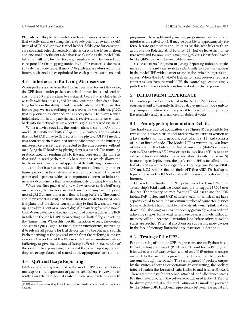
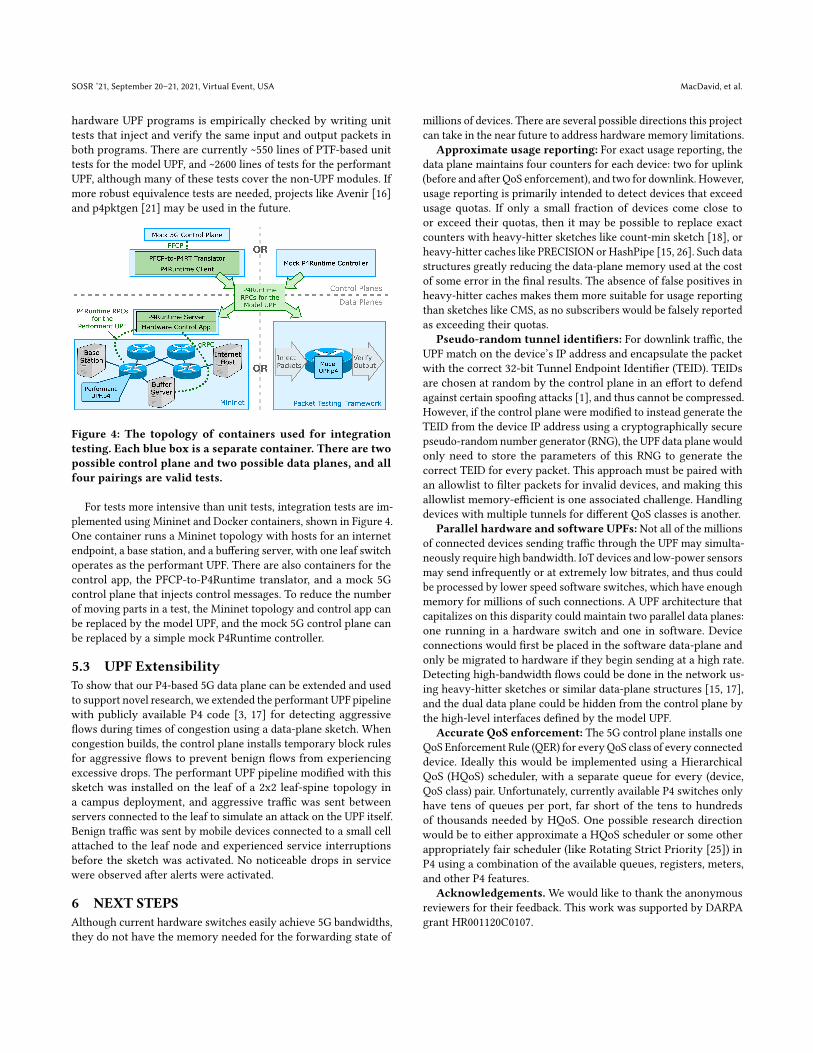
Figure 4: The topology of containers used for integrationtesting. Each blue box is a separate container. There are twopossible control plane and two possible data planes, and allfour pairings are valid tests.
For tests more intensive than unit tests, integration tests are im-plemented using Mininet and Docker containers, shown in Figure 4.One container runs a Mininet topology with hosts for an internetendpoint, a base station, and a buffering server, with one leaf switchoperates as the performant UPF. There are also containers for thecontrol app, the PFCP-to-P4Runtime translator, and a mock 5Gcontrol plane that injects control messages. To reduce the numberof moving parts in a test, the Mininet topology and control app canbe replaced by the model UPF, and the mock 5G control plane canbe replaced by a simple mock P4Runtime controller.
5.3 UPF ExtensibilityTo show that our P4-based 5G data plane can be extended and usedto support novel research, we extended the performant UPF pipelinewith publicly available P4 code [3, 17] for detecting aggressiveflows during times of congestion using a data-plane sketch. Whencongestion builds, the control plane installs temporary block rulesfor aggressive flows to prevent benign flows from experiencingexcessive drops. The performant UPF pipeline modified with thissketch was installed on the leaf of a 2x2 leaf-spine topology ina campus deployment, and aggressive traffic was sent betweenservers connected to the leaf to simulate an attack on the UPF itself.Benign traffic was sent by mobile devices connected to a small cellattached to the leaf node and experienced service interruptionsbefore the sketch was activated. No noticeable drops in servicewere observed after alerts were activated.
6 NEXT STEPSAlthough current hardware switches easily achieve 5G bandwidths,they do not have the memory needed for the forwarding state of
millions of devices. There are several possible directions this projectcan take in the near future to address hardware memory limitations.
Approximate usage reporting: For exact usage reporting, thedata plane maintains four counters for each device: two for uplink(before and after QoS enforcement), and two for downlink. However,usage reporting is primarily intended to detect devices that exceedusage quotas. If only a small fraction of devices come close toor exceed their quotas, then it may be possible to replace exactcounters with heavy-hitter sketches like count-min sketch [18], orheavy-hitter caches like PRECISION or HashPipe [15, 26]. Such datastructures greatly reducing the data-plane memory used at the costof some error in the final results. The absence of false positives inheavy-hitter caches makes them more suitable for usage reportingthan sketches like CMS, as no subscribers would be falsely reportedas exceeding their quotas.
Pseudo-random tunnel identifiers: For downlink traffic, theUPF match on the device’s IP address and encapsulate the packetwith the correct 32-bit Tunnel Endpoint Identifier (TEID). TEIDsare chosen at random by the control plane in an effort to defendagainst certain spoofing attacks [1], and thus cannot be compressed.However, if the control plane were modified to instead generate theTEID from the device IP address using a cryptographically securepseudo-random number generator (RNG), the UPF data plane wouldonly need to store the parameters of this RNG to generate thecorrect TEID for every packet. This approach must be paired withan allowlist to filter packets for invalid devices, and making thisallowlist memory-efficient is one associated challenge. Handlingdevices with multiple tunnels for different QoS classes is another.
Parallel hardware and software UPFs: Not all of the millionsof connected devices sending traffic through the UPF may simulta-neously require high bandwidth. IoT devices and low-power sensorsmay send infrequently or at extremely low bitrates, and thus couldbe processed by lower speed software switches, which have enoughmemory for millions of such connections. A UPF architecture thatcapitalizes on this disparity could maintain two parallel data planes:one running in a hardware switch and one in software. Deviceconnections would first be placed in the software data-plane andonly be migrated to hardware if they begin sending at a high rate.Detecting high-bandwidth flows could be done in the network us-ing heavy-hitter sketches or similar data-plane structures [15, 17],and the dual data plane could be hidden from the control plane bythe high-level interfaces defined by the model UPF.
Accurate QoS enforcement: The 5G control plane installs oneQoS Enforcement Rule (QER) for every QoS class of every connecteddevice. Ideally this would be implemented using a HierarchicalQoS (HQoS) scheduler, with a separate queue for every (device,QoS class) pair. Unfortunately, currently available P4 switches onlyhave tens of queues per port, far short of the tens to hundredsof thousands needed by HQoS. One possible research directionwould be to either approximate a HQoS scheduler or some otherappropriately fair scheduler (like Rotating Strict Priority [25]) inP4 using a combination of the available queues, registers, meters,and other P4 features.
Acknowledgements.We would like to thank the anonymousreviewers for their feedback. This work was supported by DARPAgrant HR001120C0107.

A P4-based 5G User Plane Function SOSR ’21, September 20–21, 2021, Virtual Event, USA
REFERENCES[1] 2017. Threats to Packet Core Security of P4 Networks. Retrieved June 9th, 2021
from https://positive-tech.com/expert-lab/research/epc-research/[2] 2019. The Kaloom 5G User Plane Function. Retrieved June 7th,
2021 from https://www.mbuzzeurope.com/wp-content/uploads/2020/02/Product-Brief-Kaloom-5G-UPF-v1.0.pdf
[3] 2020. ConQuest Github Repo. Retrieved June 15th, 2021 from https://github.com/Princeton-Cabernet/p4-projects/tree/master/ConQuest-tofino
[4] 2020. Interface between the Control Plane and the User Plane nodes. RetrievedApril 3rd, 2020 from https://portal.3gpp.org/desktopmodules/Specifications/SpecificationDetails.aspx?specificationId=3111
[5] 2020. The ONOS fabric.p4 switch. Retrieved June 16th, 2021from https://github.com/opennetworkinglab/onos/blob/master/pipelines/fabric/impl/src/main/resources/fabric.p4
[6] 2021. Aether Project. Retrieved June 6th, 2021 from https://aetherproject.org[7] 2021. Free5GC. Retrieved June 6th, 2021 from https://www.free5gc.org[8] 2021. Magma Core. Retrieved June 6th, 2021 from https://www.magmacore.org[9] 2021. Mininet. Retrieved June 10th, 2021 from http://mininet.org[10] 2021. O-RAN Alliance. Retrieved June 6th, 2021 from https://www.o-ran.org[11] 2021. ONOS Github Repo. Retrieved June 16th, 2021 from https://github.com/
opennetworkinglab/onos[12] 2021. UP4 Public Github Repo. Retrieved August 23rd, 2021 from https://github.
com/robertmacdavid/up4-abstract[13] Ashkan Aghdai, Mark Huang, David Dai, Yang Xu, and Jonathan Chao. 2018.
Transparent Edge Gateway for Mobile Networks. In 2018 IEEE 26th InternationalConference on Network Protocols (ICNP). 412–417. https://doi.org/10.1109/ICNP.2018.00057
[14] Mukhtiar Ahmad, Syed Usman Jafri, Azam Ikram, Wasiq Noor Ahmad Qasmi,Muhammad Ali Nawazish, Zartash Afzal Uzmi, and Zafar Ayyub Qazi. 2020. ALow Latency and Consistent Cellular Control Plane. In ACM SIGCOMM. 648–661.
[15] Ran Ben Basat, Xiaoqi Chen, Gil Einziger, and Ori Rottenstreich. 2020. DesigningHeavy-Hitter Detection Algorithms for Programmable Switches. IEEE/ACMTransactions on Networking 28, 3 (2020), 1172–1185. https://doi.org/10.1109/TNET.2020.2982739
[16] Eric Hayden Campbell, William T. Hallahan, Priya Srikumar, Carmelo Cascone,Jed Liu, Vignesh Ramamurthy, Hossein Hojjat, Ruzica Piskac, Robert Soulé, and
Nate Foster. 2021. Avenir: Managing Data Plane Diversity with Control Plane Syn-thesis. In USENIX Symposium on Networked Systems Design and Implementation.133–153.
[17] Xiaoqi Chen, Shir Landau Feibish, Yaron Koral, Jennifer Rexford, Ori Rottenstre-ich, Steven A Monetti, and Tzuu-Yi Wang. 2019. Fine-Grained Queue Measure-ment in the Data Plane. In ACM SIGCOMM Conference on Emerging NetworkingExperiments And Technologies. 15–29.
[18] Graham Cormode and S. Muthukrishnan. 2005. An Improved Data StreamSummary: The Count-Min Sketch and Its Applications. J. Algorithms 55, 1 (April2005), 58–75. https://doi.org/10.1016/j.jalgor.2003.12.001
[19] Ali Mohammadkhan, K.K. Ramakrishnan, Ashok Sunder Rajan, and ChristianMaciocco. 2016. CleanG: A Clean-Slate EPC Architecture and ControlPlaneProtocol for Next Generation Cellular Networks. In ACM Workshop on Cloud-Assisted Networking. 31–36.
[20] VasudevanNagendra, Arani Bhattacharya, Anshul Gandhi, and Samir R. Das. 2019.MMLite: A Scalable and Resource Efficient Control Plane for Next GenerationCellular Packet Core. In ACM Symposium on SDN Research. 69–83.
[21] Andres Nötzli, Jehandad Khan, Andy Fingerhut, Clark Barrett, and Peter Athanas.2018. P4pktgen: Automated Test Case Generation for P4 Programs. In ACMSymposium on SDN Research.
[22] Matteo Pozza, Ashwin Rao, Armir Bujari, Hannu Flinck, Claudio E. Palazzi, andSasu Tarkoma. 2017. A refactoring approach for optimizing mobile networks. InIEEE International Conference on Communications. 1–6.
[23] Zafar Ayyub Qazi, Melvin Walls, Aurojit Panda, Vyas Sekar, Sylvia Ratnasamy,and Scott Shenker. 2017. A High Performance Packet Core for Next GenerationCellular Networks. In ACM SIGCOMM. 348–361.
[24] Rinku Shah, Vikas Kumar, Mythili Vutukuru, and Purushottam Kulkarni. 2020.TurboEPC: Leveraging Dataplane Programmability to Accelerate the MobilePacket Core. In ACM Symposium on SDN Research. 83–95.
[25] Naveen Kr. Sharma, Ming Liu, Kishore Atreya, and Arvind Krishnamurthy. 2018.Approximating Fair Queueing on Reconfigurable Switches. InUSENIX Symposiumon Networked Systems Design and Implementation. 1–16.
[26] Vibhaalakshmi Sivaraman, Srinivas Narayana, Ori Rottenstreich, S. Muthukrish-nan, and Jennifer Rexford. 2017. Heavy-Hitter Detection Entirely in the DataPlane. In ACM Symposium on SDN Research. 164–176.